

Page 1
OTH770
User Guide
Non-programmable Thermostat
n
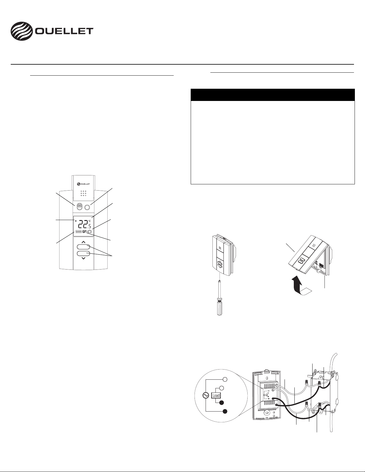
Description
The OTH770 thermostat has been designed for floor heating
systems. It has built-in ground fault protection and an input for
connecting a floor sensor, supplied with the thermostat.
Depending on the mode of application you choose, each thermostat
can be used to control the floor temperature (F mode) or to control
the ambient temperature while keeping the floor temperature within
comfortable and safe limits (AF mode).
Your thermostat has Vacation Mode which can be activated by
connecting an Aube telephone controller (CT240 or CT241) or any
other remote control device equipped with a normally open (NO) dry
contact.
On/Off switch
Appears when
the setpoint
temperature is
displayed
Heating intensity
Floor temperature
1
On
Floor LimitOff
2
limit button
Temperature display
Vacation mode indicator
(see section 4)
Ground fault indicator
3
4
1.
o
Installation
2.
CAUTION
• Installation must be carried out by a qualified electrician and
must comply with national and local electrical codes.
• Use this thermostat only for resistive load.
• Do NOT install the thermostat in an area where it can be
exposed to water or rain.
• To prevent severe shock or electrocution, always turn the
power OFF at the service panel before working with wiring.
• Install the thermostat onto an electrical box.
• This thermostat has tinned copper wires for line and load connections. Use special CO/ALR solderless connectors if you
connect the thermostat to aluminum wires.
n Turn off power to the heating system at the service panel in
order to avoid any risk of electrical shock.
o To remove the thermostat faceplate, loosen the screw at the bot-
tom of the thermostat and lift the bottom of the faceplate outwards towards you. (The screw remains captive on the base.)
Faceplate
Temperature adjustment
buttons
1
Switch the thermostat Off when it is not in use (e.g., during summer). To reset the ground fault protection, switch the thermostat to
Off and back to On.
2
The image disappears when heating is off.
3
The temperature limits are used only if your thermostat is configured in AF mode.
4
When the ground fault protection is activated, GFI appears on the
screen and the TEST button-light at the top of the thermostat illuminates (see section 7).
Base
p Connect the thermostat wires to the power supply and to the
load using solderless connectors for copper wires.
Power supply
240 V (120 V)
L2(N)
L1(L)
Red
L2(N)
L1(L)
Black
Red
Red
(White)
Red
(White)
Black
Black
Black
Load
OTH770 400-609-011-A 2009-07-29 1/3
Page 2

q Insert the temperature sensor wires through one of the openings
on the thermostat base and connect the wires to terminals 1 and
2 (no polarity).
• The sensor cable must not come in contact with the electrical
wires and must be routed outside the electrical box and follow
the wall down to the floor.
• Position the sensor cable such that it does not come in contact with the floor heating wires. The sensor must be centered
between two floor heating wires for best temperature control.
• Do NOT staple the sensor head (the plastic end) to the floor.
Doing so might damage the sensor. Any damage might not be
noticeable during testing but can become apparent several
days later.
r If you wish to connect a remote control device, insert the wires
(use 18- to 22-gauge flexible wires) through one of the two openings on the base and connect them to terminals 2 and 3 (no
polarity).
3.1 Temperature Display (S1)
Select between °C and °F.
3.2 Application Mode Selection (S2)
F: Select the F mode if you wish to control the floor temperature.
AF: Select the AF mode if you wish to control the ambient temperature.
q
The Vacation mode can be activated using a remote control device
equipped with a normally-open (NO) dry contact such as Aube’s
telephone controller (CT240/CT241).
In the Vacation mode, the temperature is reduced by 3.5°C (7°F) and
the thermostat buttons are locked to prevent any temperature
adjustment. The mode is indicated by the suitcase icon on the
screen. When the contact opens, the thermostat returns to normal
mode and to the initial temperature setpoint.
r
When the thermostat is powered, it first undergoes a
series of tests before displaying the actual temperature.
s
Vacation Mode
Power-up
Error Messages
The measured temperature is below the thermostat’s display range. Heating is activated.
4.
5.
6.
Floor sensor
To remote control device (see section 4)
s Push the excess length of the line voltage wires back inside the
electrical box. Install the thermostat base onto the electrical box
using the provided screws.
t Set the DIP switches (refer to section 3).
u Reinstall the thermostat faceplate on its base and secure it with
the screw. If there is a sticker on the screen, peel it off.
v Apply power to the heating system. Verify the installation by
making sure that the heating system can be turned on or off by
increasing or decreasing the setpoint respectively.
w Test the ground fault protection (refer to section 7).
NOTE: Keep the air vents (openings) at the top and bottom of the
thermostat clean and unobstructed at all times.
p
The configuration switches are located on the back of the faceplate.
Configuration
The measured temperature is above the thermostat’s display range. Heating is deactivated.
Verify the thermostat and sensor connections.
7.
t
The thermostat has built-in ground fault protection. In the event of a
ground fault, the ground fault protection mechanism on the thermostat trips and quickly stops the flow of electricity to prevent serious
injury.
Ground Fault Protection
7.1 Definition of a ground fault
Instead of following its normal safe path, electricity passes through a
person’s body to reach the ground. For example, a defective floor
3.
heating mat can cause a ground fault.
A ground fault protection thermostat does not protect against circuit
overloads, short circuits, or electrical shocks. For example, you can
still receive an electrical shock if you touch bare wires while standing
on a non-conducting surface such as a wood floor.
7.2 Resetting the Ground Fault Protection
The TEST button-light is On (red) when the
ground fault protection mechanism trips. If
the TEST button-light comes On during normal operation, reset the ground fault protection and check if the fault has been
caused by an external interference such as
a halogen button-light or an electric motor.
To reset the ground fault protection, switch
the thermostat to Off and back to On. The
TEST button-light will go off. However, if the
TEST button-light
OTH770 400-609-011-A 2009-07-29 2/3
Page 3

fault occurs again for unknown reasons, cut power to the floor heating system from the main electrical panel and have the installation
verified by an electrician.
7.3 Testing the Ground Fault Protection
To ensure the ground fault protection is always in working order, test
it once the thermostat is installed and test it every month thereafter.
n Increase the temperature sufficiently to start heating.
o Wait for about 5 seconds until the heat intensity indicator ( )
appears on the screen.
p Press the TEST button-light.
• If the TEST button-light does NOT illuminate, the test has
failed. Cut power to the heating system at the main electrical
panel, have an electrician verify the installation and, if necessary, replace the thermostat.
• If the TEST button-light illuminates, continue to step 4.
q Switch the thermostat to Off then back to On.
• If the TEST button-light goes off, the test has passed. Set
the thermostat back to the desired temperature and ignore the
remaining steps. The test is now completed.
• If the TEST button-light remains on, the test has failed. Continue to step 5.
r Switch the circuit breaker (at the service panel) of the heating
system to off then back to on.
s Repeat the test. If the test fails again, cut power to the heating
system at the main electrical panel, have an electrician verify the
installation and, if necessary, replace the thermostat.
u
The thermostat normally displays the actual temperature. To view the
setpoint temperature, press one of the buttons once. The setpoint will be displayed for 5 seconds. To change the setpoint, press
and release one of the buttons until the desired temperature is
displayed. To scroll the setpoint faster, press and hold the button.
Backlight
When you press on either of the buttons, the display is lit for 10
seconds. The setpoint appears for 5 seconds, then the actual temperature is displayed.
v
NOTE: The floor temperature limits are used only if your thermostat
is configured in AF mode.
The thermostat normally turns the floor heating system On or Off to
control the ambient temperature. However, if the floor temperature
drops below the minimum limit or rises above the maximum limit, the
thermostat will turn heating On or Off respectively to maintain the
floor temperature within the set limits, regardless of the ambient temperature.
The minimum and maximum floor temperature limits are factory-set
at 10 °C (50 °F) and 28 °C (82 °F) respectively. To modify the limits,
proceed as follows:
Temperature Setting
Floor Temperature Limits
n Press the Floor Limit button for 3 seconds. The ther-
mostat will display the minimum limit.
o Press the buttons to set the minimum limit.
p Press the Floor Temperature Limit button briefly. The
thermostat will display the maximum limit.
q Press the buttons to set the maximum limit.
r Press the Floor Limit button for 3 seconds to exit the
menu and save your modifications.
NOTE: The thermostat will also exit the menu and save your modifications if you do not press any button for 60 seconds.
:
w
Setpoint range - F mode: 5 °C to 40 °C (40 °F to 104 °F)
Display range - F mode: 0 °C to 60 °C (32 °F to 140 °F)
Resolution: ± 0.5 °C (1.0 °F)
Storage: -20 °C to 50 °C ( -4 °F to 120 °F)
8.
Heating cycle length: 15 minutes
Size (H • W • D): 124 x 70 x 23 mm (4.89 x 2.76 x 0.91 in)
Certification:
;
OUELLET CANADA INC. warrants the component parts of the
OTH770 against defects in material and workmanship for a three (3)
year period from the date of purchase, under normal use and service,
9.
when proof of purchase of such is provided to the manufacturer.
The obligation of Ouellet Canada Inc., under the terms of this
warranty, will be to supply a new unit and this releases the
manufacturer from paying the installation costs or other secondary
charges linked to replacing the unit or the component part(s).
If you have any questions on the product, call our technical support
team at:
Ouellet Canada Inc.
180, 3rd Avenue
L’ISLET, Quebec, Canada G0R 2C0
Quebec area: (418) 247-3947
Canada / U.S.: 1-800-463-7043
Fax: (418) 247-7801
Sales: info@ouellet.com
Web: www.ouellet.com
Technical Specifications
Model Supply
240 VAC,
60Hz
OTH770-GA
OTH770-GB
208 VAC,
60Hz
120 VAC,
60Hz
240 VAC,
60Hz
208 VAC,
60Hz
120 VAC,
60Hz
- AF mode: 5 °C to 30 °C (40 °F to 86 °F)
- AF mode: 0 °C to 50 °C (32 °F to 122 °F)
Warranty
THREE (3) YEAR LIMITED WARRANTY
Customer Service
Maximum Load
Current Power
3600 W
3120 W
1800 W
15 A
3600 W
3120 W
1800 W
Wiring
4 wires
double pole
Leakage
10.
current
5 mA
15 mA
11.
12.
OTH770 400-609-011-A 2009-07-29 3/3
 Loading...