

Ouellet MPD18KCH22S-O, MPD24KCH21S-O, MPD42KCH21S-O, MPD36KCH21S-O, MPD30KCH21S-O Owner's Manual
Page 1
Owner’s Manual
DUCTLESS MULTIZONE
HEAT PUMP
22-21 SEER INVERTER
18 000 to 42 000 BTU/hr
Models:
MPD18KCH22S-O
MPD24KCH21S-O
MPD30KCH21S-O
MPD36KCH21S-O
MPD42KCH21S-O
before operating the unit and keep it for future reference.
Please read this owner’s manual carefully
INS527-201801-01
Page 2

TABLE OF CONTENTS
Operation notices .................................................................................................................................................................3
Explanation of symbols
Precautions
Working temperature range
Parts name
................................................................................................................................................................................4
.................................................................................................................................................................................6
Maintenance .............................................................................................................................................................................7
Cleaning and maintenance
Preparation before installation ..................................................................................................................................8
Required installation clearance distances diagram
Tools required for installation
Selection of installation location
Requirements for electrical connection
Installation .............................................................................................................................................................................. 11
Installation of outdoor unit
Vacuum pumping ...............................................................................................................................................................16
........................................................................................................................................................3
...............................................................................................................................................6
.................................................................................................................................................7
....................................................................................................8
.............................................................................................................................................9
.......................................................................................................................................9
...................................................................................................................... 10
.............................................................................................................................................. 11
Checking after installation.......................................................................................................................................... 17
Other consideration ......................................................................................................................................................... 18
IPipe expanding method
.................................................................................................................................................. 18
This appliance is not intended for use by people (including children) with
reduced physical, sensory or mental capabilities, or lack of experience and
knowledge, unless they are under the supervision or instruction
concerning use of the appliance by a person responsible for their safety.
Children should be supervised to ensure that they do not play with the appliance.
2
Page 3

OPERATION NOTICES
EXPLANATION OF SYMBOLS
Indicates a hazardous situation that, if not avoided,
DANGER
will result in serious injury or death.
WARNING
CAUTION
NOTICE
Indicates a hazardous situation that, if not avoided,
could result in serious injury or death.
Indicates a hazardous situation that, if not avoided,
may result in minor or moderate injury.
Indicates important but not hazard-related information,
used to indicate risk of property damage.
Indicates a hazard and it is assigned to the signal words
DANGER, WARNING or CAUTION.
3
Page 4

PRECAUTIONS
Only use the air conditioner as instructed in this booklet. These instructions are not intended to cover
every possible condition and situation. As with any electrical household appliance, common sense and
caution are therefore always recommended for installation, operation and maintenance.
WARNING
Operation and Maintenance
• This appliance can be used by people (including children of 8 years old and above) with reduced
physical, sensory or mental capabilities, or lack of experience and knowledge, as long as they are
under the supervision or instruction concerning use of the appliance by a person responsible for
their safety.
• Children shall not play with the appliance.
• Cleaning and user maintenance shall not be made by children.
• Disconnect power supply when cleaning. Otherwise, it may cause electric shock.
• If the power supply wire is damaged, it must be replaced by a qualified person in order to avoid
a hazard.
• Do not wash with water to avoid electric shock.
• Maintenance must be performed by qualified person. Otherwise, it may cause personal injury or damage.
• Do not repair the appliance by yourself. It may cause electric shock or damage. Please contact
a qualified person when you need to repair it.
• Do not extend fingers or objects into air inlet or air outlet. It may cause personal injury or damage.
• Do not block air outlet or air inlet. It may cause malfunction.
• When below phenomenon occurs, please turn off the appliance and disconnect power immediately,
and then contact a qualified person for service:
- There’s abnormal sound during operation.
- Circuit break trips off frequently.
- The appliance gives off burning smell.
• If the appliance operates in an inappropriate environment or under abnormal conditions, it may cause
malfunction, electric shock or fire hazard.
• Do not step on top panel of outdoor unit, or put on heavy objects. It may cause damage or personal
injury.
4
Page 5

PRECAUTIONS
WARNING
Wiring
• Installation must be performed by a qualified person. Otherwise, it may cause personal injury or
damage.
• Must follow the electric safety regulations when installing the unit.
• According to the local safety regulations, use qualified power supply circuit and circuit breaker.
• Install a circuit breaker of adequate capacity only used for the system; otherwise, it may cause
malfunction.
• An all-pole disconnection switch having a contact separation of at least 1/8" (3 mm) in all poles should
be connected in fixed wiring.
• The appliance should be properly grounded. Incorrect grounding may cause electric shock.
• Make sure the power supply matches with the requirement of the appliance. Unstable power supply
or incorrect wiring may cause malfunction of the unit, electric shock or fire hazard.
• Properly connect the live wire, neutral wire and grounding wire.
• Be sure to cut off the power supply before proceeding any work related to electricity and safety.
• Do not turn the power on before finishing installation.
• If the power supply or signal control wires are damaged, it must be replaced by a qualified person
in order to avoid problems.
• The temperature of refrigerant circuit will be high, please keep the interconnection cable away from
the copper tube.
• The appliance shall be installed in accordance with national wiring regulations.
• Installation must be performed in accordance with the requirement of NEC and CEC by a qualified
person only.
• The heat pump is a first class electric appliance. It must be properly grounded with specialized
grounding device by a qualified person. Please make sure it is always properly grounded, otherwise
it may cause electric shock.
• The yellow-green wire in the appliance is the grounding wire, which can’t be used for other purposes.
• The grounding resistance should comply with national electric safety regulations.
• All wires of indoor unit and outdoor unit should be connected by a qualified person.
• If the length of power connection wire is insufficient, please contact the dealer for a new one.
Do not extend the wire yourself.
5
Page 6
PRECAUTIONS
WARNING
Location
• If you need to relocate the appliance to another place, only a qualified person can perform the work.
Otherwise, it may cause personal injury or damage.
• Select a location which is out of reach for children and far away from animals or plants. If it is unavoidable, please add a fence around the outdoor unit for safety purpose.
• Instructions for installation and use of this product are provided by the manufacturer.
WORKING TEMPERATURE RANGE
Outdoor side DB/WB °C (°F)
Max. cooling 48/- (118/-)
Max. heating 27/- (80/-)
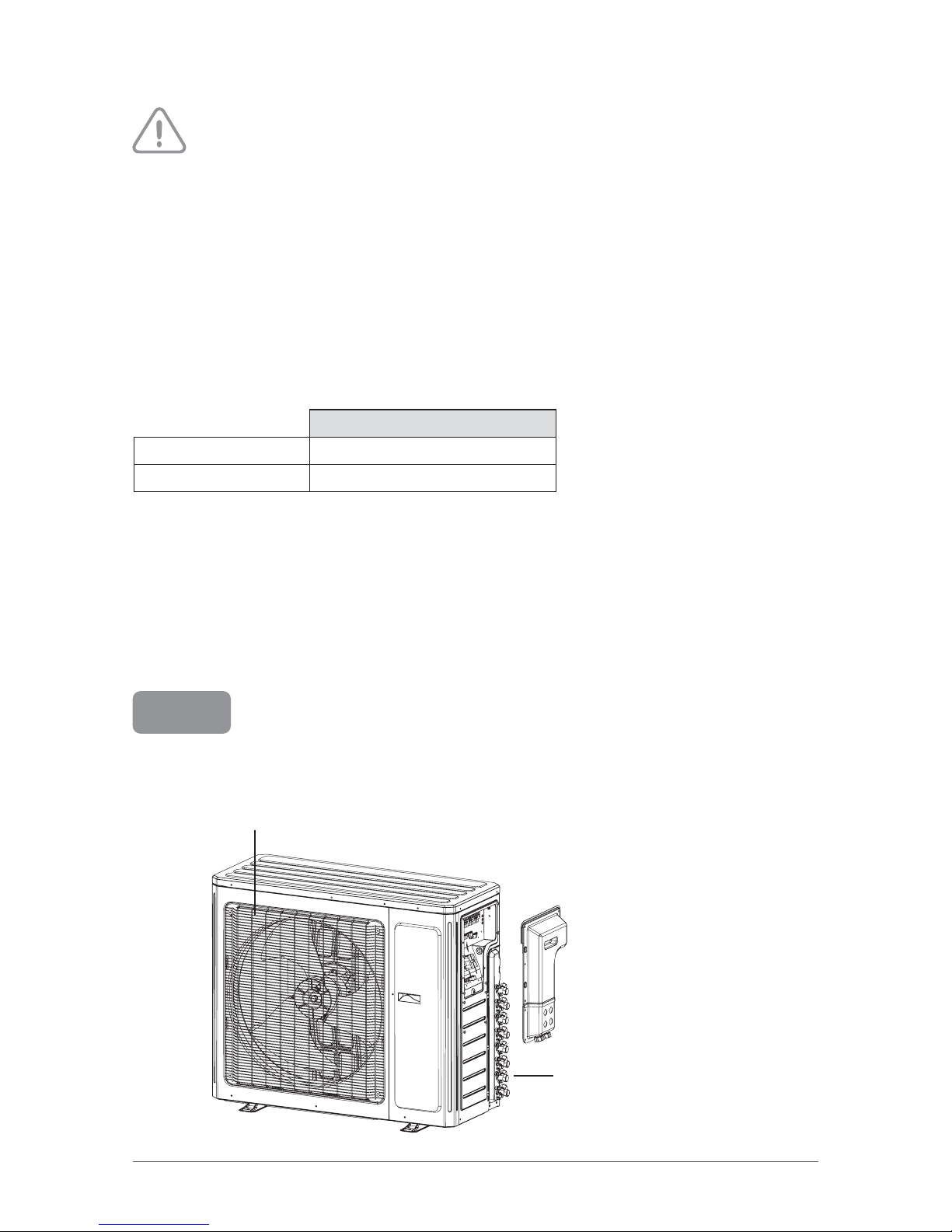
PARTS NAME
NOTICE
Outdoor unit
Air outlet
Actual product may be different from below graphics, please refer to actual product for
reference purposes.
Valve
6
Page 7

MAINTENANCE
CLEANING AND MAINTENANCE
WARNING
• Turn off the unit and disconnect the power before cleaning to avoid electric shock.
• Do not wash the unit with water to avoid electric shock.
• Do not use volatile liquid or mineral oils to clean the unit.
• Use suitable instruments for the refrigerant R410A.
• Do not use any other refrigerant than R410A.
Cleaning the surface of outdoor unit
When the surface of outdoor unit is dirty, use a softdry cloth or lightly moistened with water to wipe it.
Checking before usage
1. Check that air inlets and air outlets are not blocked.
2. Check if circuit breaker and connection are in good condition.
3. Check that drainage pipe is not damaged or blocked.
Checking after usage
1. Disconnect power supply.
2. Check whether mounting bracket for outdoor unit is damaged or corroded.
If so, please contact the dealer.
Notice for recovery
1. Many packing materials are recyclable. Please dispose of them in appropriate recycling bin.
2. If you want to get rid of the device, please contact a local recycling center for the correct
disposal method.
7
Page 8

PREPARATION BEFORE INSTALLATION
REQUIRED INSTALLATION CLEARANCE DISTANCES DIAGRAM
NOTICE
Actual product may be different from below graphics, please refer to actual product for
reference purposes.
Models MPD18, MPD24, MPD30
B
11 13/16" (300 mm)
or more
Space to the wall
C
78 3/4" (2000 mm)
or more
(Air outlet side)
A 19 11/16" (500 mm) or more
Space to the obstruction
A
B
C
D
11 13/16" (300 mm)
or more
(Air inlet side)
Models MPD36, MPD42
B
19 11/16" (500 mm)
or more
Space to the wall
C
78 3/4" (2000 mm)
or more
(Air outlet side)
8
E
19 11/16" (500 mm)
or more
Space to the obstruction
A 39 3/8" (1000 mm) or more
A
Space to the obstruction
B
C
D
19 11/16" (500 mm)
or more
(Air inlet side)
E
19 11/16" (500 mm)
or more
Space to the obstruction
Page 9

TOOLS REQUIRED FOR INSTALLATION
• Level meter
• Screwdrivers
• Impact drill
• Drill head
• Pipe expander
• Torque wrench
• Open-end wrench
• Pipe cutter
• Leakage detector
• Vacuum pump
• Manometer
• Multimeter
• Inner hexagon spanner
• Measuring tape
NOTICE
Contact a qualified person for installation.
SELECTION OF INSTALLATION LOCATION
Basic requirements
Installing the unit in the following places may cause malfunction. If it is unavoidable, please consult
a qualified person:
• A place with strong heat sources, vapors, flammable or explosive gas or volatile objects spread
in the air.
• A place with high-frequency devices (such as welding machine, medical equipment).
• A place near coastal regions.
• A place with oil or fumes in the air.
• A place with sulphurous gas.
• Other places with special environment.
• Near a swimming pool.
Outdoor unit
• Select a location where the noise and outflow air emitted by the outdoor unit will not affect
neighborhood.
• The location should be well ventilated and dry, where the outdoor unit won’t be exposed directly
to sunlight or strong wind.
• The location should be able to withstand the weight of outdoor unit.
• Make sure that the installation follows the requirement of clearance distance diagram.
• Select a location which is out of reach for children and far away from animals or plants. If it is
unavoidable, please add a fence for safety purpose.
9
Page 10

REQUIREMENTS FOR ELECTRICAL CONNECTION
Safety precautions
• You must follow the electric safety regulations when installing the unit.
• According to the local safety regulations, use qualified power supply circuit and circuit break.
• Make sure the power supply matches with the requirement of the device. Unstable power supply
or incorrect wiring may cause malfunction and damage the unit or fire hazard.
• Properly connect the live wire, neutral wire and grounding wire.
• The connection pipes and wires from units A and B must correspond.
• Incorrect wire connections may cause some electric components to malfunction. After attaching
the cable, ensure that the leads between connection to a fixed point are spaced out.
• Cut off the power supply before proceeding any work related to electricity.
• Do not turn on the power before finishing installation.
• The temperature of refrigerant circuit will be high, please keep the interconnection cable away
from the copper tube.
• The appliance shall be installed in accordance with national wiring regulations.
Grounding requirements
• The heat pump is a first class electric appliance. It must be properly grounded by a qualified person
with specialized grounding device. Please make sure it is always grounded effectively, otherwise it
may cause electric shock.
• The yellow-green wire in the appliance is the grounding wire, which cannot be used for other
purposes.
• The grounding resistance should comply with national electric safety regulations.
• An all-pole disconnect switch having a contact separation of at least 1/8" (3 mm) in all poles should
be connected in fixed wiring.
10
Page 11

INSTALLATION
CAUTION
Installation must be performed in accordance with the NEC/CEC by authorized personnel only.
INSTALLATION OF OUTDOOR UNIT
Step 1: Fix the support of outdoor unit (select it according to the actual installation situation)
• Use bolts to secure the unit to a flat, solid floor. When mounting the unit on a wall or the roof, make
sure the support is firmly secured so that it cannot move in the event of intense vibrations or a strong
wind.
• Do not install the outdoor unit in pits or air vents.
Notes:
• Take sufficient protective measures when installing the outdoor unit.
• Make sure the support can withstand at least four times the unit weight.
• The outdoor unit should be installed at least 3/16" (30 mm) above the
floor in order to install drain joint.
Step 2: Install drain joint
• Connect the outdoor drain joint into the hole
on the chassis, as shown in the picture below.
• Connect the drain hose into the drain vent.
Step 3: Fix outdoor unit
• Place the outdoor unit on the support.
drain vent
drain hose
at least 1 3/16" (30 mm)
above the floor
chassis
outdoor drain joint
foot holes
• Fix the foot holes of outdoor unit with bolts.
foot holes
11
Page 12

Step 4: Connect indoor and outdoor pipes
• Remove the screw on the right handle of outdoor
unit and then remove the handle.
• Remove the valve cap and align the pipe joint on the flared
orifice of the pipe.
• Pre-tighten the union nut by hand.
liquid
valve
pipe joint
Hex nut diameter
screw
handle
liquid pipe
gas pipe
gas valve
union nut
Tightening torque
(N-m)
Φ 6 15~20
• Tighten the union nut with torque wrench by referring
to the sheet below.
Φ 9.52 30~40
Φ 12 45~55
Φ 16 60~65
Φ 19 70~75
NOTES:
• If the pipe diameter of the outdoor unit doesn’t match the piping connection size of the indoor unit,
use the piping connection size of the indoor unit and add the adaptor supplied with the indoor unit.
• Make sure to label each pipe so you know which system it belongs to, in order to avoid inaccurate
piping.
Adaptor
12
Page 13

Step 5: Wiring of the unit
• Remove the wire clip; connect the power connection wire and signal control wire to the wiring
terminal according to the color; fix them with screws.
MPD18 MPD24
To unit A
L1
L2
L1
L2
Power cord
connecting
cable
To unit B
connecting
cable
L1 L2
To the power supply
L1 L2
L2
L1
L1 L2
L1 L2
L1 L2
MPD30 MPD36
MPD42
To unit A
L1 L2
To unit B
To unit C
To unit D
L1 L2
Power cord
L2
L1
To unit A
connecting
cable
To unit B
connecting
cable
To unit C
C
connecting
cable
To the power supply
C
C
C
L2
L1
L2
L1
C
C
To unit A
To unit B
To unit C
To unit D
To unit E
Connecting
cable
L2
L1
L2
L1
Connecting
cable
L1 L2
L1 L2
Power cord
Notes:
• These wiring diagrams are for reference only, please always refer to the one on the actual unit.
• Actual product may be different from above graphics, please refer to actual product for reference
purposes.
Connecting
cable
To the power supply
C D
C D
CC
Connecting
cable
L1 L2
L1 L2
Power cord
Connecting
cable
L2
L1
L2
L1
Connecting
cable
C
Connecting
cable
C
C
C
Connecting
cable
To the power supply
D
D
To the power supply
To the power supply
CD
C
CD
C
cable
Connecting
cable
E
E
C
C
13
Page 14

Step 6: Pipe arrangement
• Use suitable connecting pipes and equipment for the
refrigerant R410A.
• The pipes should be placed along the wall,
slightly bent and if possible be hidden.
The minimum bending semi diameter is 4" (100 mm).
• If the outdoor unit is higher than the wall hole,
you must set a U-shaped curve in the pipe before
pipe goes into the house, in order to prevent rain
from getting in.
Maximum length of connection pipe and maximum height difference
wall
U-shaped curve
drain hose
Outdoor unit
Equivalent length of the farthest fitting pipe L
L4L3L2 L5L1
Indoor unit
a
b
indoor units H2
Height difference between
Indoor unit
c
d
e
Height difference between indoor unit and outdoor unit H1
Model #
Max. total length
of connection pipe
L1+L2+L3+L4+L5
Max. length
for single unit
Lx
Max. height
difference
outdoor to
indoor unit
H1
Max. height
difference between
indoor units
H2
ft. (m) ft. (m) ft. (m) ft. (m)
MPD18KCH22SO 66 20 33 10 33 10 33 10
MPD24KCH21SO 197 60 66 20 33 10 33 10
MPD30KCH21SO 230 70 82.5 25 49.5 15 25 7.5
MPD36KCH21SO 246 75 82.5 25 49.5 15 25 7.5
MPD42KCH21SO 246 75 82.5 25 49.5 15 25 7.5
x
14
Page 15

The outdoor unit is shipped with a full charge of R-410A refrigerant for the following total piping
lengths:
Model #
Pre-charge length
ft. (m)
MPD18KCH22SO 33 10
MPD24KCH21SO 98 30
MPD30KCH21SO 130 40
MPD36KCH21SO 130 40
MPD42KCH21SO 130 40
• For pipe runs over this limit, add 0.2 oz/ft (20 g/m) of additional refrigerant.
15
Page 16

VACUUM PUMPING
Humid air left inside the refrigerant circuit can cause compressor malfunction. After having connected the
indoor and outdoor units, bleed the air and humidity from the refrigerant circuit using a vacuum pump.
1. Unscrew and remove the caps from the 2-way
and 3- way valves.
2. Unscrew and remove the cap from the service
valve.
3. Connect the vacuum pump hose to the
service valve.
4. Operate the vacuum pump for 10-15 minutes
until an absolute vacuum of 3/8" (10 mm) Hg
has been reached.
5. With the vacuum pump still in operation,
close the low-pressure knob on the vacuum
pump coupling. Stop the vacuum pump.
6. Open the 2-way valve by 1/4 turn and then
close it after 10 seconds. Check all the joints
for leaks using liquid soap or an electronic
leak device.
Vacuum pump Vacuum pump
7. Turn the body of the 2-way and 3-way valves.
Discon-nect the vacuum pump hose.
8. Replace and tighten all the caps on the valves.
Service
inlet
(2) Turn
(8) Secure
INDOOR
UNIT
Refrigerant fluid
direction offlow
3-way valve
(7) Turn to
open fully
Valve cap
(8) Secure
(2) Turn
Vacuum pump
2-way valve
(6) Open by 1/4 turn
(7) Turn to open fully
Valve cap
(2) Turn
(8) Secure
Connect to the
indoor unit
16
Page 17

CHECKING AFTER INSTALLATION
Check the following items after finishing installation:
Items to check Possible malfunction
Has the unit been installed solidly? The unit may drop, shake or emit noise.
Have you done the refrigerant leakage test? It may cause insufficient cooling (heating) capacity.
Is heat insulation of pipeline sufficient? It may cause condensation and water dripping.
Is water drained well? It may cause condensation and water dripping.
Is the voltage of power supply according to the
voltage marked on the nameplate?
Are electric wiring and pipes installed correctly? It may cause malfunction or damaging the parts.
Is the unit grounded securely? It may cause electric leakage.
Does the power wire follow the specifications? It may cause malfunction or damaging the parts.
Is there any obstruction in the air inlet and
outlet?
Are dust and installation debris removed? It may cause malfunction or damaging the parts.
Are gas valve and liquid valve of connection
pipe completely opened?
Have the length of refrigerating pipe and refrigerant charge amount been recorded?
It may cause malfunction or damaging the parts.
It may cause insufficient cooling (heating) capacity.
It may cause insufficient cooling (heating) capacity.
It is not easy to figure out the charge amount of
refrigerant if it has not been recorded.
17
Page 18

OTHER CONSIDERATIONS
PIPE EXPANDING METHOD
Note:
Improper pipe expanding is the main cause of refrigerant leakage.
Please expand the pipe according to the following steps:
1. Cut the pipe
• Confirm the pipe length according to the
distance between indoor and outdoor unit.
• Cut the pipe with pipe cutter.
pipe
pipe cutter
leaning uneven burr
2. Remove the burrs
• Remove the burrs with a sharper and
prevent the burrs from getting into the pipe.
pipe
shaper
downwards
5. Expand the port
• Expand the port with an expander.
expander
hard
mold
pipe
Note:
"A" varies according to the diameter, please refer to
the chart below:
Outer diameter
(mm)
A (mm)
Max Min
Φ 6 - 6.35 (1/4’’) 1.3 0.7
Φ 9.52 (3/8’’) 1.6 1.0
Φ 12 - 12.7 (1/2’’) 1.8 1.0
Φ 15.8 - 16 (5/8’’) 2.4 2.2
3. Put on suitable insulating pipe
4. Put on the union nut
• Remove the union nut on the indoor connection
pipe and outdoor valve; install the union nut on
the pipe.
union pipe
pipe
18
6. Inspection
• Check the quality of the expansion. If the surface
is not smooth, repeat the previous steps.
smooth surface
improper expanding
the length is equal
leaning crackdamaged
surface
uneven
thickness
 Loading...