

Page 1
67221 12/13 (JRK)
© 2013 OJ Electronics A/S
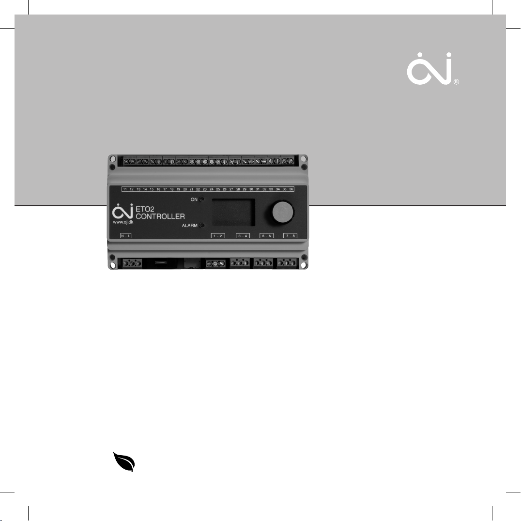
Type ETO2
Controller for ice and snow melting
English
Français
GREEN COMFORT
Maximum comfort with low energy consumption
Page 2
© 2013 OJ Electronics A/S
English
Instruction
ETO2 is an electronic controller for fully automatic, economical
ice and snow melting on outdoor surfaces and in gutters.
Ice forms due to a combination of low temperature and
moisture. ETO2 detects both temperature and moisture, and the
ice and snow melting system will usually only be activated if ice
or snow is present. ETO2 is suitable for controlling both electric
heating cables and hydronic heating pipes.
Product programme
ETO2-4550 Thermostat.
ETOG-55 Ground sensor for detecting temperature
and moisture.
ETOG-56/ETOK-1 Embedded ground sensor for detecting
temperature and moisture.
ETOR-55 Gutter sensor for detecting moisture.
ETF-744/99 Outdoor sensor for detecting temperature.
ETF-522 Water pipe sensor for detecting
temperature.
WARNING! – Read this manual!
Carefully read this instruction manual in its entirety,
paying close attention to all the warnings listed below. Make
sure that you fully understand the use, displays and limitations
of the controller because any confusion resulting from
neglecting to follow this instruction manual, or from improper
use of the device it concerns, may cause an installer to commit
errors which could lead to ice and snow conditions capable of
causing serious injury or death.
WARNING! – Note that snow, ice and icicles may be
present even though you follow the instructions
contained in this manual.
You are strongly advised to monitor any unexpected build-up of
snow, ice or icicles. As an additional safety measure, you should
always perform a manual inspection of public areas in order to
ensure safe access to the controlled areas.
WARNING! – Important safety instructions.
Disconnect the power supply before carrying out
any installation or maintenance work on this control unit and
associated components. This control unit and associated
components should only be installed by a competent person
(i.e. a qualified electrician). Electrical installation must be in
accordance with appropriate statutory regulations.
NOTE! – The output relays are potential free. The
installer must connect a power source, e.g. from an
electrical panel.
CE MARKING FOR EU
OJ Electronics A/S hereby declares that the product is
manufactured in accordance with Council Directive 2004/108/
EC on electromagnetic compatibility (and subsequent
amendments) and Council Directive 2006/95/EEC on electrical
equipment designed for use within certain voltage limits.
Applied standards
ETO2-4550-EU28: CE marking LVD/EMC: EN60730-2-9
ETO2-4550-US28: CAN/CSA E 60730-2-9:01.
ETO2-4550-RU28: CE marking LVD/EMC: EN60730-2-9
The product may only be used if the complete installation
complies with current directives.
The product carries a manufacturer’s warranty if installed in
accordance with these instructions and current regulations.
If the product has been damaged in any way, e.g. during
transport, it must be inspected and checked by authorised
personnel before being connected to the power supply.
TECHNICAL DATA
Thermostat ETO2-4550:
Designed for indoor mounting only!
Supply voltage ............................115/240 V AC ±10%, 50-60 Hz
Supply voltage for ETOG/ETOR heating (SMPS) ..28 V DC, 8 VA
3 output relays (potential-free contact, NO) ...................3 X 16 A
Alarm relay (potential-free contact, NO) ........................ max. 5 A
Control signal to actuator (mixing valve) .....................0-10 V DC
3
Page 3

© 2013 OJ Electronics A/S
INSTRUCTION
Type ETO2
English / Instruction
Supply voltage to actuator
(mixing valve) .................................max. 48 V AC/DC / max. 2 A
On/o dierential ........................................................1.8°F / 1°C
Temperature range ....................................-4/+50°F / -20/+10°C
Ambient temperature .................................... 32/122°F / 0/+50°C
Ambient air humidity .......................................................10-95%
Enclosure rating .....................................................
Weight .............................................................
Nema 1- IP 20
17.46 oz - 600 g
Dimensions H/W/D ...........3.54/6.14/1.77 Inches - 90/156/45 mm
Type ................................................................................. 1B
Control pollution degree ............................................................2
Rated impulse voltage .......................................................... 4 kV
Ground sensor - type ETOG-55:
Designed to be embedded in outdoor surfaces.
Detection ............................................ Moisture and temperature
Mounting ..........................................................Outdoor surfaces
Enclosure rating .................................................
NEMA 6P - IP 68
Ambient temperature ............................. -57/+158°F / -50/+70°C
Dimensions
H/Ø................................1.26/2.36 Inches - 32/60 mm
Ground sensor - ETOG-56/ETOK-1:
Designed to be embedded in outdoor surfaces.
Detection ........................................... Moisture and temperature
Mounting .........................................................Outdoor surfaces
Enclosure rating .................................................
NEMA 6P - IP 68
Ambient temperature ............................. -57/+158°F /-50/+70°C
Dimensions, sensor H/Ø .................
1.26/2.36 Inches - 32/60 mm
Dimensions, tube H/Ø ...................3.07/2.50 Inches - 78/63,5 mm
Gutter sensor - type ETOR-55:
Designed to be mounted in gutter or downpipe. Is used together
with outdoor sensor type ETF-744/99.
Detection ........................................................................Moisture
Mounting ...................................................... Gutter or downpipe
Enclosure rating .................................................
NEMA 6P - IP 68
Ambient temperature ............................. -57/+158°F / -50/+70°C
Dimensions H/W/D ...........
4.13/1.18/0.51 Inches - 105/30/13 mm
Outdoor sensor - ETF-744/99:
Detection ................................................................. Temperature
Mounting ...............................................................................Wall
Enclosure rating ...................................................
NEMA 3 - IP 54
Ambient temperature ............................. -57/+158°F / -50/+70°C
Dimensions H/W/D .............
3.39/1.77/1.38 Inches - 86/45/35 mm
Water pipe sensor - ETF-522:
Detection ................................................................. Temperature
4
Mounting ...........................................................Strapped to pipe
Enclosure rating ...................................................
NEMA 3 - IP 54
Ambient temperature ........................... -40/+248°F / -40/+120°C
Dimensions
Ø/L ...............................0,26/1.97 Inches - 6,5/50 mm
NOTE: The snow and ice melting system is deactivated
in the event of sensor failure - regardless of sensor type.
SENSOR INSTALLATION
Ground sensor - ETOG, figs 1+3:
For installation in outdoor surfaces where ice and snow are a
regular problem. The sensor must be embedded horizontally
with its top flush with the surrounding surface.
The sensor cable must be installed in accordance with current
regulations.
NOTE: We strongly recommend the use of cable pipes in order
to protect the sensor cable. Detailed installation instructions are
supplied with the sensor.
With ETOG-55, use the accompanying installation plate.
With ETOG-56, use the ETOK-1 mounting kit.
NOTE: Remove the installation plate from ETOG-55
before initial start-up.
Gutter sensor - ETOR, figs 2+4:
For installation in a gutter or downpipe on the sunny side of
the building. It is important to ensure that the sensor contact
elements face against the flow of melt water. If necessary,
two sensors can be installed in parallel. Detailed installation
instructions are supplied with the sensor.
Note that the pink and grey wires are not used.
Outdoor sensor - ETF-744/99, figs 2+4:
Although ETF is designed for use with gutter sensor ETOR, it
can also be used separately for the detection of temperature
alone. The sensor should be mounted on the wall beneath the
eaves on the north side of the building.
Water pipe sensor - ETF-522:
Is only used with hydronic heating systems to detect the
temperature of the supply and return water. Must be fastened to
the pipe directly with strips.
Sensor cables:
With the exception of ETOG-56, which has a
cable, ETOG and ETOR sensors are supplied with a
32.8 ft (10 m)
82.02 ft
Page 4

© 2013 OJ Electronics A/S
Type ETO2
(25 m) cable, which can be extended up to approx. 656 ft - (200
m) using standard installation cable:
ETOG and
4x16 AWG (4x1.5 mm² ) for ETOR. The ETF cable can
be extended up to approx.
6x16 AWG (6x1.5 mm² ) for
164 ft (50 m) in length. Sensor cables
must be installed in accordance with current regulations. They
must never be installed parallel to power cables as electrical
interference may distort the sensor signal.
ETO2:
The unit is intended to be DIN-rail mounted in an approved
panel.
Wall mounting:
For USA and Canada: The thermostat can be wall-mounted in a
specially designed and UL-approved metal box (accessory).
The accompanying plastic cover can be used for wall mounting
in an indoor area.
Connect supply voltage to terminals N and L. All electrical and
mechanical installation must be performed in accordance with
applicable local regulations.
SETUP, ELECTRIC HEATING
• 1-zone electric heating control with ETOG (figs 3+6):
Connect 1 or 2 ETOG sensors to terminals 11-20.
Connect heating cable to potential-free output relays 1, 2 and
3 according to fig. 8.
• 1-zone electric heating control with ETOR + ETF
(figs 4+7):
Connect 1 or 2 ETOR sensors to terminals 11-20.
Note that the pink and grey wires are not used.
Connect 1 ETF sensor to terminals 31-32.
Connect heating cable to potential-free output relays 1, 2 and
3 according to fig. 8.
• 2-zone electric heating control with ETOG (figs 3+6):
Connect 2 ETOG sensors to terminals 11-20.
Connect heating cable for zone 1 to potential-free output
relay 1 according to fig. 8.
Connect heating cable for zone 2 to potential-free output
relay 2 according to fig. 8.
• 2-zone electric heating control with ETOR (figs 4+7):
Connect 2 ETOR sensors to terminals 11-20.
Note that the pink and grey wires are not used.
Connect heating cable for zone 1 to potential-free output
English / Instruction
relay 1 according to fig. 8.
Connect heating cable for zone 2 to potential-free output
relay 2 according to fig. 8.
• 2-zone electric heating control with ETOG and ETOR
(figs 5+6+7):
Connect 1 ETOG sensor to terminals 11-16 as sensor 1.
Connect 1 ETOR sensor to terminals 17-20 as sensor 2.
Note that the pink and grey wires are not used.
Connect heating cable for zone 1 (ground) to potential-free
output relay 1 according to fig. 8.
Connect heating cable for zone 2 (roof) to potential-free
output relay 2 according to fig. 8.
• 1-zone electric heating control with output control
(Y/∆) (figs 6+9+10):
Advanced 2-stage control with ETOG. 1/3 power on heating
cables in afterrun.
Connect 1 or 2 ETOG sensors to terminals 11-20.
Connect external contactor/relays to potential-free output
relays 1, 2 and 3 according to fig. 10.
SETUP, HYDRONIC HEATING
• 1-zone hydronic heating control for controling the supply
water temp. with mixing valve (figs 6+11+13+16):
Connect 1 or 2 ETOG sensors to terminals 11-20 (fig. 6).
Connect supply voltage (24 V AC) for mixing valve to
terminals 25-26 (fig. 13).
Connect mixing valve to terminals 21-24 (fig. 13).
Connect ETF-522 supply and return sensors to terminals
27-30 (fig. 16).
Connect primary pump to potential-free output relay 1
according to fig. 14.
Connect secondary pump to potential-free output relay 2
according to fig. 14.
• 1- or 2-zone hydronic heating control, simple
(figs 3+6+12):
Connect 1 or 2 ETOG sensors to terminals 11-20 (fig. 6).
Connect circulation pump for zone 1 to potential-free output
relay 1 according to fig. 14.
If zone 2 is used, connect circulation pump for zone 2 to
potential-free output relay 2 according to fig. 14.
Same application setup as for 1- or 2-zone electric heating
control, see User Manual, Startup.
5
Page 5
© 2013 OJ Electronics A/S
INSTRUCTION
Type ETO2
English / Instruction
REMOTE CONTROL (fig. 15):
The forced heat and standby functions can be remotely con-
trolled by wiring ETO2 to external buttons/relays (normally open).
Connect external standby button to terminals 33-34.
Connect external forced heat button to terminals 35-36.
TESTING SNOW MELTING SYSTEM
After completing installation and application setup, it is
recommended that the snow melting system is tested.
1. Adjust SET TEMP in the setup menu to max. temperature.
2. Pour some water onto the sensor (ETOG/ETOR).
3. The output relay for the heating cable in the zone concerned
should activate and ON should be indicated on the ETO2
display. Check that the heating cable becomes warm, check
the voltage if possible.
4. After testing, adjust SET TEMP back to the desired setting
(factory setting = +3.0°C / 37.4°F).
WIRING (fig. 16):
TERMINAL COLOUR CODE WIRING
N, L Supply voltage, 115-240 V AC
1, 2 Alarm relay (potential-free), max. 5 A
3, 4 Output relay 1, 16 A (potential-free),
Heating cable 1 (zone 1) /
5, 6 Output relay 2, 16 A (potential-free),
Heating cable 2 (zone 2) /
7, 8 Output relay 3, 16 A (potential-free),
11, 12 brown/green Sensor heating 1+2, ETOG 1+2 and
13, 14 grey/pink Temperature sensor, ETOG 1
15, 16 yellow/white Moisture sensor 1, ETOG 1/ETOR 1
17, 18 grey/pink Temperature sensor, ETOG 2
19, 20 yellow/white Moisture sensor 2, ETOG 2 /ETOR 2
21, 22 3- or 4-way mixing valve, 0-10 V
23, 24 3- or 4-way mixing valve, 24 V AC
25, 26 24 V AC from external supply for 3-
27, 28 Supply water temperature sensor,
50/60Hz
Primarypump
Secondary pump
Heating cable 3
ETOR 1+2
or 4-way mixing valve
ETF-522
29, 30 Return water temperature sensor,
ETF-522
31, 32 Outdoor temperature sensor, ETF
33, 34 Standby, external input
35, 36 Forced control heat, external input
ETOR SENSOR WIRES :
Note that the pink and grey wires are not used.
Environment protection and recycling
Help protect the environment by disposing of the packaging and
redundant products in a responsible manner.
Product disposal
Products marked with this symbol must not be
disposed of along with household refuse, but must be
delivered to a waste collection centre in accordance
with current local regulations.
Figures
Fig. 1 Installation of ETOG ground sensor
1 Sensor
2 Installation plate
3 Heating element
Fig. 2 Installation of ETOR gutter sensor and ETF outdoor
sensor
1 Thermostat ETO2
2 Gutter sensor
3 Outdoor sensor
Fig. 3 1-zone electric heating with ETOG sensor
Fig. 4 1-zone electric heating with ETOR/ETF sensor
Fig. 5 2-zone electric heating (roof/ground)
Fig. 6 ETOG connection
Fig. 7 ETOR connection
Fig. 8 Heating cable connection, example
Fig. 9 2-stage electric heating control (Y/∆)
Fig. 10 Advanced 2-stage connection (Y/∆)
Fig. 11 1-zone hydronic heating control for control of supply
water temp. with mixing valve
Fig. 12 1- or 2-zone hydronic heating control, simple (same
application setup as 1- or 2-zone electric heating
control)
Fig. 13 Hydronic mixing valve connection
Fig. 14 Hydronic pump connection
Fig. 15 Connections for remote control of standby and forced
heat
Fig. 16 ETO2 controller, terminal overview
6
Page 6

© 2013 OJ Electronics A/S
English
User Manual
CONTENTS
Glossary .............................................................. Page 41
Introduction ............................................................. Page 41
Startup ............................................................... Page 42
Operation .............................................................. Page 43
Main menu ............................................................. Page 43
Display texts ............................................................ Page 43
Application info .......................................................... Page 44
Settings ............................................................... Page 44
Restart . . . . . . . . . . . . . . . . . . . . . . . . . . . . . . . . . . . . . . . . . . . . . . . . . . . . . . . . . . . . Page 46
Oset calibration .......................................................... Page 46
Factory settings .......................................................... Page 46
Troubleshooting .......................................................... Page 47
GLOSSARY
Zone 1, 2: Independent heating zones in which ice and snow can be melted.
Encoder button: Button which can be turned or pressed to easily configure the settings.
ETOG-55: Ground sensor for detecting moisture and temperature.
ETOR-55: Gutter sensor for detecting moisture.
ETOG-56/ETOK-1: Embedded ground sensor for detecting moister and temperature.
ETF-744/99: Outdoor sensor for detecting temperature.
Y/Δ: Advanced 2-stage control of electric heating systems.
Afterrun: The heat provided by the system, for a specified length of time, after the moisture/temperature signal has been
eliminated by a heating cycle.
INTRODUCTION
Type ETO2 is an electronic controller for fully automatic, economical ice and snow melting on outdoor surfaces and in gutters. Ice
forms due to a combination of low temperature and moisture. ETO2 detects both temperature and moisture and the heating system will
only be activated if a possibility of ice or snow is indicated by both parameters.
An easily operated encoder button and backlit graphic display ensure quick and easy configuration and simple indication of
temperature, status, etc.
ETO2 is suitable for controlling electric heating cables in 1 or 2 zones. It also features advanced two-stage output control for economic
operation.
© 2013 OJ Electronics A/S - ® The OJ trademark is a registered trademark belonging to OJ Electronics A/S
13
Page 7

© 2013 OJ Electronics A/S
INSTRUCTION
Type ETO2
English / User Manual
In hydronic mode, the supply sensor maintains the required supply water temperature while the system is active. When heat is
demanded, both the circulation and main pumps are activated and the valve is opened 20% for 1 minute to let the system stabilise.
When there is no need for ice or snow melting, the system activates the circulation pump for 1 minute every 15 minutes to check
whether the return water temperature has dropped below the required “idle temp.” If this is the case, the system fully activates to
increase the return water temperature to the required level.
STARTUP
SELECT SCALE:
CELSIUS
FAHRENHEIT
When ETO2 is switched on for the first time, Celsius or Fahrenheit must be selected. Turn the encoder button
until the required temperature scale is highlighted. Then accept the selection by pressing the encoder button.
SENSOR 1:
ETOG
ETOR
SENSOR 2:
OFF
ETOG
ETOR
OUTDOOR SENSOR:
OFF
ETF
APPLICATION:
ELECTRIC 1-ZONE
ELECTRIC 2-ZONE
ELECTRIC 2-STAGE
HYDRONIC
SENSOR 1 is shown on the display, allowing the type of sensor connected for input 1 to be selected:
ETOG : Ground sensor
ETOR : Gutter sensor + outdoor sensor
Then accept the selection by pressing the encoder button.
SENSOR 2 is then shown on the display, allowing the type of sensor connected for input 2 to be selected. If no
sensor is connected to input 2, OFF must be selected.
Select ETF if an ETF outdoor sensor is connected to terminals 31-32.
If no ETF sensor is connected, select OFF. Then accept the selection by pressing the encoder button.
Select the application type by turning the encoder button and pressing OK.
ELECTRIC 1-ZONE : 1-zone electric heating control. Note: also used for simple hydronic. Fig. 12
ELECTRIC 2-ZONE : 2-zone electrical heating control. Note: also used for simple hydronic. Fig. 12.
ELECTRIC 2-STAGE : Advanced 2-stage electric heating control (Y/Δ) of 1 zone. Fig. 10
HYDRONIC : 1-zone hydronic heating control with supply water control. Fig. 11
Select the appropriate option and press OK. The system is now set up, and will begin operating fully automatically in accordance with
the pre-configured standard program, see FACTORY SETTINGS. Alternative settings can also be made, see SETTINGS.
ZONE 1 HEAT OFF
ZONE 2 HEAT OFF
AFTERRUN 1 0.00
AFTERRUN 2 0.00
STANDBY OFF
14
Status and afterrun data for zones 1 and 2 are now shown on the display.
Page 8

© 2013 OJ Electronics A/S
Type ETO2
English / User Manual
OPERATION
ETO2 is equipped with an easily operated encoder button (turn and press) and a display which describes the current situation. The
display is backlit and is illuminated by pressing the encoder button (OK). The illumination is automatically switched o after 30 seconds.
Press the encoder button and the main menu will be shown on the display.
Turn the button to scroll through the options. Not all the options are shown on the display at once, but they can be accessed by turning
the encoder button.
Press OK to select a highlighted option.
MAIN MENU
ZONE 1 OFF
ZONE 2 OFF
SENSOR 1 ##.#°C
SENSOR 2 ##.#°C
MOIST 1 NO
MOIST 2 NO
OUT. TEMP ##.#°C
SUPPLY W. ##.#°C
RETURN W. ##.#°C
ALARM NO
SHOW INFO
SETUP
RESTART
EXIT
DISPLAY TEXTS
ZONE 1 OFF
ZONE 2 OFF
SENSOR 1 ##.#°C
Heating zone 1 active (ON) or inactive (OFF)
Heating zone 2 active (ON) or inactive (OFF)
Sensor 1 (heated sensor) core temperature. Applies only when ETOG sensor is connected.
NOTE: The temperature shown does not equal ambient temperature during moisture detection!
SENSOR 2 ##.#°C
Sensor 2 (heated sensor) core temperature. Applies only when ETOG sensor is connected.
NOTE: The temperature shown does not equal ambient temperature during moisture detection!
MOIST 1 NO
Sensor 1 moisture status. YES / NO / Blank. Blank will be shown if temperature is above Set Temp or the system
is in Afterrun mode.
MOIST 2 NO
Sensor 2 moisture status. YES / NO / Blank. Blank will be shown if temperature is above Set Temp or the system
is in Afterrun mode.
OUT TEMP ##.#°C
SUPPLY W. ##.#°C
Ambient outdoor temperature. Applies only when ETF sensor is connected.
Supply water temperature, hydronic application only.
15
Page 9

© 2013 OJ Electronics A/S
INSTRUCTION
Type ETO2
English / User Manual
RETURN W. ##.#°C
ALARM NO
APPLICATION INFO
SHOW INFO
APP: E. 1-ZONE
SW VERSION 1.00
SENSOR 1 ETOG
SENSOR 2 OFF
SENSOR ETF OFF
EXIT
Return water temperature, hydronic application only.
Fault message, fault type will be displayed. Red LED on front of unit will flash.
Application type: electric or hydronic heating
Software version
Sensor type, sensor 1
Sensor type, sensor 2
Whether an ETF sensor is connected
Return to main menu
SETTINGS
Please note that incorrect sensor setup may lead to poor or lacking ice and snow melting.
Press OK and a submenu will be shown on the display.
Select the parameter to be set and press OK.
SETUP
FORCE HEAT OFF
Manual start of forced heating. Press OK and select ON to start forced heating.
The ETO2 controller will provide heat for the pre-programmed afterrun time, see AFTERRUN 1and 2.
SELECT SCALE C
Whether temperature is to be displayed in Celsius (C) or Fahrenheit (F) can be selected here. Select the
required scale and press OK. Press OK to return to the SETUP menu.
SET TEMP 1 3.0C
Set temperature for zone 1: The temperature at which the ice and snow melting system will become active
can be set here. The temperature setting can be adjusted within the range 122/-4°F (+50/-20°C). Set the
required temperature and press OK.
SET TEMP 2 3.0C
Set temperature for zone 2: The temperature at which the ice and snow melting system will become active
can be set here. The temperature setting can be adjusted within the range 122/-4°F (+50/-20°C). Set the
required temperature and press OK.
OFF TEMP 1 OFF
The lowest operating temperature for zone 1 can be set here. Below this temperature, the system will enter
standby mode. The setting can be as low as -3.9°F (-20°C), or OFF can be selected. OFF = no limit. To
change the minimum cut-o temperature, press OK, turn the encoder button to the desired value and
confirm with OK.
16
Page 10

© 2013 OJ Electronics A/S
Type ETO2
OFF TEMP 2 OFF
AFTERRUN 1 2:00
AFTERRUN 2 2:00
OFFSET T1 0.0C
OFFSET T2 0.0C
OFFSET OUT. 0.0C
MIN WATER 5.0C
MAX WATER 55.0C
SENSOR HEAT AUTO
MOIST CTRL ON
English / User Manual
The lowest operating temperature for zone 2 can be set here. The setting can be as low as -3.9°F (-20°C), or
OFF can be selected. OFF = no limit. To change the minimum cut-o temperature, press OK, turn the
encoder button to the desired value and confirm with OK.
Afterrun time, zone 1: An afterrun duration of between 0 and 18 hours can be set here. The system will
continue to provide heat for the specified time after the moisture/temperature signal has been eliminated by
a heating cycle. Use the encoder button to set the required afterrun time and press OK.
Afterrun time, zone 2: An afterrun duration of between 0 and 18 hours can be set here. Use the encoder
button to set the required afterrun time and press OK.
Zone 1 temperature can be calibrated here. With the ETOG-55 sensor, the temperature shown on the ETO2
display is always the core temperature of the sensor. For calibration, please see OFFSET CALIBRATION.
Zone 2 temperature can be calibrated here. With the ETOG-55 sensor, the temperature shown on the ETO2
display is always the core temperature of the sensor. For calibration, please see OFFSET CALIBRATION.
Outdoor temperature can be calibrated here. The temperature recorded by the ETF outdoor sensor can be
adjusted so that the exact temperature is displayed on ETO2. Measure the temperature beside the sensor
using a thermometer. Adjust the necessary oset using the encoder button. Press OK.
The minimum return water temperature can be set here. Set the required minimum temperature and press
OK.
This menu option is only available when hydronic heating is used.
The maximum supply water temperature can be set here. Set the required maximum temperature and press
OK.
This menu option is only available when hydronic heating is used.
SENSOR HEAT AUTO: When the temperature is below set point and moist is detected, sensor heat will be
activated. As soon at the relays are activated the sensor-heat is deactivated.
SENSOR HEAT ON: When the temperature is below set point and moist is detected, sensor heat will be
activated. The sensor-heat remains active as long as the relays are activated. Used under special conditions
or during extremely cold weather, Select ON and press OK.
Moisture control can be switched o here. If so, snow and ice melting will only be controlled by the set
temperature, see SET TEMP. Select OFF to switch o moisture control and press OK.
SENSITIVITY NORM
LANGUAGE ENGLISH
Note that energy consumption/costs will rise if moisture control is switched o.
Sensor sensitivity can be adjusted in 5 steps: MIN: e.g. for salted roads - LOW: e.g. for dirty snow - NORM:
e.g. for mixed snow conditions - HIGH: e.g. for white snow - MAX: e.g. for very pure snow or hoar frost. To
change sensitivity, press OK, turn the encoder button to the desired setting and confirm with OK.
Language information.
17
Page 11

© 2013 OJ Electronics A/S
INSTRUCTION
Type ETO2
English / User Manual
FACTORY RESET
REINSTALL
REINSTALL
PASSWORD XXXX
EXIT
All ETO2 factory settings can be restored here. Selecting this option deletes all customised settings.
In the event of setup failure in the STARTUP menu, or whenever new hardware is connected, the primary
setup must be changed in the STARTUP menu. Select PASSWORD and turn the encoder button to the
factory code (1202). The controller will then return to the STARTUP menu, see STARTUP.
Select this option and press OK to return to the main menu.
RESTART
After changing the settings, or whenever a new process start is required, the ETO2 can be restarted in this menu.
RESTART
Restarts operation while retaining all your current settings. The ETO2 goes to the initial status display.
OFFSET CALIBRATION
If it is necessary to calibrate the temperature measured by the ETOG sensor, please follow the steps below:
1. Disconnect the sensor from terminals 11 and 12 (sensor heating) of the ETO2.
2. Wait a few hours until the sensor has acquired the same temperature as the ground.
3. Measure the real ground/sensor temperature and compare it with the temperature shown on the ETO2 display.
4. Program the oset for the sensor concerned to match the dierence between the two temperatures (displayed/real).
Adjust the necessary oset using the encoder button. Press OK.
5. Reconnect the sensor to terminals 11 and 12 of the ETO2.
NOTE: With the ETOG sensor, the temperature shown on the ETO2 display is always the core temperature of the sensor.
FACTORY SETTINGS
SETUP FACTORY SETTINGS OWN SETTINGS
Application Electric
Sensor 1 ETOG
Sensor 2 OFF
Select scale Celsius
Afterrun time, zone 1 2.00 hours
Afterrun time, zone 2 2.00 hours
Temp. oset, zone 1 0.0°C / 0.0°F
Temp. oset, zone 2 0.0°C / 0.0°F
Temp. oset ETF 0.0°C / 0.0°F
Temp. setpoint, zones 1+2 3.0°C / 37.4°F
OFF temp., zones 1+2 OFF
Sensor heating, zones 1+2 AUTO
Moisture control, zones 1+2 ON
Sensitivity, zones 1+2 NORM
Min. water temp. 5°C / 41°F
Max. water temp. 55°C / 131°F
18
Page 12

© 2013 OJ Electronics A/S
Type ETO2
English / User Manual
TROUBLESHOOTING
If faults occur in the ice and snow melting system, it is advisable to check the ETO2 setup. Activate the menu by pressing the encoder
button and select SHOW INFO to display the application settings. If there are errors in the setup, activate REINSTALL using factory
code 1202.
Check that all connections are made correctly, and that cables are fastened in the clamps.
For answers to FAQ, please visit our website: www.ojelectronics.com / support / FAQ - Snowmelting.
Ice/snow does not melt
• Does the display show HEAT ON in zone 1 / 2?
YES:
o Wait 1-2 hours.
o Check under the snow, if the snow is beginning to melt the system is OK.
o Check heating cables for defects and bad or incorrect connections.
o It may be too cold for snow melting (insucient power/m2), i.e. the heating cables or hydronic heating system is undersized.
NO:
o The temperature is higher than SET TEMP. Adjust SET TEMP to higher temperature.
o The snow around the ground sensor has melted or drifting snow has exposed the sensor.
Increase AFTERRUN time or activate FORCE HEAT.
o An igloo eect has occurred around the sensor. The ground sensor has melted an insulated cavity under the snow.
Activate FORCE HEAT or set MOIST CTRL to OFF.
o The temperature is lower than the OFF TEMP setting.
Depending on heat output, the system may have a lower temperature limit at which snow can be melted.
Try melting the snow with FORCE HEAT before changing the OFF TEMP.
Heating is not shut o after ice/snow melting
o AFTERRUN time is too long – reduce AFTERRUN time and activate RESTART in the menu.
o Moisture detection in the ETOG/ETOR sensor is turned o – set MOIST CTRL to ON in the menu.
If the red ALARM button flashes, one of the following faults has occurred. The relevant message will be displayed in the ALARM menu.
“RETURN TEMP LOW” - Water temperature in return pipe is too low.
“SUPPLY TEMP HIGH” - Water temperature in supply pipe is too high.
“RETURN SENSOR” - Return sensor defective.
“SUPPLY SENSOR” - Supply sensor defective.
“TEMP SENSOR 1” - Temperature sensor 1 (ground or roof) defective.
“TEMP SENSOR 2” - Temperature sensor 2 (ground or roof) defective.
“OUTDOOR SENSOR” - Outdoor sensor defective.
“SENSOR HEATER” - Heating element in ground or roof sensor short-circuited.
“FROST PROTECT” - Frost protection active due to low return temperature.
(hydronic systems only)
19
Page 13

© 2013 OJ Electronics A/S
Type ETO2
MENU OVERVIEW: STARTUP
SELECT SCALE
CELSIUS
FAHRENHEIT
SENSOR 1
ETOG
ETOR
SENSOR 2
OFF
ETOG
ETOR
OUTDOOR SENSOR
OFF
ETF
APPLICATION
ELECTRIC 1-ZONE
ELECTRIC 2-ZONE
ELECTRIC 2-STEP
WATER BASED
MAIN MENU
ZONE 1 OFF
ZONE 2 OFF
SENSOR 1 ##.# °C
SENSOR 2 ##.# °C
MOIST 1 NO
MOIST 2 NO
OUT. TEMP ##.# °C
SUPPLY W. b##.# °C
RETURN W. ##.# °C
ALARM NO
SHOW INFO
SETUP
RESTART
EXIT
OPERATION
ZONE 1 HEAT OFF
ZONE 2 HEAT OFF
AFTERRUN 1 0.00
AFTERRUN 2 0.00
STANDBY OFF
ALARM MENU
ACTIVE ALARMS
RETURN TEMP LOW
SUPPLY TEMP HIGH
RETURN SENSOR
SUPPLY SENSOR
TEMP SENSOR 1
TEMP SENSOR 2
OUTDOOR SENSOR
SENSOR HEATER
FROST PORTECT
EXIT
SETUP
FORCE HEAT OFF
SELECT SCALE C
SET TEMP 1 3.0C
SET TEMP 2 3.0C
OFF TEMP 1 OFF
OFF TEMP 2 OFF
AFTERRUN 1 2.00
AFTERRUN 2 2.00
OFFSET T1 0.0C
OFFSET T2 0.0C
OFFSET OUT
MIN WATER 5.0C
MAX WATER 55.0C
SENSOR HEAT AUTO
MOIST CTRL ON
SENSITIVITY NORM
LANGUAGE ENGLISH
FACTORY RESET
REINSTALL
EXIT
REINSTALL
REINSTALL
PASSWORD 1202
FACTORY RESET
EXIT
RESET
SHOW INFO
APP: E. 1-ZONE
SW VERSION 1.13
SENSOR 1 ETOG
SENSOR 2 OFF
SENSOR ETF OFF
EXIT
RESTART
29
Page 14

© 2013 OJ Electronics A/S
Type ETO2
Fig. 1 Installation of ETOG ground sensor
Fig. 2 Installation of ETOR gutter sensor and ETF outdoor sensor
Fig. 3 1-zone electric heating with ETOG sensor
30
BR978A31a
Fig. 4 1-zone electric heating with ETOR/ETF sensor
BR978A23a
BR978A12a
BR978A24a
Page 15

© 2013 OJ Electronics A/S
Type ETO2
Fig. 5 2-zone electric heating (roof/ground)
Fig. 6 ETOG connection
Fig. 7 ETOR connection
31
BR978A25a
Fig. 8 Heating cable connection, example
BR978A06c
BR978A05c
BR978A30a
Page 16

© 2013 OJ Electronics A/S
Type ETO2
Fig. 9 Advanced 2-stage electric heating control (Y/Δ) Fig. 10 Advanced 2-stage connection (Y/Δ)
BR978A28a
Fig. 11 1-zone hydronic heating control for controling the supply water temp. with mixing valve
Hot water Optional
Main Pump
3 way
valve
Circulation
Pump
Return sensor
ETF-522
32
Optional
air sensor
Supply sensor
ETF-522
Ground sensor
BR978A04a
BR978A04a
BR978C01a
Page 17

© 2013 OJ Electronics A/S
Type ETO2
Fig. 12 1- or 2-zone hydronic heating control, simple (same application setup as 1- or 2-zone electric heating control)
BR978C02a
Fig. 13 Hydronic mixing valve connection
33
Fig. 14 Hydronic pump connection
BR978A20a
BR978A29a
Page 18

© 2013 OJ Electronics A/S
Type ETO2
Fig. 15 Connections for remote control of standby and forced heat
FORCED
CONTROL
HEAT
BR978A21a
34
Page 19

© 2013 OJ Electronics A/S
Type ETO2
Fig. 16 ETO2 controller, terminal overview
BR978A03h
35
Page 20

OJ ELECTRONICS A/S
Stenager 13B · DK-6400 Sønderborg
Tel.: +45 73 12 13 14 · Fax +45 73 12 13 13
oj@ojelectronics.com · www.ojelectronics.com
® The trademark is registered and belongs to OJ Electronics A/S · © 2013 OJ Electronics A/S
 Loading...