

Page 1
Please read this owner’s manual carefully
before operating the unit and keep it for future reference.
CONSOLE
MULTIZONE HEAT PUMP
Owner’s Manual
INVERTER
9 000 to 12 000 BTU/hr
Models:
CMD09KCHVS-I
CMD12KCHVS-I
Page 2

2
TABLE DES MATIÈRES
Operation notices .................................................................................................................................................................3
Explanation of symbols
........................................................................................................................................................3
User notices...............................................................................................................................................................................4
Precautions................................................................................................................................................................................4
Parts name .................................................................................................................................................................................7
Indoor unit screen display ...................................................................................................................................................8
Remote control .......................................................................................................................................................................9
Buttons on remote control ..................................................................................................................................................9
Icon identification on remote control display ..............................................................................................................9
Operation of remote control ............................................................................................................................................ 10
Special functions
.................................................................................................................................................................. 14
Replacement of batteries in remote control .............................................................................................................. 15
Preparation before installation ...............................................................................................................................17
Indoor unit installation drawing..................................................................................................................................... 17
Required installation clearance distances diagram ................................................................................................. 17
Selection of installation location
.................................................................................................................................... 18
Requirements for electrical connection ...................................................................................................................... 19
Installation .............................................................................................................................................................................. 20
Installation of indoor unit ................................................................................................................................................ 20
Malfunction ............................................................................................................................................................................ 27
Malfunction analysis ........................................................................................................................................................... 27
Maintenance .......................................................................................................................................................................... 28
Cleaning and maintenance .............................................................................................................................................. 28
Cleaning the front panel ................................................................................................................................................... 29
Cleaning the filter ................................................................................................................................................................ 30
Operation test ....................................................................................................................................................................... 32
Page 3
3
OPERATION NOTICES
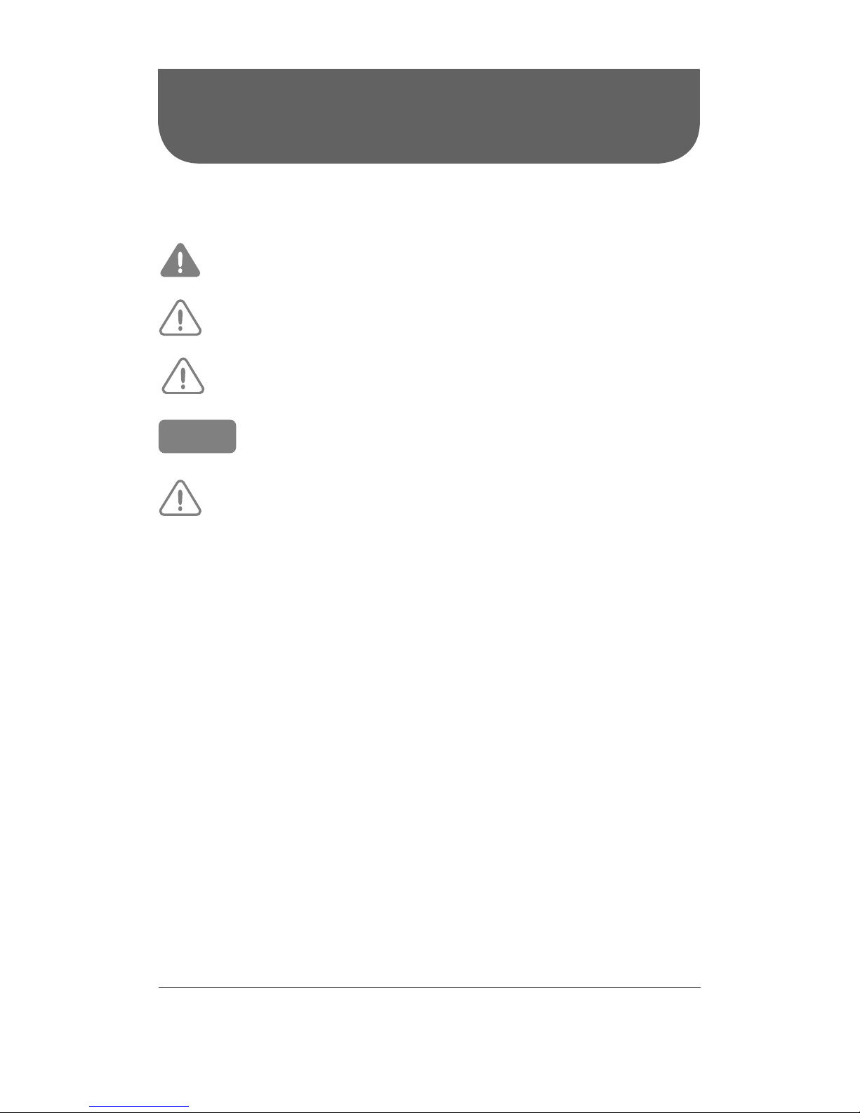
EXPLANATION OF SYMBOLS
Indicates a hazardous situation that, if not avoided,
will result in serious injury or death.
Indicates a hazardous situation that, if not avoided,
could result in serious injury or death.
Indicates a hazardous situation that, if not avoided,
may result in minor or moderate injury.
Indicates important but not hazard-related information,
used to indicate risk of property damage.
Indicates a hazard and it is assigned to the signal words
DANGER, WARNING or CAUTION.
CAUTION
WARNING
NOTICE
DANGER
Page 4

4
USER NOTICES
• The total capacity of the indoor units running at the same time cannot exceed 150% of the outdoor
unit capacity. Otherwise, the cooling or heating effect of each indoor unit will be poor.
• To ensure a successful startup, switch the main power on 8 hours before powering on the unit.
• After receiving the “Off” signal, each indoor unit will continue to operate for 20 to 70 seconds to use the
remaining cool or warm air in the air exchanger while preparing for the next operation. This is normal.
• When the operating mode of the indoor unit is in conflict with that of the outside unit, a malfunction
light will blink for 5 seconds on the indoor unit display or on the controller to warn the user. Then the
indoor unit will stop. Change the operating mode of the indoor unit to match that of the outdoor unit
or with a compatible mode. COOL mode is compatible with DRY mode and FAN mode is compatible
with all operating modes.
• If the supply power fails when the unit is running, the indoor unit will send the “start” signal to the
outdoor unit three minutes after power recovery.
• This appliance is not intended for use by people (including children) with reduced physical, sensory
or mental capabilities, or lack of experience and knowledge, unless they are under the supervision or
instruction concerning use of the appliance by a person responsible for their safety. Children should
be supervised to ensure that they do not play with the appliance.
• This product must not be disposed together with the domestic waste. This product has to be disposed
at an authorized place for recycling of electrical and electronic appliances.
PRECAUTIONS
WARNING
Operation and Maintenance
• This appliance can be used by people (including children of 8 years old and above) with reduced phy-
sical, sensory or mental capabilities, or lack of experience and knowledge, as long as they are under
the supervision or instruction concerning use of the appliance by a person responsible for their safety.
• Children shall not play with the appliance.
• Cleaning and user maintenance shall not be made by children.
• Do not connect to multi-purpose socket. Otherwise, it may cause fire hazard.
• Disconnect power supply when cleaning. Otherwise, it may cause electric shock.
• If the power supply wire is damaged, it must be replaced by a qualified person in order to avoid
a hazard.
• Do not wash with water to avoid electric shock.
• Do not spray water on indoor unit. It may cause electric shock or malfunction.
• After removing the filter, do not touch fins to avoid injury.
• Do not use fire or hair dryer to dry the filter to avoid deformation or fire hazard.
• Do not operate this unit with wet hands.
• Maintenance must be performed by qualified person. Otherwise, it may cause personal injury
or damage.
Page 5

5
• Do not repair the appliance by yourself. It may cause electric shock or damage. Please contact a
qualified person when you need to repair it.
• Do not extend fingers or objects into air inlet or air outlet. It may cause personal injury or damage.
• Do not block air outlet or air inlet. It may cause malfunction.
• When below phenomenon occurs, please turn off the appliance and disconnect power immediately,
and then contact a qualified person for service:
- There’s abnormal sound during operation.
- Circuit break trips off frequently.
- The appliance gives off burning smell.
- Indoor unit is leaking.
• Do not use or place any flammable, combustible or noxious substance next to the unit.
• If the appliance operates in an inappropriate environment or under abnormal conditions, it may cause
malfunction, electric shock or fire hazard.
• Keep good ventilation in the room to avoid oxygen deficit.
• Do not step on top panel of outdoor unit, or put on heavy objects. It may cause damage or personal
injury.
• When the unit is not to be used for a long time, please cut off the main power supply of the unit.
• Before turning the unit off, make sure it has run for a minimum of 5 minutes; otherwise its service life
will be shortened.
WARNING
Wiring
• Installation must be performed by a qualified person. Otherwise, it may cause personal injury or
damage.
• Must follow the electric safety regulations when installing the unit.
• According to the local safety regulations, use qualified power supply circuit and circuit breaker.
• Install a circuit breaker of adequate capacity only used for the system; otherwise, it may cause mal-
function.
• An all-pole disconnection switch having a contact separation of at least 3 mm in all poles should be
connected in fixed wiring.
• The appliance should be properly grounded. Incorrect grounding may cause electric shock.
• Make sure the power supply matches with the requirement of the appliance. Unstable power supply
or incorrect wiring may cause malfunction of the unit, electric shock or fire hazard.
• Properly connect the live wire, neutral wire and grounding wire.
• Be sure to cut off the power supply before proceeding any work related to electricity and safety.
• Do not turn the power on before finishing installation.
• If the power supply or signal control wires are damaged, it must be replaced by a qualified person
in order to avoid problems.
• During installation, the communication cable and the power cord must not be twisted together but
instead separated with an interval of at least 2 cm, otherwise the unit is likely to run abnormally.
• The temperature of refrigerant circuit will be high, please keep the interconnection cable away from
the copper tube.
Page 6

6
• The appliance shall be installed in accordance with national wiring regulations.
• Installation must be performed in accordance with the requirement of NEC and CEC by a qualified
person only.
• The heat pump is a first class electric appliance. It must be properly grounded with specialized groun-
ding device by a qualified person. Please make sure it is always properly grounded, otherwise it may
cause electric shock.
• The yellow-green wire in the appliance is the grounding wire, which can’t be used for other purposes.
• The grounding resistance should comply with national electric safety regulations.
• All wires of indoor unit and outdoor unit should be connected by a qualified person.
• If the length of power connection wire is insufficient, please contact the dealer for a new one. Do not
extend the wire yourself.
• After the electrical installation, take an electric leakage test.
WARNING
Location
• If you need to relocate the appliance to another place, only a qualified person can perform the work.
Otherwise, it may cause personal injury or damage.
• Select a location which is out of reach for children and far away from animals or plants. If it is unavoi-
dable, please add a fence around the outdoor unit for safety purpose.
• The location should be able to withstand the weight of the unit. Otherwise, the unit will fall and it may
cause injury or death.
• Instructions for installation and use of this product are provided by the manufacturer.
Page 7
7
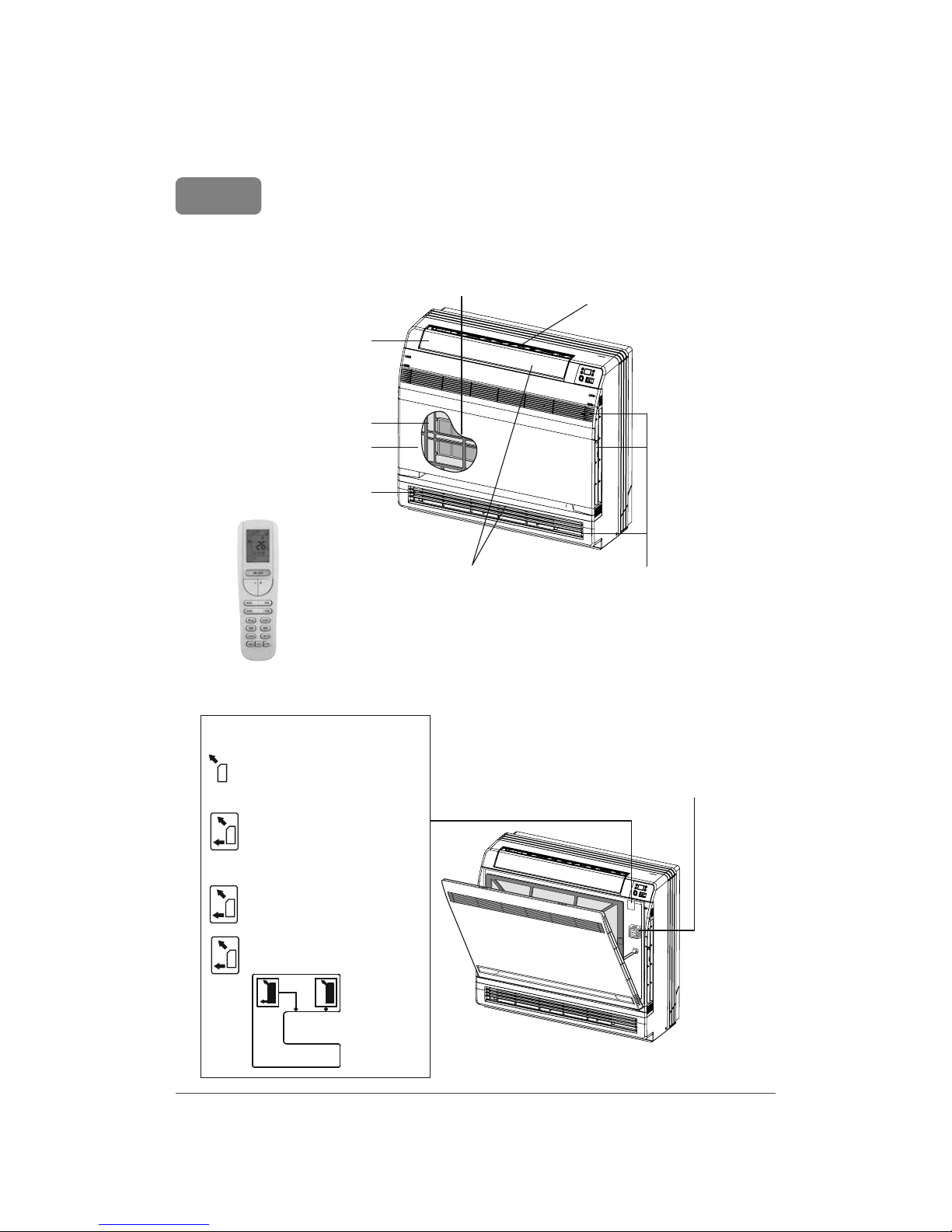
PARTS NAME
Actual product may be different from below graphics, please refer to actual product
for reference purposes.
Indoor unit
Titanium apatite photocatalytic
air-purifying filter
Air outlet
Front panel
Air filter
Flap
(horizontal blade)
Air outlet
Louvres (vertical blades -
inside the air outlet)
Air inlet
Opening the Front Panel
Room temperature
sensor
Air outlet selection button
This setting blows air from
upper outlet only.
This setting automatically
decides a blow pattern
depending on mode and
conditions.
This setting is recommended.
The unit is shipped from the
factory with this setting.
Remote Control
NOTICE
Page 8
8
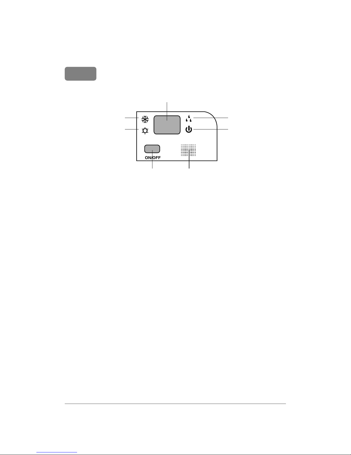
INDOOR UNIT SCREEN DISPLAY
Actual product may be different from below graphics, please refer to actual product
for reference purposes.
COOL mode LED indicator
LED display
Indoor unit
ON/OFF button
Receiving
window
DRY mode LED indicator
HEAT mode LED indicator Power LED indicator
NOTICE
Page 9
9
REMOTE CONTROL
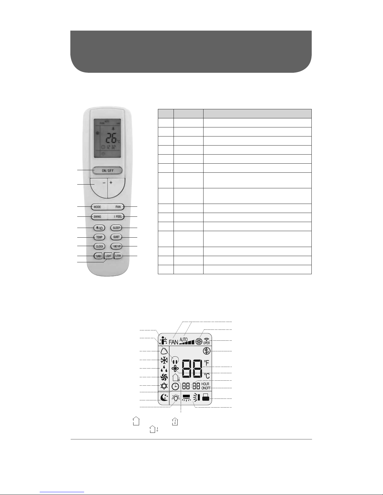
BUTTONS ON REMOTE CONTROL
No. Button Function
1 ON/OFF Turn on or off the unit
2 - / + Set temperature and time
3 MODE Set operation mode
4 FAN Set fan speed
5 SWING Set fan oscillating angle
6 I FEEL Use of the remote control as ambient sensor
7 AIR
Not available on models presented in this
manual
8 SLEEP
Lowering or raising the temperature gradually during the night
9 TEMP Switch temperature displaying type
10 QUIET Set the QUIET mode
11 CLOCK Set up the clock
12
TIMER
ON/OFF
Set starting and ending time
13 TURBO Set turbo fan speed
14 LIGHT Lighted display
15 X-FAN Activation of the AUTO CLEAN function
1
2
34
56
9
7
11
10
8
12
15
13
14
ICON IDENTIFICATION ON REMOTE CONTROL DISPLAY
Fan speed setting
TURBO mode
Working indicator
FREEZE PROTECT mode
Temperature setting
Time setting
TIMER ON / TIMER OFF
Child lock
SLEEP function
Clock
I FEEL function
Up & down swing
Operation mode
AUTO mode
COOL mode
DRY mode
FAN mode
HEAT mode
Temperature display type
Set temperature Indoor ambient temperature
Outdoor ambient temperature
Light
X-FAN function
QUIET function
Page 10

10
OPERATION OF REMOTE CONTROL
NOTES:
• This is a general remote control that could be used for multifunction appliances. If you push a button
which is not featured on the model, the unit will continue to work as is.
• After powering it, the device will beep. Working indicator "
" is activated (in red). After that, you can
operate the unit with the remote control.
• When you are using the remote control for the first time or after replacing batteries, set up the hour
with the button CLOCK.
• In ON mode, when you push a button on the remote control, the icon "
" blinks one time and device
beeps to confirm that the signal has been sent to the appliance.
• In OFF mode, temperature and clock icons will be displayed on the remote control (if functions TIMER
ON, TIMER OFF or LIGHT are activated, they will also be displayed). In ON mode, display will show icons
of chosen functions.
1. ON/OFF button
Pushing this button allows to turn on or off the device.
Working indicator "
" on display of indoor unit will be green when device is turned on and will be red
when it’s turned off.
2. +/- button
Push " + " or " - " button to decrease or increase temperature by 1 degree at a time.
Temperature range is from 16 °C to 30 °C (61 °F to 86 °F).
Maintain " + " or " - " button pushed for 2 seconds in order to change rapidly temperature. Once settings
done, release button and temperature will be modified accordingly (temperature can’t be settled in
AUTO mode).
While adjusting TIMER ON/OFF or CLOCK, push " + " or " - " button to set the time. (Please see section
CLOCK, TIMER ON/OFF buttons for more details.)
3. MODE button
Push this button in order to select operating mode of your choice:
AUTO mode:
When you select automatic mode, the device automatically selects the appropriate function to maintain
temperature between 20 °C and 25 °C (68 °F to 77 °F). In this mode, temperature can’t be changed or
displayed on remote control. When turned on the first time, it works in AUTO mode by default.
COOL mode:
When you select COOL mode, the appliance is cooling the room. Press " + " or " - " to set temperature.
Page 11
11
DRY mode:
When you select DRY mode, the appliance is in dehumidifying mode and works at its lowest speed. In this
mode, the fan speed can’t be changed..
FAN mode:
When you select FAN mode, only the fan is operating. There is no heating, nor cooling in this mode.
HEAT mode:
When you select HEAT mode, device is working on heating mode. Press the " + " or " - " button to adjust
temperature.
NOTE:
• In HEAT mode, the device will delay start-up of the fan to prevent cool air to circulate. This delay can
take up to 5 minutes depending on indoor air temperature.
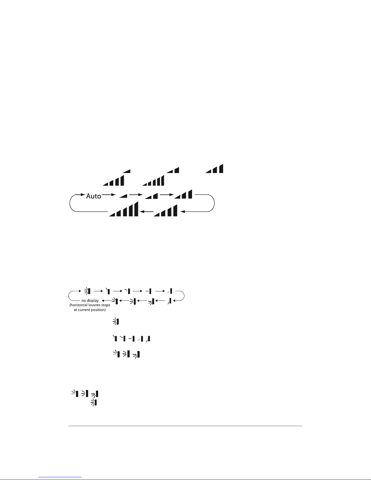
4. FAN button
Push this button to select the fan speed along this sequence:
Automatic (AUTO), low (
), medium-low ( ), medium ( ),
medium-high ( ), high ).
NOTES:
• On AUTO speed, the device will choose ideal speed according to room temperature and set tempera-
ture.
• In DRY mode (dehumidification), fan always goes at low speed.
5. SWING button
Press this button to select oscillating angles for the louvres as per following sequence:
• When selecting " ", horizontal louvre will automatically flip upward and downward at a maximum
angle.
• When selecting "
, , , , ", the device blows air at fixed position. Horizontal louvre will stop
to the chosen position.
• When selecting "
, , ", device blows at fixed position. Horizontal louvre will be at fixed angle.
• Hold the SWING button for 2 seconds to define required oscillating angle. When reached, release the
button.
NOTE:
"
, , " may not be available. When device receives this signal, it will function as per following
position " ".
Page 12

12
6. I FEEL button
Press this button to activate I FEEL function and the icon "
" will appear on remote control. Once this
function is settled, remote control sends the information about room temperature to the control panel
and will adjust automatically. Press again this button to cancel I FEEL function and the icon disappears.
Please put remote control near the user when this function is chosen. Do not put remote control near
something at high or low temperature in order to prevent false results.
Make sure to keep the minimum distance recommended between the remote control and the appliance.
7. AIR button
This function is not available on models presented in this manual.
8. SLEEP button
SLEEP function is available in COOL (cooling), DRY (dehumidifier) and HEAT (heating) modes only. This
function permits to gradually increase or decrease room temperature, so you can save energy without
affecting your sleep. This function is settled over an 8-hour period. After this period of time, the device
will work on previous established parameters, as it was set before SLEEP function was activated.
Press this button to select one of the three SLEEP settings: Sleep 1 (
), Sleep 2 ( ) or Sleep 3 ( ).
The corresponding icon will appear on the remote control.
• Sleep 1:
In COOL or DRY mode:
One hour after activation, the temperature setting will increase of 1 °C (1 °F or 2 °F). After 2 hours,
it will increase of 2 °C (3 °F or 4 °F).
In HEAT mode:
One hour after activation, the temperature setting will decrease of 1 °C (1 °F or 2 °F). After 2 hours,
it will decrease of 2 °C (3 °F or 4 °F).
• Sleep 2:
In this mode, the appliance will run according to a group of preset sleep temperature curves.
COOL mode:
Initial temperature setting between 16 °C to 23 °C (61 °F to 74 °F):
Temperature setting will be increased of 1 °C (1 °F or 2 °F) every hour up to 3 °C (5 °F or 6 °F). One hour
before the end of the SLEEP mode (after 7 hours), the temperature setting will be decreases of 1 °C (1
°F or 2 °F).
Initial temperature setting between 24 °C to 27 °C (75 °F to 81 °F):
Temperature setting will be increased of 1 °C (1 °F or 2 °F) every hour up to 2 °C (3 °F or 4 °F). One hour
before the end of the SLEEP mode (after 7 hours), the temperature setting will be decreases of 1 °C (1
°F or 2 °F).
Initial temperature setting between 28 °C to 29 °C (82 °F to 85 °F):
After one hour, temperature setting will be increased of 1 °C (1 °F or 2 °F) and will be maintained for
6 hours. One hour before the end of the SLEEP mode (after 7 hours), the temperature setting will be
decreases of 1 °C (1 °F or 2 °F).
Initial temperature setting 30 °C (86 °F) or above:
The unit will keep the initial setting. No temperature setting increase.
HEAT mode:
Initial temperature setting 16 °C (61 °F) or below:
The unit will keep the initial setting. No temperature setting decrease.
Initial temperature setting between 17 °C to 20 °C (62 °F to 68 °F):
After one hour, temperature setting will be decreased of 1 °C (1 °F or 2 °F) and will be maintained for
the duration of the SLEEP mode.
Page 13

13
Initial temperature setting between 21 °C to 27 °C (69 °F to 81 °F):
Temperature setting will be decreased of 1 °C (1 °F or 2 °F) every hour up to 2 °C (3 °F or 4 °F) and will be
maintained for the duration of the SLEEP mode.
Initial temperature setting between 28 °C to 30 °C (82 °F to 86 °F):
Temperature setting will be decreased of 1 °C (1 °F or 2 °F) every hour up to 3 °C (5 °F or 6 °F) and will be
maintained for the duration of the SLEEP mode.
• Sleep 3
This SLEEP setting allows you to make your own program. You can program the temperature setting for
up to 4 periods after the activation of the SLEEP function:
• 1 hour
• 2 hours
• 3 hours
• 8 hours
Under SLEEP 3 setting, press the TURBO button for a few seconds until “1hour” is displayed on the
screen. The setting temperature of the last sleeping curve setting will be displayed and will blink.
Press “+” or “-“ button to set the desired temperature.
Press TURBO button to confirm and switch to the next period.
Repeat the previous 2 steps until the desired temperature is set for all 4 periods.
9. TEMP button
When pushing this button, you can choose the temperature you wish to see on the indoor unit display:
set temperature, indoor room temperature or outdoor temperature.
• When " " or “ no display” is displayed, the set temperature is shown.
• When "
" is displayed, indoor room temperature is shown.
• When "
" is displayed, current outdoor temperature is shown.
NOTE:
Current outdoor temperature is not available on all models. In that case, the set temperature is shown.
10. QUIET button
When QUIET function is on, the unit operates at very low speed to lower the sound level at its minimum.
You can also chose the AUTO QUIET function.
Under this function, in HEAT mode, the device will either run at medium or low (QUIET) speed according
to the difference between ambient and set temperature.
In COOL mode, the device will either run at low-medium speed or low (QUIET) speed according to the
difference between ambient and set temperature.
When you press this button, icon "
" (QUIET) appears on the screen. Press the button again to see the
icon (AUTO QUIET) and another time to cancel QUIET function.
Page 14

14
11. CLOCK button
Press this button to set time. Icon "
" on remote control will blink. Within the next 5 seconds, press
button " + " or " - " to set time. With every push on the button " + " or " - ", time increases or decreases by
one minute. Hold this either buttons for 2 seconds in order to change time faster. Press again the CLOCK
button to confirm the hour and come back to normal display.
NOTE:
Clock uses 24-hour mode.
12. TIMER ON/OFF button
This timer function allows you to program the unit while determining when it starts and when it ends.
Before using this function, make sure your unit is set on the right time.
Setting the starting time of the device:
1. Press TIMER ON button.
2. Press " + " or " - " button in order to set the starting time.
3. Press again TIMER ON to confirm time.
Icon " ON " appears and remote control shows current time.
Setting the ending time of the device:
1. Press the TIMER OFF button.
2. Press the " + " or " - " button in order to set the ending time.
3. Press again TIMER OFF to confirm time.
Icon " OFF " appears and remote control shows current time.
To cancel this function, press the TIMER ON and/or TIMER OFF button and corresponding icons will
disappear.
13. TURBO button
When TURBO function is on, the unit operates at super high speed to achieve quick cooling or heating.
This function is available only in COOL (cooling) or HEAT (heating) mode.
When you press this button, icon "
" appears on the screen. Press the button again to cancel TURBO
function.
NOTE:
When TURBO function is activated, fan speed can’t be changed.
14. LIGHT button
Press that button to light the indoor unit display screen. When the light on the display screen is on, icon
"
" appears on the screen.
15. X-FAN button
Press this button to activate the AUTO-CLEAN function. After the heat pump turns off, the fan will continue to operate for 2 minutes in order to dry the indoor unit to prevent mold growth.
This function is available only in COOL or DRY mode.
When you press this button, icon "
" appears on the screen.
Page 15

15
SPECIAL FUNCTIONS
Child lock function
This function eliminates unwanted temperature adjustments and the use of different modes on the
device. Before activating it, make sure to have set the temperature as you like.
Press simultaneously " + " and " - " buttons to activate or deactivate the child lock function. When that
function is activated, icon "
" is displayed on the remote control.
Temperature display in °C or °F
When device is turned off (OFF), press simultaneously on " - " and MODE buttons to switch from °C or °F.
FREEZE PROTECT mode
During winter, FREEZE PROTECT mode allows to maintain room temperature at 8 °C (46 °F) when you are
not at home. When device is in HEAT (heating) mode, press simultaneously on CLOCK and TEMP buttons
to activate this function. Icon " $ " will be displayed. Press again simultaneously on CLOCK and TEMP
buttons to deactivate.
NOTES:
• In FREEZE PROTECT mode, fan speed is set by default to AUTO and cannot be adjusted.
• SLEEP and FREEZE PROTECT mode cannot be activated at the same time.
Page 16

16
REPLACING BATTERIES IN REMOTE CONTROL
1. Lightly press the " " and slide in the direction the arrow
is pointing to remove the back cover of the remote control
(as illustrated).
2. Remove the old batteries (as illustrated).
3. Insert two new " AAA " (1.5 V) dry batteries and make sure
the position of + and – is correct (as illustrated).
4. Put back the cover (as illustrated).
NOTES:
• During operation, point the remote control at the receiving window on the indoor unit.
• The distance between the remote control and receiving window should not be more than
26.25 ft. (8 m) and there should be no obstacle between them.
• The remote control should be placed 3.3 ft. (1 m) away from TV or Audio sets.
• The signal can be easily interfered in a room where there is a fluorescent lamp or wireless phone;
the remote control should be near the indoor unit when operating.
• If the remote control does not operate normally, please take out the batteries and reinsert them
after 30 seconds. If it is still not working, replace the batteries.
• When replacing batteries, use only new and identical ones (same brand).
• When you do not use the remote control for a long time, take out the batteries.
Page 17

17
PREPARATION BEFORE INSTALLATION
INDOOR UNIT INSTALLATION DRAWING
The indoor unit may be mounted in three different ways:
Exposed
Floor lnstallation
Wall Installation
Half conceated
Mounting plate
Grid (field supply)
Molding
Concealed
REQUIRED INSTALLATION CLEARANCE DISTANCES DIAGRAM
59"(150 cm)
or more
59"(150 cm)
or more
59"(150 cm)
or more
59"(150 cm)
or more
6" (15 cm) or below
from the floor
Page 18

18
SELECTION OF INSTALLATION LOCATION
Basic requirements
Installing the unit in the following places may cause malfunction. If it is unavoidable, please consult
a qualified person:
• A place with strong heat sources, vapors, flammable or explosive gas or volatile objects spread
in the air.
• A place with high-frequency devices (such as welding machine, medical equipment).
• A place near coastal regions.
• A place with oil or fumes in the air.
• A place with sulphurous gas.
• Other places with special environment.
• In a laundry room, near a bath, shower or swimming pool.
Note:
The power cords and connection lines of the indoor and outdoor units must be at least 3.3 ft. (1 m) away
from the TV set or radio to avoid image interference and noise ( even if the clearance distance is kept,
noise may be produced due to strong electromagnetic wave).
Indoor unit
• There should be no obstruction near air inlet and air outlet.
• Select a location where the drain pipe can be easily connected to the outside.
• Select a location which is convenient to connect the outdoor unit and which is the closest possible
to the power supply.
• The location should be able to withstand the weight of indoor unit and will not increase noise and
vibration.
• Make sure that the installation follows the requirement of clearance distance diagram.
• Do not install the indoor unit right above an electric appliance.
• The indoor unit should not be exposed to direct sunlight.
• Please try your best to keep the unit away from fluorescent lamps.
Page 19

19
REQUIREMENTS FOR ELECTRICAL CONNECTION
Safety precautions
• You must follow the electric safety regulations when installing the unit.
• According to the local safety regulations, use qualified power supply circuit and circuit break.
• Make sure the power supply matches with the requirement of the device. Unstable power supply
or incorrect wiring may cause malfunction and damage the unit or fire hazard.
• Properly connect the live wire, neutral wire and grounding wire.
• Cut off the power supply before proceeding any work related to electricity.
• Do not turn on the power before finishing installation.
• The temperature of refrigerant circuit will be high, please keep the interconnection cable away from
the copper tube.
• The appliance shall be installed in accordance with national wiring regulations.
Grounding requirements
• The heat pump is a first class electric appliance. It must be properly grounded by a qualified person
with specialized grounding device. Please make sure it is always grounded effectively, otherwise it
may cause electric shock.
• The yellow-green wire in the appliance is the grounding wire, which cannot be used for other
purposes.
• The grounding resistance should comply with national electric safety regulations.
• An all-pole disconnect switch having a contact separation of at least 3mm in all poles should be
connected in fixed wiring.
Page 20

20
INSTALLATION
INSTALLATION OF INDOOR UNIT
Step 1: Install wall-mounting plate (for surface wall installation only)
CAUTION
The mounting plate should be installed on a wall which can support the weight of the indoor unit.
• Referring to drawings below, temporarily secure the mounting plate to the wall; adjust it in horizontal
position with the level meter and then point out the screw fixing holes on the wall.
160 mm
30 mm
30 mm
170 mm
220 mm
120 mm
644 mm
700 mm
200 mm
200 mm
600 mm
570 mm
120 mm
220 mm
Schematic drawing of hooks:
Installation
template
• Drill the screw fixing holes on the wall with the impact drill (the drill head specification should be
the same as the plastic anchor) and then put the plastic anchors in the holes.
• Fix the wall-mounting plate on the wall with tapping screws and then check if the plate is firmly
installed by pulling on it. If a plastic anchor is loose, drill another fixing hole nearby.
Page 21

21
Step 2: Open piping hole
• Choose the position of piping hole according to the direction of outlet pipe.
• Open a piping hole with a diameter of 55 mm in the spot indicated by the symbol “
“ as illustrated
below.
• The location of the hole is different depending on which side is used.
• Allow space around the pipe for an easier indoor unit pipe connection.
• In order to drain efficiently, slant the piping hole on the wall slightly downward to the outdoor side
with a gradient of 5° to 10°.
NOTES:
• Pay attention to dust and take relevant safety measures when opening the hole.
• The plastic anchors are not provided and should be bought locally.
75 mm
75 mm
75 mm
75 mm
75 mm
45 mm
45 mm
45 mm
45 mm
45 mm
350 mm
45 mm
60 mm
Left bottom piping
Refrigerant pipe
Left/right piping
Left back piping
Right back piping
Right bottom piping
Floor
Wall
Wall
5-10
Interior Exterior
Page 22

22
CAUTION
• The suggested shortest pipe length is 8.2 ft. (2.5 m), in order to avoid noise and vibration from the
outdoor unit. (Mechanical noise and vibration may occur depending on how the unit is installed and
the environment in which it is used.)
• See the installation manual of outdoor unit for information on maximum pipe length.
Step 3: Install drain pipe
• Insert supplied drain hose into drain pan socket of the indoor unit and make sure it adheres to the seat
of the socket.
Drain pan
Seal
Drain hose
Drain pan
Seal
• Connect drain pipe to supplied drain hose and bind
the joint with tape.
• Add insulating pipe around the indoor drain hose in
order to prevent condensation.
NOTES:
• Plastic anchors are not provided.
• The diameter of the drain pipe should be larger than or equal to that of the refrigerant pipe. (PVC pipe,
outer diameter: 1 in. (25 mm), wall thickness ≥ 1/16 in. (1.5 mm)).
• The drain pipe should be inclined downward so that water will flow smoothly without any accumu-
lation. There should be no trap as per below image.
100 mm
100 mm
150 mm
Must be no trap
50 mm or more
Vinyl chloride
drain pipe
Reducer
Drain hose
Do not touch water
Drain hose
Insulating pipe
Page 23

23
Step 4: Test drainage system
• Remove the air filters and pour some water into the drain pan to check if water flow goes through
the pipe correctly and observe carefully the joint to see if it leaks or not.
Step 5: Connect the pipe of indoor unit
• To prevent leakage, apply refrigeration oil on both inner and outer
surfaces of the nut. Use refrigeration oil for R410A.
• Aim the pipe joint at the corresponding bell mouth.
• Pre-tighten the union nut with hand.
• Place the open-end wrench on the pipe joint and place the torque wrench on the union nut. Tighten
the union nut with torque wrench. Adjust the torque force by referring to the following table.
• Wrap the indoor pipe and joint of connection pipe
with insulating pipe, and then wrap it with tape.
CAUTION
• Protect the open end of the pipe against dust and
moisture.
• All pipe bends should be as gentle as possible.
Use a pipe tube bender to bend the pipe.
Bending radius should be 1 3/16” (30 mm)
or larger.
Coat here with refrigeration oil
Pipe joint
Union nut
Pipe
Open-end wrench
Union nut
Pipe
Torque wrench
indoor pipe
Hex nut diameter
Tightening torque
(N-m)
Φ 6
15~20
Φ 9.52
30~40
Φ 12
45~55
Φ 16
60~65
Φ 19
70~75
Insulating pipe
Be sure to
place a cap.
If no flare cap is
available,cover
the flare mouth
with tape to keep
dirt or water out.
Page 24

24
Step 6: Insulation of refrigerant pipe
• Refrigerant gas pipe surface temperature can reach 110 °C. Make sure the chosen insulation material
can withstand this temperature.
• Insulating pipe should be made of polyethylene foam with a heat transfer rate of 0.041 to
0.052W/mK (0.035 to 0.045kca/(mh°C).
• Use separate thermal insulation pipes for gas and liquid refrigerant pipes.
• Provide insulation dimensions as per following chart:
Gas side Liquid side
Gas pipe
thermal insulation
Liquid pipe thermal
insulation
O.D. 9.55 mm O.D. 6.4 mm I.D. 12-15 mm I.D. 8-10 mm
Thickness 0.8 mm Thickness 10 mm minimum
Inter-unit wiring
Gas pipe
Liquid pipe
Liquid pipe insulation
Gas pipe insulation
Finising tape
Step 7: Make electrical connections
• Lift the sensor securing plate and remove the front metal plate cover.
• Remove the wire retainer; connect the power connection wire to the wiring terminal according to
the color; tighten the screw and then fix the power connection wire with wire retainer. After finishing
wiring, clamp the grounding wire (yellow-green wire) into the wire-crossing groove as shown in the
following figure, in order to avoid pressing the wire when closing the electric box cover.
Sensor securing
plate
Terminal block
Electrical
component
box
Wire retainer
Front metal
plate cover
Firmly fix the wires with
the terminal screws
Firmly fix the wires
with the
terminal screws
When wire length
exceeds 10m,
use 2.0 mm
diameter wires
Shape wires so
that the front metal
plate cover will fit
securely
Firmly secure
wire retainer
so that wires
sustain no
external stress
Use the specified
wire type
• Put the front metal plate cover and the sensor securing plate back.
Outdoor unit
Indoor unit
Page 25

25
NOTES:
• All wires of indoor and outdoor unit should be connected by a qualified person.
• If the length of power connection wire is insufficient, please contact your dealer for a new one.
Do not extend the wire by yourself.
• A circuit break must be installed in the line. The air switch should be all-pole parting and the contact
parting distance should be more than 3 mm.
Step 8: Bind up pipes
• Bind up the connection pipe, power cord and drain hose with the band.
Connection
pipe
Drain hose
Band
Indoor power cord
Indoor unit
Gas
pipe
Indoor and outdoor
power cord
Band
Drain hose
Liquid
pipe
• Reserve a certain length of drain hose and power cord for installation when binding them.
When binding to a certain degree, separate the indoor power and then separate the drain hose.
• Bind them evenly.
• The liquid pipe and gas pipe should be bound separately at the end.
NOTES:
• The power cord and control wire cannot be crossed or winded.
• The drain hose should be bound at the bottom.
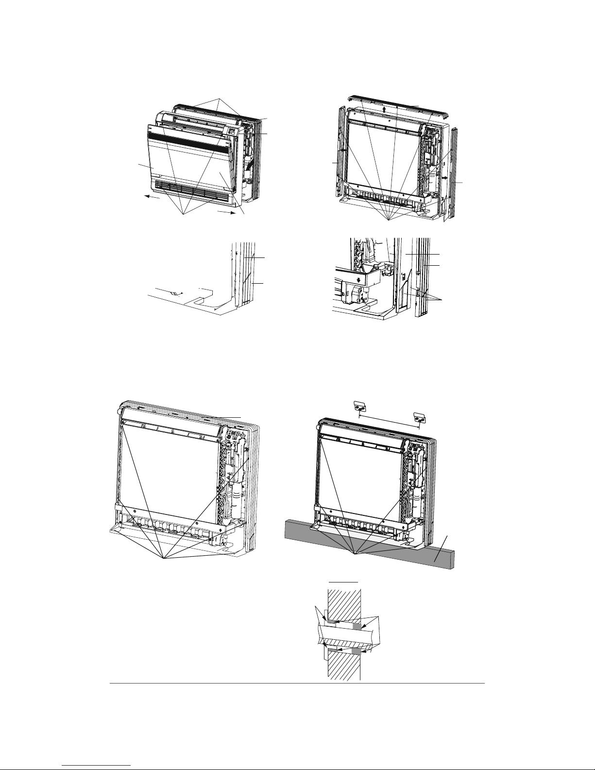
Step 9: Install the indoor unit
• Open the front panel and remove the 4 screws.
• Follow the arrow to disengage the tabs on the casing to remove the front grille.
• Remove the pillars.
• For side piping:
- Remove the 7 screws.
- Remove the upper casing (2 tabs).
- Remove the left and right casings (2 tabs on each side).
• Remove the slit portions on the bottom frame and casings using nippers.
Page 26
26
3 tabs
Open the front panel
Upper casing
Side
casings
Remove the pillar
Remove 4 screws
Remove 7 screws
Casing
Front grille
Casing
Bottom frame
Casing
Remove
the pillar
Remove
the pillar
Side casings
Front
panel
Remove
front grille
• Put the bound pipes in the wall pipe and then make them pass through the wall hole.
• Secure the unit using 6 screws for installation (Do not forget to secure the wall behind).
200 mm
Casing
F
loor Installation Wall Installation
Molding
6 screws
6 screws
• Stuff the gap between pipes and
wall hole with sealing gum.
• Fix the wall pipe.
• Check if the indoor unit is installed firmly
to the wall.
• Install the front panel and front grille back.
Indoor
Wall pipe
Sealing gum
Outdoor
Page 27

27
MALFUNCTION
MALFUNCTION ANALYSIS
Please check below items before asking for servicing. If the malfunction still cannot be eliminated, please
contact a qualified person.
Phenomenon Items to check Solution
Unit doesn’t run
at all.
Circuit break trips off?
Ask a qualified person to replace circuit
break.
Is there a power failure? Wait until power resumes.
Are the electrical connections
properly done?
Ask a qualified person to make proper
connections.
Are the batteries of the remote
control low?
Replace batteries with new ones.
Is the remote control within the
signal receiving distance?
Signal receiving distance is 26.25 ft. (8 m).
Has the unit been turned on immediately after being turned off?
Wait for 3 minutes, and then turn on the
unit again.
Unit runs but stops
immediately.
Are air inlet or air outlet of indoor
or outdoor unit blocked?
Eliminate obstacles.
Abnormal cooling
or heating.
Are air inlet or air outlet of indoor
or outdoor unit blocked?
Eliminate obstacles.
Is the set temperature in proper
range?
Adjust temperature within proper range.
Is fan speed on low setting? Adjust fan setting with the remote control.
Is the SWING setting ok?
Adjust SWING setting with the remote
control.
Are the doors and windows
closed fully?
Close doors and windows.
Is the unit directly under sunlight? Hang curtains or blinds in the windows.
Is there too much heat source or
people in the room?
Unit will run normally once the heat
sources come back to normal.
Is the filter dirty? Clean the filter.
Mist is emitted from
the indoor unit air
outlet.
Are indoor temperature and
humidity level high?
This is because indoor air is cooled rapidly.
After a while, indoor temperature and
humidity level will decrease and mist will
disappear.
Water flowing noise.
Has the unit just been turned on
and off?
The noise is the sound of refrigerant
flowing inside the unit, which is normal.
Cracking noise.
Has the unit just been turned on
and off?
This is the sound of friction caused by
expansion and/or contraction of panel or
other parts due to temperature changes.
Dust is blown from
the unit.
Has the unit been turned on after
a long inactivity period?
Dust accumulation in indoor unit is blown
out by the fan motor.
Odours are emitted.
Is there an odour source in
the room, such as furniture or
cigarette?
Eliminate the odour source.
Is the filter dirty? Clean the filter.
Page 28

28
MAINTENANCE
CLEANING AND MAINTENANCE
WARNING
• Turn off the unit and disconnect the power before cleaning to avoid electric shock.
• Do not wash the unit with water to avoid electric shock.
• Do not use volatile liquid or mineral oils to clean the unit.
• Use suitable instruments for the refrigerant R410A.
• Do not use any other refrigerant than R410A.
Maintenance before seasonal use
• Check if the air inlet/outlet of the indoor unit is clogged.
• Check if circuit breaker and connection are in good condition.
• Check if air filter is clean and well installed.
• To ensure a successful startup, switch the main power on 8 hours before powering on the unit.
Maintenance after seasonal use
• Let the air conditioning unit run for half a day under FAN mode to dry the inside of the unit.
• Disconnect power supply.
• Clean filter and indoor unit.
• If you plan not using the unit on a long period of time, shut down the main power supply for energy
conservation.
Page 29

29
CLEANING THE FRONT PANEL
Step 1: Open the front panel
• Slide the two stoppers on the left and right sides
inward until you hear a “click”.
Step 2: Remove the front panel
• Remove the string to allow the front panel
to fall forward.
• Remove the front panel.
Step 3: Clean the front panel
• Wipe the front panel with a soft cloth lightly moistened with water (below 45 °C).
• Let it dry in a shady and cool place.
Step 4: Reinstall the front panel
• Insert the front panel into the grooves
of the unit (3 places).
• Attach the string to the right inner-side
of the front grille.
• Close the panel slowly.
CAUTION
• Don’t touch the metal parts of the indoor unit. Otherwise, it may cause injury.
• When removing or attaching the front panel, support it with your hand to prevent it from falling.
• After cleaning, make sure that the front panel is securely fixed.
String
String
Place front
panel in
grooves
Page 30

30
CLEANING THE FILTER
The air filter absorbs CO, CO2, benzene, aldehydes, odor of gasoline, etc. It will absorb poisonous material
in the air that is smaller than 1 μm, such as dust, pollen, bacteria and virus.
NOTES:
• Never dismantle the air filter except for cleaning; otherwise it may cause some error.
• The filter should be cleaned every three months. If the unit operates in a highly dusty environment,
cleaning frequency should be increased (generally once every two weeks).
• If it is necessary to change the filter, purchase a new one at your local dealer.
• Do not use fire or hair dryer to dry the filter to avoid deformation or fire hazard.
Step 1: Open the front panel
• Slide the two stoppers on the left and right sides inward until you hear a “click”.
Step 2: Remove the air filter
• Press the claws on the right and left of the air filter down slightly, then pull upward.
• Remove the air purifiers fixed on the filter. Hold the tabs of the frame and remove the claws in 4 places.
Step 3: Clean the air filter
• Use a vacuum or water to clean the filter.
• When the filter is very dirty, use water (below 45 °C) to clean it, and then put it in a shady and cool
place to dry it.
Step 4: Clean the air purifiers
The air purifiers can be cleaned once every 6
months. We recommend replacing it once every
3 years.
• Use a vacuum to remove dust and soak in water
(below 45 °C) for about 10-15 minutes if dirt is
heavy.
Air filter
Titanium apatite
photocatalytic
air-purifying filter
Page 31

31
NOTES :
• Do not remove the air purifiers from their frame when cleaning with water.
• After washing, shake off remaining water and dry in a cool and shady place.
• Since the purifiers are made out of paper, do not wring out the filter when removing water from it.
Step 5: Install the air purifiers and air filter
• Install the air purifiers on the air filter.
• Install the air filter on the unit.
• Close the front panel.
CAUTION
• Operating the unit without air filters may result in troubles as dust will accumulate inside the indoor
unit.
Page 32

32
OPERATION TEST
1. Before operation test
• Ensure that the customer is satisfied.
• Inform the customers about the important notes of the appliance.
2. Operation test
• Put through the power, press the ON/OFF button on the remote control to start the unit.
• Press MODE button to select AUTO, COOL, DRY, FAN or HEAT to check whether the operation is normal
or not.
• If the ambient temperature is lower than 16 °C, the appliance will not work in COOL (cooling) mode.
3. Operating pressure test
• In COOL or HEAT mode, set the temperature to the maximum set point (30 °C or 86 °F).
• Press the TURBO button to activate the fan TURBO speed.
• Wait until the compressor has reached its full speed (15 to 30 minutes).
• Once full speed is reached, take the operating pressure as well as indoor and outdoor temperature.
• Note your results in the table below and keep it for future reference.
Results of the operating pressure test
Operating pressure
Indoor temperature
Outdoor temperature
Page 33

33
NOTES
_______________________________________________________________________________________
_______________________________________________________________________________________
_______________________________________________________________________________________
_______________________________________________________________________________________
_______________________________________________________________________________________
_______________________________________________________________________________________
_______________________________________________________________________________________
_______________________________________________________________________________________
_______________________________________________________________________________________
_______________________________________________________________________________________
_______________________________________________________________________________________
_______________________________________________________________________________________
_______________________________________________________________________________________
_______________________________________________________________________________________
_______________________________________________________________________________________
_______________________________________________________________________________________
_______________________________________________________________________________________
_______________________________________________________________________________________
_______________________________________________________________________________________
_______________________________________________________________________________________
_______________________________________________________________________________________
_______________________________________________________________________________________
_______________________________________________________________________________________
Page 34

34
NOTES
_______________________________________________________________________________________
_______________________________________________________________________________________
_______________________________________________________________________________________
_______________________________________________________________________________________
_______________________________________________________________________________________
_______________________________________________________________________________________
_______________________________________________________________________________________
_______________________________________________________________________________________
_______________________________________________________________________________________
_______________________________________________________________________________________
_______________________________________________________________________________________
_______________________________________________________________________________________
_______________________________________________________________________________________
_______________________________________________________________________________________
_______________________________________________________________________________________
_______________________________________________________________________________________
_______________________________________________________________________________________
_______________________________________________________________________________________
_______________________________________________________________________________________
_______________________________________________________________________________________
_______________________________________________________________________________________
_______________________________________________________________________________________
_______________________________________________________________________________________
 Loading...