

Page 1
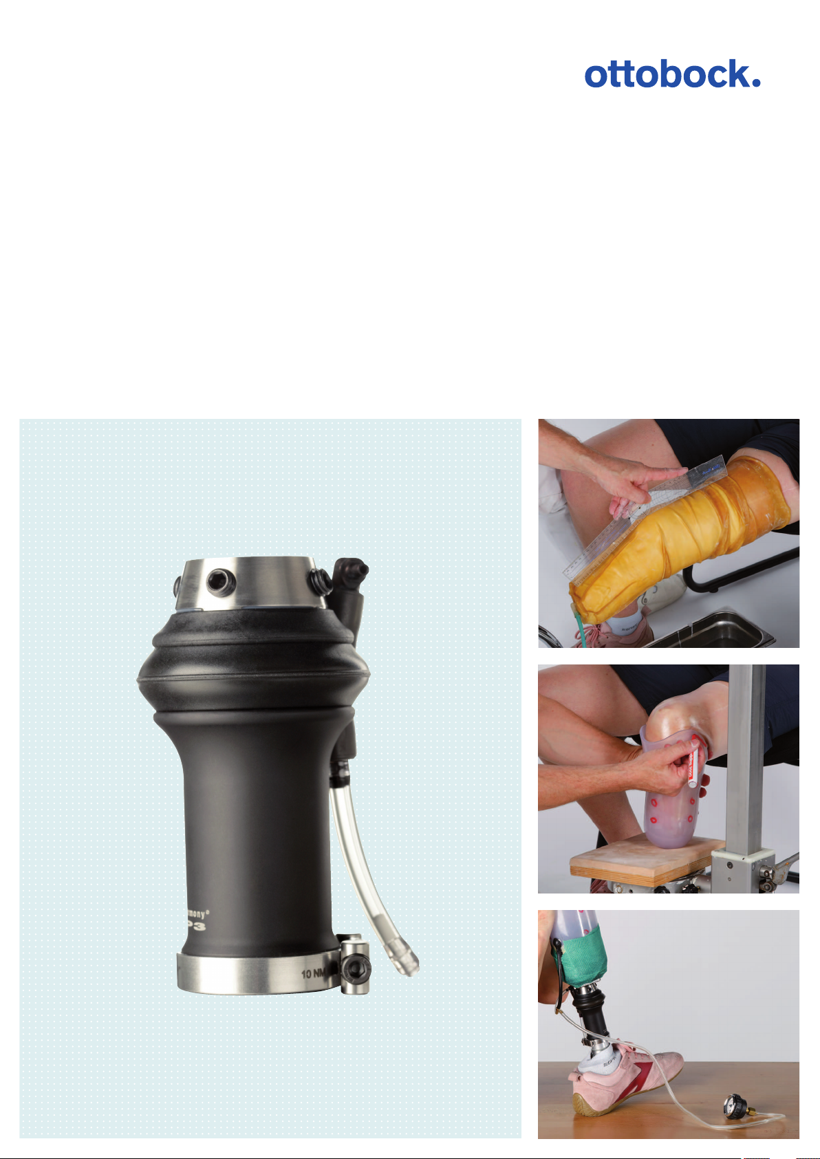
Harmony system
Fabricating a transtibial prosthesis using example of Harmony P3
Technical information 2.1.8
Page 2

Table of contents
Table of contents
Introduction1 3.........................................................................................................................................................
Flowchart1.1 3............................................................................................................................................
Preparation2 3..........................................................................................................................................................
Collecting the materials and tools2.1 4...........................................................................................................
Procedure3 5.............................................................................................................................................................
Selecting the liner3.1 5.................................................................................................................................
Plaster cast3.2 6..........................................................................................................................................
Preparing the Plaster Cast3.2.1 6.....................................................................................................................
Moulding the femoral condyles and tibial plateau3.2.2 7......................................................................................
Moulding the tibia and the head of the fibula3.2.3 8............................................................................................
Moulding the volume3.2.4 9.............................................................................................................................
Fabricating the plaster model3.3 10...............................................................................................................
Fabricating the test socket3.4 12...................................................................................................................
Checking the fit3.5 13..................................................................................................................................
Checking the volume3.5.1 13...........................................................................................................................
Checking the course of the socket brim3.5.2 15.................................................................................................
Aligning the prosthesis3.6 16........................................................................................................................
Attaching the socket connector3.6.1 16.............................................................................................................
Optional: Transferring the adapter position3.6.2 17.............................................................................................
Selecting the functional ring3.6.3 17.................................................................................................................
Replacing the functional ring3.6.4 18................................................................................................................
Dynamic trial fitting3.7 19..............................................................................................................................
Preparation3.7.1 19........................................................................................................................................
Testing the vacuum system3.7.2 19...................................................................................................................
Trial fitting3.7.3 19..........................................................................................................................................
Fabricating the definitive socket3.8 19............................................................................................................
Transferring the adapter position3.8.1 20...........................................................................................................
Vacuum forming3.8.2 20..................................................................................................................................
Laminating3.8.3 21.........................................................................................................................................
Optional: Producing a sleeve protector3.8.3.1 22..................................................................................................
Optional: Attaching a cosmetic cover3.9 23.....................................................................................................
Tips and tricks4 24...................................................................................................................................................
Checking the system4.1 24...........................................................................................................................
Solutions to problems4.2 25..........................................................................................................................
Appendix5 30............................................................................................................................................................
Reduction tables5.1 30.................................................................................................................................
Measurement form5.2 31..............................................................................................................................
2 | Ottobock
Harmony System
Page 3

Introduction
1 Introduction
This technical information supports you in the fabrication of a prosthesis with the Harmony system, a system used
for active generation of a vacuum. The system consists of a vacuum pump, a polyurethane liner, a gel-coated seal
ing sleeve and a total surface weight-bearing socket.
There are both mechanical and electronic Harmony vacuum pumps. In this document, the fitting procedure is
explained on the example of a Harmony P3 vacuum pump. The central work steps can be applied to all Harmony
vacuum pumps. For detailed information, please read the corresponding instructions for use.
This document is intended for certified Harmony experts. It is a prerequisite that the qualified personnel are trained
in the handling of the various materials, machines and tools.
This technical information does not claim to be exhaustive. Reading this technical information does not replace
reading the instructions for use for all required products.
1.1 Flowchart
The entire process is shown in the following flowchart. All work steps described in this document are highlighted in
bold.
Selecting the liner
Fabricating the plaster cast and the plaster model
Fabricating the check socket
Checking the fit
Aligning the prosthesis
Dynamic trial fitting
Fabricating the definitive socket
Attaching a cosmetic cover
Tips and tricks (checking the system, solving problems)
2 Preparation
The following preparations must be made in order to work effectively:
Ottobock | 3Harmony System
Page 4

Preparation
• Collecting the materials and tools
– Components and auxiliary devices
– Materials
– Machines, equipment and accessories
– Tools
• Preparatory work
2.1 Collecting the materials and tools
The materials and tools used in the photos within this technical information are listed in the tables below. The pros
thetist assumes full responsibility for the use of any other materials.
Components and auxiliary devices
Designation Reference number
Harmony P3 4R147*
Liner –
Liner FitKit 451F20
Materials
Designation Reference number
Plastic film –
String –
Nylon tube sock 99B25
Plaster bandages e.g.699G3=*
ThermoLyn soft 616T53=*
Bonding agent 617H46
Wax 633W8
Polyethylene adhesive tape 627B4
Perlon stockinette 623T3=*
Closed-cell foam e.g.: 617S70=4
PVA bag 99B81=70X19X5, 99B81=100X19X5
Pastasil 85H11=*
Carbon fibre cloth strap 616B1=*
Carbon UD stockinette 616G2
Carbon fibre woven stockinette 616G15
Orthocryl lamination resin 80:20 PRO 617H119
Loctite® 241 636K13
Lubricating cream 453H1=1
SensiCare lotion 453H26
Tools
Designation Reference number
Grease pen –
Waterproof marker –
Scissors –
Measuring devices –
Plaster cast scissors –
Latex casting bag 683G1=*
Vacuum pump 755Z19=230
Copying pen 645C2=*
Half-round file 716Y3
Round file 716Y4
Grit cloth 649G22=180
Tensioning frame 755T4=360
4 | Ottobock
Harmony System
Page 5
Procedure
Designation Reference number
Vacuum tube (with vacuum sealing disc) 755X104=360
Vacuum pump 755E9
Torque wrench 710D4
Torque wrench (adjustable to 0.5Nm) –
3 Procedure
3.1 Selecting the liner
CAUTION
Use of an incorrect liner
Skin irritation due to vacuum on the skin
► Only use liners without a textile cover or with a partial textile cover for fittings with the Harmony system.
The selection of the liner is critical for the quality of the fitting. Ottobock recommends only using polyurethane
liners for Harmony systems. There is a choice between standard liners (off the shelf) and custom liners.
Selecting a standard liner
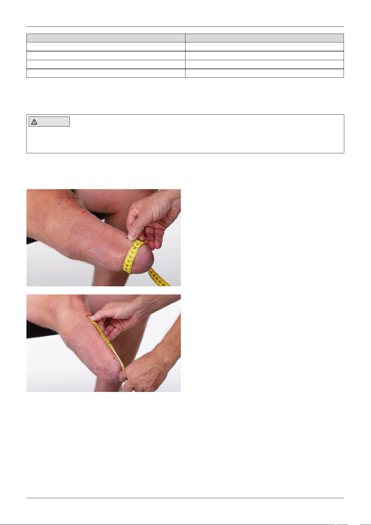
There are various versions of the standard liners. Liners
without pre-flexion are particularly appropriate for cyl
indrical residual limbs. Liners with pre-flexion have an
anatomical shape and are appropriate for short to medi
um length, slightly conical residual limbs.
Liners without pre-flexion
• Measure the residual limb circumference 4cm
above the end of the residual limb.
• Select the next smaller liner size.
Example:
Measured circumference: 250mm, selection: 235mm
Liner with pre-flexion
• Determine the distance between the MPT (mid
patella tendon) line and the end of the residual limb.
• Measure the residual limb circumference 4cm
above the end of the residual limb.
• Select the corresponding length or the next shorter
one.
Example:
Measured length: 125mm, selection: 125mm
Measured length: 135mm, selection: 125mm
• Circumference measured as for liners without preflexion
Ottobock | 5Harmony System
Page 6
Procedure
Ordering a custom liner
Custom liners are custom-produced for the user. This
allows them to meet specific requirements and be
appropriate for all residual limb shapes.
• Determine the necessary measurements on the
patient and fill out the order form for the desired
custom liner (see Page31).
• Take a plaster cast according to the specifications
in the order form.
3.2 Plaster cast
INFORMATION
► Fabricating the plaster cast: Total surface weight-bearing socket, "Harmony" principle
► Shaping the plaster model: Length reduction 5mm to 8mm; global circumference reduction: 4%
3.2.1 Preparing the Plaster Cast
Objective
The liner fit is checked to prepare for the plaster cast. Residual limb dimensions can then be measured and critical
structures on the residual limb marked to facilitate modelling.
Required tools and materials
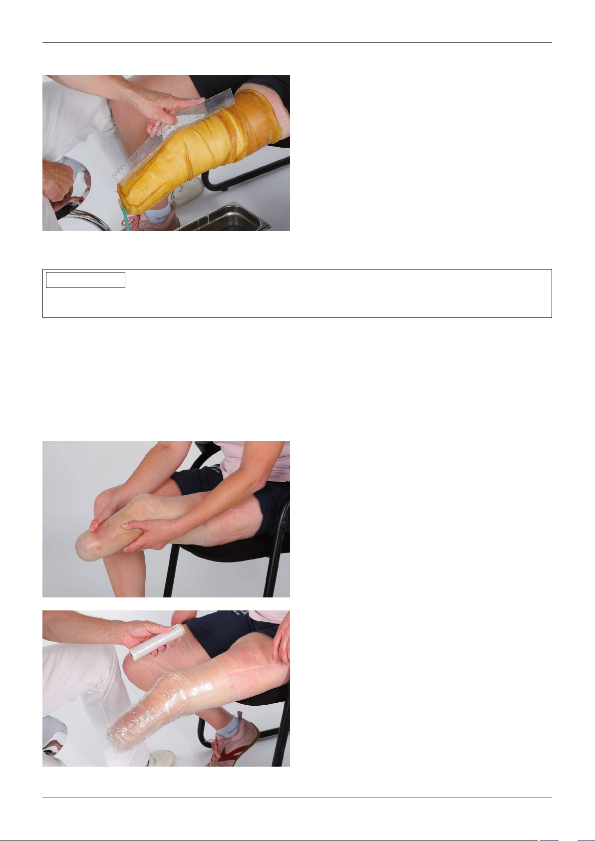
• Grease pen, measuring devices, measurement sheet (see appendices), plastic film, 99B25 nylon stockinette
Roll the liner over the residual limb.
Check the fit.
Work out any air bubbles.
Position the residual limb such that the flexion angle is
approx. 10°.
Determine and document the necessary dimensions
according to your own company's specifications.
Isolate the liner with plastic film up to 5cm below the
edge without changing the shape of the residual limb.
The non-isolated part of the liner supports the connec
tion between the liner and latex casting bag.
6 | Ottobock
Harmony System
Page 7
Procedure
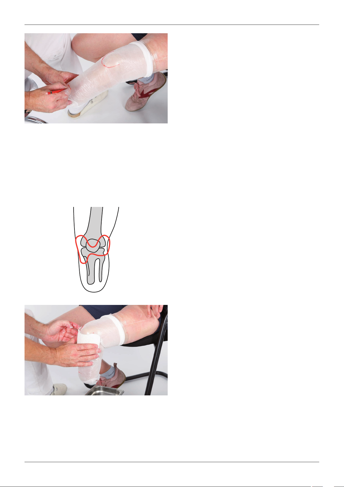
Pull a nylon stockinette over the residual limb.
Optional: Add markings to facilitate modelling, for
example:
• MPT line
• Patella
• Prominent areas of residual limb
• Femoral condyles
• Distal end of the tibia
3.2.2 Moulding the femoral condyles and tibial plateau
Objective
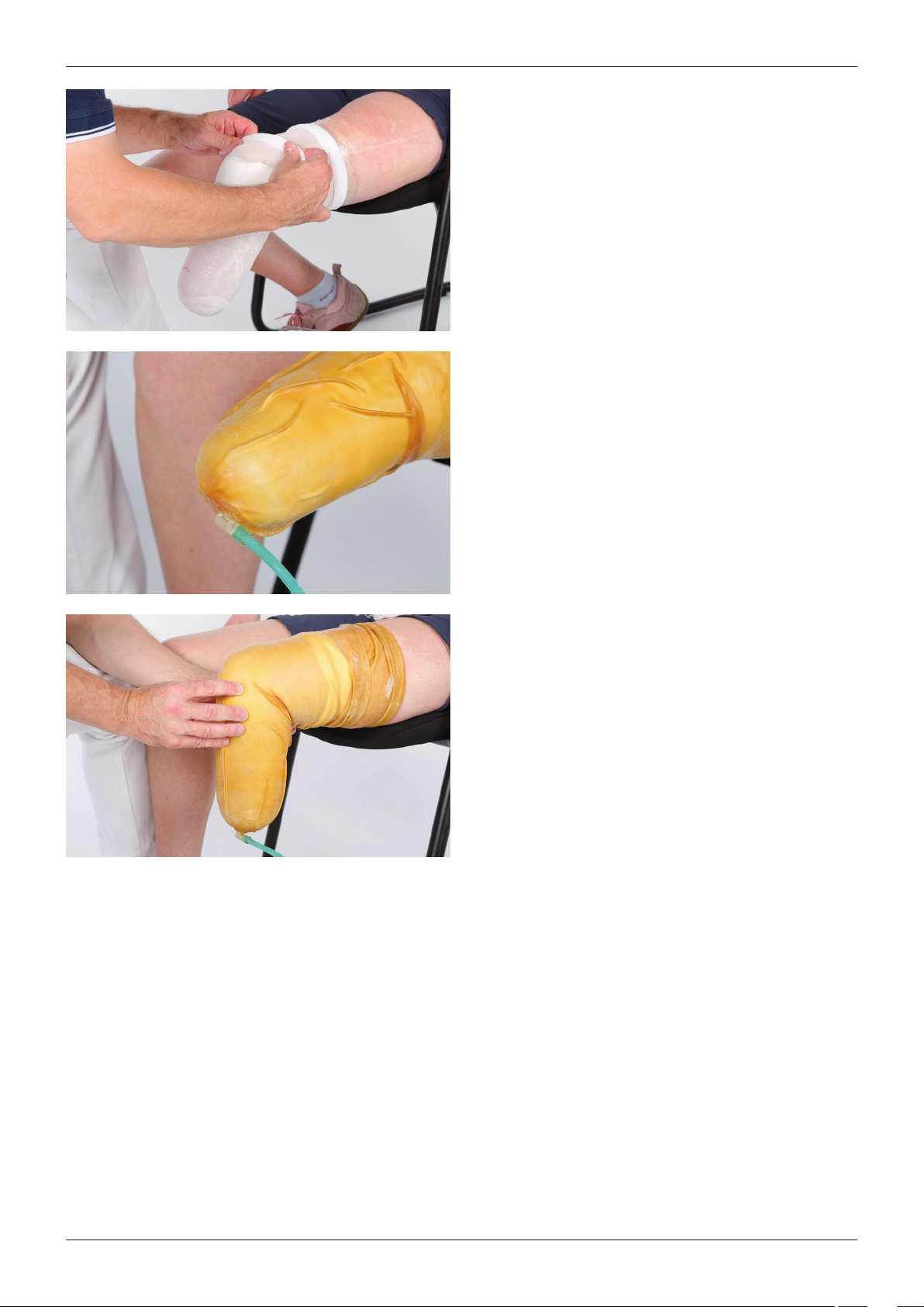
In the first phase of plaster casting the femoral condyles and the tibial plateau are moulded with a plaster splint.
The lower edge of the patella is also formed. The plaster splint is moulded by vacuum in a latex casting bag.
Moulding is carried out at a flexion angle of approx. 85° to enable easy bending of the knee when the prosthesis is
being worn.
Required tools and materials
• Plaster bandages, plaster cast scissors, 99B25 nylon stockinette, 683G1=* latex casting bag
Cut a six-layer plaster splint.
INFORMATION: The plaster splint is part of the plaster
cast and remains in the cast.
Place the plaster splint on the residual limb. Place the
narrow part between the lower edge of the patella and
the tibial tuberosity.
Cut the plaster splint according to the reference points.
Ottobock | 7Harmony System
Page 8
Procedure
Wet the plaster splint and place it on the residual limb.
Pull a nylon stockinette over the residual limb.
Pull a suitable latex casting bag over the plaster cast
and seal proximally.
Connect the vacuum hose and position the distal con
nection of the casting bag on the nylon stockinette.
Position the residual limb such that the flexion angle is
approx. 85°.
Switch on the vacuum pump (vacuum: min. 500mbar).
Mould the lower edge of the patella.
Let the plaster cure.
Hold the plaster splint in place and remove the casting
bag and the nylon stockinette.
3.2.3 Moulding the tibia and the head of the fibula
Objective
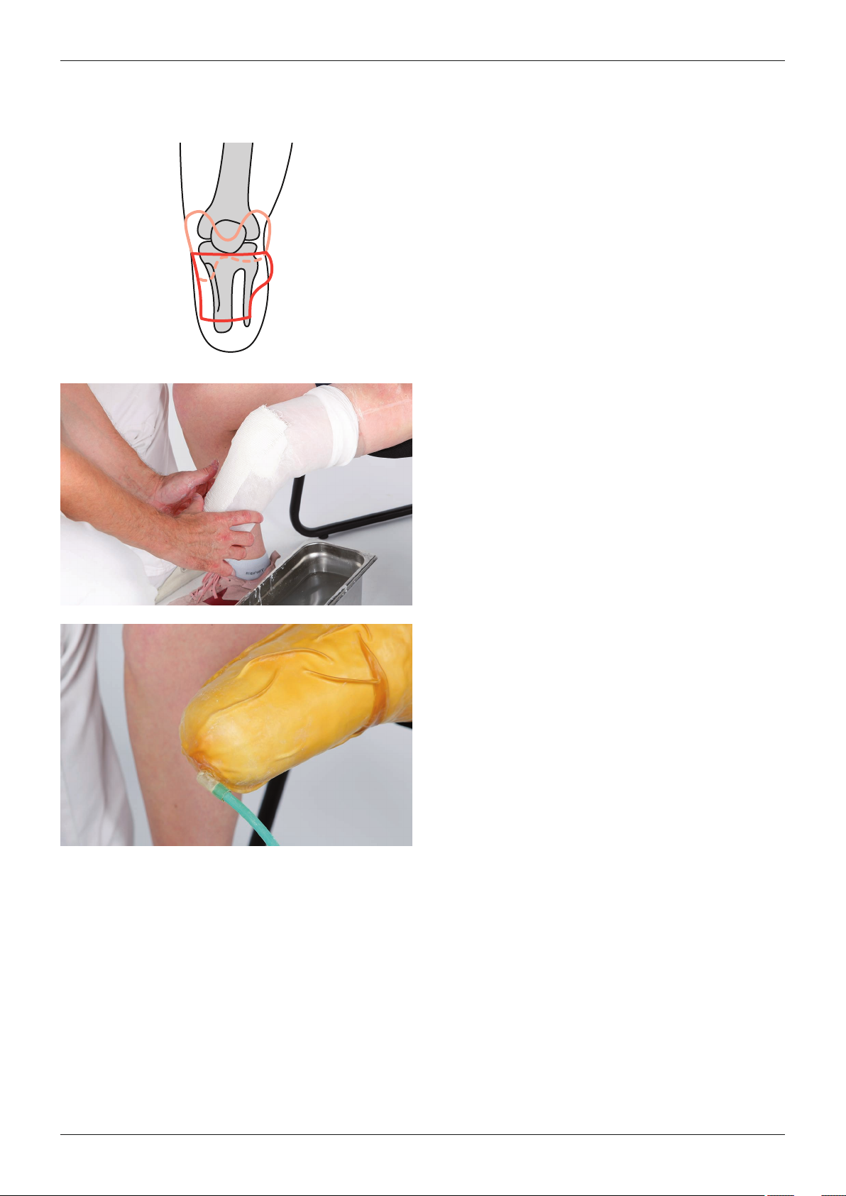
In the second phase of plaster casting the front edge of the tibia and the fibular head are moulded with a plaster
splint.
8 | Ottobock
Harmony System
Page 9
Procedure
Required tools and materials
• Plaster bandages, plaster cast scissors, 99B25 nylon stockinette, 683G1=* latex casting bag, 755Z19=230
vacuum pump
Cut a four-layer plaster splint.
INFORMATION: The plaster splint is part of the plaster
cast and remains in the cast.
Place the plaster splint on the residual limb and ensure
it is seated correctly. The clearance to the end of the
tibia enables correct anterior positioning of the distal
soft tissue.
Wet the plaster splint and place it on the residual limb.
Pull a nylon stockinette over the residual limb.
Pull the latex casting bag over the plaster cast and seal
proximally.
Connect the vacuum hose and position the distal con
nection of the casting bag on the nylon stockinette.
Position the residual limb such that the flexion angle is
approx. 10°.
Switch on the vacuum pump (vacuum: min. 500mbar).
Let the plaster cure.
Hold the plaster splint in place and remove the casting
bag and the nylon stockinette.
3.2.4 Moulding the volume
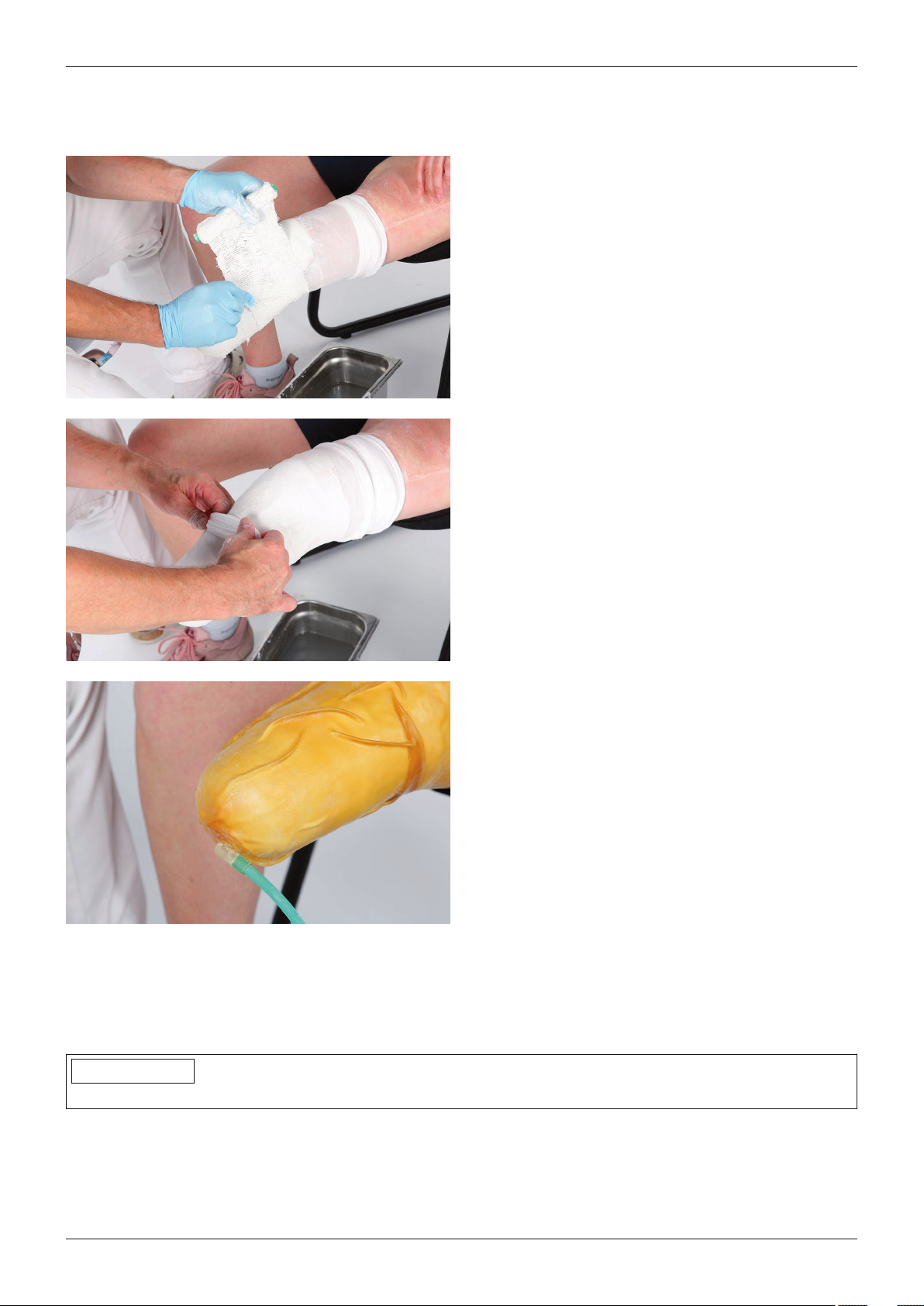
Objective
In the third phase of plaster casting the residual limb volume is formed by wrapping with 2 to 3 plaster bandages.
Ottobock | 9Harmony System
Page 10
Procedure
Required tools and materials
• Plaster bandages, plastic film, 2x 99B25 nylon stockinette or 623T3=* Perlon stockinette, 683G1=* latex cast
ing bag, 755Z19=230 vacuum pump
Instruct the patient to tense the residual limb muscles
briefly. Check the change in shape of the residual limb.
Position the residual limb such that the flexion angle is
approx. 10°.
Wet the plaster bandages and wrap completely around
the residual limb.
Isolate the plaster bandages with plastic film.
Pull two nylon stockinettes or two layers of Perlon
stockinette over the plaster cast, allowing a small
amount to protrude distally.
Pull a suitable latex casting bag over the plaster cast
and seal proximally.
Connect the vacuum hose and position the distal con
nection of the casting bag on the nylon stockinette or
the Perlon stockinette.
Switch on the vacuum pump (vacuum: min. 500mbar).
If the shape of the residual limb changes signific
antly when the muscles are tensed: instruct the
patient to tense and relax the residual limb muscles
alternately while the plaster is curing.
Let the plaster cure.
3.3 Fabricating the plaster model
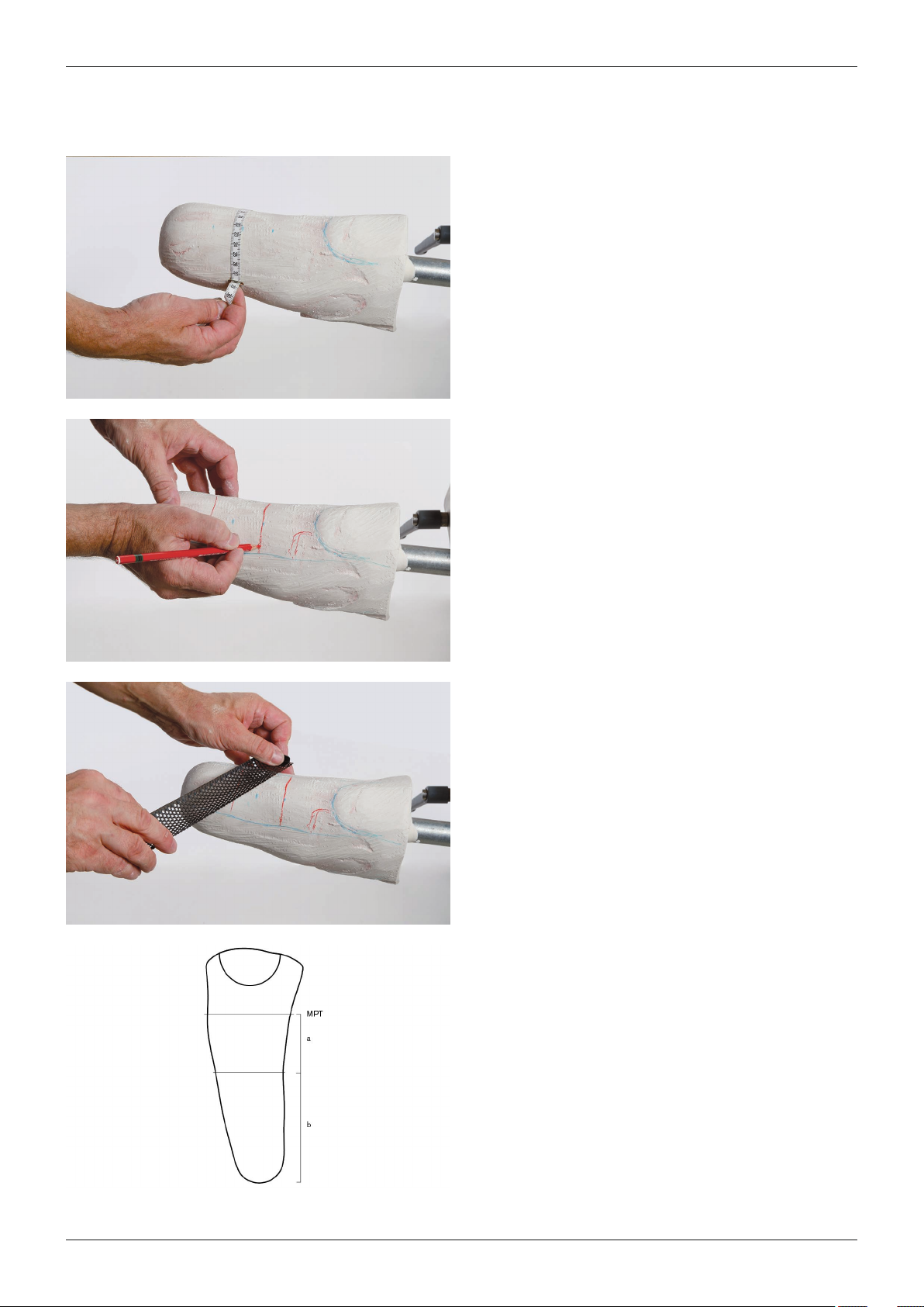
Objective
To fabricate the plaster model, the plaster cast is removed from the residual limb and filled with plaster. The plaster
model is then reduced according to the requirements of the prosthetic socket.
INFORMATION
► Keep the shape of the plaster model unchanged during all reduction steps.
10 | Ottobock
Harmony System
Page 11
Procedure
Required tools and materials
• 645C2=* copying pen, tape measure, measurement sheet and reduction table (see appendices), 716Y3 halfround file, 716Y4 round file, 649G22=180 grit cloth
Remove the plaster cast from the residual limb, fill with
plaster, insert a reinforcing bar and allow the plaster
model to cure.
Identify and mark reference points for the circumferen
tial and length measurements on the plaster model.
Determine the circumferential and length dimensions.
Record the dimensions on the measurement sheet.
Divide the plaster model into four sections (anterior,
posterior, medial and lateral) and mark.
Mark the transitions between convex and concave
shapes with horizontal lines.
Reduce the distal end of the model by 5mm to 8mm
without changing the shape.
If there is overhang of soft tissue, more reduction may
be necessary.
Reduce the circumference of the plaster model globally
by 4% or dependent on the residual limb shape and the
tissue condition.
Reduce the circumference of the plaster model evenly,
dependent on the residual limb shape and the tissue
condition:
MPT: Reduce by 2% to 2.5%
Area a: Reduce by 3% to 4%
Area b:
• Reduce globally by 3% to 5%
Muscular residual limb with firm soft tissue coverage
• Cylindrical residual limb: 4%
• Conical residual limb: 5%
Soft residual limb with easily movable soft tissues
• Cylindrical residual limb: 3% to 4%
• Conical residual limb: 4%
Ottobock | 11Harmony System
Page 12
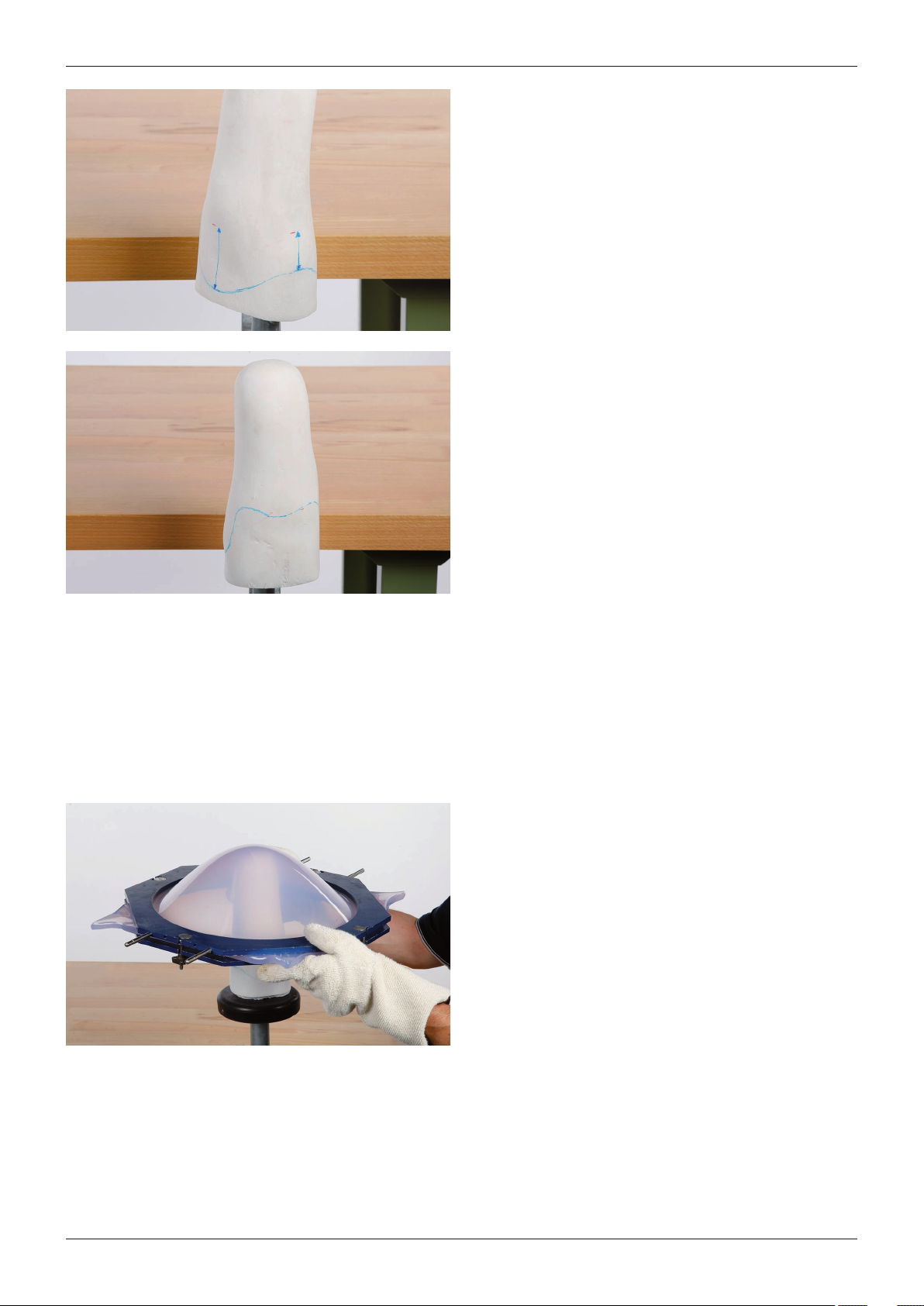
Procedure
Smooth the plaster model.
Mark the course of the socket brim on the plaster mod
el. Use the MPT line as a reference.
• Anteriorly, the edge is located 2.5cm (1") proximal
to the reference line
• Medially and laterally, the edge is located 6cm
(2.5") proximal to the reference line
Create two recesses for the hamstrings in the posterior
socket brim.
• Mark a point 5mm (¼") distal to the reference line
for each hamstring.
• Between the points, the socket brim is located
5mm (¼") proximal to the reference line.
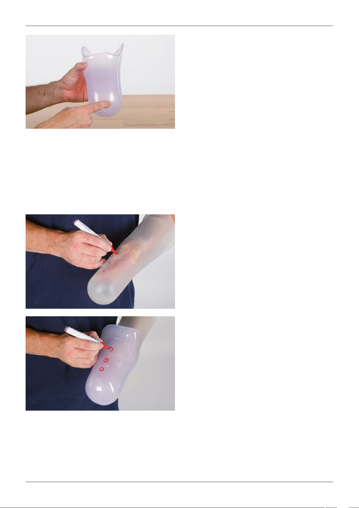
3.4 Fabricating the test socket
Objective
To ensure a good fit, a transparent ThermoLyn check socket is made. It allows the fit to be evaluated, since the col
our of the skin and the flow properties of the liner are visible.
Required tools and materials
• 755T4=360 outer ring, 755X104=360 vacuum tube (with vacuum sealing ring), 755E9 vacuum pump, 99B25
nylon stockinette, ThermoLyn rigid 616T52=* or ThermoLyn clear 616T83=*
Pull a nylon stockinette over the model.
Complete the vacuum forming process with ThermoLyn
rigid or ThermoLyn clear.
Transfer the course of the socket brim to the prosthetic
socket.
Once the material has cooled, cut the prosthetic socket
along the course of the socket brim.
12 | Ottobock
Harmony System
Page 13
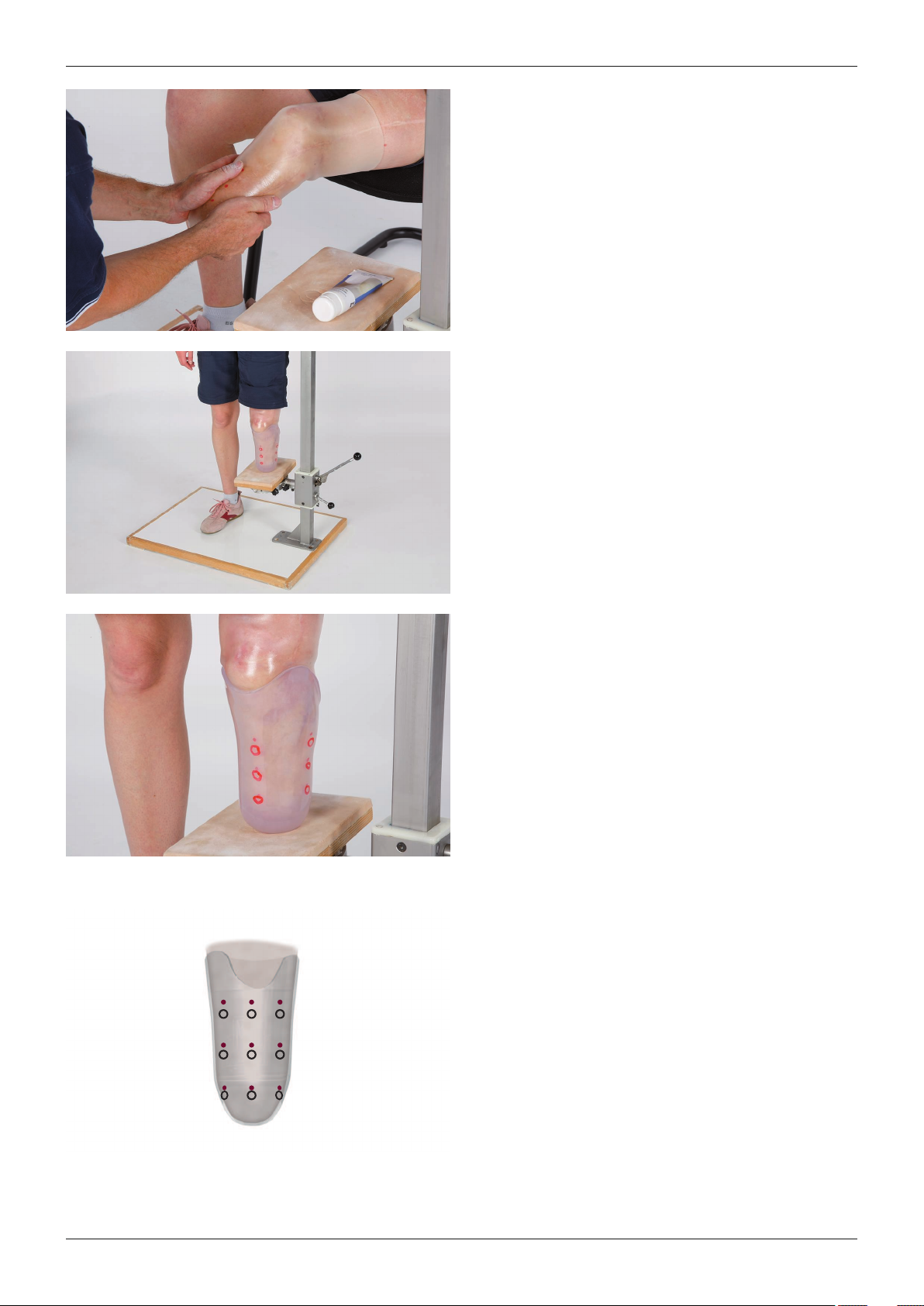
Procedure
Drill a 7.5mm hole in the position where the socket
connector should be attached.
Remove the prosthetic socket from the plaster model.
Deburr the inside and outside of the hole.
Grind and smooth the socket brim of the prosthetic
socket.
3.5 Checking the fit
3.5.1 Checking the volume
Objective
The fit of the prosthetic socket can be seen from the colour of the skin and the flow properties of the liner.
Required tools and materials
• 743A11 plaster device, 451F20 liner FitKit, 616S132 sticky spots, 453H1=1 lubricating cream or 453H26
SensiCare lotion, waterproof marker, check socket, liner
Mark at least three points on each side of the liner
(anterior, posterior, medial, and lateral):
• Vertical: Align the points on an imaginary line and
mark them at identical intervals.
• Horizontal: Mark the points at the same height on
all sides of the liner.
Insert the liner into the prosthetic socket. The distal
hole of the prosthetic socket allows air to escape.
Mark circles encompassing the points on the liner from
outside.
Ottobock | 13Harmony System
Page 14
Procedure
Don the liner.
Apply the lubricating cream to the outside of the liner.
This allows the liner to move in the prosthetic socket.
Don the prosthetic socket.
Ask the patient to stand on the plaster device and dis
tribute the load equally between the prosthetic socket
and the contralateral side.
Check the fit of the prosthetic socket as described in
the following steps. Correct any deviations.
• If the compression is insufficient, the liner FitKit can
be used to compensate for the deviations.
• If the compression is excessive, the thermoplastic
check socket can be heated with a hot air blower
and adapted.
The flow properties of the liner and thus the good fit of
the prosthetic socket are verified by comparing the pos
ition of points on the liner with the circles on the pros
thetic socket.
The points on the liner must move in a proximal direc
tion.
• Horizontal (from the point of view of the indi
vidual rows): The flow properties of the points on
the liner must be identical.
• Vertical (looking at the points in the individual
columns): The distance between the points and the
associated circles must increase from the distal to
the proximal direction.
TIP: Insufficient compression can also be seen from
extended skin redness.
The flow properties of the liner and the fit of the pros
thetic socket are correct.
14 | Ottobock
Harmony System
Page 15
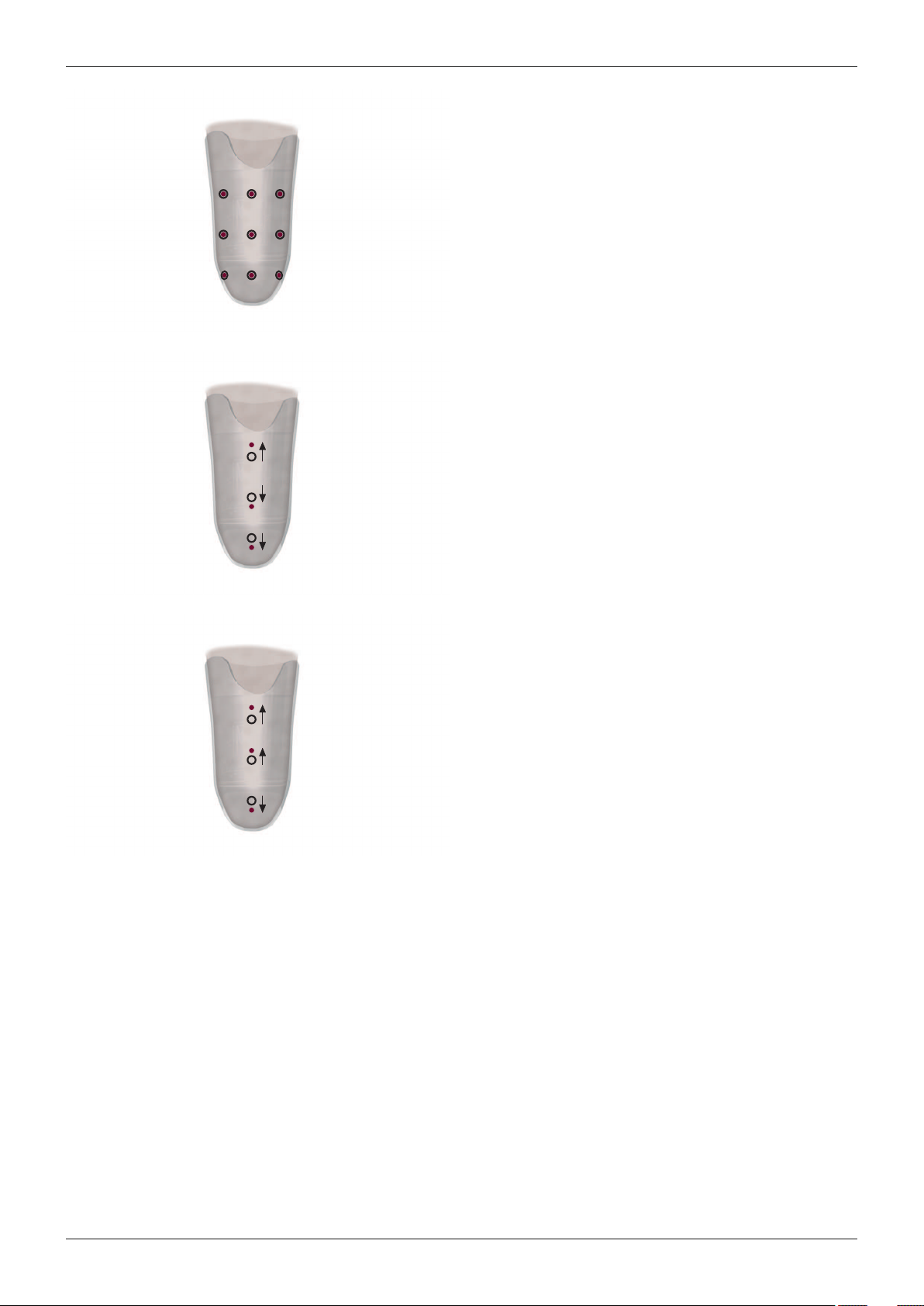
Procedure
If all of the points of the liner are located within the
circles, the liner is not compressed sufficiently.
Put on a residual limb sock from the liner FitKit to
increase the compression.
TIP: If the residual limb sock hides the points on the
liner, wear the residual limb sock under the liner. Only
use this procedure while checking the volume. Then
only wear the residual limb sock over the liner.
The liner flow properties are correct in the proximal
area. The compression is insufficient in the distal and
medial area.
Put on a half residual limb sock from the liner FitKit to
increase the compression in the area.
The liner flow properties are correct in the proximal and
medial areas. The compression is insufficient in the
distal area.
Position a 616S134=* spot from the liner FitKit in the
distal area of the prosthetic socket to increase the com
pression.
Insufficient compression in the lateral area of the pros
thetic socket can be compensated with the 616S132=*
sticky spots.
3.5.2 Checking the course of the socket brim
Objective
The course of the socket brim is critical for a comfortable seating of the prosthetic socket and sealing sleeve. The
socket brim must not be seated to tightly; this can often be evaluated in the a–p direction.
Ottobock | 15Harmony System
Page 16
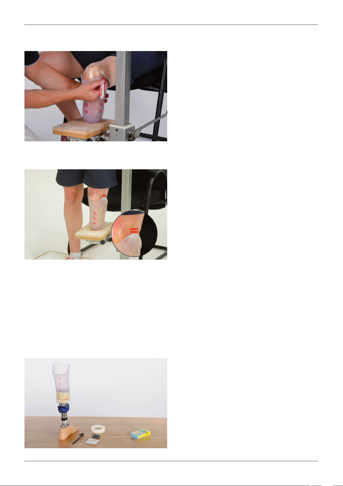
Procedure
Required tools and materials
• 743A11 plaster device, 743L20=230 L.A.S.A.R.-Line, waterproof marker, check socket, liner
Ask the patient to sit down. Position the residual limb in
90° flexion. The distal contact of the residual limb has to
be ensured in the prosthetic socket.
Mark the course of the socket brim:
• There must be sufficient room for the femoral con
dyles during flexion. The medial and lateral socket
brim must not extend over the flexed knee joint so
as not to damage the sealing sleeve.
• Leave a distance of about the width of a finger
between the thigh and the socket brim in the hollow
of the knee.
• Allow the medial and lateral socket brim to fall
steeply in the posterior direction in order not to limit
the knee flexion and avoid the formation of bulges in
the hollow of the knee.
Process the socket brim according to the markings.
Two lines each are marked medially and laterally on the
liner. These lines make it possible to check the volume
even if the prosthetic socket is opaque.
The prosthetic socket is not worn:
• Insert the liner into the socket. Mark one line on the
liner both medially and laterally on the course of the
socket brim.
The patient stands on the plaster device. Equal
load is placed on the prosthetic socket and con
tralateral side:
• Mark one line on the liner both medially and laterally
on the course of the socket brim.
• Mark the plumb line on the prosthetic socket from
the frontal and lateral direction with the L.A.S.A.R.Line.
3.6 Aligning the prosthesis
Objective
Carry out the alignment of the prosthesis according to the instructions for use of the prosthesis components used.
The alignment recommendation (TT modular leg prostheses: 646F336*) can be requested from Ottobock as
needed.
Optional: Use the 4R1 sliding adapter to determine the alignment positions.
Use the L.A.S.A.R.Posture for static alignment of the prosthesis, if available.
3.6.1 Attaching the socket connector
Attach the 2R117=0 socket connector according to the
instructions for use.
TIP: If no PUR adhesive is available, two-component
epoxy adhesive can also be used.
16 | Ottobock
Harmony System
Page 17
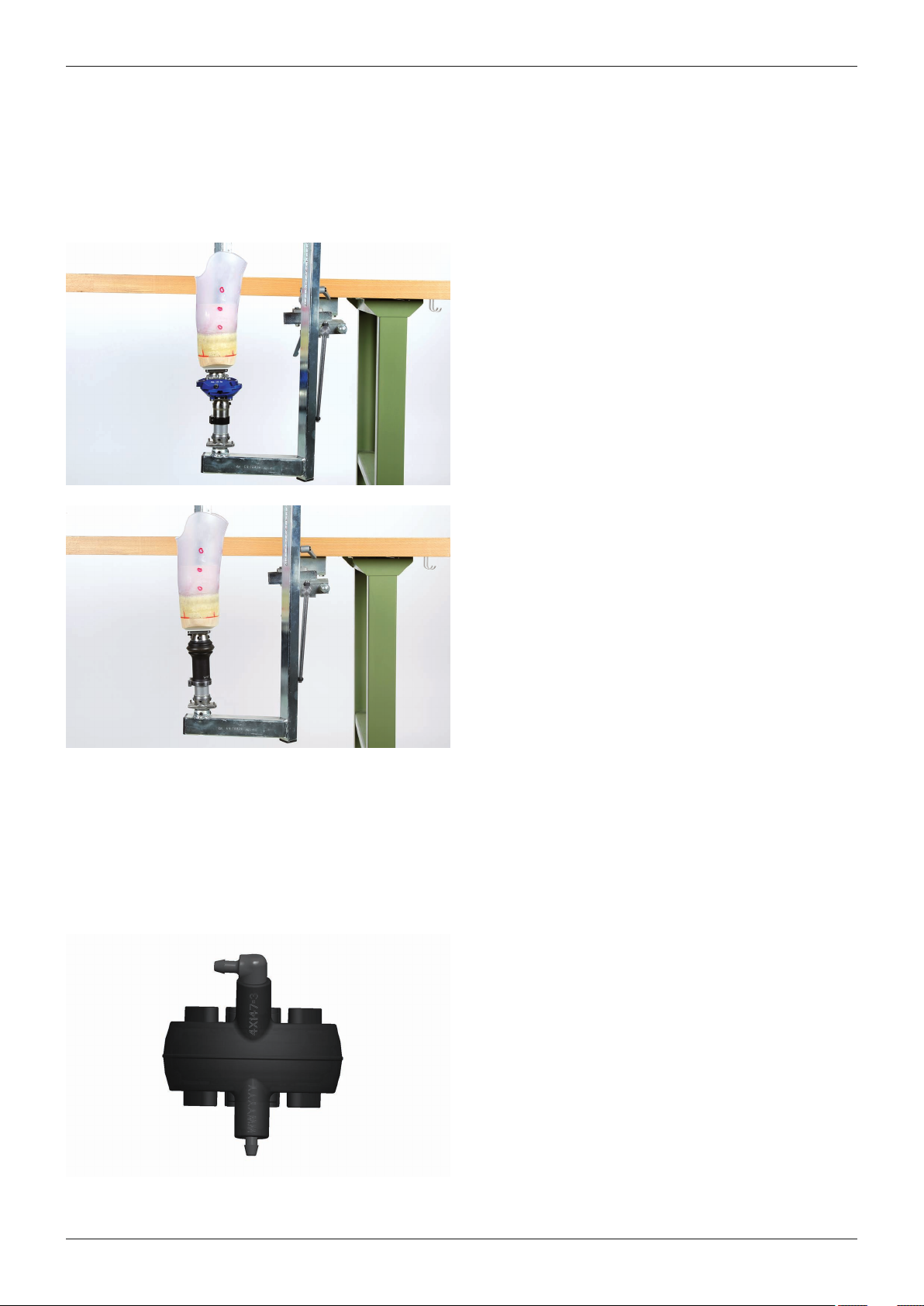
Procedure
3.6.2 Optional: Transferring the adapter position
Objective
If the static alignment was performed without the Harmony P3 unit, the transfer device can be used to transfer the
adapter position to the Harmony P3 unit.
Required tools and materials
• 743A160 transfer device
Determine the adapter position.
Transfer the adapter position to the Harmony P3 unit.
3.6.3 Selecting the functional ring
Objective
To adjust the Harmony P3 unit to the user, various functional rings can be selected. The hardness of the functional
ring affects the vacuum generation and the heel strike with the prosthesis.
Required tools and materials
• Harmony P3 unit, functional rings, 4X247 pre-compression device
Ottobock recommends that vacuum of approx.
500mbar (15inHg) should be reached after 50 steps
with the prosthesis.
Select the appropriate functional ring from the following
table.
If the recommended functional ring does not meet the
requirements, select a different functional ring:
• If the user feels like he or she is sinking into the
prosthesis, the functional ring is too soft.
• If the vacuum generated is insufficient, the function
al ring is too hard.
Ottobock | 17Harmony System
Page 18
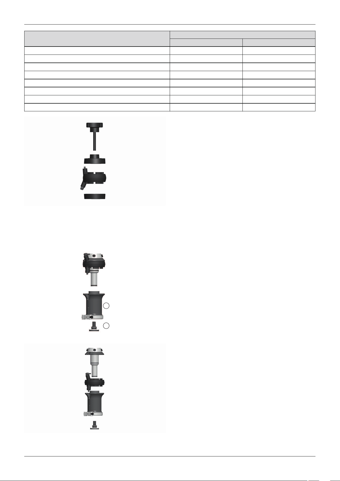
1
2
Procedure
Body weightFunctional ring reference no.
[kg] [lbs]
4X147=0 40 to 47 88 to 103
4X147=1 48 to 55 104 to 121
4X147=2 56 to 65 122 to 143
4X147=3 66 to 75 144 to 165
4X147=4 76 to 87 166 to 192
4X147=5 88 to 100 193 to 220
4X147=6 101 to 112 221 to 247
4X147=7 113 to 125 248 to 276
New functional rings are very stiff. Ottobock recom
mends pre-compression to ensure that they work cor
rectly.
No pre-compression is necessary with the pre-installed
functional ring and with compressed units.
Open the pre-compression device and insert the func
tional ring.
Tighten the screw of the pre-compression device up to
the stop in order to compress the functional ring com
pletely.
Compress the functional ring from at least 3minutes to
at most 15minutes.
Open the pre-compression device and remove the func
tional ring.
3.6.4 Replacing the functional ring
Objective
Loosen the tube clamp of the Harmony P3 unit. Remove
the tube adapter with the prosthetic foot.
Unscrew the retaining screw (1) on the distal end of the
Harmony P3 unit.
Pull the base (2) down distally.
Remove the current functional ring.
Put the new, pre-compressed functional ring on. The
structure of the functional ring only allows attachment in
the correct alignment.
Put the base on.
Secure the retaining screw with Loctite® 241 (636K13)
and screw it in (tightening torque: 7Nm).
Reattach the tube adapter with the prosthetic foot.
18 | Ottobock
Harmony System
Page 19
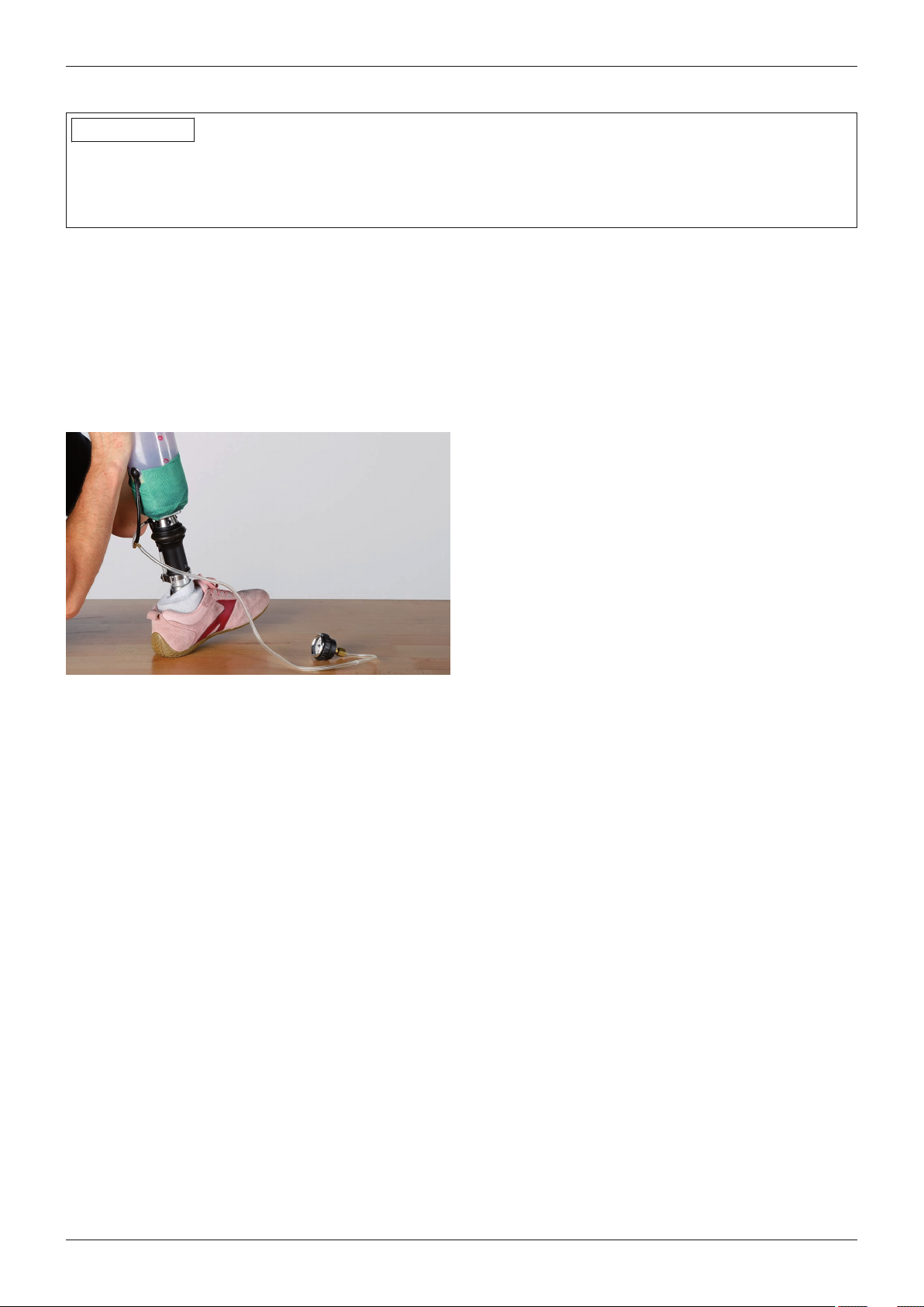
Procedure
3.7 Dynamic trial fitting
INFORMATION
Using the check prosthesis
The user should only use the check prosthesis under the supervision of an orthopaedic technician.
On the basis of his or her professional experience, the orthopaedic technician can decide whether the user can
take the check prosthesis home for an extended trial fitting.
3.7.1 Preparation
Secure the connection between the check socket and
components of the modular system with a stiff bandage
(e.g.Cellacast Xtra 699G30).
3.7.2 Testing the vacuum system
Required tools and materials
• 755Z37 manometer, air-tight adhesive tape,
Connect the manometer to a T-piece.
Seal the hole on the inside of the prosthetic socket with
a piece of paper and air-tight adhesive tape.
Generate vacuum and verify that it is maintained.
If the vacuum is not maintained, check the system with
the help of the troubleshooting table (see Page24).
3.7.3 Trial fitting
Donning the prosthesis
1) Don the liner onto the residual limb.
2) For liners without textile cover: Pull a residual limb sock on.
3) Put on the prosthesis.
4) Pull the residual limb sock or the protruding textile material over the socket brim.
5) Pull the sealing sleeve over.
Dynamic trial fitting
► Perform the trial fitting, verifying the following:
• Seal between socket adapter and prosthetic socket.
• Screw lock and tightening torques.
• Prosthesis fitting with the L.A.S.A.R. Posture, if possible.
Instructing the user
► Instruct the user on the use of the prosthesis. The following are especially important:
• Check the fit of the prosthetic socket every morning on the basis of the mediolateral lines on the liner.
• Feel the vacuum.
• Use the 451F20 liner FitKit.
3.8 Fabricating the definitive socket
Objective
The following section describes the fabrication of the definitive prosthetic socket. The fitting of the check prosthes
is is transferred for the definitive prosthesis. A sleeve protector can be laminated if necessary.
Ottobock | 19Harmony System
Page 20
Procedure
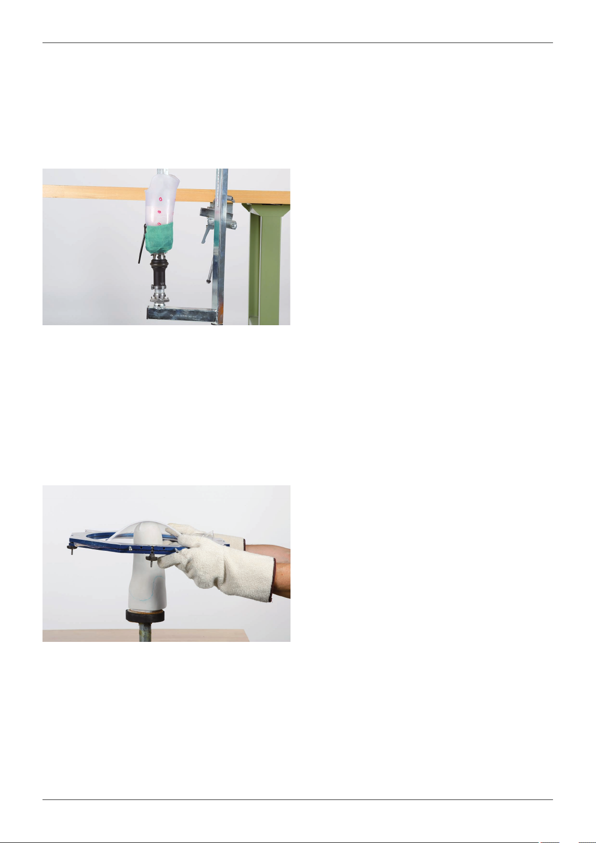
3.8.1 Transferring the adapter position
Objective
The transfer device is used to transfer the adapter position from the check prosthesis to the definitive prosthesis.
The check socket is then filled with plaster and adapted to the plaster model.
Required tools and materials
• 743A160 transfer device, oscillating saw, tape measure, 716Y3 half-round file, 716Y4 round file, 649G22=180
grit cloth
Remove all parts used for the check socket of the liner
FitKit.
INFORMATION: If more than three parts from the
liner FitKit were used for the check socket, a new
check socket should be made.
Transfer the adapter position of the check prosthesis to
the transfer device.
Fill the check socket with plaster to secure the vacuum
pipe.
Remove the plaster model from the check socket.
Prepare the plaster model for the lamination process.
Reduce the plaster model according to the parts of the
liner FitKit used:
• Thick residual limb sock: Reduce the circumfer
ence by 5mm
• Spot: Reduce the plaster model locally by 2mm
3.8.2 Vacuum forming
Objective
A layer of ThermoLyn PETG is vacuum formed over the plaster model as the inner wall of the prosthetic socket. The
ThermoLyn PETG reduces the risk of leaks in the prosthetic socket.
Required tools and materials
• 616T483=3 ThermoLyn PETG
Complete the vacuum forming process with ThermoLyn
PETG.
Cut off material protruding over the model with a knife.
TIP: Further information on vacuum forming with PETG
can be found in the 646T4=1.0 technical information.
20 | Ottobock
Harmony System
Page 21
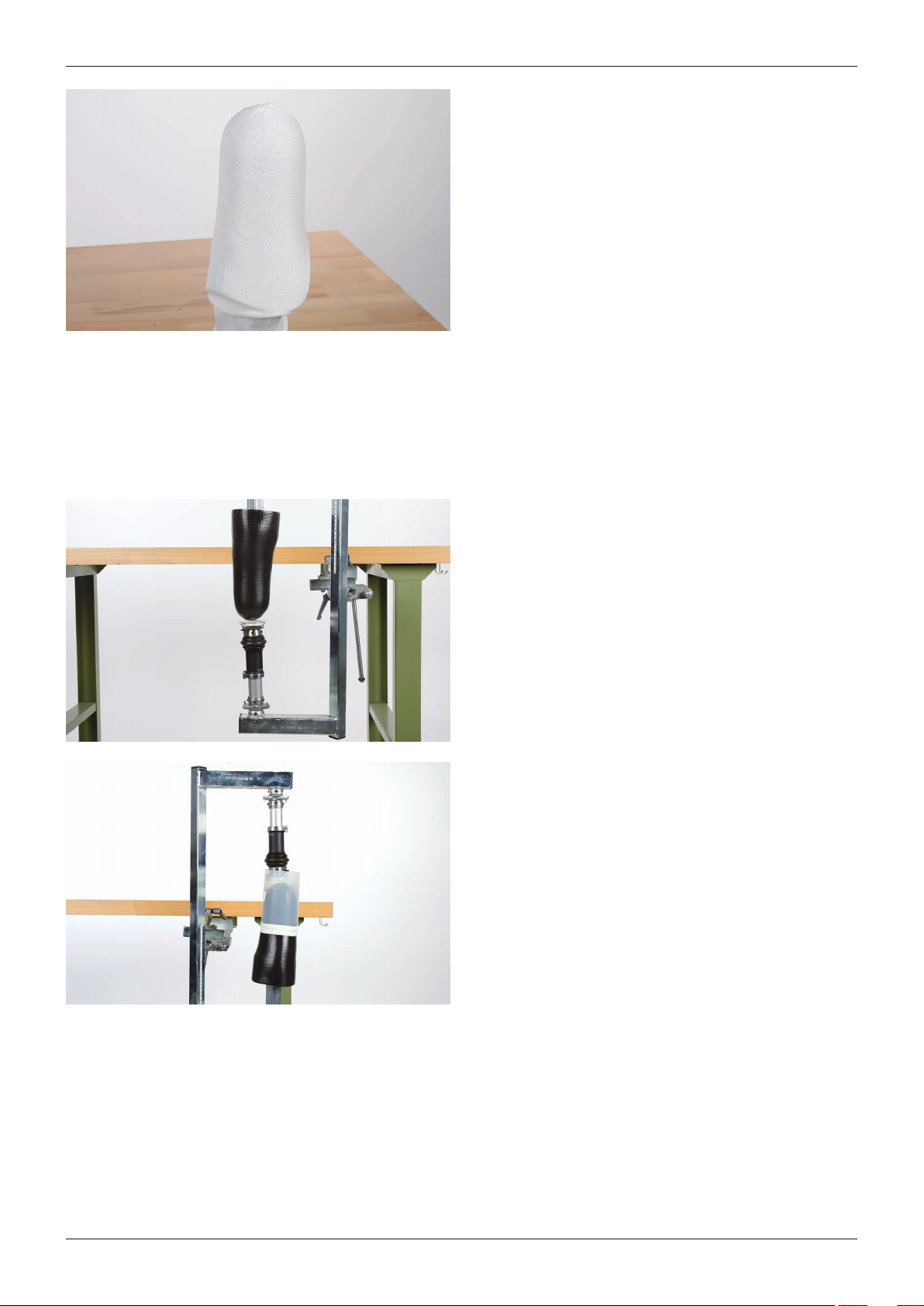
3.8.3 Laminating
Objective
The ThermoLyn PETG layer is laminated with carbon.
Required tools and materials
• 616T483=3 ThermoLyn PETG
Procedure
Roughen the plastic with sandpaper and clean with iso
propyl alcohol.
NOTE: Do not use acetone or thinners. These sub
stances damage the plastic.
Carry out the first lamination process.
Clamp the plaster model with the laminate into the
transfer device.
Establish the connection between the prosthetic socket
and the prosthesis components (e.g.with a sealing res
in/talcum mixture or hard foam)
Carry out the second lamination process.
If a sleeve protector is to be produced: Produce the
sleeve protector before cutting the prosthetic socket
(see Page22).
Cut the course of the socket brim.
Ottobock | 21Harmony System
Page 22
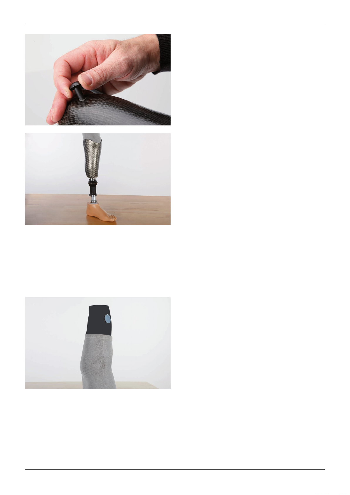
Procedure
Attach the 2R117=0 socket connector according to the
instructions for use.
TIP: If no PUR adhesive is available, two-component
epoxy adhesive can also be used.
Check the system for leaks (see Page19).
Instruct the user in the proper and safe use of the
product.
3.8.3.1 Optional: Producing a sleeve protector
Ottobock recommends using a sleeve protector which protects the sealing sleeve from punctures and creates a
cosmetically attractive closure. It does not protect against friction between the sealing sleeve and socket brim.
Required tools and materials:
• Laminated prosthetic socket, hook-and-loop pads, 623T1* cotton stockinette, 623T3* Perlon stockinette,
623T9* Nylglas stockinette, 616B17* carbon fibre cloth, 99B81* PVA bag, 627B40 polyethylene adhesive tape,
80:20 PRO 617H119 Orthocryl lamination resin
Pull a damaged or worn sealing sleeve over the pros
thetic socket. The end of the sealing sleeve should
extend 5cm (2") past the socket brim in the distal dir
ection.
Place the hook-and-loop pads medially and laterally on
the distal area of the prosthetic socket.
22 | Ottobock
Harmony System
Page 23
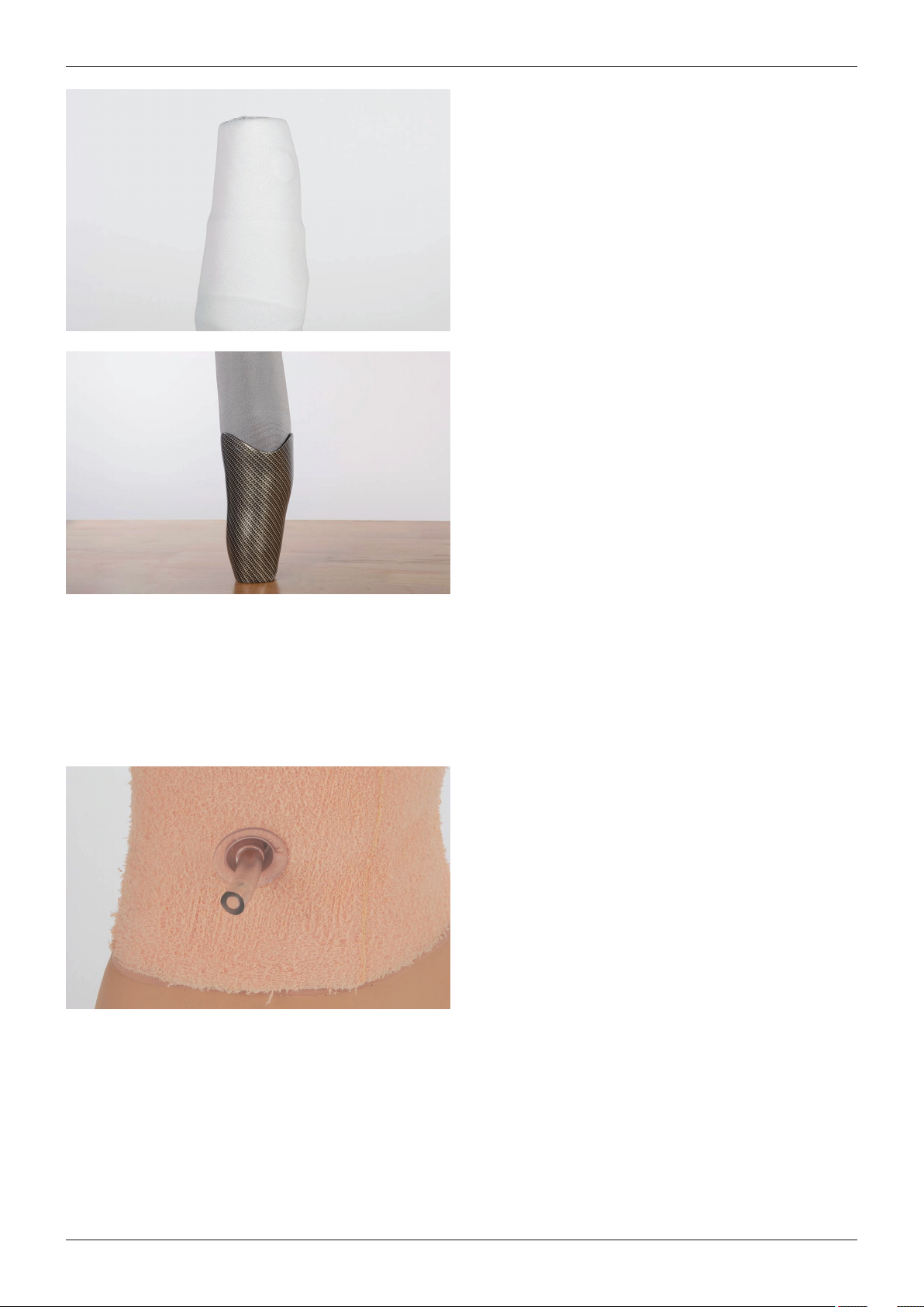
Procedure
Pull four layers of cotton stockinette over the prosthetic
socket.
Pull over one PVA bag.
Pull over one layer of Nylglas stockinette.
Position one layer of carbon fibre cloth
Pull on two layers of Perlon stockinette
Perform the lamination process with Orthocryl.
Cut the sleeve protector off flush with the prosthetic
socket.
Take the sleeve protector off the prosthetic socket.
Cut the course of the edge of the sleeve protector:
• Medial, lateral: 0.5cm to 1cm (¼" to ½") above
the socket brim
• Posterior: 0.5cm (¼") below the socket brim
Smooth the edges carefully.
3.9 Optional: Attaching a cosmetic cover
Objective
A foam cover can be used as a cosmetic cover. Correct attachment ensures the function of the Harmony P3 unit.
Required tools and materials:
• Foam cover with 34mm opening, silicone spray, Superskin or 99B116* SoftTouch sock
Cut the foam cover so it is not crushed.
Grind the contour of the foam cover.
INFORMATION: Use silicone spray to eliminate
noises. Talcum impairs the function of the vacuum
pump.Pull the foam cover over the prosthesis and per
form the fitting.
Do not bond the foam cover to the prosthetic foot.
Position the discharge flange (Ottobock recommends a
medial position at ankle height) and bond it to the foam
cover.
Form the closure with Superskin or a SoftTouch sock.
Ottobock | 23Harmony System
Page 24
1
2
3
Tips and tricks
4 Tips and tricks
4.1 Checking the system
This section gives a methodical troubleshooting procedure for when the vacuum system leaks.
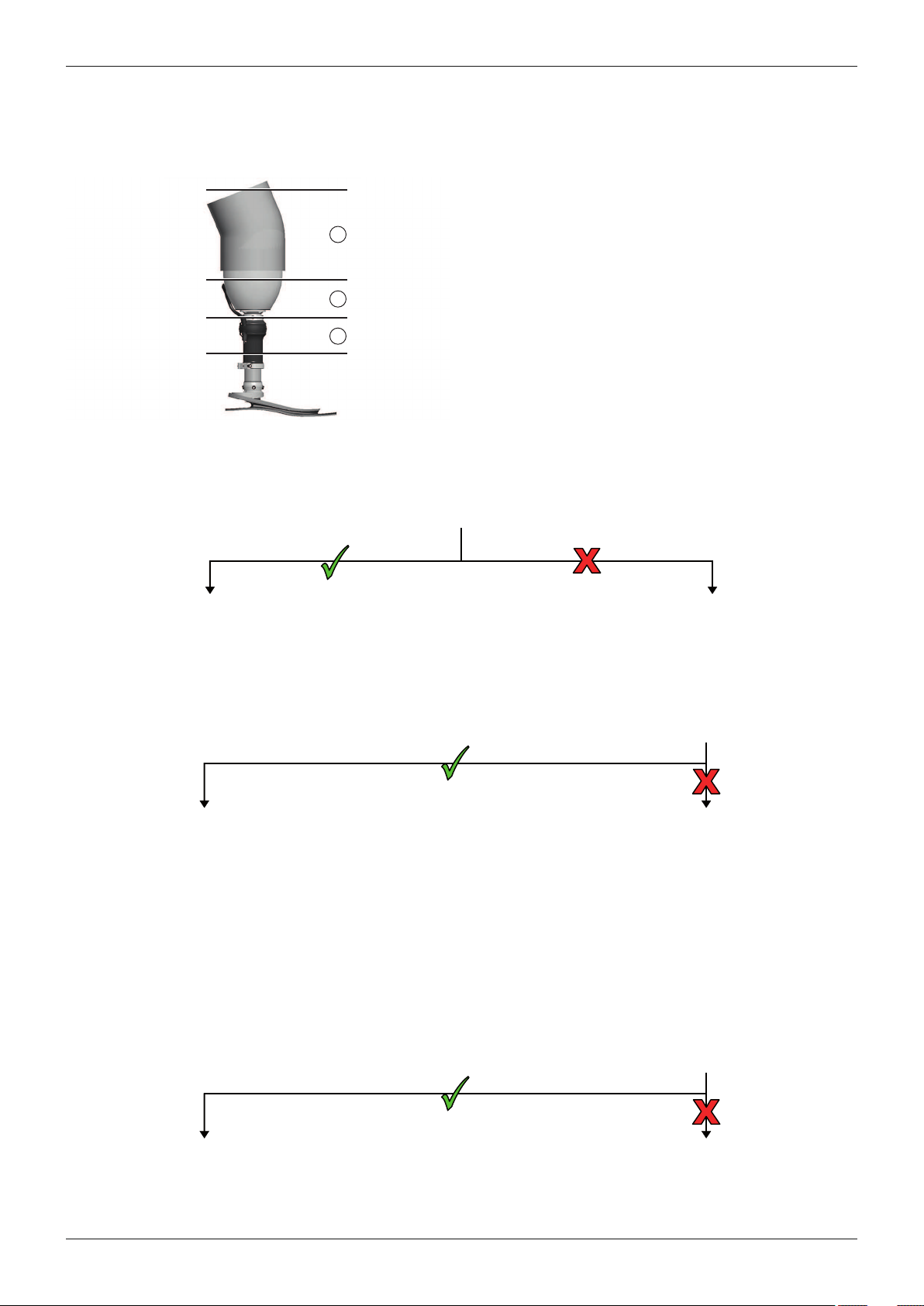
To check the system for leaks, the prosthesis is divided
into areas.
• Area 1: Prosthetic socket and sealing sleeve
• Area 2: Socket connector and connection to the
vacuum pump
• Area 3: Vacuum pump (valves or functional ring)
Seal the outlet opening on the inside of the prosthetic socket with a small piece of paper and air-tight adhesive
tape (e.g. PVC tape).
• Activate the vacuum pump until vacuum of 500hPa to 850hPa is reached.
• Check whether the vacuum is maintained.
The fault is in area 1.
• Check the prosthetic socket and sealing sleeve for
leaks and fix the fault.
The fault is in area 2.
• Place the manometer with a T-piece between the
socket connector and the vacuum pump.
• Seal the hole on the inside of the prosthetic socket
with a piece of air-tight adhesive tape. This is how
the hose connection and the socket connection are
checked.
• Activate the vacuum pump until vacuum of 500hPa
to 850hPa is reached.
• Check whether the vacuum is maintained.
• If the vacuum is maintained, reseal the socket con
nector with adhesive. Then recheck the system.
The fault is in area 2 or 3.
• Connect the manometer directly to the suction con
nection of the vacuum pump.
• Activate the vacuum pump until vacuum of 500hPa
to 850hPa is reached.
• Check whether the vacuum is maintained.
The fault is in area 3.
• Replace the valves of the vacuum pump.
• Check again whether the vacuum is maintained.
The fault has been fixed. The functional ring is defective.
24 | Ottobock
• Replace the functional ring.
Harmony System
Page 25

4.2 Solutions to problems
Topic: Knee
Problem Cause Solution
Knee flexion difficult
or bulging in the hol
low of the knee
Medial and lateral socket brim
runs too far in the posterior
direction.
This squeezes the liner and the
extremity.
Prosthetic socket too tight in
a–p direction.
Posterior socket brim too low.
Bulging because the socket brim
is too low.
Posterior socket brim too
high.
The socket brim hits the hollow
of the knee during flexion.
User wears too many long
residual limb socks.
Relief areas are not aligned
with the knee flexor tendons.
Sealing sleeve too small.
Plaster cast was produced
with 2-phase technique.
The condyles do not have
enough space during knee flex
ion.
Anterior socket edge too high.
This limits the stretching of the
sealing sleeve.
• Cut socket brim so it no longer runs so far in the
posterior direction.
• Extend a thermoplastic check socket accordingly.
• Reduce the plaster model in the transition between
the MPT level and area a less.
• Leave the posterior (w-shaped) socket brim as high
as possible without impeding the knee flexion. Cut
out the socket brim that one finger fits in between
during 90° flexion with the flexor tendons tensed.
• If the user must wear more than one long residual
limb sock to compensate for the volume loss, a new
prosthetic socket should be made.
• Palpate the tensed knee flexor tendons and adapt
the shape of the recesses in the socket brim. The
tendons should be located in the lower area of the
recesses.
• Select a larger sealing sleeve. The sealing sleeve
must enclose the proximal area of the prosthetic
socket and the liner tightly without impeding knee
flexion.
• Make a new plaster cast according to the instruc
tions of this document.
• Form the socket brim to a height where at most the
distal third of the patella is covered.
Tips and tricks
Topic: Residual limb
Problem Cause Solution
Red marks on skin
Loss of vacuum.
Without vacuum, pistoning
occurs in the prosthetic socket,
causing skin irritation.
Specific weight bearing sock
et.
High area-specific compressive
loads due to the socket shape.
Residual limb is pulled into an
area of the prosthetic socket
without load.
The limb shifts in the liner.
• Ensure that the vacuum is generated and main
tained. Without vacuum, the user loses residual limb
volume every day.
• Instruct the user how to check whether there is
vacuum. Instruct the user how to reestablish vacu
um.
• Make a new prosthetic socket according to the
instructions of this document.
• The prosthetic socket must have contact across the
entire surface. No relief should be incorporated.
• If possible, compensate for a volume loss with a
distal spot/half residual limb sock. Use of long sock
can cause the limb to hang proximally and create a
distal void.
• See table section "Shifting in the liner".
Ottobock | 25Harmony System
Page 26

Tips and tricks
Topic: Residual limb
Problem Cause Solution
Red welt on the skin
at top of the liner
User wears liner with textile
cover.
• Only use liners without textile or with partial textile
cover.
The textile cover prevents the
seal between the liner and seal
ing sleeve. This causes the vacu
um to extend up to the thigh,
forming welts on the skin.
Residual limb sock reaches at
least to the upper edge of the
liner.
• Instruct the user to pull the residual limb sock up to
only about 5cm below the edge of the liner. This
allows the seal between the liner and sealing sleeve.
This has the same effect as
wearing a liner with a textile cov
er.
Blisters on the skin Liner not put on correctly.
The air between the liner and the
residual limb was not removed
when it was put on. This is the
most frequent cause of blisters.
Liner or sealing sleeve is too
• Explain to the user how to properly remove all air
from the liner when putting it on.
• When using a PU standard liner: Ensure that the
liner is seated correctly along the entire residual
limb and the thigh.
• Use a PU custom liner to ensure a correct fit.
loose on the thigh.
Air gets under the liner.
Skin in distal region
white and thickened
Insufficient end contact of the
residual limb in the prosthetic
socket.
This generates pressure that is
too low in the distal region.
• Compensate for the lack of residual limb contact
with one or more distal spots or a half residual limb
sock.
• If the skin has thinned again after a few weeks and
returned to a normal colour: Check whether a new
prosthetic socket needs to be made.
Pressure in the distal
region
Volume loss in the distal
region.
The volume loss creates an area
without load. The vacuum pulls
the liner and the residual limb
into a gap and creates a feeling
of pressure in the user. This feel
ing is frequently misinterpreted
as contact in the prosthetic sock
et.
• If the medial and lateral markings on the liner have
slipped into the prosthetic socket, the residual limb
has lost volume.
• Ensure that the vacuum is generated and main
tained. Without vacuum, the user loses residual limb
volume every day.
• If there is vacuum: Compensate for the volume
loss with a distal spot/half residual limb sock until
the marks on the liner are located at the height of
the socket brim again.
• If the distal fillers increase the feeling of pres
sure: The residual limb has probably lost overall
volume; see next table row.
Volume loss on the entire
residual limb.
The volume loss has caused the
residual limb to slip deeper into
the socket, and the end of the
residual limb now bears the
majority of the body weight.
• Remove the distal fillers again.
• Pull a long residual limb sock under the thin residual
limb sock.
• If the markings on the liner become visible and
the pressure abates: Put on another distal
spot/half residual limb sock to prevent the long
residual limb sock from hanging and creating an
area without load.
• If more than three fillers are used, a new prosthetic
socket should be made.
Pressure in the prox
imal area
Volume loss in the distal
region.
The volume loss creates an area
without load. The residual limb
hangs proximally in the prosthet
ic socket, which causes the
• Ensure that the vacuum is generated and main
tained. Without vacuum, the user loses residual limb
volume every day.
• If there is vacuum: Compensate for the volume
loss with a distal spot/half residual limb sock before
putting on the thin residual limb sock.
26 | Ottobock
Harmony System
Page 27

Topic: Residual limb
Problem Cause Solution
Pressure in the prox
imal area
pressure in the proximal area.
The vacuum pulls the liner and
the residual limb into a gap
distally and also creates the feel
ing of pressure.
The proximal pressure is usually
the dominant sensation.
User wears too many long
residual limb socks.
The residual limb hangs proxim
ally in the prosthetic socket due
to the increased volume.
• Remove all fillers.
• Compensate for the volume loss with distal spots
and half residual limb socks until the markings on
the liner become visible and the pressure abates.
• If the distal fillers do not produce a perfect,
comfortable fit: Pull a long residual limb sock over
the liner and compensate again with distal spots
and half residual limb socks.
• If more than three fillers are used, a new prosthetic
socket should be made.
Prosthetic socket too tight.
• Make a new prosthetic socket according to the
instructions of this document.
Pressure on the head
of the fibula
Area around the head of the
fibula moulded incorrectly.
Either too much reduction or
• Modify the check socket in the area of the head of
the fibula thermoplastically.
• Alternatively: Make a new plaster cast.
incorrect moulding occurred.
This applies especially to the
area of the head of the fibula,
because the nerve behind it can
be irritated.
Volume loss on the residual
limb.
The residual limb has lost volume
and slipped deeper into the
prosthetic socket. This causes
the head of the fibula to press
against the lower edge of the
recesses in the prosthetic sock
et.
• If the medial and lateral markings on the liner have
slipped into the prosthetic socket, the residual limb
has lost volume.
• Ensure that the vacuum is generated and main
tained. Without vacuum, the user loses residual limb
volume every day.
• If there is vacuum: Compensate for the volume
loss with a distal spot/half residual limb sock until
the marks on the liner are located at the height of
the socket brim again.
• Try pulling a long residual limb sock over the liner. It
may be necessary to remove distal fillers.
Cramp
ing/aching/throbbing
while standing or sit
ting
Prosthetic socket too tight
overall.
User wears too many long
residual limb socks.
• Make a new prosthetic socket according to the
instructions of this document.
• Remove all long residual limb socks.
• Compensate for the volume loss with distal
spots/half residual limb socks until the markings on
the liner become visible.
• If the distal fillers cause pressure in the distal
area: Try pulling a long residual limb sock over the
liner. It may be necessary to remove distal fillers.
User did not tense the calf
musculature during moulding
of the volume.
• Enclose the user's residual limb with both hands
and ask him or her to tense his or her calf muscu
lature.
If this significantly changes the residual limb
shape: Make a new prosthetic socket according to
the instructions of this document.
Tips and tricks
Ottobock | 27Harmony System
Page 28

Tips and tricks
Topic: Residual limb
Problem Cause Solution
Cramp
ing/aching/throbbing
while standing or sit
ting
Inadequate blood flow to the
residual limb.
• Go through the "Pressure in the proximal area" sec
tion of this table to rule out squeezing in the proxim
al area.
• If the prosthetic socket has the correct fit: Consult
the attending physician to rule out ischaemia, for
example.
Topic: Liner
Problem Cause Solution
Liner tears
Incorrect prosthetic socket
(specific weight bearing sock
• Make a new prosthetic socket according to the
instructions of this document.
et or prosthetic socket with
relief structures)
Polyurethane causes irritation in
the presence of large pressure
differences. This can occur if the
liner is exposed to selective
strain.
Prosthesis is used without
vacuum.
The volume loss causes the
• Ensure that the vacuum is generated and main
tained. Without vacuum, the user loses residual limb
volume every day.
residual limb to slip into the
prosthetic socket, where it can
damage the liner.
• Instruct the user on how he or she can determine
whether there is vacuum and how to restore the
vacuum in the event of loss.
User does not compensate for
volume loss.
• Explain to the user how he or she can recognise
volume losses from the markings on the liner and
compensate for them using the liner FitKit.
Topic: Flow properties of the liner
Problem Cause Solution
Flow properties of
the liner not correct--
• Work through the "Checking the volume" section
(see Page13).
Topic: Noise
Problem Cause Solution
Air rippling/burping
between the skin and
liner
Air under the liner
No tailored spot for an
entrance that does not close.
Liner or sealing sleeve too
loose on the thigh.
• Explain to the user how to properly remove all air
from the liner when putting it on.
• Have a custom spot made for all entrances that do
not close when you cup the limb with your hand.
• When using a PU standard liner: Ensure that the
liner is seated correctly along the entire residual
limb and the thigh.
• Use a PU custom liner to ensure a correct fit.
Hissing noises on the
vacuum pump
Muffler on the expulsion valve
of the pump removed.
• Attach a 4Y360=5 muffler to the outlet opening of
the vacuum pump.
In the delivery condition, a
muffler is located in the outlet
hose of the vacuum pump.
Set screws on the pyramid
adapter are not tightened uni
formly.
• Loosen all set screws and retighten them (torque
according to the corresponding instructions for
use).
28 | Ottobock
Harmony System
Page 29

Topic: Vacuum
Problem Cause Solution
Vacuum is only gen
erated distal to the
prosthetic socket.
(The sealing sleeve is
not pulled over the
edge of the prosthet
ic socket.)
Outlet opening of the pros
thetic socket covered with
adhesive tape.
Outlet opening of the pros
thetic socket blocked with
spot.
Socket connector or filter
clogged.
• Remove the adhesive tape.
• Instruct the user to always wear spots or residual
limb socks under the thin residual limb sock.
• Disconnect the hose from the intake valve of the
vacuum pump. Blow air through the hose to dis
lodge the clog.
• If the clog remains: Replace the socket attachment
piece.
Vacuum is generated
in the prosthetic
socket but decreases
again.
User wears liner with textile
cover.
The textile cover prevents the
seal between the liner and seal
• Only use liners that do not have a textile cover in the
proximal area.
ing sleeve. This causes air to
penetrate into the prosthetic
socket.
Residual limb sock reaches at
least to the upper edge of the
liner.
• Instruct the user to pull the residual limb sock up to
only about 5cm below the edge of the liner. This
allows the seal between the liner and sealing sleeve.
This has the same effect as
wearing a liner with a textile cov
er.
No lubricant in the proximal
• Apply a thin layer of lubricant to seal the area.
area of the liner.
This allows air to leak along the
thigh and the non-stick surface
of the liner.
Sealing sleeve does not form
a tight seal with the prosthetic
socket.
This allows air to penetrate at the
transition between the prosthetic
socket and the sealing sleeve.
• Roll the lower end of the sealing sleeve upwards
from the prosthetic socket. Ensure that at least 5cm
of the prosthetic socket is designed so that the seal
ing sleeve can form a tight seal.
• Apply a thin layer of lubricant to seal the area.
• Roll the sealing sleeve onto the prosthetic socket
and use a hook-and-loop strip or electrical tape to
ensure that it is seated tightly against the prosthetic
socket.
Laminate not completely sat
urated with resin.
Air can get through the layers of
the laminate and into the pros
thetic socket. This generally
occurs on the outlet opening of
the prosthetic socket.
• Remove the socket connector.
• Drill a larger hole.
• Seal the hole with epoxy resin.
• Drill a hole for the socket connector in the middle of
the epoxy resin.
• Attach the socket connector.
• If the system still leaks: Make a new prosthetic
socket according to the instructions of this docu
ment.
Tips and tricks
Ottobock | 29Harmony System
Page 30

205 210 215 220 225 230 235 240 245 250 255 260 265 270 275 280 285 290 295 300
199 204 209 213 218 223 228 233 238 243 247 252 257 262 267 272 276 281 286 291
305 310 315 320 325 330 335 340 345 350 355 360 365 370 375 380 385 390 395 400
296 301 306 310 315 320 325 330 335 340 344 349 354 359 364 369 373 378 383 388
405 410 415 420 425 430 435 440 445 450 455 460 465 470 475 480 485 490 495 500
393 398 403 407 412 417 422 427 432 437 441 446 451 456 461 466 470 475 480 485
205 210 215 220 225 230 235 240 245 250 255 260 265 270 275 280 285 290 295 300
197 202 206 211 216 221 226 230 235 240 245 250 254 259 264 269 274 278 283 288
305 310 315 320 325 330 335 340 345 350 355 360 365 370 375 380 385 390 395 400
293 298 302 307 312 317 322 326 331 336 341 346 350 355 360 365 370 374 379 384
405 410 415 420 425 430 435 440 445 450 455 460 465 470 475 480 485 490 495 500
389 394 398 403 408 413 418 422 427 432 437 442 446 451 456 461 466 470 475 480
205 210 215 220 225 230 235 240 245 250 255 260 265 270 275 280 285 290 295 300
195 200 204 209 214 219 223 228 233 238 242 247 252 257 261 266 271 276 280 285
305 310 315 320 325 330 335 340 345 350 355 360 365 370 375 380 385 390 395 400
290 295 299 304 309 314 318 323 328 333 337 342 347 352 356 361 366 371 375 380
405 410 415 420 425 430 435 440 445 450 455 460 465 470 475 480 485 490 495 500
385 390 394 399 404 409 413 418 423 428 432 437 442 447 451 456 461 466 470 475
Appendix
5 Appendix
5.1 Reduction tables
3%reduction
4%reduction
5%reduction
30 | Ottobock
Harmony System
Page 31
5.2 Measurement form
Otto Bock HealthCare GmbH · Max-Näder-Str. 15 · 37115 Duderstadt
T +49 5527 848-3030 · F +49 5527 848-1585 · servicefertigung@ottobock.de · www.ottobock.com
Contact
Customer
number
Date
Customer Shipping address
Company Company
Street Street
Postal code/city Postal code/city
Email
Phone
Patient ID
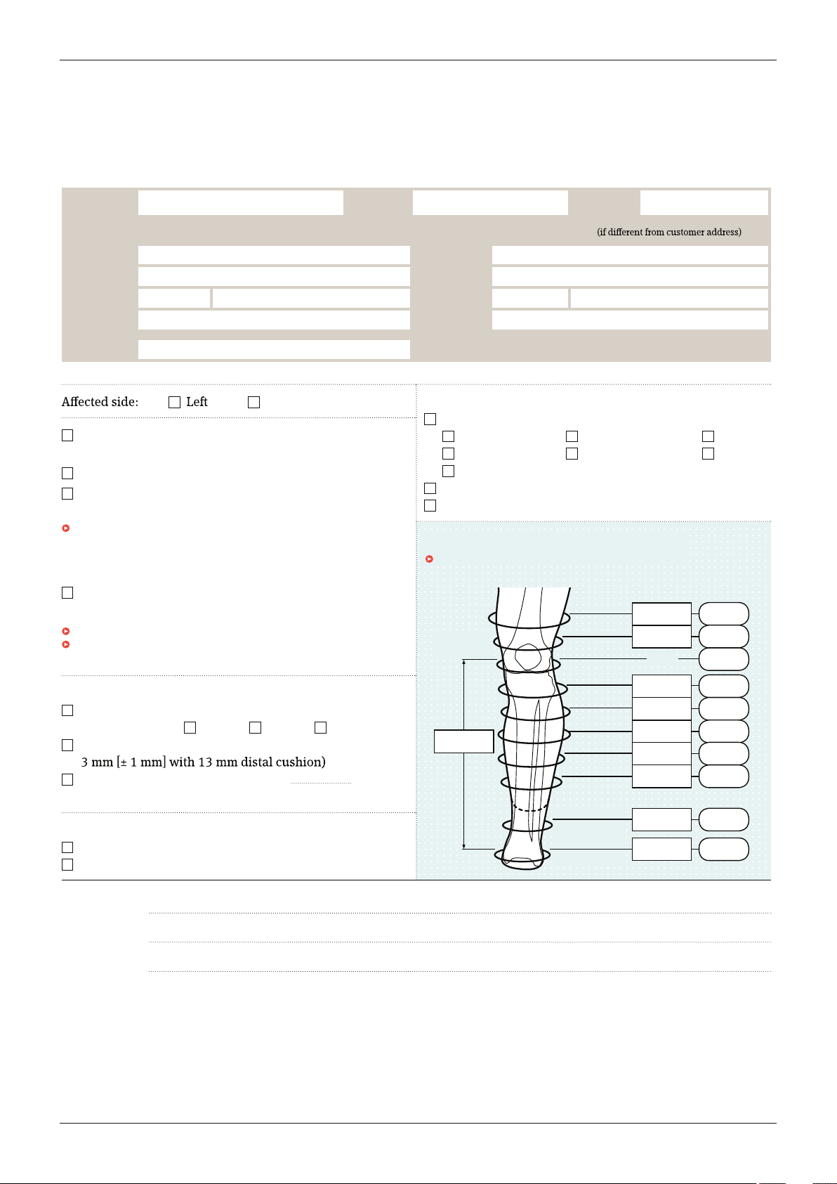
Measurement Form for Polyurethane (PUR) Liner
Transtibial and Syme amputations
Right
Exterior coating
gnitaoc elitxet htiW
1.6 mm, colour: Skin colour or Black
0.6 mm, colour: Skin colour or Black
1.0 mm, colour: Silver
Without textile coating (requires a non-adhesive coating)
YGOLONHCET DRAUGNIKS
6Y400 PUR custom liner from plaster cast and
measurement form
6Y400=M PUR custom liner from measurement form
6Y416 Shape Plus PUR custom liner from
plaster cast and measurement form
k sa hcus serutaef xelpmoc sah tsac retsalp eht fI nee flexion > 15°,
a bulging, eccentric or concave residual limb end, pronounced
invaginated scar tissue or excess size (length >
50 cm, circumference
>
50.5 cm), a 6Y416 Shape Plus Liner is required.
:renil motsuc tnemecalpeR
please contact customer service.
no elbissop era %01± fo secnarelot ssenkciht llaW subsequent orders.
of elif a sa atad tsac retsalp eht serots kcobottO r two years after the
most recent order.
Wall thickness
mrofinU (with 13 mm distal cushion)
(Wall thickness:
4 mm 5 mm 6 mm)
derepaT (6 mm wall thickness at knee centre tapering to
Width of the distal residual limb end mm
(if deviating from 13 mm)
Distal connector
tuohtiW
htiW (requires the selection of a textile coating)
Comments:
MPT
+ 100 mm
+ 50 mm
+ 50 mm
+ 100 mm
+ 150 mm
+ 200 mm
+ 250 mm
Minimum
circumference
mm
Maximum
circumference
mm
Residual
limb length
mm
Lower leg measurements
Extend the measurement sections if necessary.
Appendix
Ottobock | 31Harmony System
Page 32

Harmony System32 | Ottobock
Page 33

Ottobock | 33Harmony System
Page 34

Harmony System34 | Ottobock
Page 35

Kundenservice/Customer Service
Europe
OttoBock HealthCare DeutschlandGmbH
Max-Näder-Str. 15 · 37115 Duderstadt · Germany
T+495527848-3411 · F+495527848-1414
[email protected] · www.ottobock.de
Otto Bock Healthcare Products GmbH
Brehmstraße 16 · 1110 Wien · Austria
F +431 5267985
[email protected] · www.ottobock.at
Otto Bock Adria Sarajevo D.O.O.
Omladinskih radnih brigada 5
71000 Sarajevo · Bosnia-Herzegovina
T+38733766200 · F+38733766201
[email protected] · www.ottobockadria.com.ba
Otto Bock Bulgaria Ltd.
41 Tzar Boris III‘ Blvd. · 1612 Sofia · Bulgaria
T+35928057980 · F+35928057982
[email protected] · www.ottobock.bg
OttoBock Suisse AG
Luzerner Kantonsspital 10 · 6000 Luzern 16 · Suisse
T+41414556171 · F+41414556170
[email protected] · www.ottobock.ch
Otto Bock ČR s.r.o.
Protetická 460 · 33008 Zruč-Senec · Czech Republic
T+420377825044 · F+420377825036
[email protected] · www.ottobock.cz
OttoBock Iberica S.A.
C/Majada, 1 · 28760 Tres Cantos (Madrid) · Spain
T+34 918063000 · F+34 918060415
[email protected] · www.ottobock.es
Otto Bock France SNC
4 rue de la Réunion - CS 90011
91978 Courtaboeuf Cedex · France
T+33169188830 · F+33169071802
[email protected] · www.ottobock.fr
Otto Bock Healthcare plc
32, Parsonage Road · Englefield Green
Egham, Surrey TW20 0LD · United Kingdom
T +441784 744900 · F +441784 744901
[email protected] · www.ottobock.co.uk
OttoBock Hungária Kft.
Tatai út 74. · 1135 Budapest · Hungary
T+36 14511020 · F+36 14511021
[email protected] · www.ottobock.hu
Otto Bock Adria d.o.o.
Dr. Franje Tuđmana 14 ·10431 Sveta Nedelja · Croatia
T+38513361544 · F+38513365986
[email protected] · www.ottobock.hr
Otto Bock Italia Srl Us
Via Filippo Turati 5/7 · 40054 Budrio (BO) · Italy
T+39 051692-4711 · F+39 051692-4710
[email protected] · www.ottobock.it
Otto Bock Benelux B.V.
Mandenmaker 14 · 5253 RC
Nieuwkuijk · The Netherlands
T+31735186488 · F+31735114960
[email protected] · www.ottobock.nl
Industria Ortopédica Otto Bock Unip. Lda.
Av. Miguel Bombarda, 21 - 2º Esq.
1050-161 Lisboa · Portugal
T+351213535587 · F+351213535590
[email protected]
OttoBock Polska Sp. z o. o.
Ulica Koralowa 3 · 61-029 Poznań · Poland
T+48 616538250 · F+48 616538031
[email protected] · www.ottobock.pl
OttoBock Romania srl
Şos de Centura Chitila - Mogoşoia Nr. 3
077405 Chitila, Jud. Ilfov · Romania
T+40 214363110 · F+40 214363023
[email protected] · www.ottobock.ro
OOO Otto Bock Service
p/o Pultikovo, Business Park „Greenwood“,
Building 7, 69 km MKAD
143441 Moscow Region/Krasnogorskiy Rayon
Russian Federation
T+74955648360 · F+74955648363
[email protected] · www.ottobock.ru
OttoBock Scandinavia AB
Koppargatan 3 · Box 623 · 60114 Norrköping · Sweden
T+4611280600 · F+4611312005
[email protected] · www.ottobock.se
OttoBock Slovakia s.r.o.
Röntgenova 26 · 85101 Bratislava 5 · Slovak Republic
T+421232782070 · F+421232782089
[email protected] · www.ottobock.sk
OttoBock Sava d.o.o.
Industrijska bb · 34000 Kragujevac · Republika Srbija
T+38134351671 · F+38134351671
[email protected] · www.ottobock.rs
OttoBock Ortopedi ve
Rehabilitasyon Tekniği Ltd. Şti.
Ali Dursun Bey Caddesi · Lati Lokum Sokak
Meriç Sitesi B Block No: 6/1
34387 Mecidiyeköy-İstanbul · Turkey
T+90 2123565040 · F+90 2123566688
[email protected] · www.ottobock.com.tr
Africa
Otto Bock Algérie E.U.R.L.
32, rue Ahcène Outaleb - Coopérative les Mimosas
Mackle-Ben Aknoun · Alger · DZ Algérie
T+21321913863 · F+21321913863
[email protected] · www.ottobock.fr
Otto Bock Egypt S.A.E.
28 Soliman Abaza St. Mohandessein - Giza · Egypt
T+20233024390 · F+20233024380
[email protected] · www.ottobock.com.eg
Otto Bock South Africa (Pty) Ltd
Building 3 Thornhill Office Park · 94 Bekker Road
Midrand · Johannesburg · South Africa
T +27113121255
[email protected]
www.ottobock.co.za
Americas
Otto Bock Argentina S.A.
Av. Belgrano 1477 · CP 1093
Ciudad Autônoma de Buenos Aires · Argentina
T+54115032-8201 / 5032-8202
[email protected]
www.ottobock.com.ar
Otto Bock do Brasil Tecnica Ortopédica Ltda.
Alameda Maria Tereza, 4036, Bairro Dois Córregos
CEP: 13.278-181, Valinhos-São Paulo · Brasil
T +55 19 3729 3500 · F +55 19 3269 6061
[email protected] · www.ottobock.com.br
Otto Bock HealthCare Canada
5470 Harvester Road
Burlington, Ontario, L7L 5N5, Canada
T+1289288-4848 · F+1289288-4837
[email protected] · www.ottobock.ca
Otto Bock HealthCare Andina Ltda.
Calle 138 No 53-38 · Bogotá · Colombia
T+5718619988 · F+5718619977
[email protected] · www.ottobock.com.co
Otto Bock de Mexico S.A. de C.V.
Prolongación Calle 18 No. 178-A
Col. San Pedro de los Pinos
C.P. 01180 México, D.F. · Mexico
T+525555750290 · F+525555750234
[email protected] · www.ottobock.com.mx
Otto Bock HealthCare LP
11501 Alterra Parkway Suite 600
Austin, TX 78758 · USA
T+1 800 328 4058 · F+1 800 655 4963
[email protected]
www.ottobockus.com
Asia/Pacific
Otto Bock Australia Pty. Ltd.
Suite 1.01, Century Corporate Centre
62 Norwest Boulevarde
Baulkham Hills NSW 2153 · Australia
T+61288182800 · F+61288144500
[email protected] · www.ottobock.com.au
Beijing Otto Bock Orthopaedic Industries Co., Ltd.
B12E, Universal Business Park
10 Jiuxianqiao Road, Chao Yang District
Beijing, 100015, P.R. China
T+861085986880 · F+861085980040
[email protected]
www.ottobock.com.cn
Otto Bock Asia Pacific Ltd.
Unit 1004, 10/F, Greenfield Tower, Concordia Plaza
1 Science Museum Road, Tsim Sha Tsui
Kowloon, Hong Kong · China
T +852 2598 9772 · F +852 2598 7886
[email protected] · www.ottobock.com
Otto Bock HealthCare India Pvt. Ltd.
20th Floor, Express Towers
Nariman Point, Mumbai 400 021 · India
T +91 22 2274 5500 / 5501 / 5502
[email protected] · www.ottobock.in
OttoBock Japan K. K.
Yokogawa Building 8F, 4-4-44 Shibaura
Minato-ku, Tokyo, 108-0023 · Japan
T+8133798-2111 · F+8133798-2112
[email protected] · www.ottobock.co.jp
OttoBock Korea HealthCare Inc.
4F Agaworld Building · 1357-74, Seocho-dong
Seocho-ku, 137-070 Seoul · Korea
T+822577-3831 · F+822577-3828
[email protected] · www.ottobockkorea.com
OttoBock South East Asia Co., Ltd.
1741 Phaholyothin Road
Kwaeng Chatuchark · Khet Chatuchark
Bangkok 10900 · Thailand
T+6629303030 · F+6629303311
[email protected] · www.ottobock.co.th
Page 36

Printed by:
Otto Bock HealthCare GmbH
Max-Näder-Straße 15 · 37115 Duderstadt · Germany
T +49 5527 848-0 · F +49 5527 72330
[email protected] · www.ottobock.com
Ottobock has a certified Quality Management System in accordance with ISO 13485.
© Ottobock · 646T2=1.8GB-06-1511
 Loading...