

Page 1
B500 classic/advanced
Instructions for Use (User)
Page 2
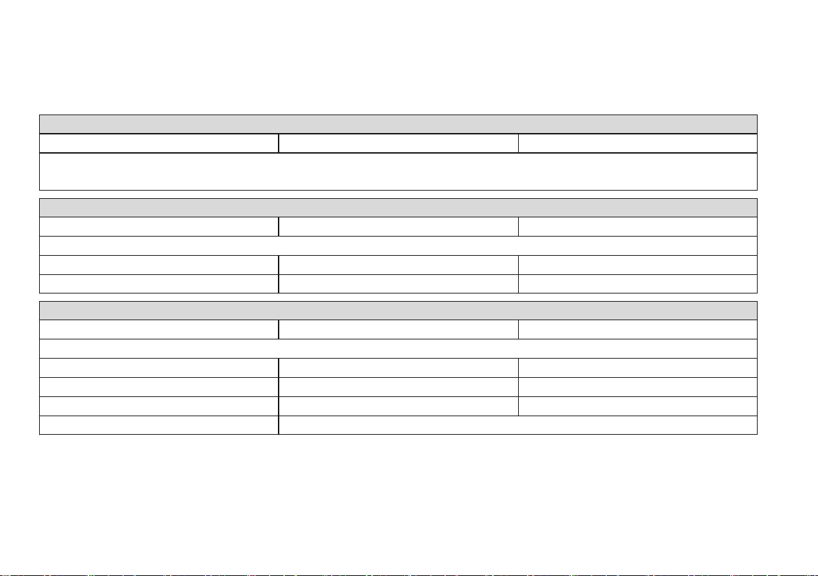
Additional options for the B500 advanced
The model B500 advanced power wheelchair can be equipped with the following additional options (applicable options are
checked):
Electronic drive-away lock*
[ ] Function enabled [ ] Function disabled
If enabled, the function is activated by pressing the mode button on the control panel.
The function is deactivated with the joystick.
Electronic steering lock*
[ ] Function enabled [ ] Function disabled
The electronic steering lock is turned on or off with the following button when the motors are at standstill:
[ ] Warning flasher [ ] Direction indicator, right [ ] Direction indicator, left
[ ] Horn [ ] Light [ ] Mode
2-way adapter cable*
[ ] Adapter cable included [ ] Adapter cable not included
The included adapter cable allows the following functions to be selected directly through separate buttons:
[ ] Footrest, left [ ] Footrest, right [ ] Seat tilt
[ ] Seat height adjustment [ ] Back angle adjustment [ ] Light
[ ] Direction indicator, right [ ] Direction indicator, left [ ] Horn
[ ] Warning flasher [ ] Other:
*See the section 'Usage' for more information.
Page 3

Table of contents
Table of contents
Foreword 1 6...............................................................
Product Description2 7.............................................
Function 2.1 7..........................................................
Product Overview2.2 7..............................................
Safety3 8.....................................................................
Explanation of Warning Symbols3.1 8.........................
General Safety Instructions3.2 8................................
Reference to additional safety instructions3.3 9............
Name plate and warning labels3.4 10.........................
Name plate3.4.1 10.....................................................
Warning labels3.4.2 11................................................
Delivery4 12................................................................
Scope of supply4.1 12..............................................
Options4.2 12..........................................................
Model B500 classic4.2.1 12.........................................
Model B500 advanced4.2.2 12.....................................
Storage4.3 12..........................................................
During daily use4.3.1 12..............................................
In case of extended disuse4.3.2 12...............................
Preparation for Use5 13............................................
Safety Instructions5.1 13...........................................
Initial operation5.2 14...............................................
Locking the back angle adjustment in place5.2.1 14........
Adjustments5.3 15....................................................
Prerequisites5.3.1 15..................................................
Adjusting the back angle5.3.2 15..................................
Adjusting the side panels5.3.3 16..................................
Adjusting the footrests5.3.4 17.....................................
Adjusting the belt lengths5.3.5 18.................................
Adjusting the control panel5.3.6 18...............................
Changing control unit parameters5.3.7 19......................
Usage6 19...................................................................
Side panels6.1 19....................................................
Footrests6.2 20........................................................
Getting in / transfer6.3 21..........................................
Control unit6.4 23....................................................
Control Panel6.4.1 23..................................................
Buttons and display functions6.4.2 24...........................
Driving Functions6.5 26............................................
Safety Instructions6.5.1 26...........................................
Driving notes6.5.2 28..................................................
Switching on and off6.5.3 29........................................
Selecting the speed levels6.5.4 30................................
Driving6.5.5 30...........................................................
Ottobock | 3B500 classic/advanced
Page 4

Table of contents
Range6.5.6 31............................................................
Drive-away lock6.5.7 32...............................................
Steering lock6.5.8 33..................................................
Adjusting the driving characteristics6.5.9 34...................
Activating/deactivating the brakes6.6 34......................
Batteries/charging process6.7 36...............................
Safety Instructions6.7.1 36...........................................
General6.7.2 36..........................................................
Battery charging information6.7.3 36.............................
Battery charger6.7.4 37...............................................
Charging the battery6.7.5 38........................................
Power seat functions6.8 39........................................
Safety Instructions6.8.1 39...........................................
Power seat height adjustment6.8.2 41...........................
Power seat tilt6.8.3 42.................................................
Power back angle adjustment6.8.4 43...........................
Power footrests6.8.5 44...............................................
Controlling power seat functions6.8.6 45.......................
Joystick and display functions6.8.7 46...........................
Manual seat functions6.9 47......................................
Safety Instructions6.9.1 47...........................................
Manual seat tilt6.9.2 47................................................
Manual back angle adjustment6.9.3 47..........................
Manual elevating footrests6.9.4 48................................
Additional seat options6.10 48.....................................
Contour seat6.10.1 48...................................................
6.13.3
Recaro® seat6.10.2 49...................................................
Headrest6.10.3 51........................................................
Control unit accessories6.11 52...................................
Attendant control6.11.1 52.............................................
Push-button module6.11.2 55.........................................
Adapter cable for Piko button6.11.3 57............................
External odometer6.11.4 57............................................
Additional options6.12 57............................................
Control panel holder6.12.1 57........................................
Lights6.12.2 58............................................................
Belts / belt systems6.12.3 59..........................................
Suspension (steering casters/drive wheels)6.12.4 61........
Locking the steering casters6.12.5 62.............................
Rear bumper6.12.6 62...................................................
Overview of additional options6.12.7 63..........................
Disassembly/transport6.13 63.....................................
Safety Instructions6.13.1 63...........................................
Reducing the transportation size6.13.2 64.......................
Reducing the transportation size – Recaro®
seat
Preparing for transport6.13.4 65.....................................
Use in a wheelchair accessible vehicle6.14 66...............
Safety Instructions6.14.1 66...........................................
Permitted use6.14.2 66..................................................
Restrictions for Use6.14.3 67.........................................
Necessary accessories6.14.4 67....................................
65...............................................................
4 | Ottobock B500 classic/advanced
Page 5

Table of contents
Use6.14.5 67................................................................
Care6.15 67..............................................................
Safety Instructions6.15.1 67...........................................
Cleaning6.15.2 68........................................................
Disinfection6.15.3 68....................................................
Maintenance/Repair7 68..........................................
Safety Instructions7.1 68...........................................
Maintenance7.2 69...................................................
Maintenance intervals7.2.1 70......................................
Repair7.3 72............................................................
Replacing a defective fuse7.3.1 72................................
Replacing a defective bulb7.3.2 74................................
Replacing the battery7.3.3 75.......................................
Troubleshooting7.4 75..............................................
Types of notifications7.4.1 76.......................................
Wheelchair control unit fault overview7.4.2 77................
Attendant control fault overview7.4.3 79.........................
Disposal8 80...............................................................
Safety Instructions8.1 80...........................................
Disposal Information8.2 80........................................
Legal Information9 80...............................................
Service life9.1 80......................................................
Liability9.2 80..........................................................
CE Conformity9.3 80................................................
Warranty terms9.4 81...............................................
Trademarks9.5 81....................................................
Appendices10 82..........................................................
Technical data10.1 82.................................................
Ottobock | 5B500 classic/advanced
Page 6

Foreword
1 Foreword
INFORMATION
Date of the last update: 2013-08-16
► Please read this document carefully.
► Follow the safety instructions.
INFORMATION
► These instructions for use (user) can be viewed and
downloaded from the homepage www.ottobock.com. It
is possible to increase the display size of the PDF doc
ument stored there.
► Please note that the instructions for use are revised
regularly. The latest version can be viewed and down
loaded on the respective product page at
www.ottobock.com.
► For further questions about the instructions for use
(user), please contact the qualified personnel who
issued the product to you.
With this wheelchair, you have purchased a high quality
product which can be put to versatile, daily use at home and
outdoors.
Be sure to read these instructions for use before you start
using the wheelchair. In particular, please observe the
information in the chapters "Safety" and "Use".
Please note the following:
• If you have any questions or cannot solve a problem
despite reading these instructions for use, please con
tact the qualified personnel who fitted the product or the
manufacturer's service department (please see inside
back cover or back cover for addresses).
• All users and/or attendants must be instructed by the
qualified personnel in the use of the product with the aid
of these instructions for use. In particular, users and/or
attendants must be informed of the residual risk with the
aid of the safety instructions in these instructions for
use.
• The product has been adapted to the needs of the user.
Further changes may be made only by qualified person
nel. The manufacturer recommends checking the set
tings regularly in order to assure an optimum fit over the
long term. Especially for children and youth, they should
be checked every six months.
• The product may be combined only with the options lis
ted here. The manufacturer assumes no liability for com
binations with third-party medical devices and/or
accessories not included in the modular system.
• Please note also the information in the chapter "Liabil
ity".
6 | Ottobock B500 classic/advanced
Page 7
Product Description
• The operational safety of the wheelchair can only be
ensured if it is used properly in accordance with the
information contained in these instructions for use. The
user is ultimately responsible for accident-free opera
tion.
• Your wheelchair model may differ from the models
shown. In particular, not all the options described in
these instructions for use will be installed on your wheel
chair.
• We reserve the right to make technical changes to the
model described in these instructions for use.
2 Product Description
2.1 Function
The wheelchair is designed solely for individual use by per
sons who are unable to walk or who have a walking impedi
ment, and can be operated either by the patient or by anoth
er person.
The wheelchair can be used on solid ground both indoors
and outdoors.
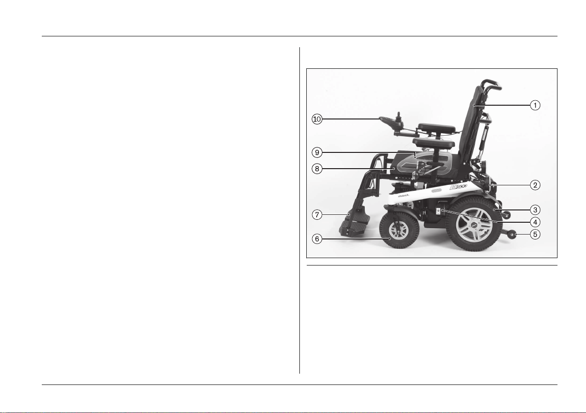
2.2 Product Overview
Fig. 1 Main components
1 Backrest 6 Caster wheel
2 Rear LED lights 7 Footplates
3 Drive wheel 8 Seat cushion
4 Motor with brake release 9 Side panel (here: with front
lights)
5 Anti-tipper 10 Control panel
Ottobock | 7B500 classic/advanced
Page 8
Safety
3 Safety
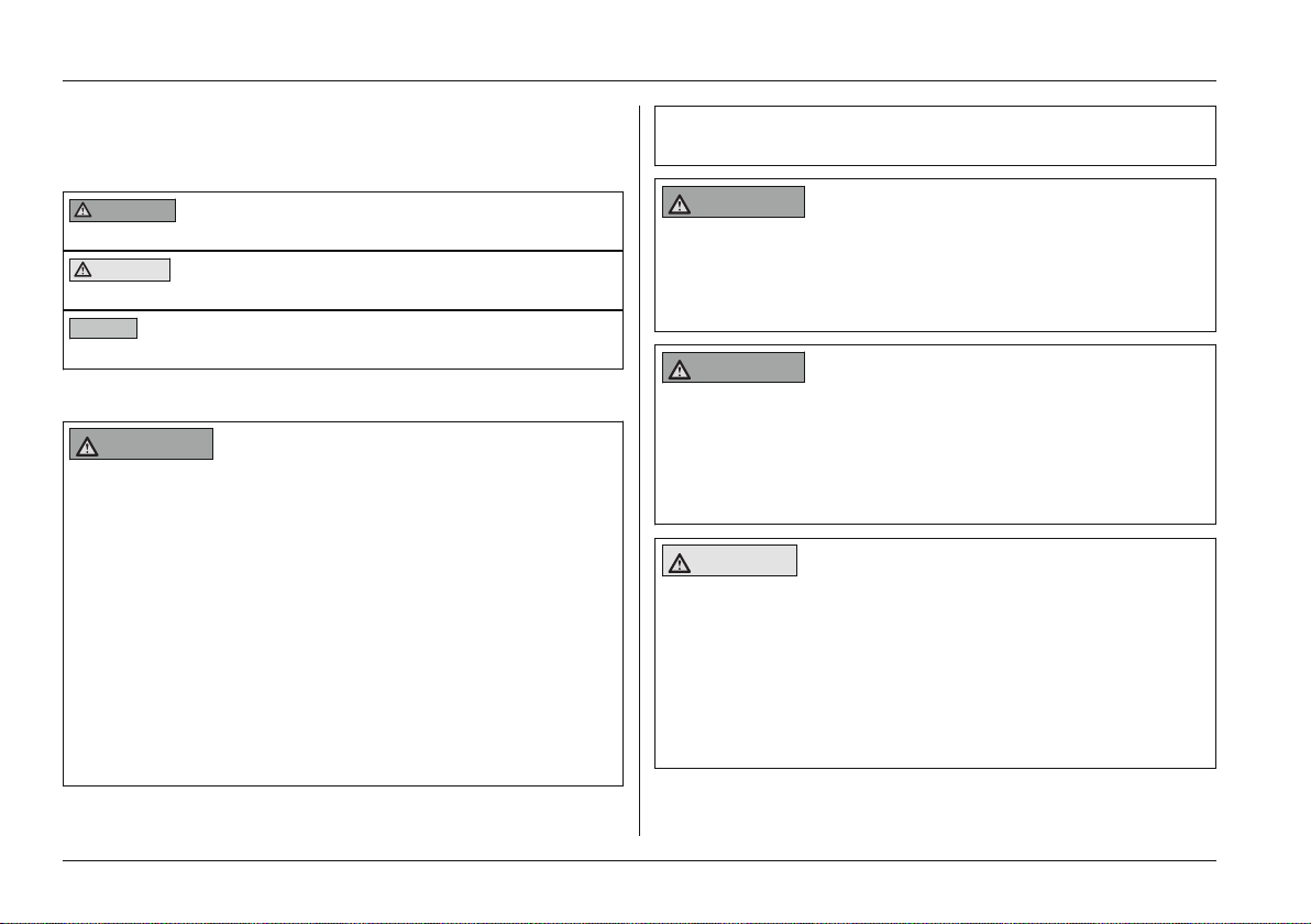
3.1 Explanation of Warning Symbols
WARNING
CAUTION
NOTICE
3.2 General Safety Instructions
WARNING
Improper product operation
Falling, tipping over, collision due to user error
► The product may only be used by a qualified user.
► As a user or attendant, you must be trained in the use
of the product by qualified personnel instructed by the
manufacturer.
► Read the entire instructions for use.
► The product may not be used in case of exhaustion or
under the influence of alcohol or medications.
► The product may not be used in road traffic by users
who have any mental limitations which can temporarily
or permanently limit attentiveness and judgement.
Warnings regarding possible risks of severe
accident or injury.
Warnings regarding possible risks of acci
dent or injury.
Warnings regarding possible technical dam
age.
► You must observe road traffic regulations when driving
in road traffic.
WARNING
Failure to heed or observe the safety instructions
Risk of pinching, crushing, being pulled in, tipping, falling
► Observe all safety instructions in these instructions for
use and in all other applicable documents.
WARNING
Improper use of the product
Risk of pinching, crushing, being pulled in, tipping, falling
► Only use this product for its original intended purpose.
► Only one person may be transported with the product
at any one time.
CAUTION
Seat cushion or backrest cover may ignite
User may sustain burns
► The seat cushion and backrest cover are not highly
flammable, but there is a possibility they may catch fire.
Therefore utmost caution is required near open flame.
► Keep away from any sources of fire, especially burning
cigarettes.
8 | Ottobock B500 classic/advanced
Page 9

Safety
CAUTION
Extreme temperatures
Risk of hypothermia or burns on components, failure of
components
► Do not expose the product to any extreme temperat
ures (e.g. direct sunlight, sauna, extreme cold).
NOTICE
Overloading
Damage to the product
► Do not exceed the maximum load capacity (see the
section "Technical Data").
NOTICE
Use under incorrect environmental conditions
Damage to the product
► Only use the product within a temperature range of -25
°C to +50 °C.
3.3 Reference to additional safety instructions
Observe additional safety instructions in the following
chapters:
• Chapter "Preparation for Use"
• Chapter "Usage" > "Driving Functions"
• Chapter "Usage" > "Batteries/Charging Process"
• Chapter "Usage" > "Power Seat Functions"
• Chapter "Usage" > "Manual Seat Functions"
• Chapter "Usage" > "Disassembly/Transport"
• Chapter "Usage" > "Use in a Wheelchair Accessible
Vehicle"
• Chapter "Usage" > "Care"
• Chapter "Maintenance/Repair"
• Chapter "Disposal"
Ottobock | 9B500 classic/advanced
Page 10
Safety
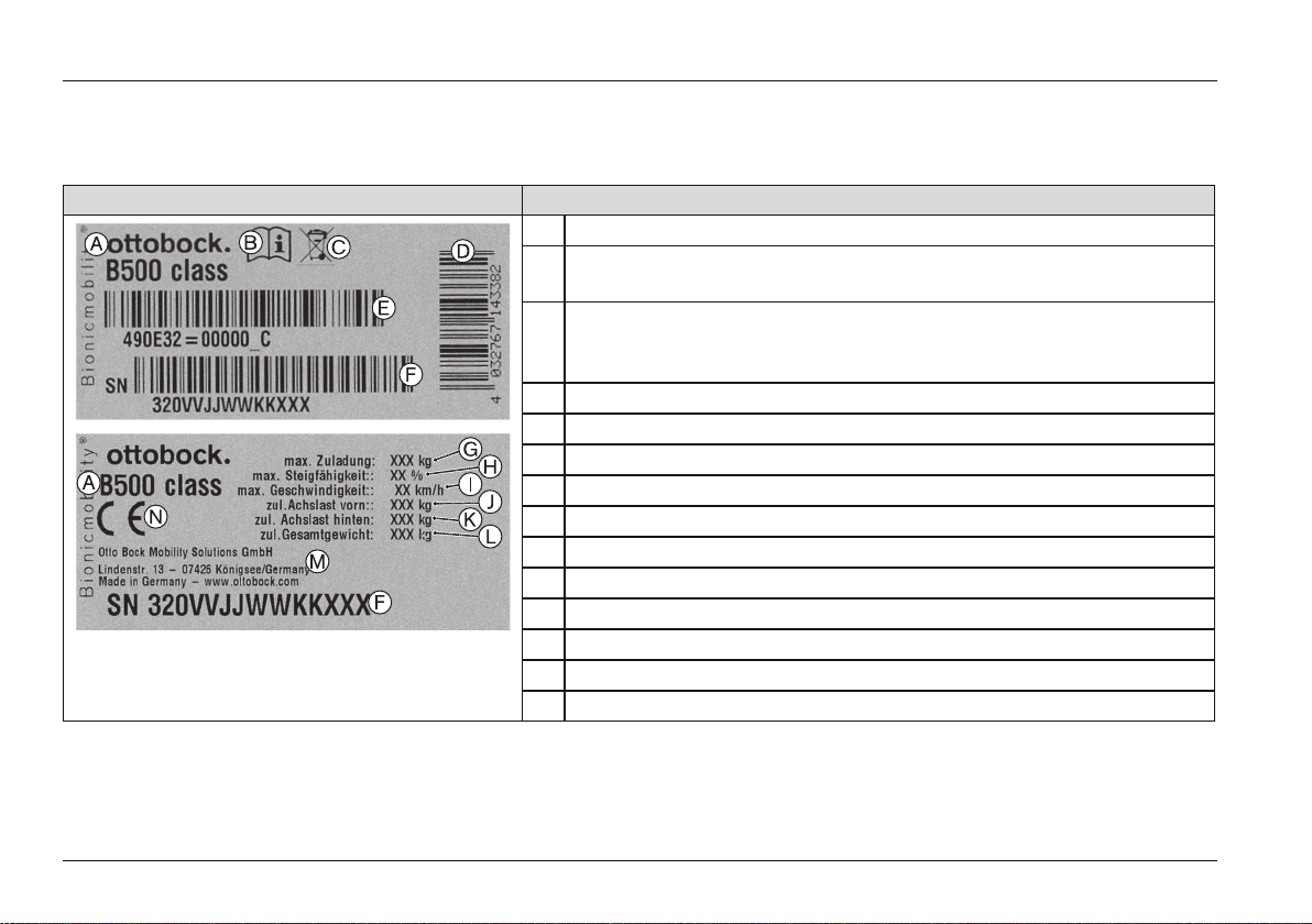
3.4 Name plate and warning labels
3.4.1 Name plate
Label Meaning
The name plate is located on the side of the
frame below the seat.
A Type designation
B Read the instructions for use before using the product. Observe
safety information in the instructions for use.
C Symbol for separate collection of electric and electronic devices.
Components of the power wheelchair and batteries may not be dis
posed of in household waste.
D European article number (EAN)
E Product reference number
F Serial number (including year of manufacture)
G Maximum load capacity (see chapter "Technical Data")
H Maximum climbing ability (see chapter "Technical Data")
I Maximum speed (see chapter "Technical Data")
J Allowable axle load, front
K Allowable axle load, rear
L Maximum gross weight
M Manufacturer information/address
N CE marking – product safety according to EU guidelines
10 | Ottobock B500 classic/advanced
Page 11
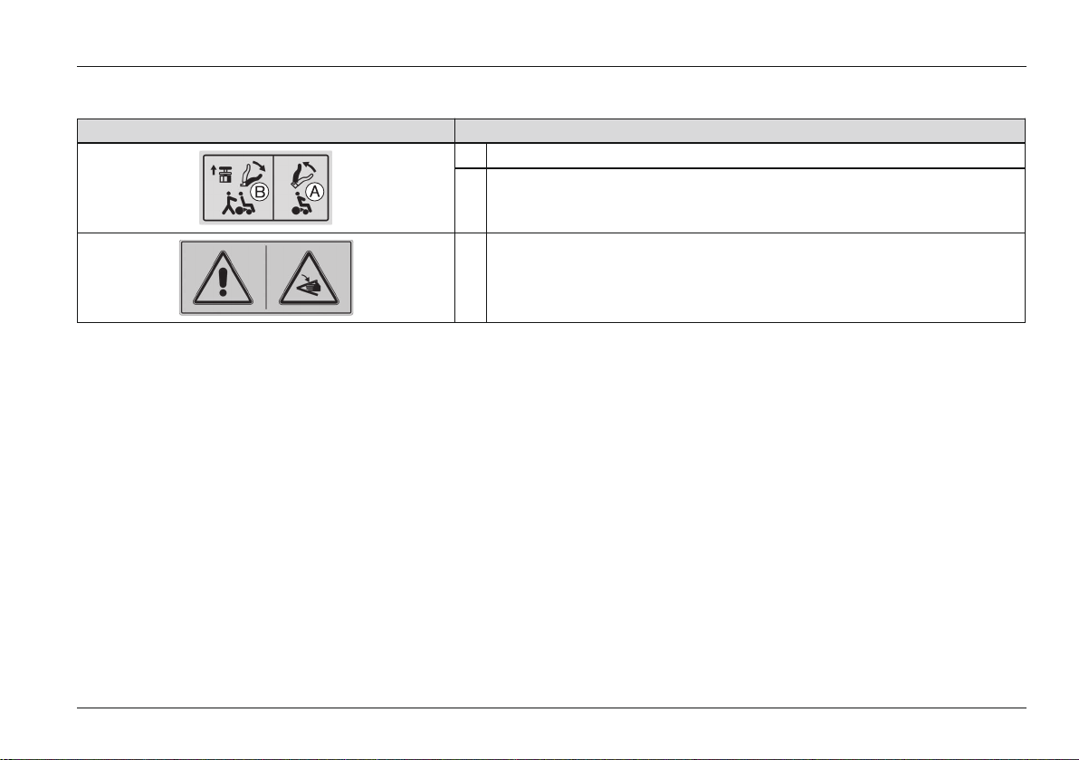
3.4.2 Warning labels
Safety
Label Meaning
A Electric driving mode: lock motor brake
B Manual driving mode: unlock motor brake
Risk of pinching. Do not reach into the danger area.
Ottobock | 11B500 classic/advanced
Page 12

Delivery
4 Delivery
4.1 Scope of supply
The power wheelchair is normally shipped fully assembled
and fitted to the personal requirements of the respective
user.
The scope of delivery includes:
• Fitted power wheelchair with main components
• Installed options
• Battery charger
• Instructions for Use (user)
4.2 Options
The standard model can be fitted to the user's personal
requirements through a large range of options.
A full list of the available modules and accessories is shown
on the order form and in the accessories catalogue.
To use options: see Page19 et. seq.
4.2.1 Model B500 classic
The B500 classic power wheelchair can be equipped with
up to 2 of the following power seat options:
• Power seat height adjustment
• Power seat tilt available in 3 different versions (up to
20°, up to 30°, up to 45°)
• Power back angle adjustment up to 30°
• Power adjustable footrests
The wheelchair is controlled by an enAble40 control unit.
4.2.2 Model B500 advanced
The B500 advanced power wheelchair can be equipped
with up to 4 of the following power seat options:
• Power seat height adjustment
• Power seat tilt available in 2 different versions (up to
30°, up to 45°)
• Power back angle adjustment up to 30°
• Power adjustable footrests with 3 programmable ver
sions (control of only left, only right or both sides)
The wheelchair is controlled by an enAble50 control unit.
For additional information on enabling/user specific adjust
ment of certain enAble50 control unit functions: see inside
front cover.
4.3 Storage
4.3.1 During daily use
The power wheelchair should always be protected against
external influences.
The control unit must be turned off.
4.3.2 In case of extended disuse
NOTICE
Deep discharge due to standby current
Risk of battery damage
12 | Ottobock B500 classic/advanced
Page 13
Preparation for Use
► Remove the fuse if the wheelchair is not used for more
than 3 days.
INFORMATION
To remove the fuse, see section "Repair" > "Replacing a
defective fuse".
Please observe the following if the power wheelchair is not
used for more than 3days:
Storage conditions
• Maintain an ambient temperature between -40°C and
+65°C and a relative humidity between 45% and 85%.
• Store the power wheelchair in a dry, enclosed room with
sufficient air circulation and protection from external
influences.
• Protect the wheels against ground frost, e.g., by reliev
ing them completely through assembly blocks or
wooden boards.
• Fill the wheels with slight overpressure and rotate them
at regular weekly intervals to prevent flat tyres from
extended standing.
Note regarding the tyres
• If the power wheelchair is not moved for several days,
permanent colour changes may occur where the wheel
chair comes into contact with the surface it is standing
on. Therefore a suitable underlay should be used if the
product is parked for extended periods of time.
• Tyres contain chemical substances that can react with
other chemical substances (such as cleaning agents,
acids, etc.).
• Black tyres contain soot particles. They may leave black
marks where they come into contact with the ground.
Therefore the manufacturer recommends grey tyres if
the wheelchair is primarily used indoors.
• Avoid unnecessary parking outdoors. Direct exposure to
sunlight/UV radiation causes the tyres to age more
quickly. As a result, the tread surface hardens and
corner pieces break out of the tread.
• The tyres must be changed when the tread is less than 1
mm to ensure safe driving behaviour.
• The tyres should be replaced every 2 years regardless
of wear and tear.
5 Preparation for Use
5.1 Safety Instructions
WARNING
Improper modification of the settings
Risk of tipping, falling, improper user posture
► Do not modify the settings established by the qualified
personnel.
► In case of problems with the settings (control panel
problems etc.), please contact the qualified personnel
who fitted your product.
Ottobock | 13B500 classic/advanced
Page 14
Preparation for Use
WARNING
Improper handling of packaging materials
Risk of suffocation
► Keep packaging materials away from children.
CAUTION
Uncontrolled movement of components when making
adjustments
Risk of crushing, pinching, blows to limbs
► Ensure that body parts, such as hands or head, are
never in the danger zone.
► Perform the work with the aid of a helper for support.
CAUTION
Unsecured screw connections
Risk of pinching, crushing, tipping over, falling of user
► After all adjusting/readjusting work, retighten the
mounting screws/nuts firmly. Observe any torque set
tings which may be specified.
► Any time you loosen a screw connection with thread
lock, replace it with a new screw connection or secure
the old screw connection with medium strength thread
locker (e.g. Loctite 241®).
5.2 Initial operation
The specialist dealer ships the power wheelchair fully
assembled and ready to use.
The following additional tasks may be required:
• Adjusting settings: see Page15 et. seq.
• Installing the side panels: see Page19
• Installing the footrests: see Page20
• Charging the battery: see Page36 et. seq.
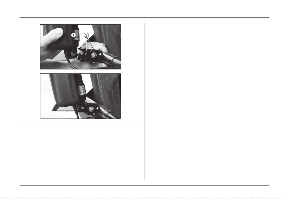
5.2.1 Locking the back angle adjustment in place
If the power wheelchair is equipped with mechanical/power
back angle adjustment, proceed as follows if necessary:
1) Fold the backrest up.
2) Place the cross bolt on the end of the gas compression
spring or actuator into the bracket (see Fig.2, item 1).
3) Push the lever down until the lock engages (see Fig.2,
item 2).
4) Check the bolt and lock to ensure that they are securely
engaged.
14 | Ottobock B500 classic/advanced
Page 15
Preparation for Use
5.3 Adjustments
5.3.1 Prerequisites
Fine fitting/adjusting work should always be performed with
the user. The user should sit upright in the power wheel
chair while adjustments are made.
Seat height, seat width and seat angle are set according to
the customer order and may only be changed by a specialist
dealer.
The following can be adjusted by the user:
• Back angle
• Armrest height and position
• Lower leg length
• Strap lengths
• Position of the control panel
All parts of the product should be cleaned thoroughly before
adjustments are made.
Fig. 2 Place the cross bolt into the bracket (top); locked
cross bolt (bottom)
1 Cross bolt 2 Lock with lever
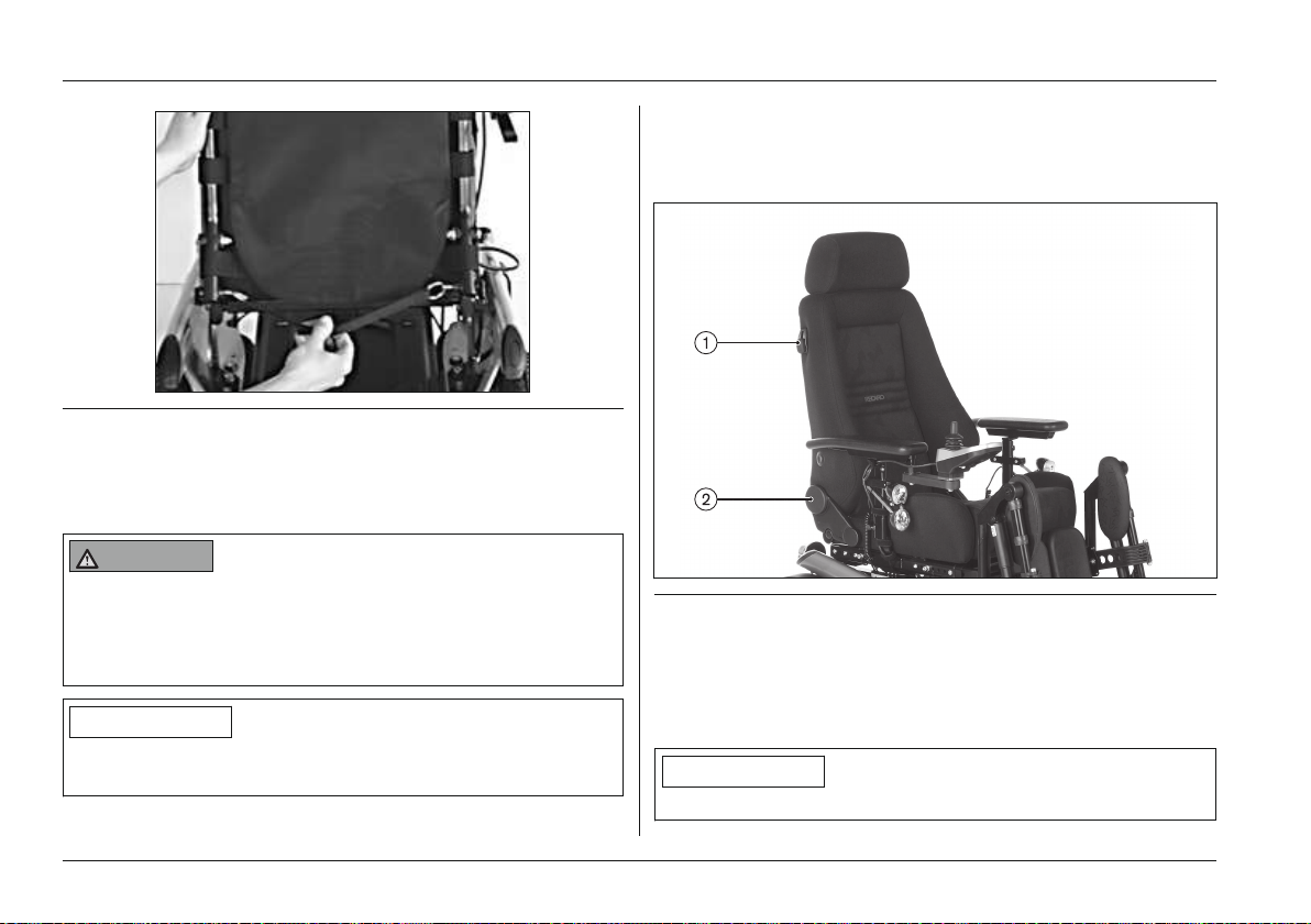
5.3.2 Adjusting the back angle
Standard/contour seat
1) Pull on the strap until the locking bolts are free.
2) Change the backrest angle to the desired position.
3) Release the strap. The locking bolts engage at the
desired position.
Ottobock | 15B500 classic/advanced
Page 16
Preparation for Use
Fig. 3 Adjusting the back angle
1 Release/locking strap 2 Locking bolts
Recaro® seat
WARNING
Incorrect Recaro® Seat settings
Risk of falling, tipping
► Note that the maximum backrest angle is 30° while
standing and 20° while driving.
► Turn the knob on the left or right side of the backrest
until the backrest is in the desired position (see Fig.4,
item 2).
Fig. 4 Adjusting the Recaro® seat angle
1 Release handle
2 Back angle adjustment knob
INFORMATION
5.3.3 Adjusting the side panels
For further Recaro® seat settings: see the chapter
"Recaro® seat".
INFORMATION
To remove and install the side panels: see Page19.
16 | Ottobock B500 classic/advanced
Page 17
Preparation for Use
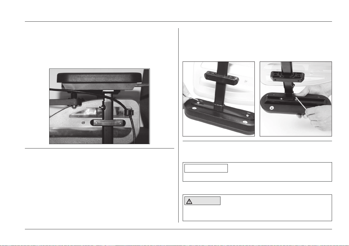
Adjusting the armrest height
1) Loosen the Allen head screw on the side panel with a
size 3 Allen key (see Fig.5).
2) Slide the armrests up or down to the desired position.
3) Tighten the Allen head screw.
Fig. 5 Allen head screw for height adjustment
Adjusting the armrest to the forearm length
1) Depending on the version, loosen 2 x Allen head screws
on the bottom of the armrest (see Fig.6).
2) Adjusting the armrest:
→ Version 1:Push the armrest along the slotted holes
to the front or back into the desired position ((see
Fig.6), left).
→ Version 2: Slide the armrest with the spare tube for
ward or backwards along the attachment rail to the
desired position ((see Fig.6), right).
3) Tighten the 2 Allen head screws.
Fig. 6 Adjusting the armrest depth
5.3.4 Adjusting the footrests
INFORMATION
To remove and install the footrests: see Page20.
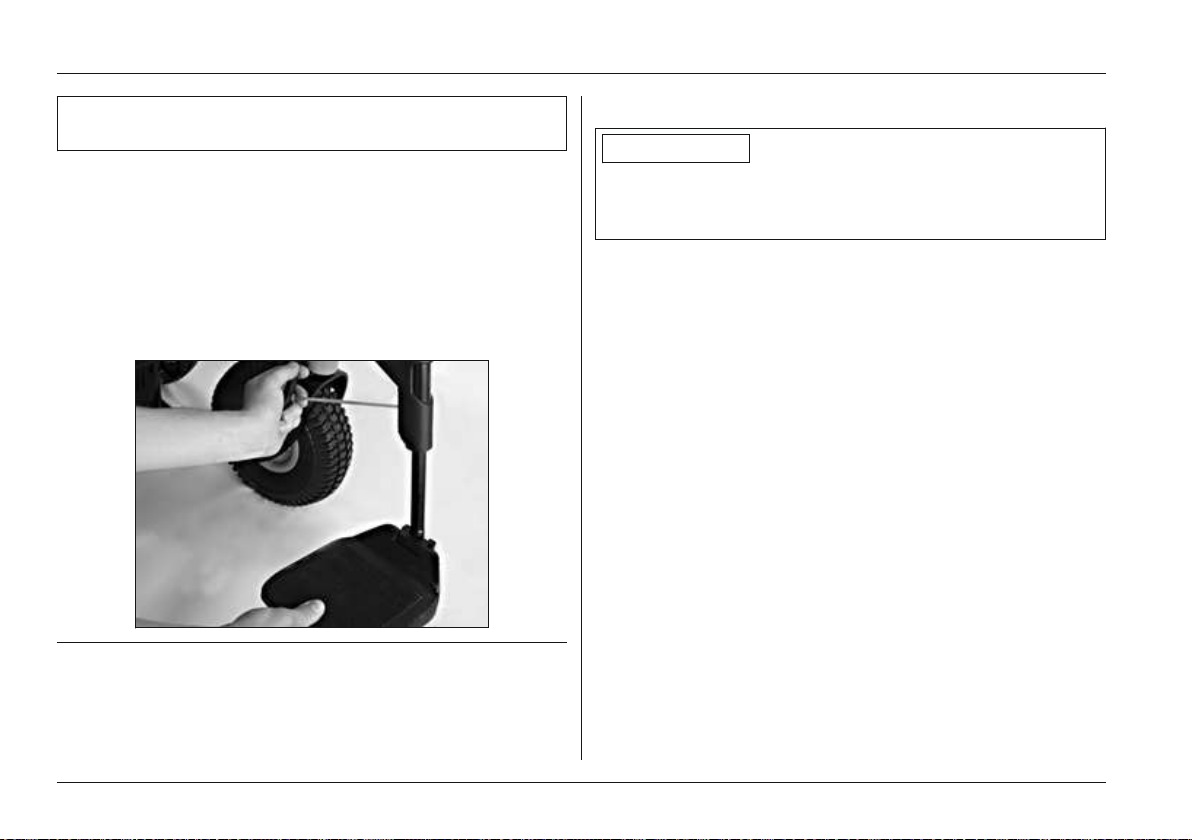
Adjusting the lower leg length
CAUTION
Exposed pinch points
Pinching, crushing of fingers
Ottobock | 17B500 classic/advanced
Page 18
Preparation for Use
► Ensure that your fingers are not in the danger area
when flipping the footrests up or down.
1) Loosen the grub screws or Allen head screws (depend
ing on the version) on the footplate bar (see Fig.7).
2) Adjust the footplate bar to match the user's lower leg
length.
INFORMATION: Ensure that the footplate bar is
inserted into the swivel segment by at least 40mm.
3) Tighten the grub screws or Allen head screws (depend
ing on the version) on the footplate bar.
Fig. 7 Adjusting the lower leg length (standard footrest)
5.3.6 Adjusting the control panel
INFORMATION
The power wheelchair may be equipped with an optional
height-adjustable or swing-away control panel holder (see
Page57).
Adjusting the control panel to the forearm length
1) Loosen the 3 set screws on the bottom of the armrest.
2) Slide the rail with the control panel forwards or back
wards.
INFORMATION: If the control panel rail is too long
it can be shortened. Please contact the qualified
personnel who adjusted your product.
3) Tighten the 3 set screws on the bottom of the armrest.
5.3.5 Adjusting the belt lengths
To adjust the belt lengths: see Page59.
18 | Ottobock B500 classic/advanced
Page 19
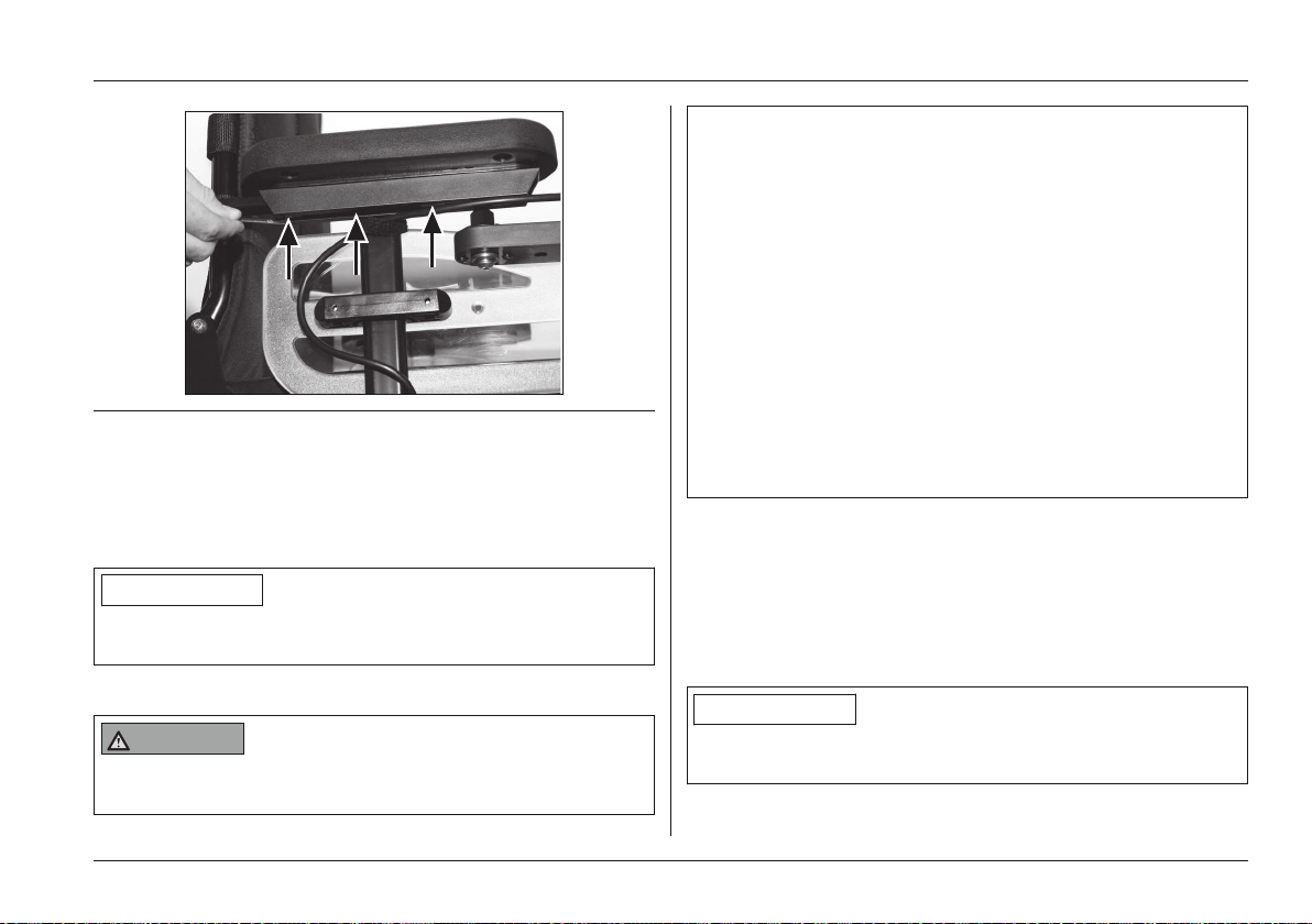
Fig. 8 Adjusting the control panel
Changing the control panel side
By default, the control panel is mounted on the side spe
cified in the order. It can also be mounted on the other side
later on if the user so desires.
INFORMATION
The control panel mounting side may only be changed by
authorised personnel.
5.3.7 Changing control unit parameters
WARNING
Incorrect configuration settings
Falling, tipping over, collision due to programming errors
Usage
► Programming may only be performed by qualified per
sonnel trained by the manufacturer. The manufacturer
of the product and the control unit manufacturer are
not liable in case of damage caused by programming
which was not performed properly and/or which was
not adjusted properly according to the user's abilities.
► Note that modified parameter settings in the configura
tion can lead to changes in driving characteristics. In
particular, changes to the speed, acceleration, braking
or joystick settings can lead to unexpected and there
fore uncontrollable driving characteristics and cause
an accident.
► After configuration/programming is complete, the user
must test the driving characteristics of the product
under the supervision of the qualified personnel.
If necessary, the qualified personnel can fit the already pre
programmed wheelchair control system and accessories to
the specific user requirements.
6 Usage
6.1 Side panels
INFORMATION
For additional information on side panels with lighting: see
Page58.
Ottobock | 19B500 classic/advanced
Page 20
Usage
Removing the side panel
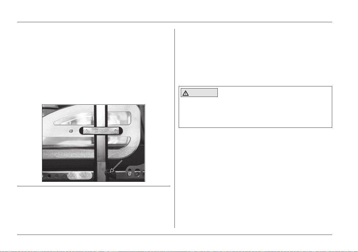
1) Loosen the wing screw on the side panel holder (see
Fig.9).
2) Pull the side panel out from the side panel holder and
set it aside.
3) Only for a side panel with a control panel: carefully let
the side panel with the control panel hang down.
INFORMATION: If necessary, the hook-and-loop
closures for routing the control panel cable can be
undone and the control panel can be removed.
Fig. 9 Side panel wing screw
Installing the side panel
1) If necessary, install the control panel and fasten the
hook-and-loop closures for routing the control panel
cable.
2) Insert the side panel into the side panel holder.
3) Re-tighten the wing screw on the side panel holder.
6.2 Footrests
CAUTION
Exposed pinch points
Pinching, crushing of fingers
► Ensure that your fingers are not in the danger area
when flipping the footrests up or down.
Removing the footrests
1) Unhook the calf band.
2) Flip the footplate up.
3) Release the footrest lock (see Fig.10).
4) Flip the footrest out or in.
5) Pull the footrest up and remove it.
20 | Ottobock B500 classic/advanced
Page 21
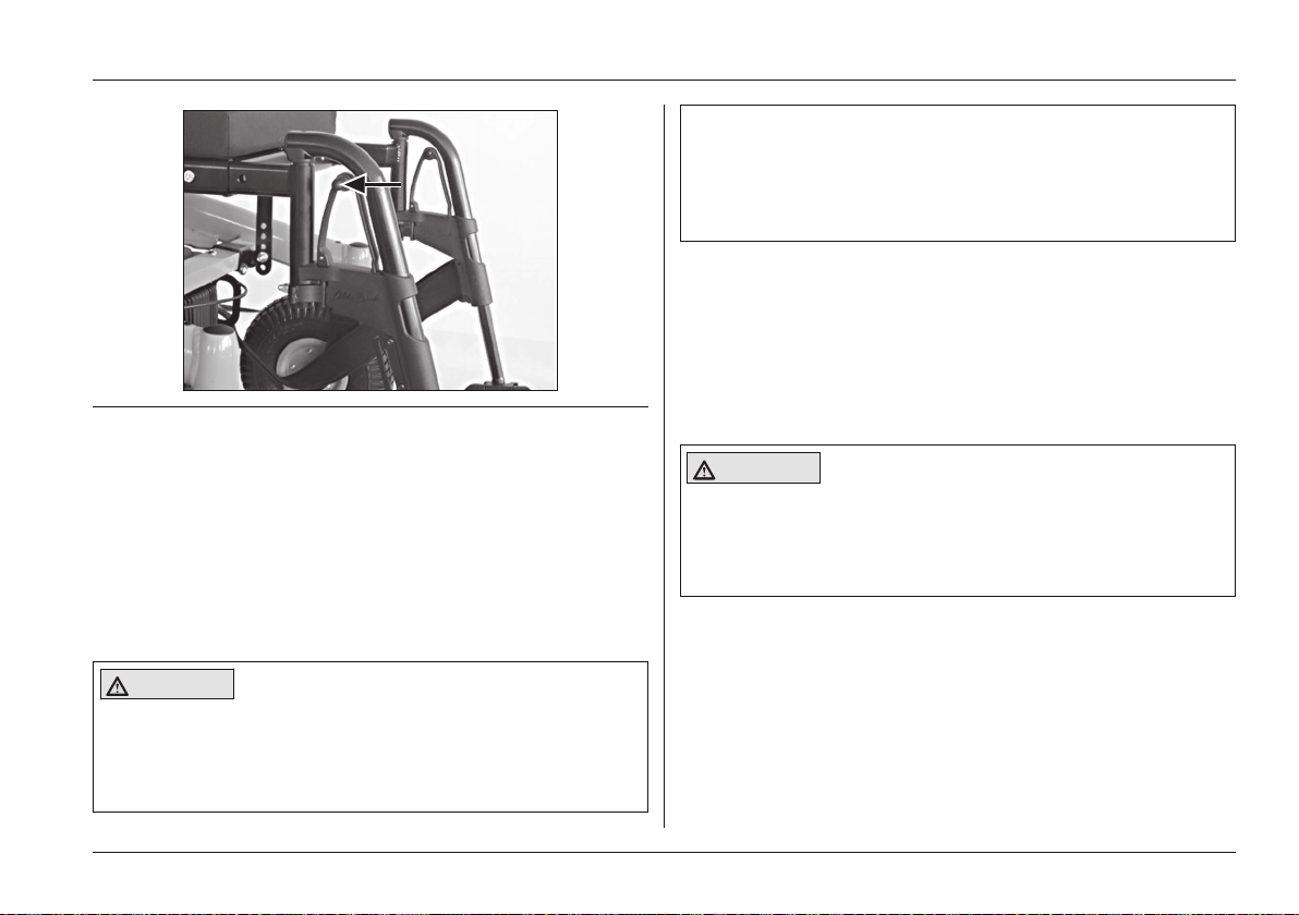
Fig. 10 Locking the footrest
Usage
► Note that the armrests are not capable of bearing full
body weight, and therefore must not be used for get
ting into or out of the wheelchair.
► Ensure that your limbs are not in the danger area when
swinging the footrests out or in.
The modular design of the power wheelchair and the ease
with which you can remove the side panels and footrests
make it easy to get into and out of the wheelchair from the
side or from the front.
Users can choose the method for getting into and out of the
wheelchair which is most suitable for them.
Getting in from the front
Installing the footrests
Proceed as follows if a footrest must be installed:
1) Hook the footrest into the holder from above.
2) Swing the footrest forward until the footrest lock
engages.
3) Hook the calf band into the holder.
6.3 Getting in / transfer
CAUTION
Getting in and out incorrectly
Risk of falling, tipping, pinching, crushing
► Turn the control unit off while getting in and out, in
order to avoid accidental driving.
CAUTION
Exposed pinch points
Pinching, crushing of fingers
► Ensure that your fingers are not in the danger area
when flipping the footrests up or down.
1) Place the seat in the horizontal position.
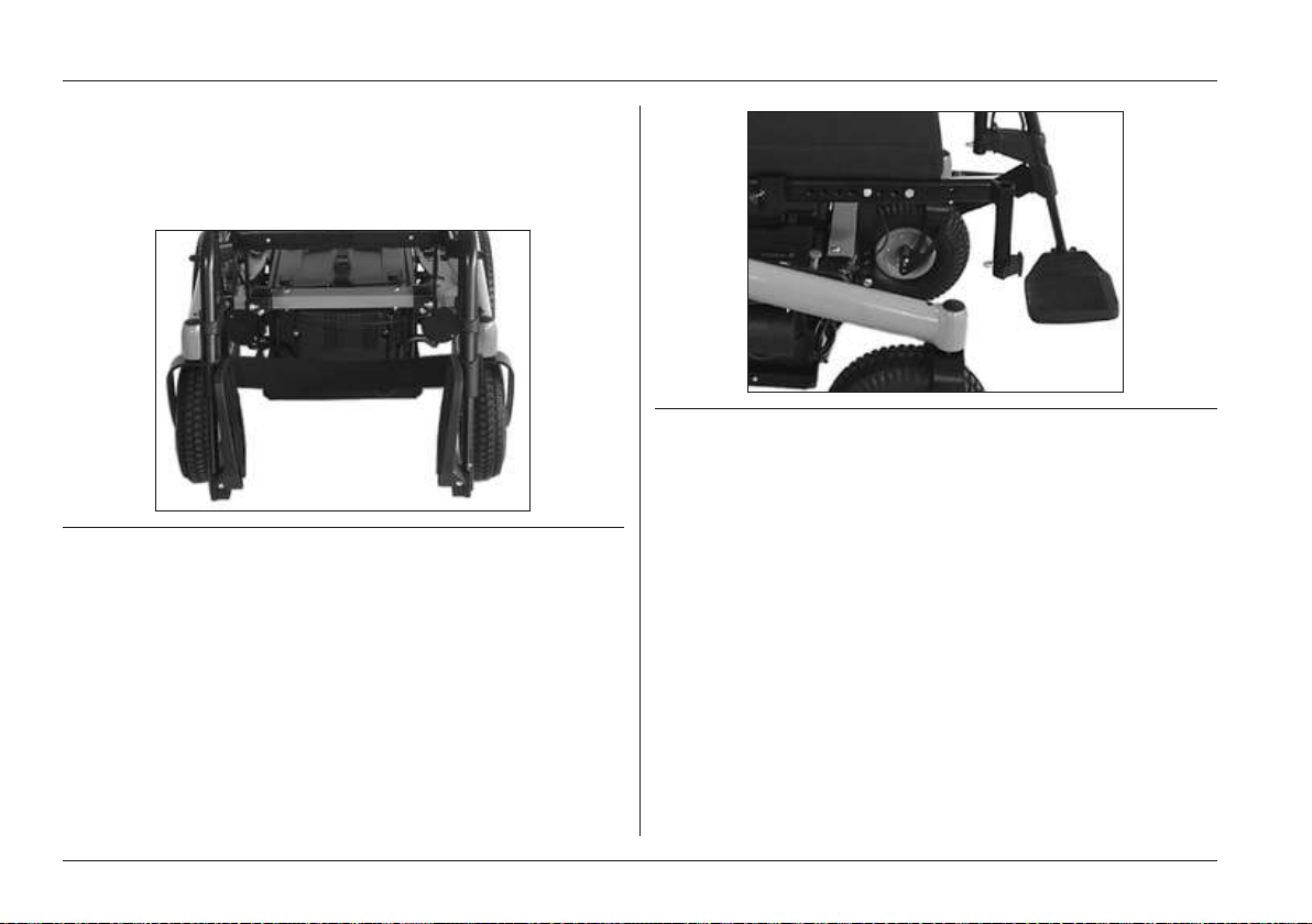
2) Flip the footrests up (see Fig.11) or remove them to
gain a larger entry and exit area (see Fig.10). Removing
the footrests increases the available entry or exit area
(see Fig.12).
3) Have an attendant assist you or use a transfer lifter to
get into and out of the power wheelchair.
Ottobock | 21B500 classic/advanced
Page 22
Usage
4) Flip the footrest down or reinstall it and flip it down (see
Page20).
5) Put the lap belt on when necessary (when driving on the
road).
Fig. 11 Footrest flipped up
Fig. 12 Footrest removed
Getting in from the side
1) Place the seat in the horizontal position.
2) Bring the power wheelchair as close as possible to
where the user is sitting.
3) Remove the side panel (see Page19).
INFORMATION: If the control panel is on the side
from which the user is getting into the wheelchair,
it can be removed and laid onto the seat.
4) Remove the footrest if necessary (see Fig.10).
5) Slide onto the seat from the side.
INFORMATION: A ramp makes it easier to get into
and out of the wheelchair from the side.
6) Install the side panel (see Page19).
22 | Ottobock B500 classic/advanced
Page 23
7) Put the lap belt on when necessary (when driving on the
road).
6.4 Control unit
CAUTION
Uncontrolled driving behaviour due to interference
from electromagnetic fields
Risk of falling, tipping, collision with persons or nearby
objects
► Switch all mobile devices off while driving.
► Turn the control unit off when it is not needed.
The power wheelchair is controlled by an enAble40 or
enAble50 control unit.
Because the control unit is programmable, it can be adap
ted to the personal requirements of the user; e.g. the speed,
acceleration and deceleration values can all be adapted.
6.4.1 Control Panel
The power wheelchair is operated using the control panel.
The control panel consists of a keypad, an LCD display and
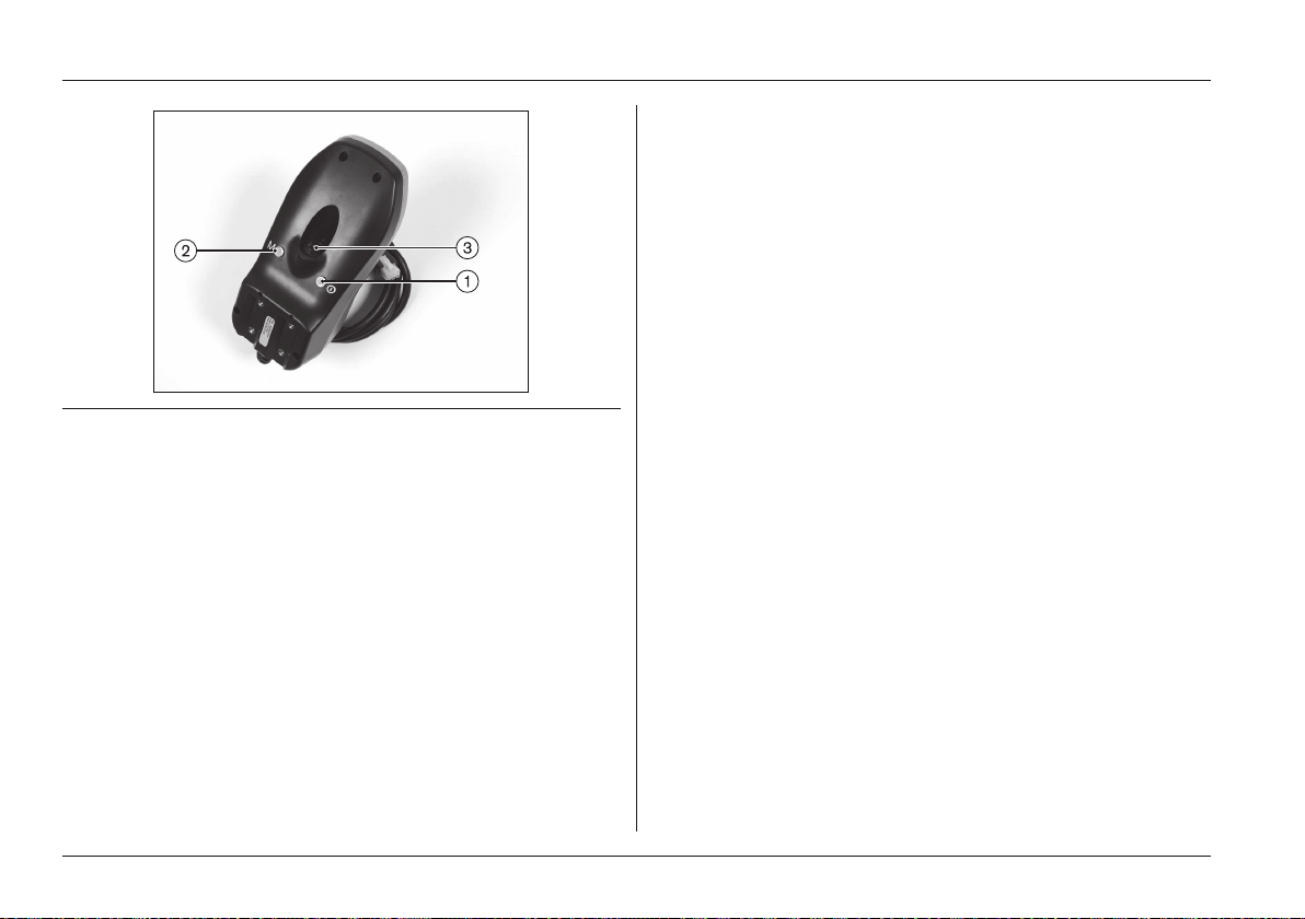
a joystick. The charging/programming receptacle and two
inputs for external buttons are located on the underside.
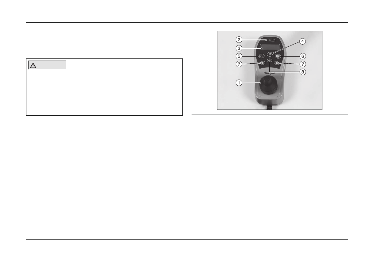
The control panel is used to switch the power wheelchair on
and off, enter driving commands and display the current
statuses of certain functions and components.
Usage
Fig. 13 enAble50 control panel (identical to: enAble40)
1 Joystick 5 [Warning Flasher On/Off]
button
2 [On/Off] button 6 [Horn] button
3 LCD display 7 [Direction Indicator
Left/Right] button
4 [Mode] button 8 [Lights On/Off] button
Ottobock | 23B500 classic/advanced
Page 24
Usage
Fig. 14 Connections on the underside
[Mode] Button
Pressing the button briefly increases/decreases the speed
level. After reaching the maximum speed level, you can
change back to speed level 1 by pressing the button again
(1-2-3-4-5-1-…).
Holding the button (for at least 2 seconds) switches the con
trol unit into the Power Seat Functions menu.
[Warning Flasher On/Off] Button
All 4 warning flashers are activated/deactivated when this
button is pressed.
[Horn] Button
The horn will sound as long as the button is pressed.
1 External [On/Off] button connection (only on enAble50)
2 External [Mode] button connection (only on enAble50)
3 Charging/programming receptacle
[Direction Indicator Left] and [Direction Indicator Right]
Button
Pressing these buttons activates/deactivates the respective
front and rear direction indicators. The direction indicator
6.4.2 Buttons and display functions
Joystick
The speed and driving direction are controlled with the joy
stick. When a seat option is activated, the joystick operates
this seat option.
[On/Off] Button
Holding this button turns the power wheelchair on or off and
activates/deactivates the drive-away lock.
lights turn off automatically after 20 seconds.
[Lights On/Off] Button
The front and rear lights are activated/deactivated by press
ing the button.
LCD Display
The LCD display is the communication interface between
the user and the control unit. It indicates the selected speed
level, the remaining battery capacity, the status of power
options as well as warnings and errors. All display symbols
are displayed while the power wheelchair turns on.
24 | Ottobock B500 classic/advanced
Page 25
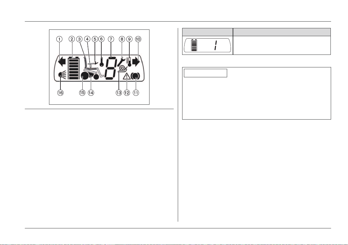
Fig. 15 LCD display with all symbols
1 Direction indicator, left 9 Excess temperature
2 Battery capacity 10 Direction indicator, right
3 Power backrest 11 Drive wheel brake
4 Power seat tilt 12 Warning
5 Control Panel 13 Creeping speed
6 Drive-away lock 14 Power module
7 Speed level 15 Drive motor
8 Open-end wrench 16 Light
Selected speed level (LCD display)
After turning the control panel on, the LCD display indicates
the selected speed level and battery capacity in the Driving
menu:
Usage
Display Information
Right: Selected speed level = 1
Left: Battery capacity
Battery capacity (LCD display)
INFORMATION
At temperatures of < 0° the battery capacity drops by up to
35% in relation to the capacity for an outside temperature
of 20°. This shortens the range of the power wheelchair
accordingly. Moreover at low temperatures the battery
capacity displayed on the control panel can differ more sig
nificantly from the actual battery capacity.
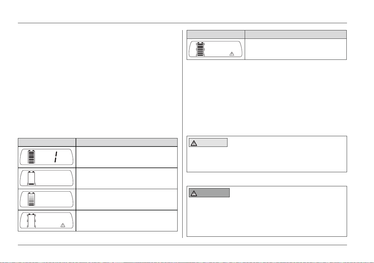
The 'Battery Capacity' LCD display (see Fig.15, item 2) is
divided into seven segments which indicate the current bat
tery capacity:
• Immediately after the power wheelchair is switched on,
the battery indicator shows the battery charge level that
was saved before the wheelchair was last switched off.
• After brief operation the battery indicator shows the
exact battery status.
• A charge of 100% corresponds to seven segments on
the battery symbol.
• As the remaining battery capacity decreases, the LCD
segments turn off one by one.
Ottobock | 25B500 classic/advanced
Page 26
Usage
• If only one blinking segment is shown on the LCD dis
play, then the battery is in a low voltage state. Because
further use will result in battery damage, the warning
signal is also shown on the LCD display. The battery
must be charged immediately.
• If all seven segments on the LCD display are flashing,
this means that the battery is in an overvoltage state.
Because further use will result in battery damage, the
warning signal is also shown on the LCD display.
Please continue to drive at low speed only.
• The charging process is indicated by the battery seg
ments lighting up one after the other. The driving func
tion is blocked when the battery is charging.
Battery indicator on the control panel
Display Information
Full battery capacity (right: selected
speed level)
Low battery capacity
Charging process with drive-away
lock
Battery undervoltage with warning
symbol
Display Information
Battery overvoltage with warning
symbol
Further LCD display functions
Further LCD display symbols are described in the following
sections:
• See section 'Usage' > 'Drive-Away Lock'
• See section 'Usage' > 'Seat Functions'
• See section 'Maintenance/Repair' > 'Troubleshooting'
6.5 Driving Functions
6.5.1 Safety Instructions
CAUTION
Lack of driving experience
Risk of tipping, falling
► Practise using the product on level, open ground first.
Hazards while driving
WARNING
Uncontrolled rolling
Risk of collision with persons nearby objects
► Note the lack of brake functionality when the brake is
deactivated. The brake function may only be released
in the presence of an attendant.
26 | Ottobock B500 classic/advanced
Page 27
Usage
► Should the user be unable to release the brake him
self, the brake can be released by the attendant.
► Note that when the power wheelchair is moved on an
incline, the attendant must provide the required brake
force.
► Lock the brake every time before parking the power
wheelchair.
CAUTION
Insufficient support of the seated person
Risk of falling out of the power wheelchair
► Always wear the safety belt / lap belt when driving in
public.
CAUTION
Risk of uncontrolled driving behaviour
Risk of falling, tipping, collision with persons or nearby
objects
► If any faults, defects or other hazards that can lead to
personal injury are detected, the product must be
taken out of service immediately.
► Contact your authorised specialist dealer if uncon
trolled movement of the product occurs due to a mal
function.
CAUTION
Driving in the dark
Risk of an accident involving other traffic, collision with
persons or objects in the vicinity.
► Wear bright clothing or clothing with reflectors.
► Turn the lights on (if available) or install active lights.
► Ensure that the reflectors on the power wheelchair are
clearly visible.
CAUTION
Use of mobile devices with electromagnetic emis
sions (e.g., mobile phones)
Falling, collision with persons or objects due to interfer
ence with the control signals
► Turn all mobile devices off while driving, since the driv
ing characteristics of the product are affected by elec
tromagnetic fields.
► Turn the control unit off when it is not required, since
the product may generate electromagnetic fields that
can cause interference with other devices. The product
has been tested according to EMC regulations.
► Notwithstanding compliance with all applicable EMC
directives and standards, the product can be affected
by interference from other electric devices (e.g.,
department store EAS systems) or cause interference
with such devices. If this occurs, move your product
outside the interference range.
Ottobock | 27B500 classic/advanced
Page 28
Usage
Danger during use of public transportation, elevators,
lifting platforms
WARNING
Use of public transportation, elevators, lifting plat
forms
Risk of tipping, collision with persons or objects in the
vicinity
► Always turn the power wheelchair control unit off when
using buses, trains, elevators, or lifting platforms.
► Engage the brake.
Hazards due to defective tyres
CAUTION
Defective tyres
Accidents/falling due to poor traction, reduced braking
force or lack of manoeuvrability
► Maintain sufficient tyre pressure. The correct tyre pres
sure is printed on the casing.
► Ensure that the drive wheels have the same pressure.
► Ensure that the tyres have sufficient tread depth. The
tyres must be changed when the tread depth is less
than 1 mm.
► Avoid parking outside and in direct sunlight (UV radi
ation) since this causes the tyres to age quickly. The
manufacturer recommends replacing the tyres every
2years regardless of the amount of wear.
► Always maintain sufficient clearance from sources of
heat. If the product is parked for an extended period of
time or the tyres overheat (e.g., in the vicinity of radiat
ors or in case of exposure to strong sunlight behind
glass), the tyres may become permanently deformed.
► Move your power wheelchair frequently or have a way
to jack it up for storage.
Further Information
INFORMATION
During use of the power wheelchair, electrical discharges
(high voltage with low current; discharge via the user) may
occur which are caused by factors such as friction.
However, these do not represent a health hazard.
Electrostatic discharge may also occur if the power wheel
chair is equipped with puncture-proof tires. Retrofitting the
wheelchair with pneumatic tires can correct this problem.
6.5.2 Driving notes
General information:
• Beginners should always drive slowly.
• Always take curves slowly.
• Uncontrolled driving behaviour may occur on uneven
ground. Therefore the speed must always be adjusted to
the ground conditions.
28 | Ottobock B500 classic/advanced
Page 29
Usage
• Driving backwards should be limited to manoeuvring or
short distances on level ground.
Obstacles (steps, curbs):
• The critical obstacle height is 50mm. Obstacles higher
than 50mm may not be crossed.
• Always approach obstacles directly from the front (never
at an angle with only one caster wheel).
• Always reduce speed to cross over obstacles (e.g.
select speed level 1).
• Avoid jumping down from steps.
• Do not lean out of the wheelchair while crossing
obstacles
Inclines and downgrades:
• Ascending or descending slopes up to max. 9.5° (17 %)
is permitted. Driving on steeper inclines or downgrades
is not permitted. Otherwise safe braking is not ensured.
• In order to navigate downgrades safely, the speed must
be reduced according to the slope (e.g. select speed
level 1).
• Never drive downhill backwards.
All terrain driving:
The speed must be reduced in dangerous areas (e.g. select
speed level 1).
• Typical dangerous areas include:
– Narrow paths along waterways/slopes/cliffs (e.g.
quay walls, dikes, etc.)
– Cramped rooms or areas
– Steep downgrades (e.g. in the mountains, facing
streets)
– Unsurfaced areas (e.g. on construction sites, cross
ings, train crossings)
– Snow-covered or icy areas
6.5.3 Switching on and off
WARNING
Lack of brake functionality
Risk of falling, tipping, collision with persons or nearby
objects
► Ensure that the brake release lever is locked every time
before you drive.
► Check to ensure that the brakes are operational and
functional every time before you drive.
WARNING
Defective safety functions
Risk of falling, tipping, collision with persons or nearby
objects
► Before every use, ensure that the product and its safety
functions are in safe and proper condition.
Ottobock | 29B500 classic/advanced
Page 30
Usage
► Only use the product if all safety functions, e.g. the
automatic brakes, are functional.
INFORMATION
In dangerous situations, the product can be turned off at
any time using the on/off button. When the button is
pressed, the product brakes immediately and the electrical
functions cease. Malfunctions such as an insufficient sup
ply of power to the controls are recognised by the soft
ware, triggering an emergency stop or reducing the speed
of the product. A warning signal will also sound.
• Pressing the [On/Off] button (see Fig.13, item 2) turns
the power wheelchair control unit on or off. The power
wheelchair turns off automatically if the control unit is
not used for an extended period of time.
• The power wheelchair brakes automatically and comes
to a stop if it is turned off with the [On/Off] button while
driving.
• The specialist dealer can use the parameter settings to
specify the default speed level or default menu of the
power wheelchair after it is turned on, according to the
user's requirements.
6.5.4 Selecting the speed levels
• The power wheelchair has a programmable number of
speed levels (delivery condition = 5 speed levels).
• The speed level is increased by briefly pressing the
[Mode] button (see Fig.13, item 4).
• After reaching the maximum speed level, the next speed
level is 1.
• The LCD display indicates the selected speed level in
the Driving menu:
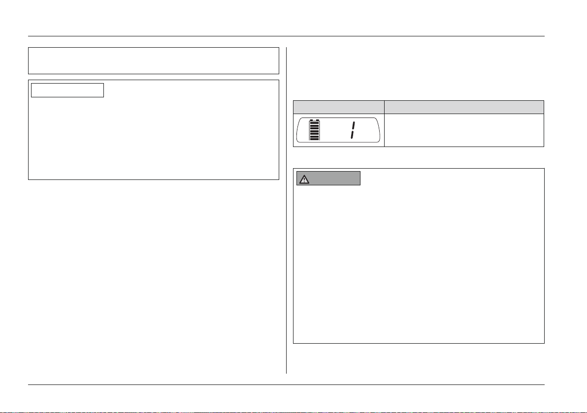
Display Information
Selected speed level = 1 (left: bat
tery capacity)
6.5.5 Driving
WARNING
Driving on slopes, over obstacles
Falling, tipping over due to user errors
► Only drive on slopes up to max. 9.5° (17%).
► Only cross obstacles which are not higher than 50mm
(2in).
► Do not cross over any obstacles while driving on
inclines or downgrades.
► Reduce speed when driving downhill (e.g. select
speed level 1).
► Only drive over obstacles such as steps or low curbs
at a reduced speed (max.3km/h).
► Approach obstacles at right angles and drive over
them at one go.
30 | Ottobock B500 classic/advanced
Page 31
Usage
► Only drive on inclines and over obstacles with the seat
tilt and seat height adjustments lowered and with a ver
tical backrest. The seat can be tilted back slightly when
driving downhill.
► Avoid embarking and disembarking on inclines and
slopes.
► Do not drive over stairs.
WARNING
Driving on unsuitable surfaces
Risk of falling, tipping
► Do not operate the power wheelchair on very smooth
surfaces (e.g. icy surfaces) or very rough surfaces
(e.g. gravel or rubble).
CAUTION
Insufficient support of the seated person
Risk of falling out of the power wheelchair
► Always wear the safety belt / lap belt when driving in
public.
INFORMATION
The control unit of the product switches to a safe mode at
elevated temperatures and after driving uphill for extended
periods of time, limiting the performance of the product.
The user is able to drive the product out of a hazardous
situation at any time. The product is fully functional again
once the unit has cooled down sufficiently (this may take
several minutes depending on the ambient temperature).
The power wheelchair is controlled by moving the joystick:
• The further the joystick is deflected from the centre posi
tion, the faster the power wheelchair will drive in this dir
ection.
• The maximum speed at full deflection of the joystick
depends on the selected speed level.
• Releasing the joystick automatically activates the brake
function, bringing the power wheelchair to a halt.
The mechanical brakes are activated automatically when the
power wheelchair comes to a stop so that it cannot roll.
6.5.6 Range
INFORMATION
► Information about the range of the power wheelchair
can be found in the chapter 'Technical Data'.
► Please note that the specified range was determined
under defined conditions in accordance with ISO
7176-4. In practice the range can be reduced by up to
50%.
The following factors influence the range of a power wheel
chair:
• Battery capacity
Ottobock | 31B500 classic/advanced
Page 32
Usage
• Age of the batteries
• Ambient temperature
• Driving conditions (e.g. terrain profile, condition of sur
face)
• Charging method
• Use of power options
• Body weight of user
6.5.7 Drive-away lock
INFORMATION
For the B500 advanced/B500 plus, the drive-away lock can
only be activated as described if the function was previ
ously enabled (see front inner cover). The factory default
setting can be changed by the specialist dealer.
Please ask your specialist dealer about the setting selected
for your wheelchair.
The power wheelchair control unit features an electronic
drive-away lock. This function is activated/deactivated via
the control panel.
The drive-away lock can only be activated or deactivated if
the "Drive-away lock" parameter is set to "Function
enabled". Unless otherwise specified in the order, the driveaway lock is set to "Function disabled" at the factory.
If this setting needs to be changed, this is done by the
authorised person who fitted the wheelchair.
Activating the drive-away lock
► While the control unit is turned on, press and hold the
mode button for at least 5 seconds.
→ A short beep confirms that the drive-away lock was
activated.
INFORMATION: If keypress beeps are activated,
then the drive-away lock is only active after the
second beep.
→ The control unit turns itself off.
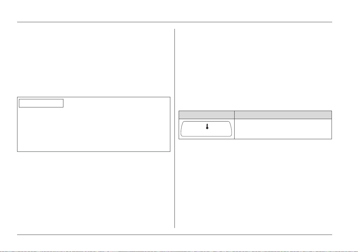
→ The key symbol on the LCD display indicates that the
drive-away lock is activated:
Display Information
Drive-away lock
Deactivating the drive-away lock
1) Push the [On/Off] button on the control panel.
→ The control unit is turned on. The LCD screen indic
ates that the drive-away lock is activated.
2) Push the joystick all the way forward until a beep
sounds.
3) Push the joystick all the way back until a beep sounds.
4) Release the joystick.
→ A long beep confirms that the driving function is
enabled.
32 | Ottobock B500 classic/advanced
Page 33

Usage
→ The battery indicator and speed level are shown on the
LCD screen.
→ The drive-away lock is deactivated and driving is
enabled.
Problem resolution
The drive-away lock remains active if the joystick is not
moved correctly.
1) Turn the control unit off in order to deactivate the driveaway lock again.
2) Turn the power wheelchair on.
3) Deactivate the drive-away lock again.
6.5.8 Steering lock
INFORMATION
For the models with enAble50 control units the steering
lock can only be activated as described below if the func
tion was previously enabled (see inside front cover). The
factory default setting can be changed by the specialist
dealer.
Please ask your specialist dealer about the setting selected
for you.
The enAble50 control unit in the power wheelchair may be
programmed with the optional 'Steering Lock' parameter.
If the steering lock is activated, the caster wheels or the
drive wheels (depending on the type) are set straight ahead.
This makes it easier to negotiate narrow ramps and to use
lifts:
• When the joystick is deflected forward, the power
wheelchair drives straight ahead.
• When the joystick is deflected backward, the power
wheelchair always drives straight back.
• Turning is not possible when the steering lock is activ
ated.
• The warning flasher lights flash when the steering lock
is activated (standard programming).
Activating the steering lock
1) Bring the power wheelchair to a full stop.
2) Push the [Warning Flasher On/Off] button.
→ The steering lock is activated.
→ All warning flasher lights flash (standard program
ming).
3) Move the joystick forward/backward. The power wheel
chair now drives straight ahead/back.
Deactivating the steering lock
1) Bring the power wheelchair to a full stop.
2) Push the [Warning Flasher On/Off] button.
→ The steering lock is deactivated.
→ All warning flasher lights stop flashing.
3) Move the joystick. The power wheelchair now drives in
the chosen direction without the steering lock.
Ottobock | 33B500 classic/advanced
Page 34
Usage
6.5.9 Adjusting the driving characteristics
WARNING
Incorrect configuration settings
Falling, tipping over, collision due to programming errors
► Programming may only be performed by qualified per
sonnel trained by the manufacturer. The manufacturer
of the product and the control unit manufacturer are
not liable in case of damage caused by programming
which was not performed properly and/or which was
not adjusted properly according to the user's abilities.
► Note that modified parameter settings in the configura
tion can lead to changes in driving characteristics. In
particular, changes to the speed, acceleration, braking
or joystick settings can lead to unexpected and there
fore uncontrollable driving characteristics and cause
an accident.
► After configuration/programming is complete, the user
must test the driving characteristics of the product
under the supervision of the qualified personnel.
Adjusting and setting the speed, acceleration and decelera
tion values to the individual user requirements is performed
exclusively by qualified personnel trained by the manufac
turer.
6.6 Activating/deactivating the brakes
WARNING
Uncontrolled rolling
Risk of collision with persons nearby objects
► Note the lack of brake functionality when the brake is
deactivated. The brake function may only be released
in the presence of an attendant.
► Should the user be unable to release the brake him
self, the brake can be released by the attendant.
► Note that when the power wheelchair is moved on an
incline, the attendant must provide the required brake
force.
► Lock the brake every time before parking the power
wheelchair.
WARNING
Improper maintenance, repair, or adjustment work on
the brake
Falling, tipping, collision with persons or nearby objects
► Repairs and adjustments to the brake may only be
made by qualified personnel trained by the manufac
turer. Incorrect settings can lead to a loss of braking
power.
It is possible to push the power wheelchair in case of con
trol unit failure or insufficient battery capacity. To do so, it is
34 | Ottobock B500 classic/advanced
Page 35
necessary to disable the brake using the release mechanism
described below.
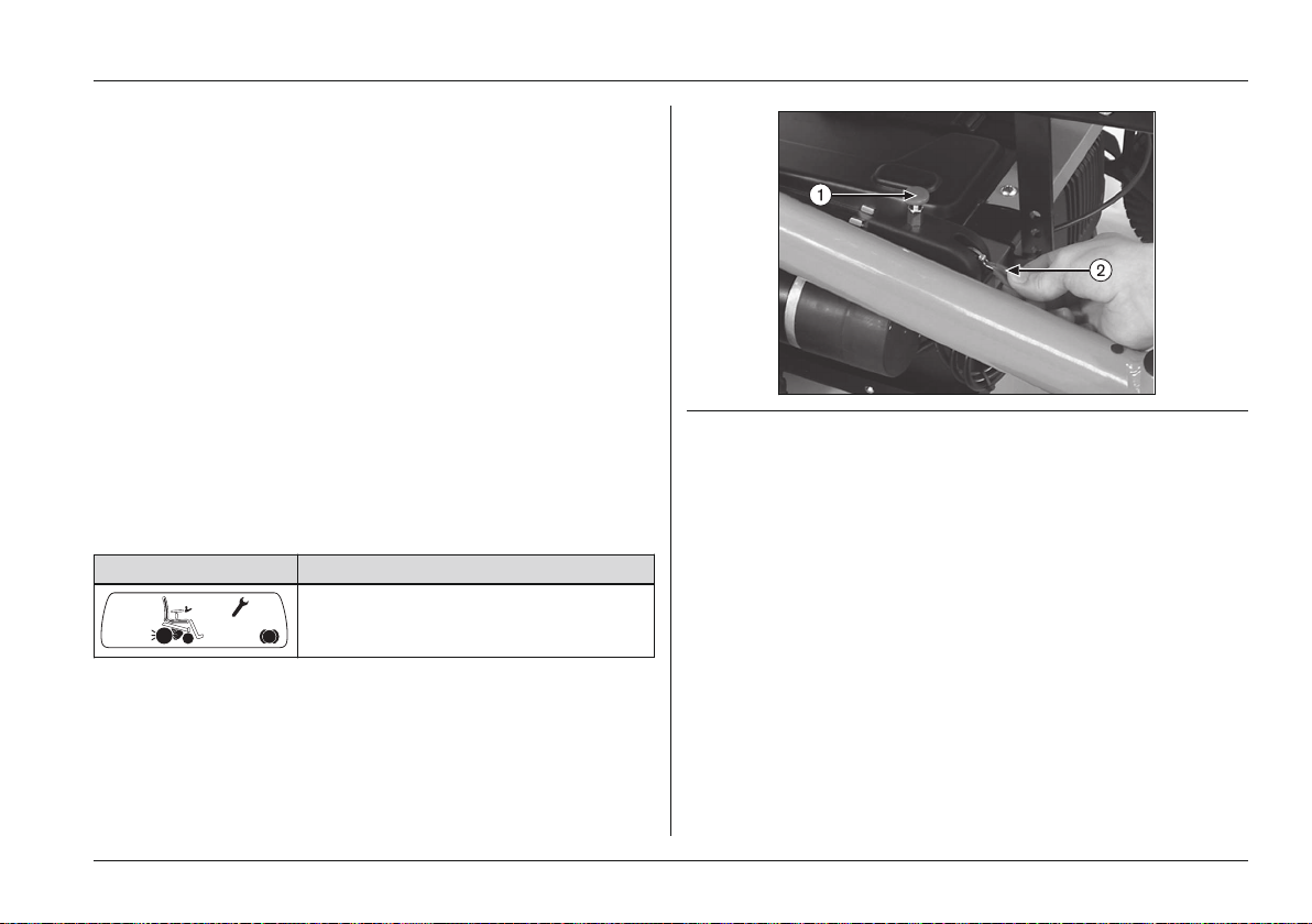
The brake release is located between the frame and seat, on
either the right or left side according to customer prefer
ence.
Disabling/deactivating the brake
1) Pull the brake release bolt up (see Fig.16, item 1).
→ The brake release lever (see Fig.16, item 2) is
unlocked.
2) Push the brake release lever forward until it engages.
→ The brake is disabled, all braking systems are turned
off.
→ The control unit will recognise that the brake has been
disabled and deactivate the driving function.
→ A warning will appear on the LCD monitor as soon as
the joystick is deflected:
Display Information
Brake is disabled
Usage
Fig. 16 Disabling the brake
1 Brake release bolt 2 Brake release lever
Enabling/activating the brake
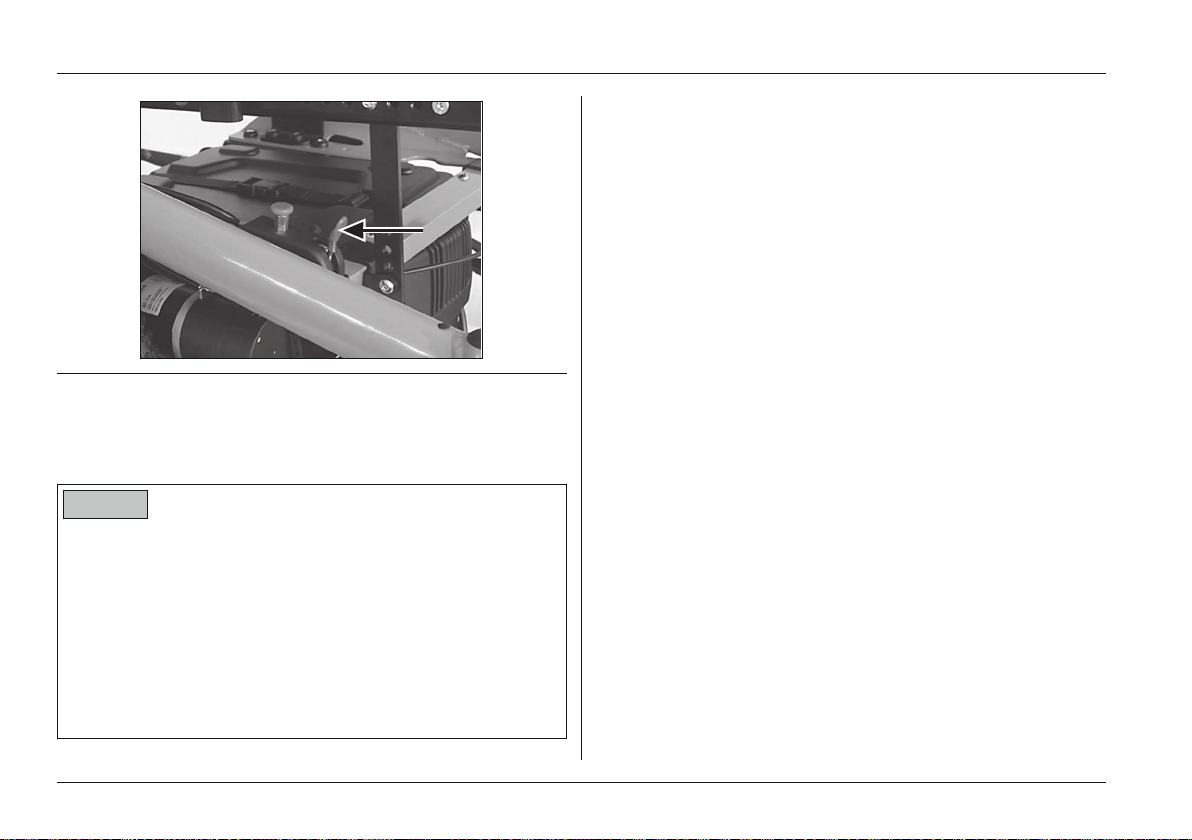
1) Push the brake release lever (see Fig.17, arrow) up
until the brake release bolts engage.
2) Turn the control unit off and on again.
→ The driving function is activated.
Ottobock | 35B500 classic/advanced
Page 36
Usage
Fig. 17 Enabling the brake
6.7 Batteries/charging process
6.7.1 Safety Instructions
NOTICE
Unauthorised battery replacement
Damage to the battery due to user error
► Replacing the battery or modifying the battery installa
tion position may only be performed by qualified per
sonnel trained by the manufacturer.
► The charging profile of the battery charger established
at the factory matches the batteries included in the
scope of delivery and may not be altered independ
ently.
6.7.2 General
The standard version of the power wheelchair is equipped
with two maintenance-free gel batteries with a total capacity
of 63Ah(C5).
The power wheelchair can optionally be equipped with two
AGM batteries with a total capacity of 63Ah(C5).
The batteries are located beneath the wheelchair seat in a
battery drawer. If the power wheelchair is not equipped with
a drive wheel suspension, then the batteries are located in a
tray.
Prolonged driving at the lower end of the battery indicator
results in deep discharge which causes battery damage. If
the power wheelchair is being driven when the battery is low
the control unit switches to creep speed to save power.
6.7.3 Battery charging information
The range of the power wheelchair is determined by the bat
tery capacity. The battery capacity is influenced by many
factors. In addition to the temperature, battery age and driv
ing conditions, the charging cycle also has a pronounced
effect on the capacity and therefore on the range.
At temperatures of < 0° the battery capacity drops by up to
35% in relation to the capacity for an outside temperature of
20°. This shortens the range of the power wheelchair
accordingly. Moreover the battery capacity displayed on the
control panel can differ more significantly from the actual
battery capacity.
36 | Ottobock B500 classic/advanced
Page 37

Usage
The following information should be observed for an optimal
charging cycle:
• The batteries can be charged at any time, regardless of
the remaining battery capacity.
• It takes about 10 hours until a discharged battery (only
1 flashing segment) is completely charged. When the
charging process is complete, the battery charger can
remain connected to the power wheelchair with no risk
of overcharging or damaging the battery. The battery
charger features a programmed recharging phase that
will maintain the battery capacity at the level that has
been reached.
• If the power wheelchair is used every day, the battery
should be charged every night.
• Never discharge the batteries completely (deep dis
charge).
• The batteries will gradually discharge if the wheelchair
is not used for extended periods of time. If the power
wheelchair is not used for an extended period, the bat
teries should be charged 1 x per week to maintain their
capacity.
• The fuse should be removed if the wheelchair is not
used for more than 3 days.
• The power wheelchair control unit must be switched off
while the batteries are charging to allow all of the char
ging current to be fed into the battery.
6.7.4 Battery charger
NOTICE
Improper use of the battery charger
Damage to the battery charger, damage to the battery due
to user error
► Only use battery chargers from Ottobock, which have
been verified and approved by the manufacturer for
use with the respective batteries (observe information
on the battery charger).
► Ensure that the information on the battery charger
nameplate matches the country-specific voltage of the
respective mains grid.
► Only use the battery charger within the specified tem
perature and humidity limits.
► Place the battery charger on a level surface.
► If you locate the battery charger near a window, pro
tect it from direct sunlight.
► Avoid overheating of the battery charger. Do not cover
the ventilation slits in the case.
► Switch the control unit off during the charging process
so that all of the charging current is fed into the bat
tery.
► Avoid dust, dirt and moisture.
► Only clean the battery charger with a dry cloth.
The battery charger is designed for maintenance-free and
low-maintenance batteries.
Ottobock | 37B500 classic/advanced
Page 38

Usage
Please see the instructions for use supplied with the battery
charger for further details on use and on the LED displays.
6.7.5 Charging the battery
WARNING
Discharge of explosive gases during battery charging
Burns due to explosion after a user error
► Ensure sufficient ventilation in enclosed spaces.
► Do not smoke or light fires.
► Sparks must be avoided.
► Do not cover the ventilation slits in the case.
► Only use battery chargers which have been verified
and approved by the manufacturer for use with the
respective batteries (observe information on the battery
charger). Non-observance may result in explosion of
the battery, resulting in a health hazard through contact
with the battery acid.
► Follow the battery manufacturer safety instructions.
► Wear protective goggles.
WARNING
Sparks
Risk of injury due to fire or explosion
► Switch the battery charger off and disconnect the
mains plug before you disconnect the battery.
NOTICE
Improper charging
Damage to the batteries due to user error
► Avoid deep discharge of the battery. The manufacturer
does not assume any liability for damage due to deep
discharge.
► Charge the battery as soon as possible if the last three
segments of the "Battery Capacity" LED indicator are
flashing.
► Charge the batteries weekly if the power wheelchair is
not used for an extended period of time.
1) Turn the control unit on the power wheelchair off.
2) Connect the charging plug of the battery charger to the
charging receptacle:
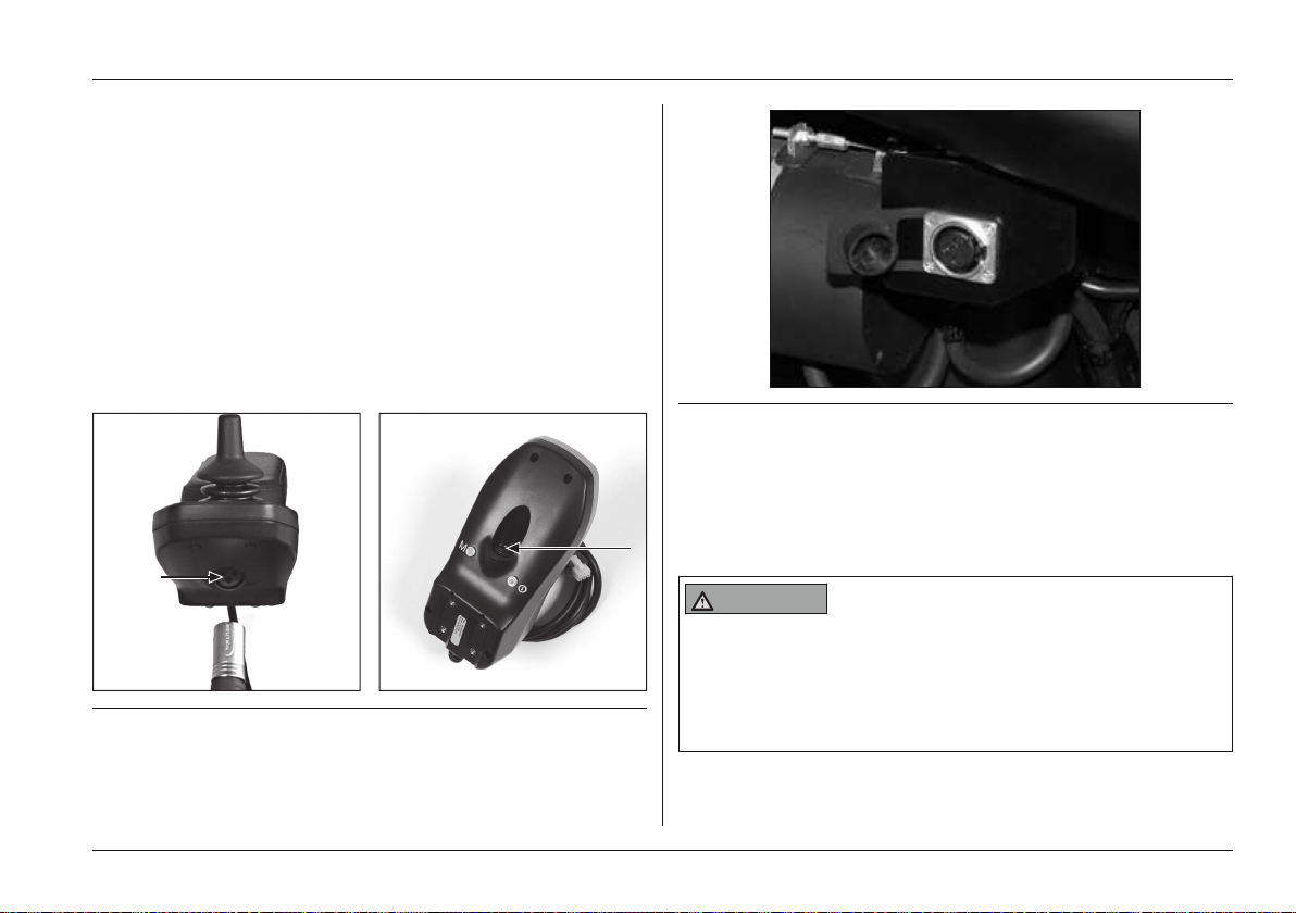
→ Version 1: Connection to the charging/program
ming receptacle on the power wheelchair control
panel (enAble40: see Fig.18, left; enAble50: see
Fig.18, right)
→ Version 2: Connection to the charging receptacle
on the power wheelchair (only for B500 advanced
model when equipped with seat height adjustment:
see Fig.19)
INFORMATION: Charging via this charging
receptacle is faster than via the control panel.
3) Connect the battery charger to the mains socket and
turn it on.
38 | Ottobock B500 classic/advanced
Page 39
→ The charging process starts automatically, and the
battery charge condition is indicated by the LED
indicator on the control panel and on the battery
charger.
4) Turn the battery charger off when the charging process
is complete.
5) Disconnect the battery charger mains plug.
6) Disconnect the battery charger plug from the control
panel.
7) Turn the power wheelchair control unit on.
→ The power wheelchair is ready to use.
Fig. 18 Charging/programming receptacle on the control pan
el
Usage
Fig. 19 Charging receptacle on power wheelchair
6.8 Power seat functions
The power wheelchair can be equipped with a range of
optional power seat functions.
6.8.1 Safety Instructions
WARNING
Driving with power seat options
Falling, tipping over due to user error
► Drive in street traffic only with the seat tilt and seat
height adjustments lowered and with a vertical back
rest.
Ottobock | 39B500 classic/advanced
Page 40
Usage
► Drive with the seat raised or with the seat tilt/back
angle adjustment activated only for short distances at
home. Always use the speed level 1 for this. Note that
the field of vision is limited when driving.
► Slightly tilt the seat to the rear when driving forwards
down inclines or over obstacles (e.g. curbs) and
reduce the speed.
► Use the seat height adjustment and the seat tilt only on
firm, level ground.
► Note that the climbing ability of power wheelchairs with
electric seat height adjustment and seat tilt is reduced.
Driving on inclines and slopes is permitted under ISO
7176-1 and 7176-2 with lowered seat height adjust
ment and lowered seat tilt up to max 6° (10%).
WARNING
Overloading
Falling, tipping over due to non-compliance with technical
data
► Note that the maximum permitted load of the power
wheelchair may be reduced when using the options
"Electric seat height adjustment" and "Electric seat tilt"
(see section "Technical Data").
WARNING
Exposed pinch points in the seat adjustment and lift
ing areas
Risk of pinching, crushing of limbs
► Note that when power seat options are used, inherent
pinch and shear points are located between the seat
frame and the power wheelchair frame.
► Ensure that no body parts, such as hands or feet, are
in the danger area while power seat options are used.
► Ensure that no interfering objects, such as clothing or
other obstacles, are in the danger area while power
seat options are used.
WARNING
Overloading of the actuators
Risk of falling, tipping, pinching, crushing of limbs
► Avoid overloading the actuators. Overloading may
cause the spindle nut to break, causing the seat to sag
or the backrest to flip back suddenly.
NOTICE
Improper use of power seat options
Risk of damage to the product
40 | Ottobock B500 classic/advanced
Page 41
Usage
► When using power seat options, note that the seat
function actuators are not designed for continuous
use, only for short-term use under limited loads (10%
load, 90% idle time).
► Observe the following guidelines: At maximum load
capacity, 10 seconds of activation time must be fol
lowed by approx. 90 seconds of idle time. The power
seat functions are considered independently of the
driving function for this purpose.
► Only activate the power seat functions if no fault or
error is present.
6.8.2 Power seat height adjustment
WARNING
Improper use of the seat height adjustment feature
Risk of falling or tipping over due to operator error
► Use the seat height adjustment feature only with the
backrest in the upright position.
► Drive in street traffic only with the seat height adjust
ment lowered.
► When driving with the seat height adjustment feature
raised, fasten the belts (lap belt, four-point belt) and do
not lean out beyond the seat surface.
► Ensure that creep speed is activated when the seat
height adjustment function is used. If this is not the
case, contact a specialist dealer immediately. Only use
the power wheelchair with the seat height adjustment
in its lowest position until the fault is rectified.
NOTICE
Lack of maintenance of the seat height adjustment
feature
Risk of damage to the power wheelchair
► Inspect the seat height adjustment feature for visible
signs of damage at least 1 x per month and ensure all
screw connections are tight.
► Check for correct tire pressure.
NOTICE
Risk of transportation damage.
Risk of damage to the power wheelchair
► Always lower the seat height adjustment feature fully
for loading or transportation.
INFORMATION
► Please also observe the safety instructions in the sec
tion "Power Seat Functions" > "Safety Instructions for
Use".
Ottobock | 41B500 classic/advanced
Page 42
Usage
► Observe the instructions for use in the sections "Power
Seat Functions" > "Control of Power Seat Functions"
and "Joystick and Display Functions".
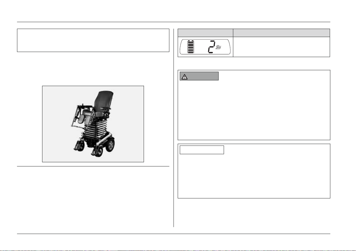
The power wheelchair can be equipped with a power seat
height adjustment feature. The seat height adjustment fea
ture increases the height of the seat by up to 40 cm, driven
by a motor.
Fig. 20 Seat with raised seat height adjustment feature
The driving function remains available even when the seat is
raised. The speed can be reduced (creep speed) if neces
sary when the seat is raised due to the decreased tipping
resistance. This is indicated on the control panel by the snail
symbol on the LCD display:
Display Information
Creep speed
6.8.3 Power seat tilt
WARNING
Incorrect seat tilt handling
Falling, tipping over due to user error
► Use the seat tilt feature only with the backrest in the
upright position.
► Drive in street traffic only with the seat tilt lowered.
► When driving with the seat tilt activated, fasten the
belts (lap belt, four-point belt) and do not lean out bey
ond the seat surface.
INFORMATION
► Please also observe the safety instructions in the sec
tion "Power Seat Functions" > "Safety Instructions for
Use".
► Observe the instructions for use in the sections "Power
Seat Functions" > "Control of Power Seat Functions"
and "Joystick and Display Functions".
The power wheelchair can be equipped with a power seat
tilt function. For more information on the specific equipment
of this power wheelchair, contact the qualified personnel.
42 | Ottobock B500 classic/advanced
Page 43
Usage
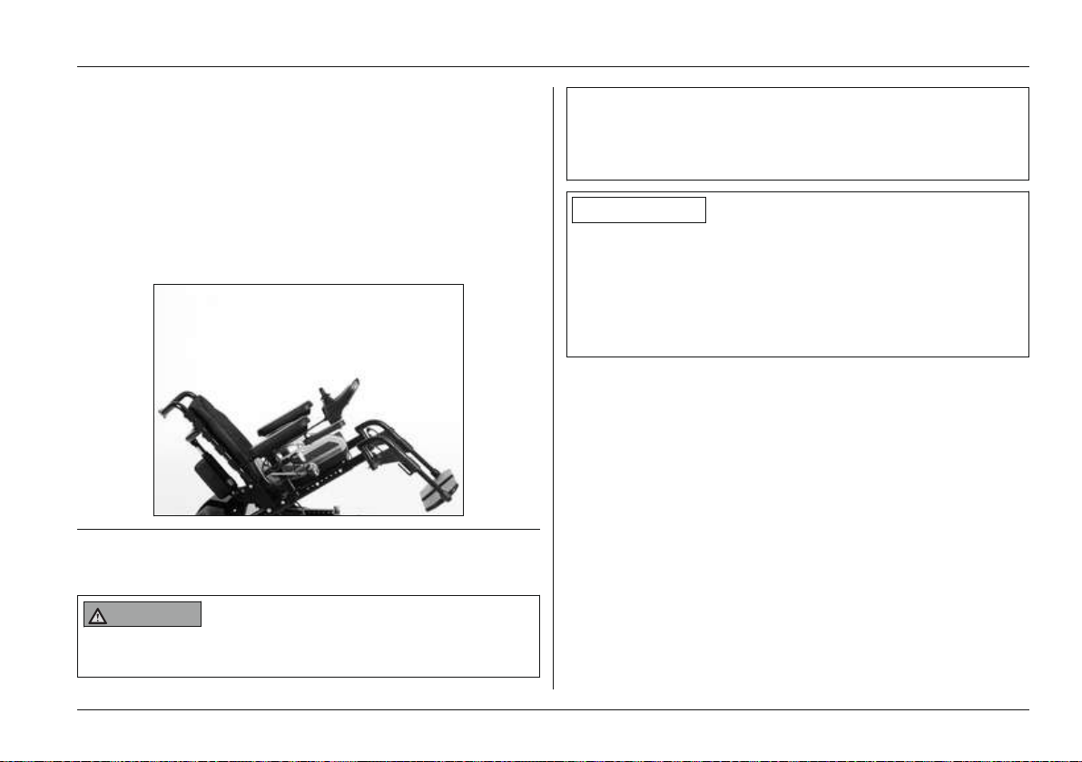
The power seat tilt function allows the seat to be tilted, for
example to relieve pressure. The power seat tilt feature is
available in 3 different versions:
• Power seat tilt up to 20° (B500 classic only)
• Power seat tilt up to 30°
• Power seat tilt up to 45°
The seat can be tilted back continuously to the angle spe
cified above.
Fig. 21 Power seat tilt
6.8.4 Power back angle adjustment
WARNING
Incorrect use of back angle adjustment
Falling, tipping over due to user error
► Drive in street traffic only with a vertical backrest.
► When driving with the back angle adjustment activ
ated, fasten the belts (lap belt, four-point belt) and do
not lean out beyond the seat surface.
INFORMATION
► Please also observe the safety instructions in the sec
tion "Power Seat Functions" > "Safety Instructions for
Use".
► Observe the instructions for use in the sections "Power
Seat Functions" > "Control of Power Seat Functions"
and "Joystick and Display Functions".
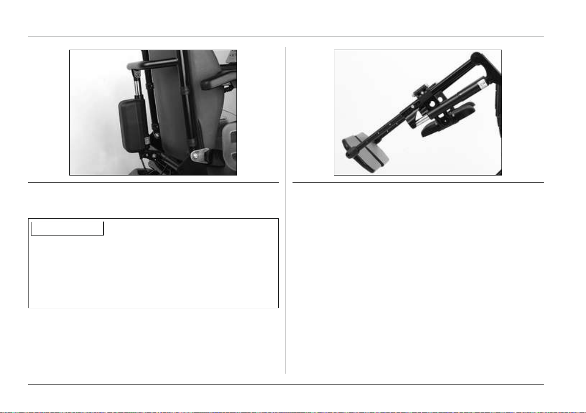
The power wheelchair with standard or contour seat can be
equipped with a power back angle adjustment feature.
The power back angle adjustment feature allows for continu
ous tilting of the backrest up to 30°.
Ottobock | 43B500 classic/advanced
Page 44
Usage
Fig. 22 Power back angle adjustment
6.8.5 Power footrests
INFORMATION
► Please also observe the safety instructions in the sec
tion "Power Seat Functions" > "Safety Instructions for
Fig. 23 Power footrest flipped up
The footplates can be flipped up to increase the entry and
exit area.
In addition, the electrically adjustable footrests can be
removed from their brackets and lifted up (see Fig.24, item
1).
Use".
► Observe the instructions for use in the sections "Power
Seat Functions" > "Control of Power Seat Functions"
and "Joystick and Display Functions".
To avoid constant pressure or to ensure anti-shock support,
the power wheelchair can be equipped with power
adjustable footrests. The footrests can be activated individu
ally or at the same time, depending on the configuration.
44 | Ottobock B500 classic/advanced
Page 45
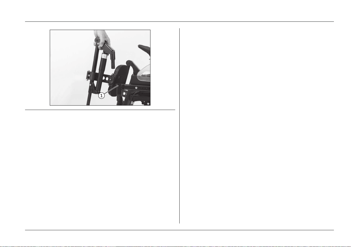
Fig. 24 Removing the footrest
6.8.6 Controlling power seat functions
• Holding the [Mode] button (approx. 2 seconds; see
Fig.13) activates control of the first power seat function,
e.g. the power back angle adjustment or seat tilt.
• The LCD display indicates the currently selected seat
function (see following chapter "Joystick and Display
Functions").
• To switch between the various seat functions, press the
[Mode] button briefly or move the joystick to the right.
• Once a seat function is selected, it is activated by mov
ing the joystick forward or backward.
• The electric motor moves the seat function as long as
the joystick is deflected, and stops at the end positions.
Usage
• Holding the [Mode] button again (approx. 2 seconds;
see Fig.13) deactivates the seat function in the selected
position. The driving function is available again, and the
speed level indicator is lit.
Ottobock | 45B500 classic/advanced
Page 46
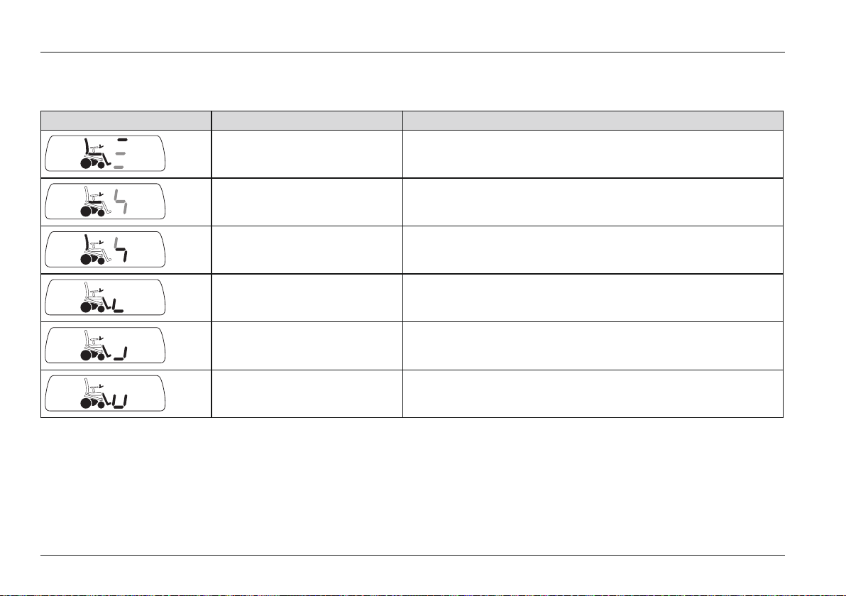
Usage
6.8.7 Joystick and display functions
The following power seat functions can be controlled with the joystick:
Display Seat function Joystick* deflection
Power seat height adjustment Forward: Seat surface moves up
Back: Seat surface moves down
Power seat tilt** Back: Seat slowly tips back
Forward: Seat slowly tips toward the horizontal position
Power back angle adjustment Forward: Backrest tilts forward
Back: Backrest tilts backward
Power footrest - left Forward: left footrest moves forward
Back: Left footrest moves back
Power footrest - right Forward: Right footrest moves forward
Back: Right footrest moves back
Power footrests, coupled Forward: Both footrests move forward
Back: Both footrests move back
* Deflection direction can be modified by the specialist dealer; ** Seat surface and backrest
46 | Ottobock B500 classic/advanced
Page 47
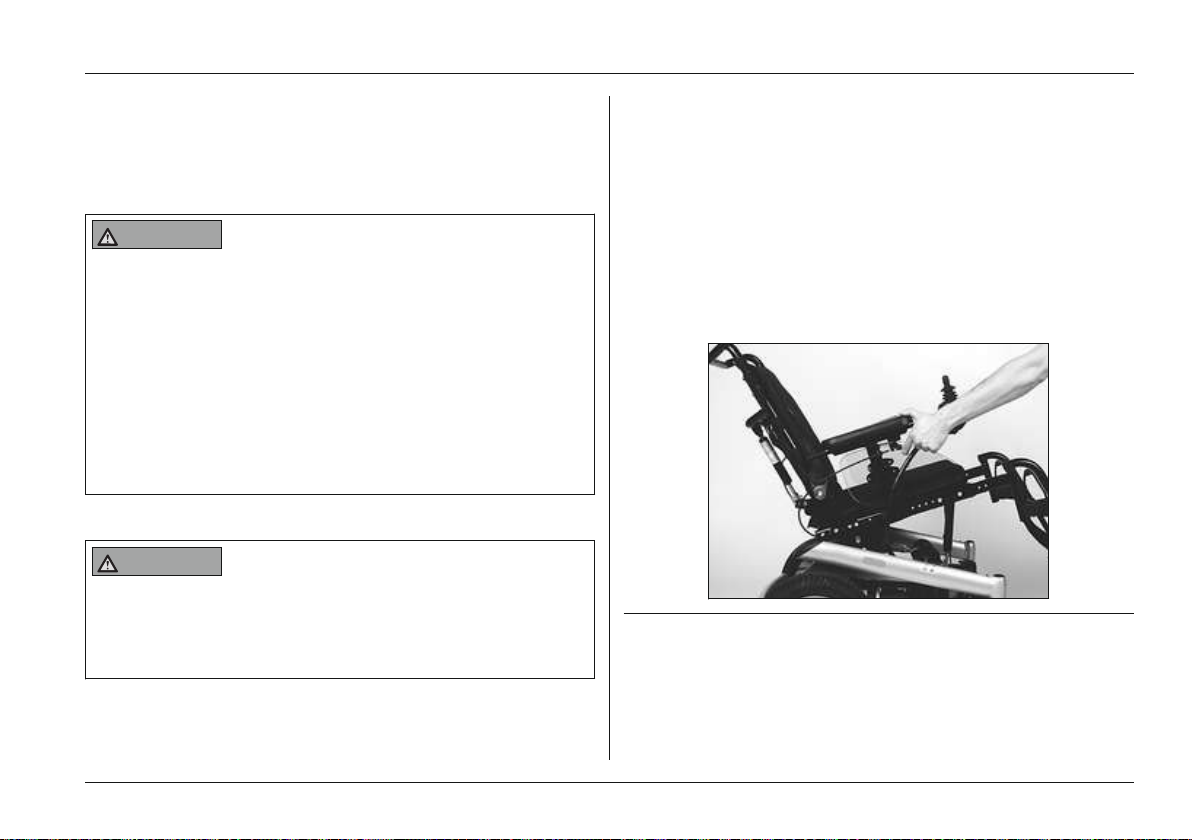
Usage
6.9 Manual seat functions
The power wheelchair can be equipped with a range of
optional manual seat functions.
6.9.1 Safety Instructions
WARNING
Exposed pinch points in the seat adjustment area
Risk of pinching, crushing of limbs
► Note that when manual seat options are used, inherent
pinch and shear points are located between the seat
frame and the power wheelchair frame.
► Ensure that no body parts, such as hands or feet, are
in the danger area while manual seat options are used.
► Ensure that no interfering objects, such as clothing or
other obstacles, are in the danger area while manual
seat options are used.
6.9.2 Manual seat tilt
WARNING
Unintentional lowering of the seat tilt
Risk of pinching, crushing of limbs
► Note that the seat can drop suddenly if the release
lever is operated while the seat is tilted.
The power wheelchair with standard or contour seat can be
equipped with a manual seat tilt function.
The manual seat tilt function allows the seat to be tilted, for
example to relief pressure. The seat can be tilted back con
tinuously by up to 20°.
Tilting the seat back
1) Activate the release lever on the armrest (see Fig.25).
2) Move the seat to the desired angle.
3) Let go of the release lever.
→ The seat is tilted back.
The seat is easier to tilt if the backrest is tilted back.
Fig. 25 Tilting the seat manually
6.9.3 Manual back angle adjustment
The power wheelchair with standard or contour seat can be
equipped with a manual back angle adjustment function.
Ottobock | 47B500 classic/advanced
Page 48
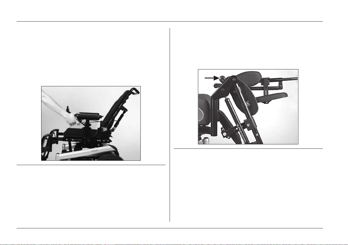
Usage
The manual back angle adjustment function allows for tilting
of the backrest up to 30°.
Adjusting the back angle
1) Activate the release lever on the armrest (see Fig.26).
2) Move the backrest to the desired position.
3) Let go of the release lever.
→ The backrest is adjusted.
Fig. 26 Adjusting the back angle manually
6.9.4 Manual elevating footrests
The power wheelchair can be equipped with manual elevat
ing footrests.
The manual elevating footrests make it possible to prevent a
constant pressure load or to provide anti-shock support.
Swivelling the footrest
1) Activate the release lever on the footrest (see Fig.27).
2) Move the footrest to the desired position.
3) Let go of the release lever.
→ The footrest is adjusted.
Fig. 27 Manual elevating footrest
6.10 Additional seat options
The power wheelchair can be equipped with a range of oth
er seat options.
6.10.1 Contour seat
Compared to the standard seat, the contour seat provides
the user with improved comfort and lateral support.
48 | Ottobock B500 classic/advanced
Page 49
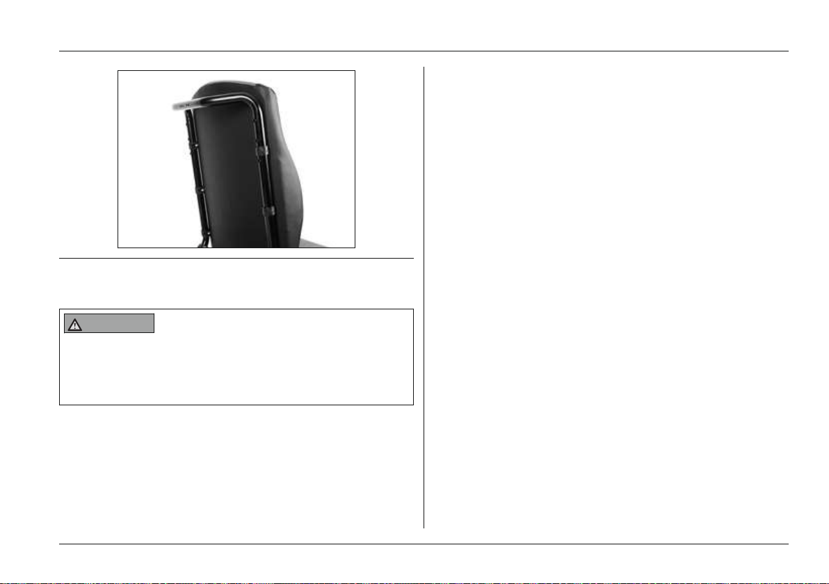
Fig. 28 Contour seat
6.10.2 Recaro® seat
WARNING
Incorrect Recaro® Seat settings
Risk of falling, tipping
► Note that the maximum backrest angle is 30° while
standing and 20° while driving.
The power wheelchair can be equipped with various
Recaro® seat models.
They provide individually adjustable, comprehensive seating
comfort.
Usage
Folding the backrest forward (reducing the
transportation size)
1) Pull the release handle on the Recaro® seat (see Fig.4,
item 1) up. The release handle is located on the side of
the backrest.
2) Fold the backrest forward.
3) Let go of the release handle.
→ The backrest is folded forward.
Folding the backrest up
► Fold the backrest up until the release handle is securely
engaged.
→ The backrest is folded up.
Removing the headrest
Two people are required to remove the headrest.
1) 1st person: Find the release points on the Recaro® seat
below the cover (see Fig.29) and push them at the
same time.
2) 2nd person: Pull the headrest up and out.
→ The headrest is removed.
Ottobock | 49B500 classic/advanced
Page 50
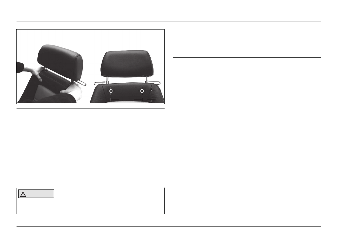
180
10
Usage
Fig. 29 Image showing the release points
Removing the Recaro® seat from the mobility base
1) Loosen the left and right locking bolts on the seat frame.
To do this, pull the release strap under the seat bottom
forward and hold it (see Fig.30, item1).
2) To release the rear seat clip from the bracket, tip and
push the seat back slightly.
3) Remove the Recaro® seat.
→ The Recaro® seat has been removed.
Attaching the Recaro® seat to the mobility base
► During installation of the Recaro seat, ensure that the
seat clip is engaged firmly in the clips.
► Ensure that the front locking bolts are engaged up to
the key ring.
1) Set the back edge of the Recaro® seat onto the end of
the seat frame.
2) Push the seat forward until the rear seat clip protrudes
into the bracket.
3) Tip the seat forward until the locking bolts engage with
the seat frame (see Fig.30, item2).
CAUTION! Visually inspect and shake the seat to
ensure secure locking.
→ The Recaro® seat is installed.
CAUTION
Recaro® seat not locked in place
Risk of tipping
50 | Ottobock B500 classic/advanced
Page 51
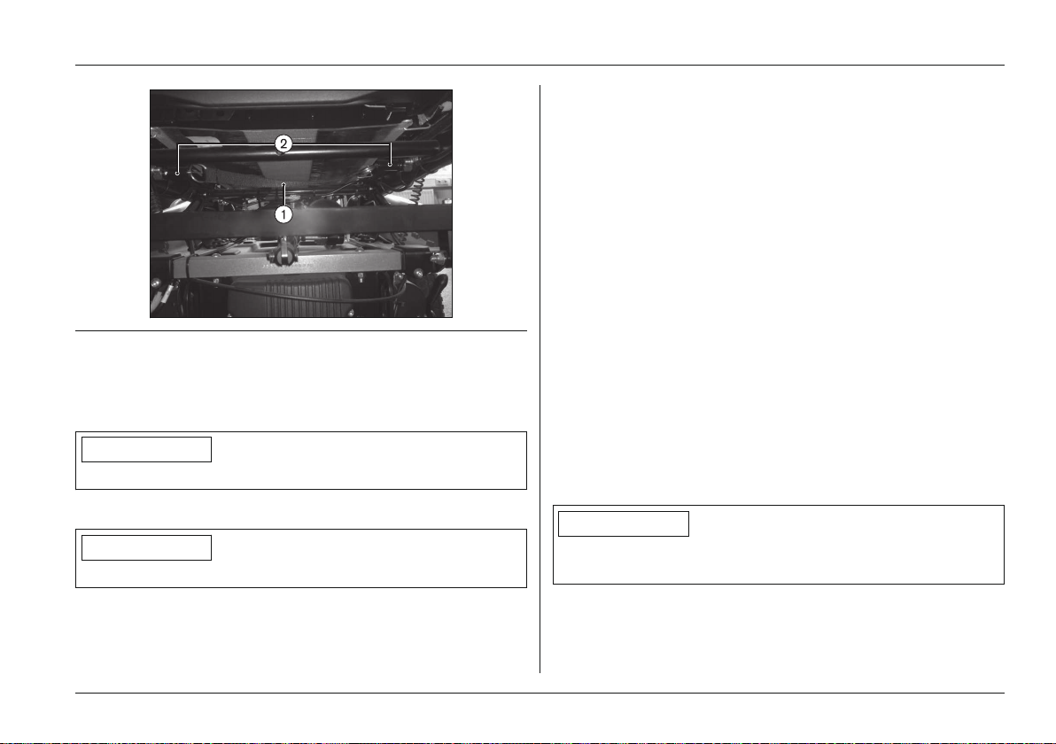
Usage
→ Both lateral supports are moved apart.
Adjusting the pads
The seat surfaces X and W are equipped with a pull-out pad
at the front of the seat bottom. The adjustment lever for the
pad is located below the seat bottom.
1) Pull the pad adjustment lever up and hold it there.
2) Move the pad to the desired position.
3) Release the adjustment lever and let it engage.
→ The adjustment lever is in a safe position if it engages
audibly and has returned to its initial position.
Fig. 30 Releasing/locking the Recaro® seat
1 Release strap 2 Locking bolts
Adjusting the Recaro® seat
INFORMATION
To adjust the back angle of the Recaro® seat: see Page15.
Adjusting the lateral supports in the lumbar region
INFORMATION
This information only applies to the Recaro® LT model.
1) Turn the knob on the side of the backrest forward.
→ Both lateral supports are moved closer together.
2) Turn the knob on the side of the backrest backwards.
Adjusting the headrest
The height and tilt angle of the headrest are adjustable.
6.10.3 Headrest
The manufacturer offers the option of equipping the stand
ard and contour seats with a headrest.
The bracket for attaching the headrest mounting kit is
attached with an adapter which is mounted to the back
frame.
INFORMATION
See the manufacturer documentation for information on
attaching the mounting kit.
Ottobock | 51B500 classic/advanced
Page 52
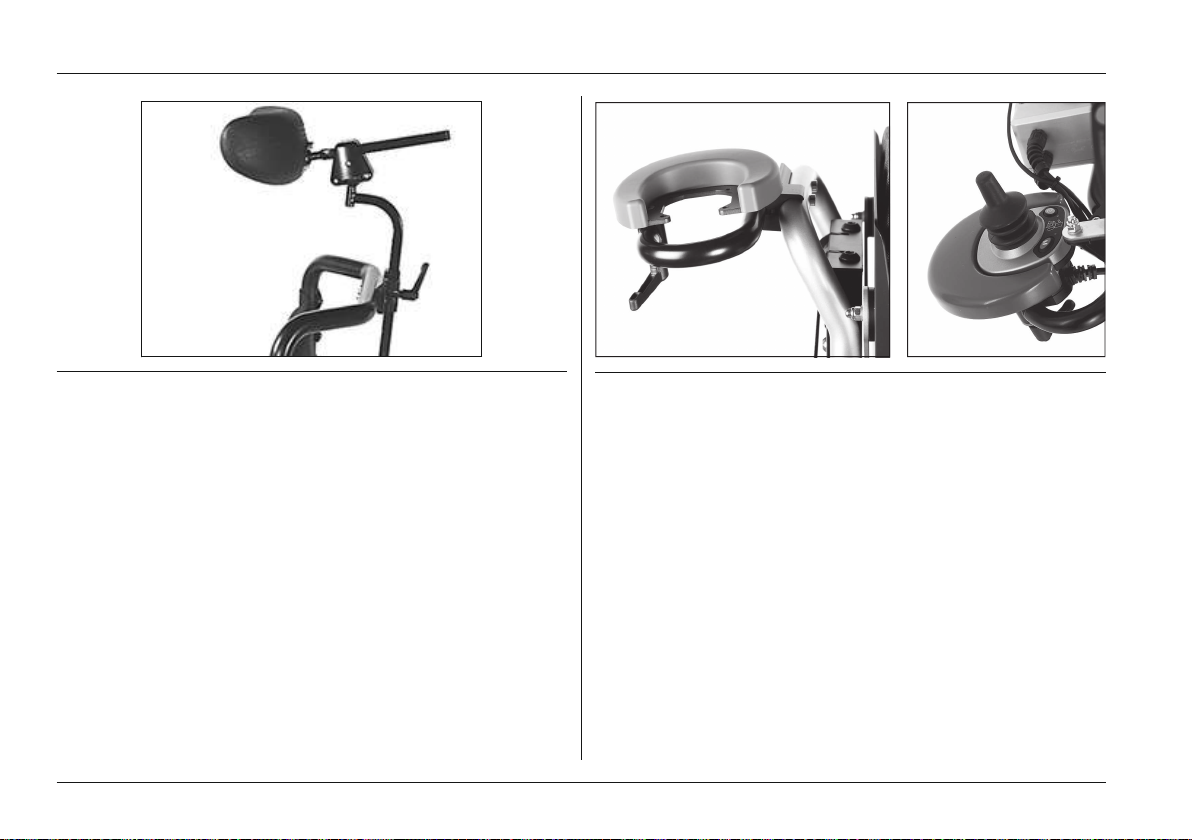
Usage
Fig. 31 Headrest with mounting kit
6.11 Control unit accessories
The power wheelchair can be equipped with the following
optional control unit accessories.
6.11.1 Attendant control
The power wheelchair can be equipped with an optional
Fig. 32 Attaching the attendant control
Functional overview
The attendant uses the attendant control to operate the driv
ing function and the power seat functions.
The module is connected in conjunction with the control
panel or as a separate input device.
separate control panel for attendant operation. The separate
control panel is height-adjustable and removable.
For the standard and contour seats, the attendant control is
located on the backrest cross tube. For the Recaro® seat,
the attendant control is located on the headrest.
52 | Ottobock B500 classic/advanced
Page 53
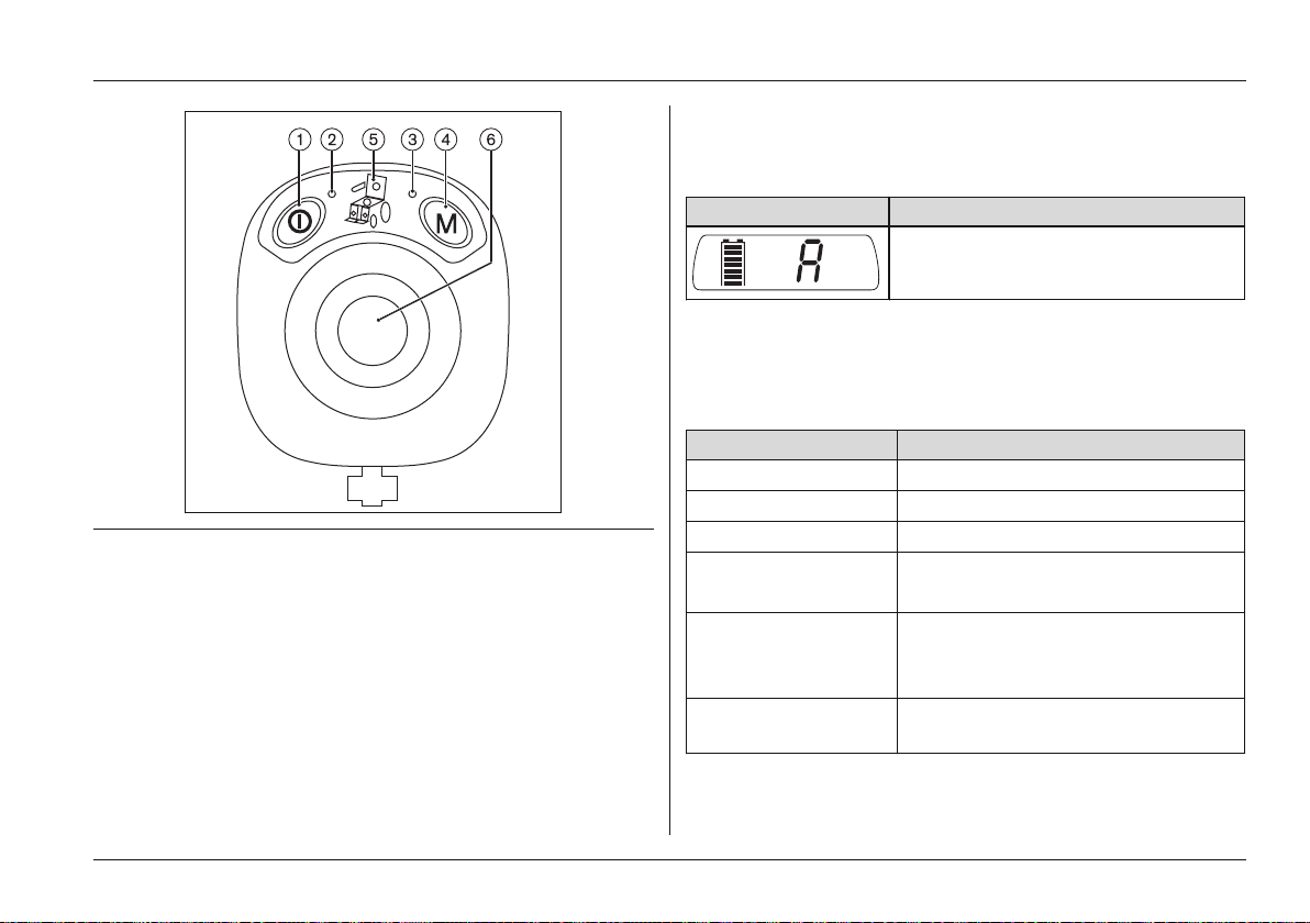
Fig. 33 Attendant control
1 [On/Off] button 4 [Mode] button
2 Battery capacity (LED indic
ator)
3 Mode (LED indicator) 6 Joystick
5 Selected power seat func
tion (LED indicator)
[On/Off] Button
The button is used for switching the power wheelchair on,
activating the drive-away lock and switching the wheelchair
off.
Usage
After the attendant control has been switched on, the LCD
monitor on the control panel shows the following informa
tion:
Display Information
Attendant control activated
Battery Capacity (LED indicator)
The LED lights up when the unit is on.
Colour and flash codes provide information on the current
battery capacity:
LED Information
Green is lit Battery capacity > 70%
Orange is lit Battery capacity 30%–70%
Red is lit Battery capacity < 30%
Red is flashing Battery deep discharge
Charge as soon as possible
Green is flashing Battery over-voltage (e.g. after driv
ing downhill)
Continue driving slowly
Red/Orange/Green
Charging process/Drive-away lock
flashing alternately
Ottobock | 53B500 classic/advanced
Page 54
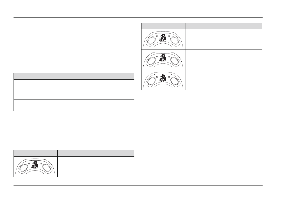
Usage
[Mode] Button
Switch between speed level 1 and 2 by pressing the button
briefly.
Push and hold the button (at least 2 seconds) to switch the
control unit to the power seat functions.
Mode (LED indicator)
The LED has 3 colour and various flash codes to indicate
the statuses of the speed level and system faults:
LED Information
Green is lit Speed level 1
Orange is lit Speed level 2
Red is flashing Fault (see Page79)
Off LED indicator switched to
seat function
Selected Power Seat Function (LED indicator)
The electric seat functions are accessed by pressing and
holding the "M" button (approx. 2 seconds).
The currently selected seat function is indicated on the con
trol panel display (see Page39 ff.) and by the following
LEDs on the attendant control:
Display Information
Power back angle adjustment
Display Information
Power seat tilt
Power seat height adjustment
Coupled power seat adjustment
(backrest and seat tilt)
Moving the joystick to the right switches between the differ
ent seat functions. The respective function can be extended
or retracted by moving the joystick forward or back (see
Page39 et. seq.).
The corresponding LEDs flash if an error occurs (see
Page79).
Joystick
The joystick is used for driving. The further it is moved away
from the centre position, the faster the power wheelchair will
drive in this direction.
If the seat functions are accessed with the [Mode] button,
then the joystick is used to select and activate the seat func
tions (see Page39 ff.).
54 | Ottobock B500 classic/advanced
Page 55
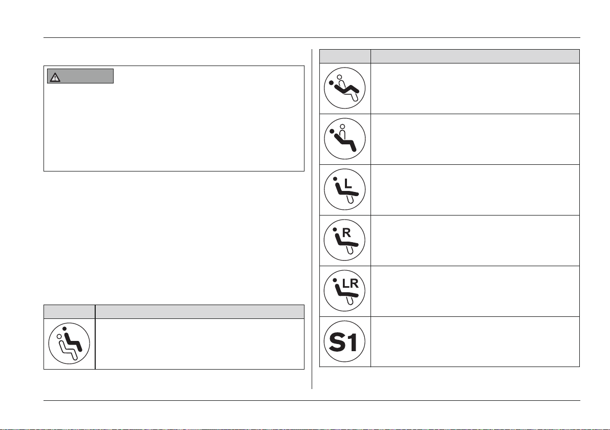
Usage
6.11.2 Push-button module
WARNING
Risk of uncontrolled driving behaviour
Risk of falling, tipping, collision with persons or nearby
objects
► Note that no changes of any kind may be made to the
push-button module by the user. Programming of the
push-button module may only be performed by trained,
authorised personnel.
Power wheelchairs with enAble50 control units can be
equipped with optional push-button modules.
The push-button module lets the user select additional
power seat functions directly during normal driving opera
tion.
Available functions
Depending on the power wheelchair model and program
ming of the push-button module, up to five power seat func
tions (see Fig.34, item 1) can be controlled during normal
driving operation:
Display Information
Power seat height adjustment
Display Information
Power seat tilt
Power back angle adjustment
Power footrest, left
Power footrest, right
Power footrests, coupled
Other special functions (combinations)
S1 – S5
Ottobock | 55B500 classic/advanced
Page 56
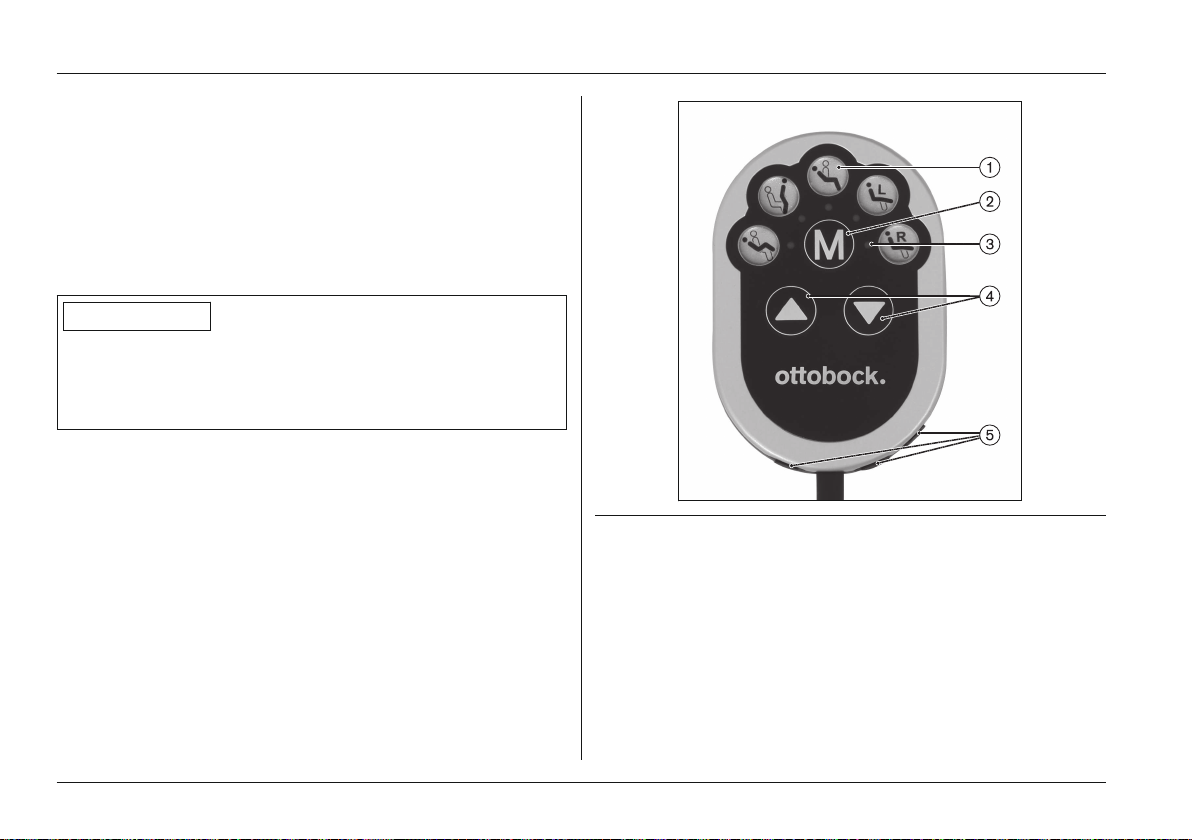
Usage
Key functions
• The [Mode] button (see Fig.34, item 2) is used to
toggle among the different functions (1-2-3-4-5-1-2-…).
• The blue LED (see Fig.34, item 3) indicates the selec
ted power function.
• The respective function (function up/down) is activated
using the buttons [Selected function up] and [Selected
function down] (see Fig.34, item 4).
INFORMATION
The function of the [Selected function up/down] buttons
can be programmed according to the user's wishes (but
ton [Selected function up] = function up or function down depending on programming).
In addition, there are three Piko buttons that can be connec
ted to the push-button module and positioned at will (see
Page57).
The Piko buttons perform the same functions as the [Mode]
button and the [Selected function up]/[Selected function
down] buttons (see Fig.34, items 2 and 4). Symbols on the
back of the push-button module indicate the corresponding
functions.
Fig. 34 Push-button module
1 Available power functions
2 [Mode] button
3 Selected function (LED indicator)
4 [Selected function up/down] buttons (see information box)
5 Jack plugs for connecting Piko buttons
56 | Ottobock B500 classic/advanced
Page 57
6.11.3 Adapter cable for Piko button
INFORMATION
For additional information on the user-specific adjustment
of this function: see inside front cover.
Power wheelchairs with enAble50 control units can be
equipped with optional two-way adapter cables.
• The connected Piko button can be used to control
power seat functions as well as other functions (see
inside front cover). These functions are specified when
the power wheelchair is ordered.
• Each Piko button switch is programmed with a so-called
toggle function. The selected function is activated as
long as the button is pressed. The selected function is
activated in the opposite direction if the button is
released and pushed again.
• For example, if the power back angle adjustment is
activated, the backrest tilts back as long as the button is
pressed the first time around. Activating this function
again causes the backrest to tilt forward as long as the
button is pressed.
6.11.4 External odometer
The power wheelchair can be equipped with an external
odometer.
It is connected to the control panel guard.
Additional information on using it can be found in the manu
facturer's instructions for use.
Usage
Fig. 35 External odometer
6.12 Additional options
6.12.1 Control panel holder
Swing-away control panel holder
The manufacturer offers the option of equipping the power
wheelchair with a removable control panel mounted on a
swing-away control panel holder. This control panel holder
makes it possible to drive the power wheelchair under a
table or closer to an object.
The control panel holder can be rotated up to the armrest.
1) Apply slight pressure to push the control panel holder to
the side.
→ The pivot element is unlocked.
Ottobock | 57B500 classic/advanced
Page 58
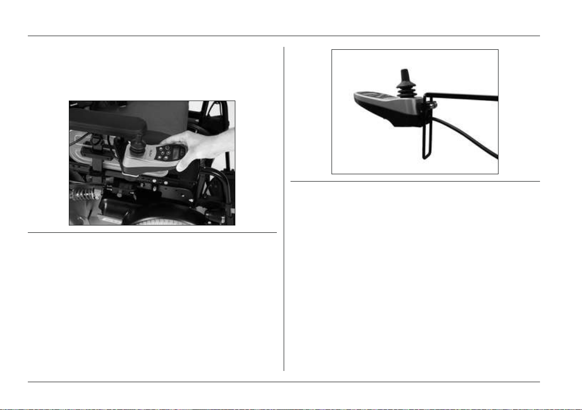
Usage
2) Swing the control panel holder away to the side.
INFORMATION: The pivot element locks in place
again when the holder is rotated back to the origin
al position.
Fig. 36 Swing-away control panel holder with removable con
trol panel
Height-adjustable control panel holder
The power wheelchair can be equipped with a special con
trol panel holder which allows for height adjustment of the
control panel.
1) Loosen the mounting screws.
2) Adjust the height of the control panel holder.
3) Tighten the mounting screw.
Fig. 37 Height-adjustable control panel holder
6.12.2 Lights
The power wheelchair can be equipped with a light kit.
The warning flashers, the right and left direction indicators
and the light are operated via the control panel.
The light kit consists of two rear lights with integrated direc
tion indicators and two front lights, each consisting of a front
LED light and a direction indicator.
The front lights are fastened to the self-contacting side pan
els (see Fig.38, left). When the side panels are inserted
into the side panel holders the contacts touch each other
and current can flow (see Fig.38, right).
To replace broken lamps: see Page74.
58 | Ottobock B500 classic/advanced
Page 59
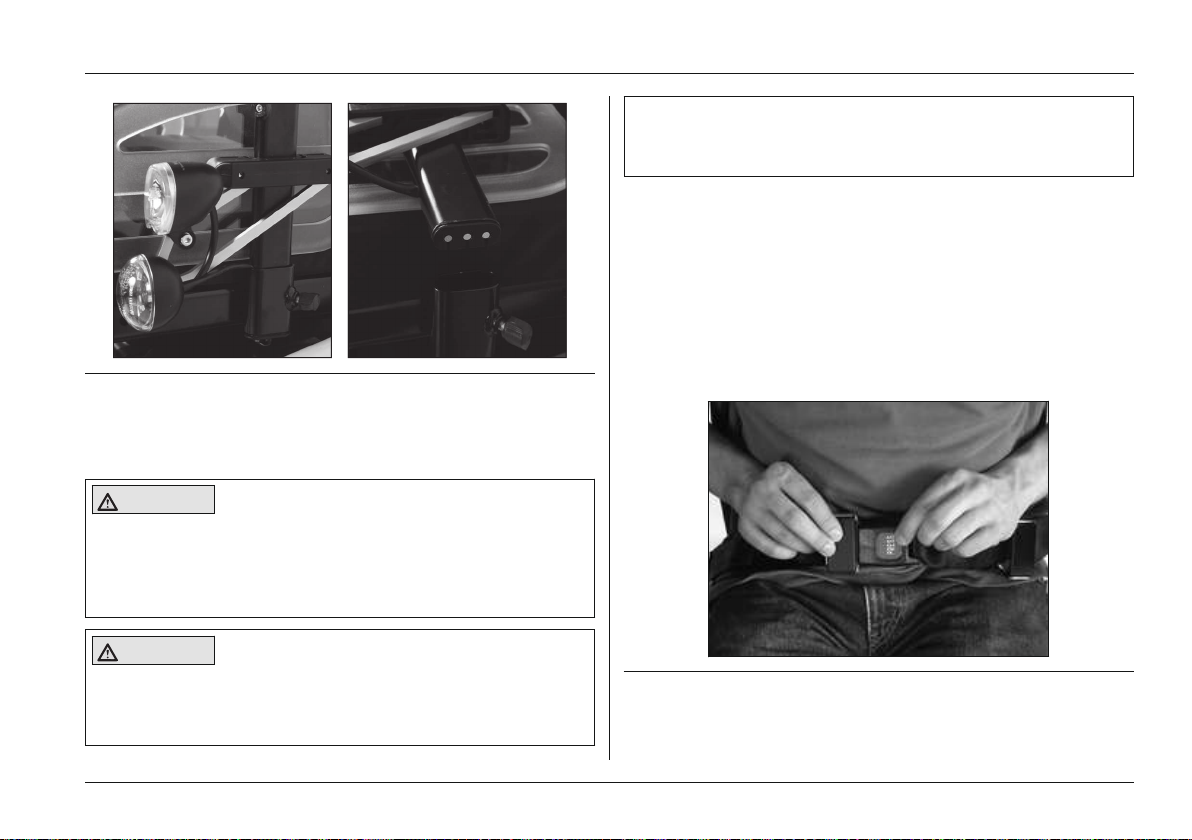
Fig. 38 Front lights
6.12.3 Belts / belt systems
Lap belt
CAUTION
Insufficient support of the seated person
Risk of falling out of the power wheelchair
► Always wear the safety belt / lap belt when driving in
public.
Usage
► Ensure that the lap belt is not too tight against the
body.
► Remove objects or clothing which get caught.
The lap belt provides additional support and keeps the user
from sliding out of the seat.
Putting the lap belt on
> The user sits upright or lies in the power wheelchair.
1) Push the 2 halves together until the buckle engages with
an audible click.
2) Pull to check that it is secure.
→ The belt is put on.
CAUTION
Putting the lap belt on incorrectly
Risk of pressure points, constriction
► Ensure that the buckle lies in the middle of the body.
Fig. 39 Putting the lap belt on
Ottobock | 59B500 classic/advanced
Page 60
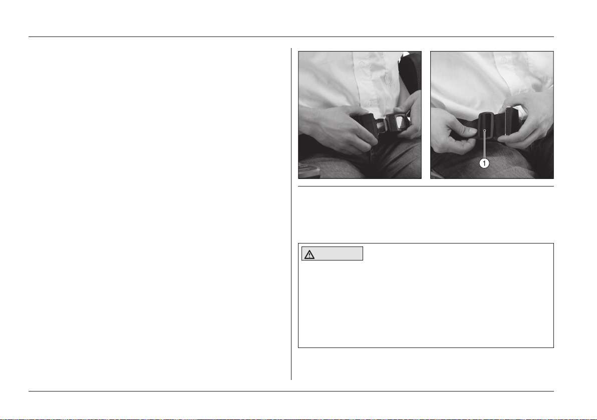
Usage
Opening the lap belt
► Press the red release button.
→ The buckle is open and the belt can be removed.
Adjusting the belt length
The belt length can be adjusted on both sides. Excess belt
length is taken up by the plastic slider.
> The user sits upright or lies in the power wheelchair.
1) Close the belt.
2) Position the 2 buckle halves in the middle of the body.
3) Position the respective half of the buckle at a right angle
(see Fig.40, item 1).
4) Slide the 2 halves of the closure to the desired position.
5) Release the respective half of the buckle.
→ The belt length is adjusted.
Fig. 40 Adjusting the lap belt
1 Belt buckle
Four-point belt/chest belt
CAUTION
Insufficient support of the seated person
Risk of falling out of the power wheelchair
► When driving in public areas, always wear the four-
point or chest belt for additional support.
► Under no circumstances may the belt system be used
as part of a restraint system for transportation in a
wheelchair accessible vehicle.
60 | Ottobock B500 classic/advanced
Page 61
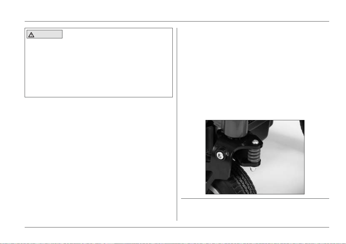
Usage
CAUTION
Putting the four point belt on incorrectly
Risk of pressure points, constriction
► Ensure that the bottom belt is not too tight between the
lap belt and the thigh.
► Ensure that the buckle lies in the middle of the body.
► Ensure that the shoulder belt lies against the chest
equally on both sides and is not too tight.
► Remove objects or clothing which get caught.
The power wheelchair may be equipped with a four-point or
chest belt.
The four-point or chest belt makes it possible to secure
patients in the power wheelchair.
Putting the four-point/chest belt on
> The user sits upright or lies in the power wheelchair.
1) Close all buckles so that they engage with an audible
click.
2) Pull to check that it is secure.
→ The belt is put on.
Adjusting the belt length
> The user sits upright or lies in the power wheelchair.
1) Close the belt.
2) To lengthen: Turn the length adjustment buckle by 90°
and pull.
3) Turn the buckle back to the original position when the
belt length is correct.
4) To shorten: Pull on the free belt end.
→ The belt length is adjusted.
6.12.4 Suspension (steering casters/drive wheels)
The power wheelchair can be equipped with a suspension
system.
A spring and shock absorber element on each of the two
steering casters increases driver comfort, especially on
uneven surfaces, and improves traction.
The suspension effect is improved even more by a drive
wheel suspension.
Fig. 41 Steering caster suspension
Ottobock | 61B500 classic/advanced
Page 62
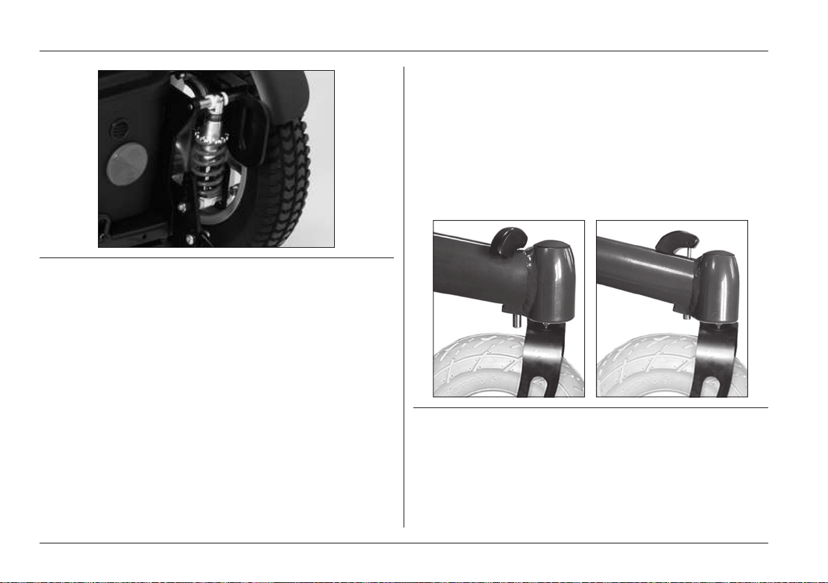
Usage
Fig. 42 Drive wheel suspension
6.12.5 Locking the steering casters
The power wheelchair may be equipped with a steering
caster lock.
These serve to lock the steering casters in the forward direc
tion, so that turning is no longer possible. Having the power
wheelchair drive in a perfectly straight line increases safety
when driving on ramps or using elevators.
→ The steering casters are locked. The power wheelchair
drives straight in both forward and reverse.
Disengaging the steering caster lock
► Turn the folding lever to the middle position until it
engages.
→ The lever is in the unlocked position (see Fig.43, right).
→ The steering casters are unlocked and can swivel freely
again.
Engaging the steering caster lock
Fig. 43 Steering caster lock, engaged and disengaged
► Push the folding lever on the front of the frame to the
side a bit until it disengages from the centre position.
→ The bolt at the bottom edge of the front frame extends
and engages with the front fork as soon as the power
wheelchair faces straight ahead (see Fig.43, left).
62 | Ottobock B500 classic/advanced
6.12.6 Rear bumper
The power wheelchair may be equipped with a bumper.
The bumper provides increased user protection in case of a
collision.
Page 63
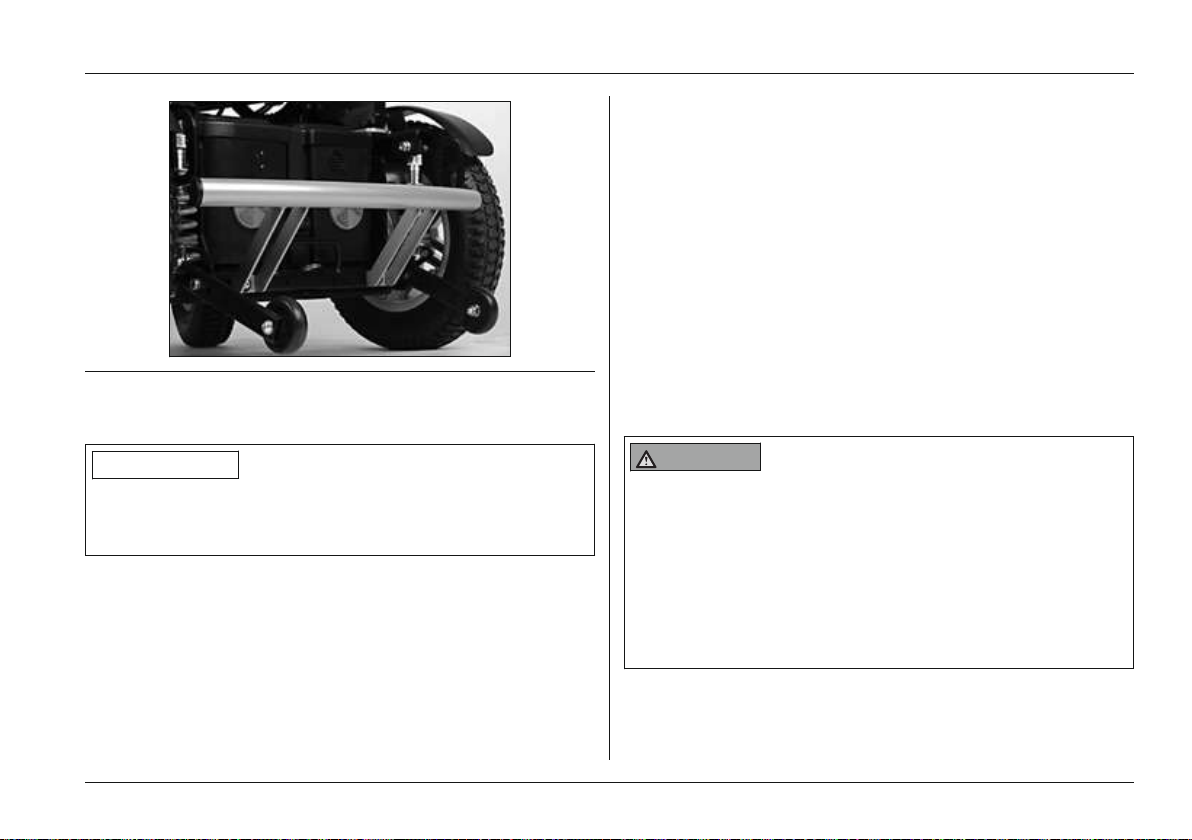
Usage
• Armrest accessories: Special adapters for the armrests
in our accessories catalogue
• Joystick accessories: Tetra fork; STICK S80; softball;
golfball, flexible joystick stem
• Control panel guard: Metal guard for impact protection
• Crutch holder
• Folding rearview mirror
• Tray
• Attachable desktop
• Accessory box, backpack, mobile phone pocket
Fig. 44 Rear bumper
6.12.7 Overview of additional options
INFORMATION
You can find these and other optional add-on components
on the order form and in the wheelchair accessories cata
logue.
The power wheelchair may be equipped with additional
options:
• Curb climbing assist: To overcome curbs and steps with
a maximum height of 100 mm
• Puncture-proof tyres: Solid rubber tyres
• Seating shell adapter: To attach special seating shells;
control panel holder for seating shells also available
6.13 Disassembly/transport
6.13.1 Safety Instructions
WARNING
Lifting the power wheelchair incorrectly
Risk of falling, tipping, damage to the power wheelchair
► Only use sufficiently large hoisting devices to transport
the power wheelchair (see the "Technical Data"
chapter for the weight of the power wheelchair).
► Attendants may only lift the power wheelchair by solidly
attached components. Footrests or armrests may not
be used as lifting points.
Ottobock | 63B500 classic/advanced
Page 64
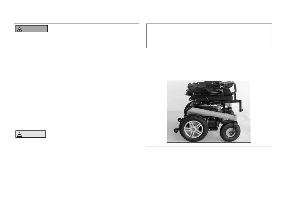
Usage
WARNING
Improper transportation in aircraft
Burns, explosion or damage to the battery due to failure to
observe the rules for transportation
► Follow the IATA (International Air Transport Associ
ation) rules when transporting the power wheelchair in
an aircraft. To this end, the fuse must always be
removed and the battery connectors must be insulated
so that they are short-circuit-proof prior to check-in of
the power wheelchair as luggage.
► Note that those batteries in particular which may leak
or will not be transported upright must be removed and
packaged so they cannot leak or short circuit.
► For more information please visit the www.iata.org
website. The manufacturer recommends contacting the
airline directly before every flight to obtain information
regarding special transport regulations.
CAUTION
Securing the power wheelchair insufficiently during
transport
Risk of pinching, crushing, blows to body parts
► During transportation in vehicles, on lifting platforms or
in lifts, turn the control unit of the power wheelchair off
and lock the brake.
► The power wheelchair must be secured in accordance
with the regulations for the transport device.
► During transport in another vehicle, the power wheel
chair must be secured sufficiently with cargo straps.
Only attach the cargo straps to the corresponding
transportation eyelets and specified tie-down points.
6.13.2 Reducing the transportation size
1) Flip the footrests up and remove.
2) Remove the side panels.
3) Fold the backrest forward on to the seat surface.
Fig. 45 Power wheelchair with reduced transportation size
Folding down the backrest without back angle
adjustment
1) Pull on the backrest release strap.
2) Remove the side panels.
3) Pull the release strap back.
64 | Ottobock B500 classic/advanced
Page 65
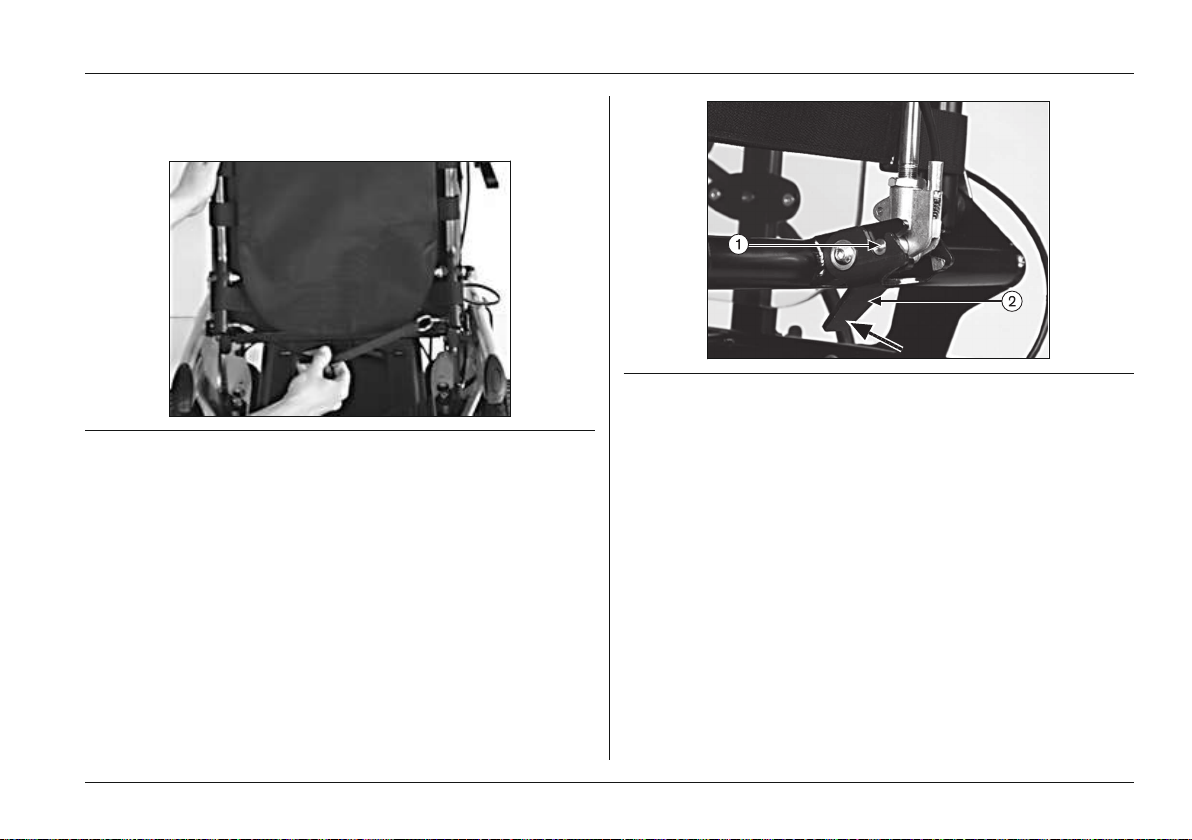
4) Manually fold the backrest forward on to the seat sur
face.
Fig. 46 Folding the backrest down
Folding down the backrest with back angle adjustment
1) Remove the side panels.
2) Push the lever (see Fig.47, item 2) on the back of the
backrest up and unlock the cross bolt (see Fig.47, item
1) at the bottom end of the gas compression spring or
adjustment drive.
3) Remove the cross bolt from the bracket.
4) Fold the backrest forward on to the seat surface.
Usage
Fig. 47 Removing the cross bolt
1 Cross bolt 2 Lever
6.13.3 Reducing the transportation size – Recaro® seat
To remove/install the Recaro® seat on the mobility base and
to fold the backrest down: see Page49.
6.13.4 Preparing for transport
1) Position the power wheelchair in its transport location.
2) Turn the control unit off.
3) Engage the brake.
4) Use the eyebolts and cargo straps to attach the power
wheelchair to the means of transportation.
Ottobock | 65B500 classic/advanced
Page 66
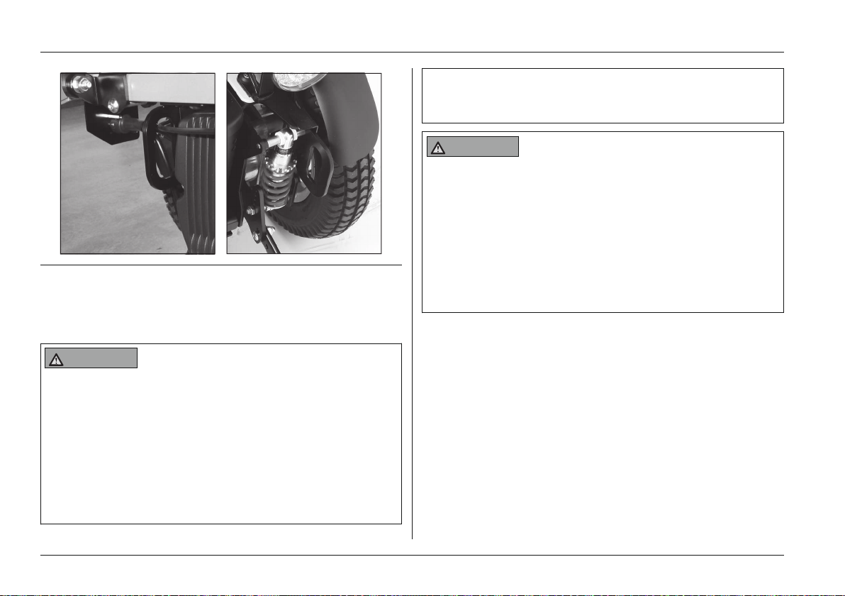
Usage
Fig. 48 Front (left) and rear (right) eyebolts
6.14 Use in a wheelchair accessible vehicle
► Use the power wheelchair in a wheelchair accessible
vehicle only if the seat is all the way down and the
backrest is in a vertical position.
WARNING
Use of the belt system as a restraint system in a
wheelchair accessible vehicle is forbidden
Risk of falling out of the power wheelchair, severe injury in
case of accident
► Under no circumstances may the belt system be used
as part of a restraint system for transportation in a
wheelchair accessible vehicle.
► Note that the belt system is only intended to help sup
port the user sitting in the power wheelchair.
6.14.1 Safety Instructions
WARNING
Use as a seat in a wheelchair accessible vehicle
Risk of falling out of the power wheelchair, severe injury in
case of accident
► Always use the seats and restraint systems in the
wheelchair accessible vehicle first. This is the only way
to provide optimal protection for the occupants in case
6.14.2 Permitted use
The power wheelchair may be used for transport in a wheel
chair accessible vehicle if a suitable restraint system is
used. The securing components (such as lap belts) sold by
the manufacturer only serve as additional restraints for the
person sitting in the power wheelchair.
For more information, please refer to our brochure on using
Ottobock products in wheelchair accessible vehicles, order
number 646D158.
of accident.
► Never transport more than one person in the power
wheelchair.
66 | Ottobock B500 classic/advanced
Page 67

Usage
6.14.3 Restrictions for Use
WARNING
Unallowable use as a seat in a wheelchair accessible
vehicle
Serious injuries due to use with unapproved accessory
combinations
► The power wheelchair cannot be used as a seat in a
wheelchair accessible vehicle with all equipment and
accessory combinations. Observe the restrictions
described below.
Use in a wheelchair accessible vehicle is not permissible if
the following options are used:
• Mechanical or power seat tilt 20°
• Recaro® n-Joy, Recaro® n-Joy-Plus or modular Recaro®
seat system
• Combination of the following:
– Standard seat, large, and seat height 45 cm
– Contour seat, large, and seat height 52 cm
6.14.4 Necessary accessories
An anchor kit is required to use the power wheelchair as a
seat in a wheelchair accessible vehicle. The qualified per
sonnel who fit the wheelchair can provide more information.
The weight of the person being transported is limited to
max. 100 kg in a wheelchair accessible vehicle.
6.14.5 Use
Ensure that the wheelchair is fully secured with lashing
straps for transport in a wheelchair accessible vehicle. For
more information please refer to our brochure on using
Ottobock products in wheelchair accessible vehicles, order
number 646D158.
Straps can be attached via the eyebolts on the frame (see
section 'Necessary accessories').
Before transporting the power wheelchair switch off the con
trol unit and engage the brake.
6.15 Care
6.15.1 Safety Instructions
NOTICE
Incorrect cleaning
Risk of damage to the product, especially to the electronics
► Water must not come into direct contact with the elec
tronics, motor or battery under any circumstances.
► Never use a water jet or high-pressure cleaning appar
atus to clean the product.
► Use a cloth or sponge for cleaning.
► To avoid corrosion, don't use any aggressive cleaning
agents or solvents.
► Check the driving behaviour of the product after clean
ing it.
Ottobock | 67B500 classic/advanced
Page 68
Maintenance/Repair
INFORMATION
Piston rods do not require lubrication. They are mainten
ance-free.
6.15.2 Cleaning
The power wheelchair must be cleaned regularly, depend
ing on the amount of use and the degree of soiling.
• Clean the control panel, battery charger, armrest and
trim components with a damp cloth and mild cleaning
solution.
• Use a dry brush to clean the seat and back upholstery
as well as the seat cushion.
• Use a damp plastic brush to clean the wheels and
frame.
6.15.3 Disinfection
► Wipe all parts of the product with a disinfectant.
Important information about disinfecting
• Water-based disinfectants should be used. Observe the
instructions for use provided by the manufacturer.
• Prior to disinfection, clean the seat and back upholstery,
seat cushion, control panel and armrests.
7 Maintenance/Repair
7.1 Safety Instructions
WARNING
Improper maintenance, repairs or adjustments
User injuries, damage to the product due to failure to
observe maintenance intervals
► The power wheelchair may only be serviced by quali
fied personnel trained by the manufacturer. The func
tionality and operating safety of the power wheelchair
must be verified and service performed at least 1 x per
year.
► In case of frequent user changes (children and grow
ing youth) or changing clinical pictures, the power
wheelchair should be inspected, adjusted and serviced
1 x every six months.
► Repairs and adjustments to the brake may only be
made by qualified personnel trained by the manufac
turer. Incorrect settings can lead to a loss of braking
power.
NOTICE
Failure to inspect important product features
Damage to the product
68 | Ottobock B500 classic/advanced
Page 69

► Inspect the seat adjustment features for visible signs of
damage at least 1 x per month and ensure all screw
connections are tight.
► Maintain sufficient air pressure in the tyres. The correct
tyre pressure is printed on the tyre casing and listed in
the section "Technical Data".
7.2 Maintenance
For the components, special attention must be paid to the
following points in the maintenance table below:
• Functionality of the components
• Correct adjustment of the components
• Damage, deformation
• Tightness of screw connections
Maintenance/Repair
Ottobock | 69B500 classic/advanced
Page 70

Maintenance/Repair
7.2.1 Maintenance intervals
The functions described below must be checked by the user or an attendant at the specified intervals:
Component Task Prior to
Weekly Monthly
every use
Rear wheels
Check whether wheel mounts are securely fastened X
Check whether the central nut on the drive shaft is securely
fastened
Check whether wheels rotate freely and without axial runout X
Check directional stability of the power wheelchair X
Caster wheels
Check whether the fork fits in the adapter without play X
Check whether wheels rotate freely and without axial runout X
Check whether the mounting nuts are tight X
Check whether mounting screws are fastened properly XSeat attachment
Recaro® seat: Check whether seat lock is positioned
X
securely
Check ratchet mechanism for functionality and firm fit XFootrest
Check for damage to footrests X
Manual elevating
footrest
Check ratchet mechanism for functionality and firm fit X
Check for damage to footrests X
Visually inspect the piston rod for scratches and oil leaks X
Padding/belts
Ensure padding is in perfect condition X
Check the safety belts for wear X
Check belt buckle for functionality X
Tyres Check air pressure (see tyre sidewall) X
X
70 | Ottobock B500 classic/advanced
Page 71

Maintenance/Repair
Component Task Prior to
every use
Check for sufficient tread depth (min. 1 mm) XTyres
Check for damage X
Batteries Check battery charge level X
Check for external damage XLights
Verify functionality X
Electronics
Check whether the control unit is functioning properly
X
(inform qualified personnel of any LED error messages)
Check whether the battery charger is functioning properly
(inform qualified personnel of any LED error messages)
Check plug connections X
When brake is disengaged: check whether the LED indicat
XBrake
or on the control panel is flashing
When brake is engaged: check braking function by trying to
push the chair
Visually inspect all moving components and cabling for dam
ments
age
Check whether screw connections are tight X
Side panel and arm
rest
Check whether mounting screws are fastened properly X
Check whether screw connections between the armrest and
X
the control unit are tight
Check armrest for damage X
Gas compression
Visually inspect the piston rod for scratches and oil leaks X
spring or actuator
Weekly Monthly
X
X
XPower seat adjust
Ottobock | 71B500 classic/advanced
Page 72
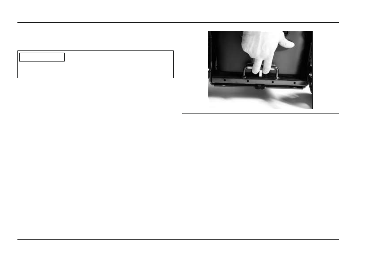
Maintenance/Repair
7.3 Repair
7.3.1 Replacing a defective fuse
INFORMATION
When replacing, only use fuses of the same type. Note the
rating printed on it.Note the rating printed on it.
The safety fuse (for values, see section "Technical data" >
table "Electrical system") is located in the battery drawer
(power wheelchair with drive wheel suspension) or in a bat
tery tray (power wheelchair without drive wheel suspension).
Opening the battery drawer (in models with drive wheel
suspension)
> The control unit is turned off.
1) Pull up the release bolt.
2) Pull gently on the battery drawer to roll it out to the rear.
3) Open the clip on the strap.
4) Remove the battery drawer cover.
Fig. 49 Pulling on the release bolt
Opening the battery tray (on models without drive
wheel suspension)
> The control unit is turned off.
1) Lift the seat cushion from the seat plate.
2) Remove the seat bottom.
3) Open the clip on the battery tray strap.
4) Remove the battery tray cover.
72 | Ottobock B500 classic/advanced
Page 73
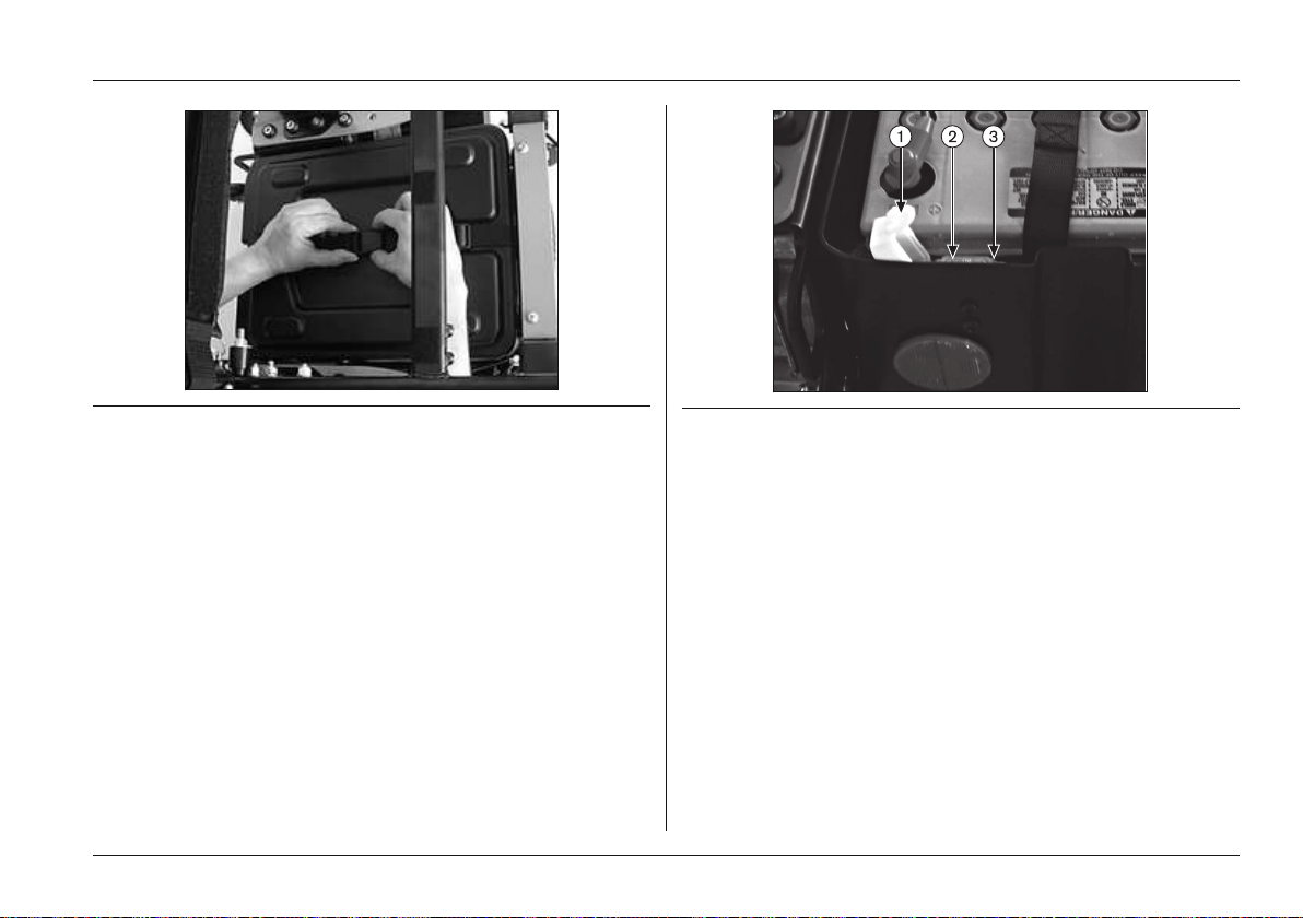
Maintenance/Repair
Fig. 50 Unbuckling the strap
Removing the fuse
1) Open the fuse holder cover (see Fig.51, item 1).
2) Pull the fuse out of the spring contacts (see Fig.51,
item 2).
Installing the fuse
1) Remove the fuse from the protective cover.
2) Open the fuse holder cover.
3) Centre the fuse on the spring contacts and insert it.
4) Close the fuse holder cover until you feel it engage.
Fig. 51 Fuse in the fuse housing
1 Fuse housing with cover
2 Fuse inserted
3 Fuse holder
Closing the battery drawer (in models with drive wheel
suspension)
1) Place the cover on the battery drawer.
2) Close the strap buckle.
3) Push the drawer under the seat until the release bolt
engages.
INFORMATION: As you close the battery drawer,
ensure that the release bolt engages correctly in
the intended notch.
Ottobock | 73B500 classic/advanced
Page 74
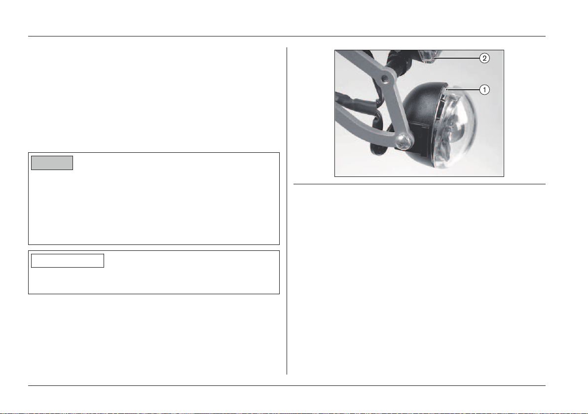
Maintenance/Repair
Closing the battery tray (on models without drive wheel
suspension)
1) Place the cover on the battery tray.
2) Close the strap buckle.
3) Replace the seat bottom and push it down tightly.
4) Press the seat cushion firmly onto the hook-and-loop
material on the seat plate.
7.3.2 Replacing a defective bulb
NOTICE
Penetration of moisture
Risk of damage to the light
► During installation, ensure that the plates are seated
accurately in the housing.
► Ensure that the screws are seated tightly against the
plate.
INFORMATION
Lamp housings and lamps can both be ordered from the
specialist dealer.
Fig. 52 Front lights
1 Notch (place screwdriver here)
2 Front LED light
Replacing the front direction indicator lamp
> Remove the fuse (see previous section).
1) Place a small screwdriver into the notch in the direction
indicator housing and flip the cover down (see Fig.52,
item 1).
2) Remove the cover.
3) Turn the defective bulb slightly to unlock it and then
remove it.
4) Grasp the new bulb with a cloth, insert it into the socket
and lock it in place.
5) Position the cover, hook it on and press it down tightly.
74 | Ottobock B500 classic/advanced
Page 75
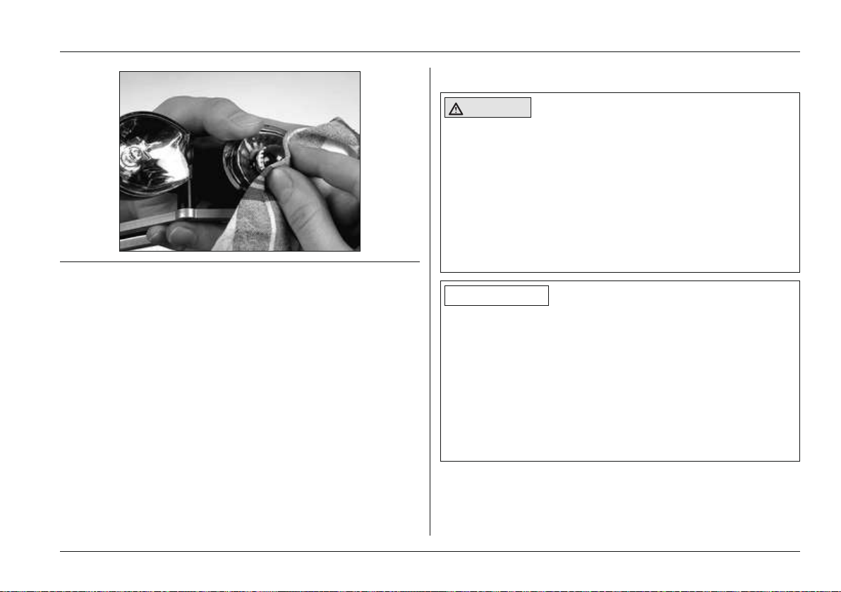
Fig. 53 Replacing the front direction indicator bulb
Maintenance/Repair
7.4 Troubleshooting
CAUTION
Risk of uncontrolled driving behaviour
Risk of falling, tipping, collision with persons or nearby
objects
► If any faults, defects or other hazards that can lead to
personal injury are detected, the product must be
taken out of service immediately.
► Contact your authorised specialist dealer if uncon
trolled movement of the product occurs due to a mal
function.
Replacing the front LED light
The front LED light (see Fig.52, item 2) is maintenancefree. If repairs are required, the qualified personnel who fit
ted the wheelchair can help.
Replacing the rear LED light (including rear direction
indicator)
The rear LED light is maintenance-free. If repairs are
required, the qualified personnel who fitted the wheelchair
can help.
7.3.3 Replacing the battery
Batteries may only be replaced by authorised personnel.
INFORMATION
In the event of communication problems in the control unit
bus system, the system triggers an emergency stop in
order to prevent any uncontrolled functions.
► Note that after every emergency stop, you have to turn
the power wheelchair control unit on again.
► If the driving function is still not available after turning
the control unit on again, activate pushing mode by
releasing the brake.
► Contact a specialist dealer.
Faults are indicated on the LCD display via the "Battery
Capacity" indicator on the control panel or on the attendant
control (if available). The following table shows the individu
Ottobock | 75B500 classic/advanced
Page 76

Maintenance/Repair
al notifications as well as the associated fault sources and
possible causes and measures.
If the measures described here do not resolve the faults
completely, contact your specialist dealer. The specialist
dealer is able to read the exact error codes with a handheld
programming device and can perform a targeted system
analysis.
The control unit stores a list of all faults that occur. The spe
cialist dealer reads this information, for example during a
general overhaul of the power wheelchair. The specialist
dealer uses the saved data to determine future service and
maintenance intervals.
7.4.1 Types of notifications
Warning
A warning indicates a status or malfunction of one or several
components of the power wheelchair. The function of com
ponents that have no errors is not restricted.
For example, if the connection between the control unit and
seat motor is faulty, this error will only be indicated if the
user attempts to activate the motor. However, the driving
function is still available.
Fault
A fault impairs one or several functions of the power wheel
chair. The power wheelchair and its functions are not fully
operational until the fault is resolved.
76 | Ottobock B500 classic/advanced
Page 77
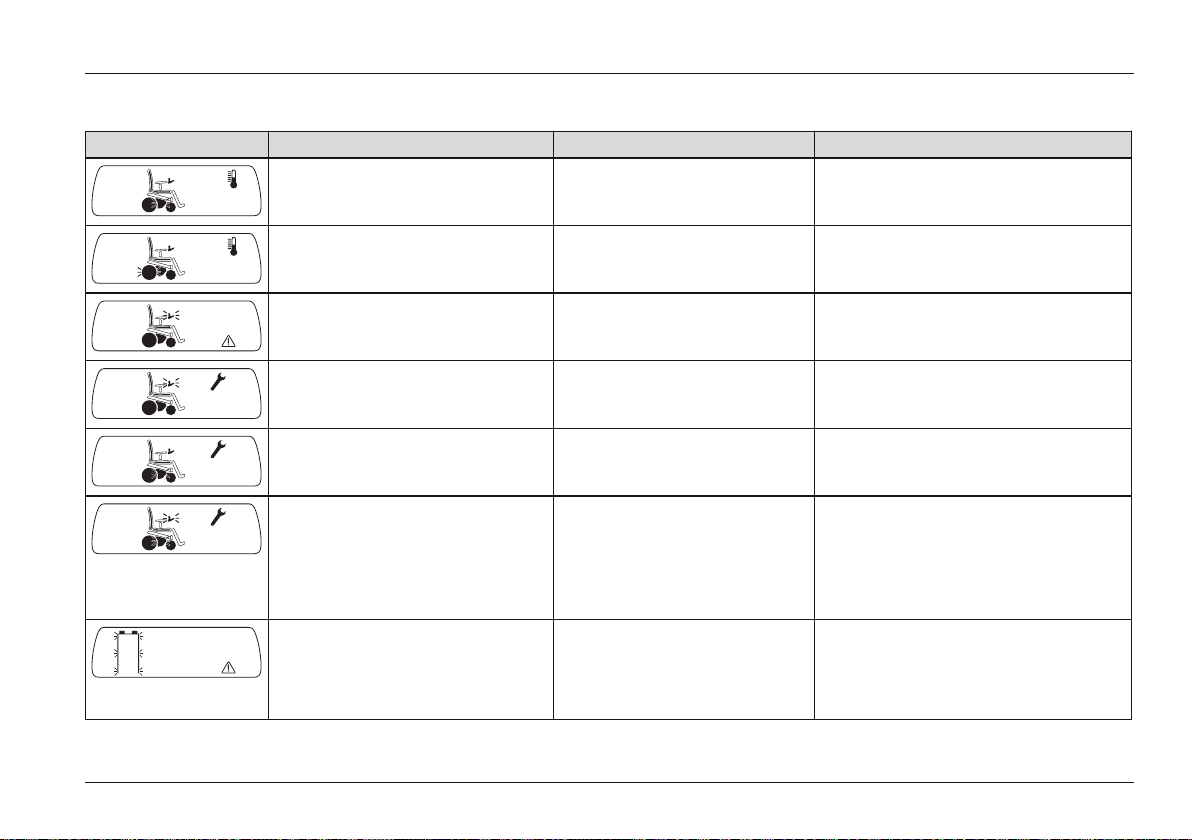
Maintenance/Repair
7.4.2 Wheelchair control unit fault overview
Display Error/Warning Probable cause Possible corrective action
Controller temperature warning Overheating due to excessive
Cool down phase
load
Motor temperature warning Overheating due to excessive
Cool down phase
load
Joystick warning Joystick not in home position
when the unit is turned on
Move the joystick to the home posi
tion before switching the unit on
Hand-held control unit fault Defective joystick Contact specialist dealer
Controller fault Defective controller Check all connections
Contact specialist dealer
Communication error (altern
ately flashing)
Faulty connection between
the hand-held control unit
Check cabling/plug connections
Contact specialist dealer
and the controller;
Defective cabling, software
or hardware
Battery undervoltage Battery deep discharge
Battery cable malfunctioning
or faulty connection to the
battery
Charge as soon as possible
Check the connection to the battery
(charge the battery if the connection
is good)
Ottobock | 77B500 classic/advanced
Page 78
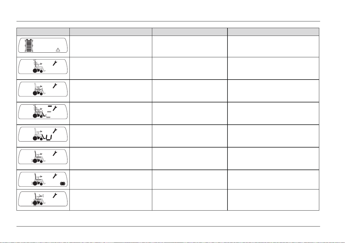
Maintenance/Repair
Display Error/Warning Probable cause Possible corrective action
Battery overvoltage Voltage too high (after com
Continue driving slowly
plete charging and driving
downhill)
Back angle adjustment motor
fault
Faulty cabling or plug con
tacts
Check cabling/plug connections
Contact specialist dealer
Defective actuator
Seat tilt motor fault Faulty cabling or plug con
tacts
Check cabling/plug connections
Contact specialist dealer
Defective actuator
Seat height adjustment motor
fault
Faulty cabling or plug con
tacts
Check cabling/plug connections
Contact specialist dealer
Defective actuator
Power footrest motor fault Faulty cabling or plug con
tacts
Check cabling/plug connections
Contact specialist dealer
Defective actuator
Drive motor fault Faulty cabling or plug con
tacts
Check cabling/plug connections
Contact specialist dealer
Defective drive motor
Brake fault Brake disabled
Defective brake
Close brake release
Contact specialist dealer
Emergency stop Severe controller/hand-held
control unit and/or drive
Check cabling/plug connections
Contact specialist dealer
motor malfunction
78 | Ottobock B500 classic/advanced
Page 79

Maintenance/Repair
7.4.3 Attendant control fault overview
Battery LED
LED Fault/Warning Cause Possible corrective action
Red is flashing Battery undervoltage Battery deep discharge Charge as soon as possible
Green is flashing Battery overvoltage Voltage too high (after com
Continue driving slowly
plete charging and driving
downhill)
Mode LED
LED Fault/Warning Cause Possible corrective action
Red is flashing Various product faults More detailed information about the existing fault is shown
on the LCD monitor on the control panel (see Page77 f.).
Seat function LEDs
LED Fault/Warning Cause Possible corrective action
Backrest LED is flashing Back angle adjustment motor
fault
Seat bottom LED is flashing Seat tilt motor fault Faulty cabling or plug con
2 LEDs below the seat bot
tom are flashing
Backrest/seat bottom LED is
flashing
Seat height adjustment motor
fault
Power seat function temper
ature warning
Faulty cabling or plug con
tact
Defective actuator
tact
Defective actuator
Faulty cabling or plug con
tact
Defective actuator
Overheating due to excessive
load
Check cabling/plug connec
tions
Contact specialist dealer
Check cabling/plug connec
tions
Contact specialist dealer
Check cabling/plug connec
tions
Contact specialist dealer
Cool down phase
Ottobock | 79B500 classic/advanced
Page 80

Disposal
8 Disposal
8.1 Safety Instructions
NOTICE
Disposal of batteries
Pollution due to incorrect disposal
► Observe the information printed on the batteries by the
manufacturer.
► Note that the batteries may not be disposed of as
household waste.
8.2 Disposal Information
To dispose of the wheelchair, return it to the specialist deal
er.
Please return defective batteries to your specialist dealer
when buying new ones.
All product components must be disposed of properly in
accordance with national regulations.
9 Legal Information
9.1 Service life
Based on market observations and the current state of tech
nology, the manufacturer has calculated that the product
can be used for a period of 5 years, provided that it is used
properly and that the service and maintenance instructions
are followed. Storage times at the dealer or with paying
parties are not included in this period.
However, we would like to emphasise that the product is
reliable far beyond this defined period of time, provided that
it is cared for and maintained properly.
If the service life is reached, the user or a responsible
attendant should contact the qualified personnel who fitted
the product or the manufacturer's service (see inside or out
side of rear cover for address).
9.2 Liability
The manufacturer’s warranty applies only if the device has
been used under the conditions and for the purpose
described. The manufacturer recommends that the device
be used and maintained according to the instructions for
use.
The manufacturer is not responsible for damages caused by
components and spare parts not approved by the manufac
turer. Repairs must be carried out exclusively by authorised
dealers or by the manufacturer.
9.3 CE Conformity
This device meets the requirements of the 93 / 42 / EEC
guidelines for medical devices. This device has been classi
fied as a class I device according to the classification criter
ia outlined in appendix IX of the guidelines. The declaration
of conformity was therefore created by the manufacturer
with sole responsibility according to appendix VII of the
guidelines.
80 | Ottobock B500 classic/advanced
Page 81

Legal Information
9.4 Warranty terms
More information on the warranty terms and conditions is
available from the qualified personnel who adapted the
product or from the manufacturer's service department (see
back inside cover or back cover for addresses).
9.5 Trademarks
All denotations within this accompanying document are sub
ject to the provisions of the respective applicable trademark
laws and the rights of the respective owners, with no restric
tions.
All brands, trade names or company names may be
registered trademarks and are subject to the rights of the
respective owners.
Should trademarks in this accompanying document fail to be
explicitly identified as such, this does not justify the conclu
sion that the denotation in question is free of third-party
rights.
Ottobock | 81B500 classic/advanced
Page 82
Appendices
10 Appendices
10.1 Technical data
General Information
Application class (according to DIN EN 12184) Class B
Dimensions and weights Standard Seat Contour seat Recaro® seat*
Seat depth 340 – 500 mm 360 – 480 mm 380 – 560 mm
Seat width 340 – 560 mm 380 – 560 mm --Seat height 450mm, 500mm,
550mm
Lower leg length 250 – 540mm 280 – 540mm
* For seat version Recaro® n-joy Plus
Dimensions and weights
Armrest height (telescoping armrest) 225 - 350 mm; standard seat, junior: 205 - 275 mm
Armrest length (standard) 260mm
Back angle -9/1/11/21° or 0/10/20/30°
Overall width 645mm
Overall height 1030mm
Overall length 1080mm
Weight when empty* 95 kg
approx. 520mm, approx. 570mm
82 | Ottobock B500 classic/advanced
Page 83

Appendices
Dimensions and weights
Transport weights* See weight when empty*, of which:
Side panel: < 1kg
Footrest (standard): approx. 1kg
Footrest (manually elevating): 1.8kg
Max. load capacity (user weight)** Basic model: 140kg (with optional 40-cm power seat height adjustment:
130 kg)
Model with standard seat, junior option: 100 kg
Turning radius 900 mm
Turning circle*** 1550 mm
Caster wheel tyre size 9" – 10"
Drive wheel tyre size 14"
Tyre pressure See tyre sidewall
* The specified weights vary according to the selected options and model.
** For further limitations pertaining to maximum load capacity please refer to the order form.
*** = 3-point turn by 180°
Electrical system*
IP protection rating (according to DIN EN
IPX4
60529)
Operating voltage 24V
Batteries:
Gel (standard)
AGM (optional)
2 x 12V; 63Ah(C5)
2 x 12V; 63Ah(C5)
Ottobock | 83B500 classic/advanced
Page 84

Appendices
Electrical system*
Lighting:
Front LED light
Front direction indicator
Rear LED light (including rear direction indic
24V, maintenance-free
10W, 24V
24V, maintenance-free
ator)
Fuse 80 A (for enAble40 control unit)
120 A (for enAble50 control unit)
Battery charger For more information, see the included battery charger instructions for use
* The product meets all requirements under ISO 7176-14.
Control unit
Model
B500 'classic': enAble40
B500 'advanced': enAble50
Operating voltage
Max. output current per motor
24 V DC
75 A (for enAble40 control unit)
130 A (for enAble50 control unit)
Driving data
Speed 6 km/h and/or 10 km/h (see nameplate for precise information)
Maximum safe inclination Climbing ability, basic model*: 9.5° (17%)
Approved climbing ability with lowered seat height adjustment feature/seat
tilt: max. 6° (10%)
Maximum obstacle height 50 mm (100mm with curb climbing assist)
Range (on level surfaces)** approx. 35km
84 | Ottobock B500 classic/advanced
Page 85
Appendices
Driving data
Braking distance (according to DIN EN
12184:2009)***
at 6 km/h: 1000 mm (horizontal); 2000 mm (inclination)
at 10 km/h: 2100 mm (horizontal); 4200 mm (inclination)
Operating temperature -25°C to +50°C
Transport and storage temperature -40°C to +65 °C
* In individual cases, the continuous climbing ability can be significantly lower than the value specified.
** The specified range was determined under defined conditions according to ISO 7176-4. In practice the range can be
reduced by up to 50%. For information on this, see the section "Range" in the instructions for use (user).
*** The braking distance can be correspondingly longer due to user weight, installed options and condition of the tyres, and
due to weather and surface conditions.
Corrosion protection
Corrosion protection Coated frame
Ottobock | 85B500 classic/advanced
Page 86

86 | Ottobock B500 classic/advanced
Page 87

Kundenservice/Customer Service
Europe
OttoBock HealthCare
DeutschlandGmbH
37115 Duderstadt · Germany
T+49(0) 5527848-3433
F+49(0) 5527848-1460
[email protected]
Otto Bock Healthcare
Products GmbH
1070 Wien · Austria
T +43(0) 1 5269548
F +43(0) 1 5267985
[email protected]
Otto Bock Adria Sarajevo D.O.O.
71000 Sarajevo
Bosnia-Herzegovina
T+387(0) 33766200
F+387(0) 33766201
[email protected]
Otto Bock Bulgaria Ltd.
1612 Sofia · Bulgaria
T+359(0) 28057980
F+359(0) 28057982
[email protected]
OttoBock Suisse AG
CH-6036 Dierikon
T+41(0) 414556171
F+41(0) 414556170
[email protected]
Otto Bock ČR s.r.o.
33008 Zruč-Senec
Czech Republic
T+420(0) 377825044
F+420(0) 377825036
[email protected]
Otto Bock Iberica S.A.
28760 Tres Cantos (Madrid)
Spain
T+34(0) 918063000
F+34(0) 918060415
[email protected]
Otto Bock France SNC
91978 Courtaboeuf Cedex
France
T+33(0) 169188830
F+33(0) 169071802
[email protected]
Otto Bock Healthcare plc
Egham, Surrey TW20 0LD
United Kingdom
T +44(0) 1784 744900
F +44(0) 1784 744901
[email protected]
Otto Bock Hungária Kft.
1135 Budapest · Hungary
T+36(0) 14511020
F+36(0) 14511021
[email protected]
Otto Bock Adria d.o.o.
10431 Sveta Nedelja · Croatia
T+385(0) 13361544
F+385(0) 13365986
[email protected]
OttoBock Italia Srl Us
40054 Budrio (BO) · Italy
T+39(0) 051692-4711
F+39(0) 051692-4720
[email protected]
Otto Bock Benelux B.V.
5692 AK Son en Breugel
The Netherlands
T+31(0) 499474585
F+31(0) 499476250
[email protected]
Industria Ortopédica
Otto Bock Unip. Lda.
1050-161 Lisboa · Portugal
T+351(0) 213535587
F+351(0) 213535590
[email protected]
OttoBock Polska Sp. z o. o.
61-029 Poznań · Poland
T+48(0) 616538250
F+48(0) 616538031
[email protected]
OttoBock Romania srl
077405 Chitila, Jud. Ilfov
Romania
T+40(0) 214363110
F+40(0) 214363023
[email protected]
OOO Otto Bock Service
143441 Moscow
Region/Krasnogorskiy Rayon
Russian Federation
T+7(0) 4955648360
F+7(0) 4955648363
[email protected]
OttoBock Scandinavia AB
60114 Norrköping · Sweden
T+46(0) 11280600
F+46(0) 11312005
[email protected]
OttoBock Slovakia s.r.o.
85101 Bratislava 5
Slovak Republic
T+421(0) 232782070
F+421(0) 232782089
[email protected]
OttoBock Sava d.o.o.
34000 Kragujevac
Republika Srbija
T+381(034)351671
F+381(034)351671
[email protected]
OttoBock Ortopedi ve
Rehabilitasyon Tekniği Ltd. Şti.
34387 Mecidiyeköy-İstanbul
Turkey
T+90(0) 2123565040
F+90(0) 2123566688
[email protected]
Africa
Otto Bock Algérie E.U.R.L.
Mackle-Ben Aknoun · Alger
DZ Algérie
T+213(0) 21913863
F+213(0) 21913863
[email protected]
Otto Bock Egypt S.A.E.
Mohandessein - Giza · Egypt
T+202(0) 33024390
F+202(0) 33024380
[email protected]
Otto Bock South Africa (Pty) Ltd
Johannesburg · South Africa
T+27(0) 113121255
[email protected]
Americas
Otto Bock Argentina S.A.
CP 1426 Ciudad Autônoma de
Buenos Aires · Argentina
T+54(0) 114706-2255
F+54(0) 114788-3006
[email protected].
ar
Otto Bock do Brasil Ltda.
13051-030 Campinas-SãoPaulo
Brasil
T+55(0) 1937293500
F+55(0) 1932696061
[email protected]
Otto Bock HealthCare Canada
Burlington, Ontario, L7L 5N5
Canada
T+1(0) 289288-4848
F+1(0) 289288-4837
[email protected]
Otto Bock HealthCare
Andina Ltda.
Bogotá · Colombia
T+57(0) 18619988
F+57(0) 18619977
[email protected]
Otto Bock de Mexico S.A. de C.V.
C.P. 01180 México, D.F. · Mexico
T+52(0) 5555750290
F+52(0) 5555750234
[email protected]
Otto Bock HealthCare
Minneapolis, MN 55447 · USA
T+1(0) 7635539464
F+1(0) 7635196153
usa.customerservice
@ottobockus.com
Asia/Pacific
Otto Bock Australia Pty. Ltd.
Baulkham Hills NSW 2153
Australia
T+61(0) 288182800
F+61(0) 288144500
[email protected]
Beijing Otto Bock
Orthopaedic Industries Co., Ltd.
Beijing, 100015, P.R. China
T+8610(0) 85986880
F+8610(0) 85980040
[email protected]
Otto Bock Asia Pacific Ltd.
Wanchai, Hong Kong · China
T+852(0) 25989772
F+852(0) 25987886
[email protected]
OttoBock HealthCare India
Mumbai, 400071 · India
T+91(0) 2225201268
F+91(0) 2225201267
[email protected]
OttoBock Japan K. K.
Tokyo, 108-0023 · Japan
T+81(0) 33798-2111
F+81(0) 33798-2112
[email protected]
Otto Bock Korea HealthCare Inc.
137-070 Seoul · Korea
T+82(0) 2577-3831
F+82(0) 2577-3828
[email protected]
Otto Bock
South East Asia Co., Ltd.
Bangkok 10900 · Thailand
T+66(0) 29303030
F+66(0) 29303311
[email protected]
Other countries
OttoBock HealthCare GmbH
37115 Duderstadt · Germany
T+49(0) 5527848-1590
F+49(0) 5527848-1676
[email protected]
Page 88

Ihr Fachhändler | Your specialist dealer
Versandanschrift für Rücksendungen/Adress for Returns:
Otto Bock Manufacturing Königsee GmbH
Lindenstraße 13 · 07426 Königsee-Rottenbach/Germany
Otto Bock Mobility Solutions GmbH
Lindenstraße 13 · 07426 Königsee-Rottenbach/Germany
T +49 (0) 69 9999 9393 · F +49 (0) 69 9999 9392
[email protected] · www.ottobock.com
Ottobock has a certified Quality Management System in accordance with ISO 13485.
© Ottobock · 647G742=EN-09-1309
 Loading...