

Page 1
Operating instructions
Pressure Probe OTT PLS
English
Page 2

We reserve the right to make technical changes and improvements without notice.
Page 3

Table of contents
1 Scope of Supply 4
2 Order Numbers 4
3 Basic safety instructions 5
4 Introduction 6
5 Installing the pressure probe 8
5.1 Installation type A: fixing the pressure probe into a protective device 8
5.2 Installation type B: hanging pressure probe 9
5.3 Connecting humidity absorbing system 10
5.4 Wire assignment of the pressure probe cable 10
5.5 Connecting the OTT PLS to any datalogger using an SDI-12 interface 11
5.6 Connecting the OTT PLS to any datalogger using a 4 … 20 mA interface 11
5.7 Determining the maximum load resistance at the 4 … 20 mA interface 11
5.8 Note on using the 4 … 20 mA interface 12
5.9 Note on using the RS-485 interface 12
6 SDI-12 Commands and Responses 13
6.1 Standard commands
6.2 Advanced SDI-12 commands
13
15
7 Carrying out maintenance work 20
8 Searching for disruptions/troubleshooting 21
9 Repair 22
10 Note about the disposal of old units 22
11 Technical Data 23
Appendix A – Connecting the OTT PLS to the OTT netDL or OTT DuoSens
datalogger using an SDI-12 or RS-485 interface 25
Appendix B – Connecting the OTT PLS to the OTT netDL or OTT DuoSens
datalogger using a 4 … 20 mA interface 28
Appendix C – Installing the OTT FAD 5 humidity absorbing system 30
Appendix D – Installing the OTT FAD 4PF humidity absorbing system 32
Appendix E – Note on Declaration of conformity 33
3
Page 4

1 Scope of supply
䊳
OTT PLS – 1 Pressure probe with a ceramic, capacitive, relative pressure measuring cell
and shielded pressure probe cable with pressure compensation capillary and
Kevlar core for length stabilization. Pre-fabricated cable end with transport
protection against moisture.
– 1 Set of operating instructions
– 1 Factory acceptance test certificate (FAT)
2 Order numbers
䊳
OTT PLS OTT PLS pressure probe 63.037.001.9.0
– Version with 4 … 20 mA interface
– Version with SDI-12 interface
– Version with RS-485 interface (SDI-12 protocol)
Required order information
– Measuring range: 0 … 4 m;
0 … 10 m;
0 … 20 m;
0 … 40 m;
0 … 100 m
– Cable length: 1 … 200 m (with SDI-12 interface: 1 … 100 m)
䊳
Accessories Humidity absorbing system OTT FAD 4PF 63.025.021.4.2
– desiccant cartridge in clear container with connection
tube for pressure compensation capillary
Humidity absorbing system OTT FAD 5 63.037.025.3.2
– connecting box (pressure probe cable ↔ connection cable
datalogger/voltage supply) with desiccant cartridge
Dessicant cartridge 97.100.066.4.5
– replacement cartridge in transport container
Cable attachment 96.140.173.9.5
Connection cable 97.000.040.9.5
– twisted pair construction; LiYY
– PVC, black
– 2 x 2 x 0.75 mm
2
– unshielded
Connection cable 97.000.039.9.5
– twisted pair construction; FD CP (TP)
– PVC, gray
– 2 x 2 x 0.5 mm
2
– shielded
4
Page 5

3 Basic safety information
䊳
Read these operating instructions before using the OTT PLS for the first time!
Make yourself completely familiar with the installation and operation of the
OTT PLS! Retain these operating instructions for later reference.
䊳
The OTT PLS is used for measuring the water level of ground and surface
waters in hydrometry. Only use the OTT PLS as described in these operating
instructions!
For further information, ➝ see Chapter 4, "Introduction".
䊳
Note all the detailed safety information given within the individual work steps.
All safety information in these operating instructions are identified with the
warning symbol shown here.
䊳
Ensure the electrical, mechanical, and climatic specifications listed in the
technical data are adhered to.
For further information ➝ see Chapter 11, "Technical data".
䊳
Do not make any changes or retrofits to the OTT PLS. If changes or retrofits are
made, all guarantee claims are voided.
䊳
Have a faulty OTT PLS inspected and repaired by our repair center. On no
account carry out repairs yourself!
For further information ➝ see Chapter 9, "Repair".
䊳
Dispose of the OTT PLS properly after taking out of service. On no account put
the OTT PLS into the normal household waste.
For further information ➝ see Chapter 10, "Note about the disposal of old
units".
5
Page 6

4 Introduction
The OTT PLS pressure probe is used for precisely measuring the water level of
ground and surface waters. The pressure probe uses the hydrostatic pressure of
the water column above a relative pressure measuring cell to do so. A pressure
compensation capillary in the pressure probe cable gives the measuring cell the
current ambient air pressure as a reference. Erroneous measurement results due to
atmospheric air pressure fluctuations are thus eliminated.
The OTT PLS can be supplied with various measuring ranges:
䊳
0 … 4 m water column (0 ... 0.4 bar)
䊳
0 … 10 m water column (0 ... 1 bar)
䊳
0 … 20 m water column (0 ... 2 bar)
䊳
… 40 m water column (0 ... 4 bar)
0
䊳
0 … 100 m water column (0 ... 10 bar)
Furthermore, the pressure probe can be supplied with either an analog or digital
interface:
䊳
4 … 20 mA interface (with additional RS-485 interface
(SDI-12 protocol) for configuring the 4 … 20 mA interface*)
䊳
SDI-12 interface
䊳
RS-485 interface (SDI-12 protocol)
The pressure probe with the SDI-12/RS-485 interface can be configured via the
SDI-12 transparent mode of a datalogger. For example, a reference value or
offset value can be entered when starting up the device. With the 4 … 20 mA version, it is possible to scale the measured value output to a smaller measuring
range using the additional RS-485 interface available (SDI-12 protocol).
A particular feature is that the pressure probe measures the water temperature as
well as the hydrostatic pressure of the water column and thus yields highly precise
and reproduceable measurement results by compensating the effects of temperature,
specific density of the water and the local gravitational acceleration at the specific
station. (For this, the specific density and local gravitational acceleration are
entered as required during startup.)
At the SDI-12 and RS-485 interfaces, the OTT PLS outputs either the water level
(compensated) or the hydrostatic pressure as well as the water temperature: at the
4 … 20 mA interface, either the water level (compensated) or hydrostatic pressure.
Measurement units can be set with SDI-12 commands as m / cm / ft (water level
measurement), mbar / psi (pressure measurement) and °C / °F (temperature measurement).
The properties mentioned enable the universal operation of the pressure probe: for
example for connection to a datalogger, controlling pen recorders, alarm devices,
switching contacts, and, together with a display, for the display of measured values.
A humidity absorbing system for drying the surrounding air that enters the pressure
compensation capillary is available as an accessory.
* No parallel operation of the interfaces
6
Page 7
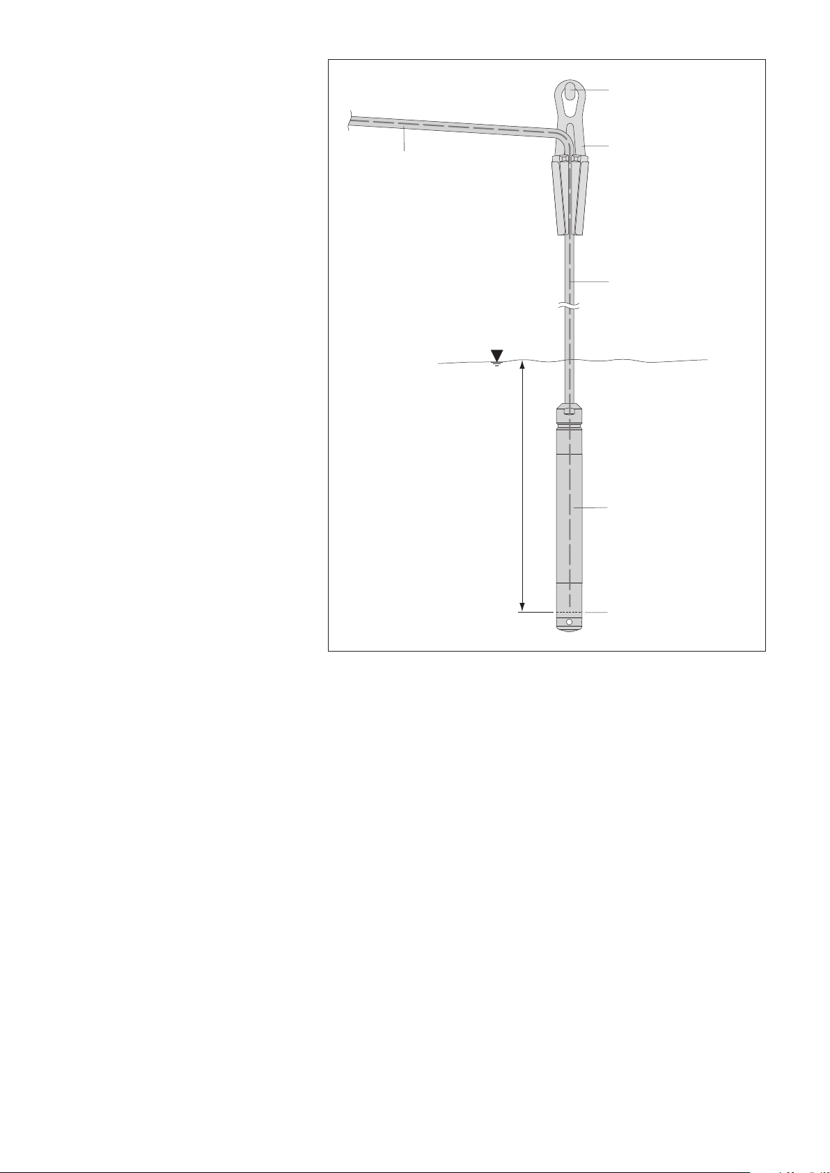
Fig. 1: Main layout of a water level station
Pressure probe OTT PLS
Pressure-sensitive membrane
of the relative pressure
measuring cell
Cable suspension
(accessory)
Pressure probe cable
(e. g. to datalogger)
Pressure compensation
capillary
Attachment hooks
Water level
with the OTT PLS pressure probe.
7
Page 8

5 Installing the pressure probe
The OTT PLS pressure probe can be used in a variety of ways, for example in
observation wells and boreholes from 1" diameter, in shafts, open waterways, and
in waterways that do not always hold water.
Caution
We do not recommend installing the pressure probe in the vicinity of port facilities,
industrial waste water discharges or areas with heavy chemical contamination.
The pressure probe is constructed from high-quality stainless steel and plastic.
However, depending on the mounting location, damaging corrosion can arise. For
more information on the materials used, see Chapter 11 "Technical data".
The pressure probe can be installed in two ways:
䊳
fixed in an individual protective device, built on location, or
䊳
hung on the pressure probe cable.
Caution
No moisture should be allowed to enter the pressure compensation capillary of the
pressure probe cable during installation! Very high air humidity can also lead to
the formation of water droplets in the pressure compensation capillary due to
temperature changes. These inevitably lead to unusable measurement results! As a
result, ensure the transport protection is left on the cable end during the whole
time it is being laid!
5.1 Installation type A: fixing the pressure probe into a protective
device
In flowing waters or waterways with a swell, the pressure probe must be fixed.
With strong currents (> 0.5 … 1 m/s) the hydrodynamic influences of the station
have to be considered in the installation. Depending on the version and mounting
of the individual components, overpressure or negative pressure can arise that can
affect the measurement result.
䡵
Determine the minimum and maximum water level at your station (e.g. staff
gauge, contact gauge). Use both values to specify the probe position. The
following conditions must be fulfilled:
– position the probe below the minimum water level if possible;
– difference between max. water level and position of the probe < measuring
range of the probe.
䡵 Fix the pressure probe according to your individual requirements in a protective
device, as shown in Figure 2, for example.
Note
The fine setting of the probe position is carried out, for example, by entering a
reference or offset value (with SDI-12/RS-485 interface) or using a scaling function of the datalogger connected.
8
Page 9
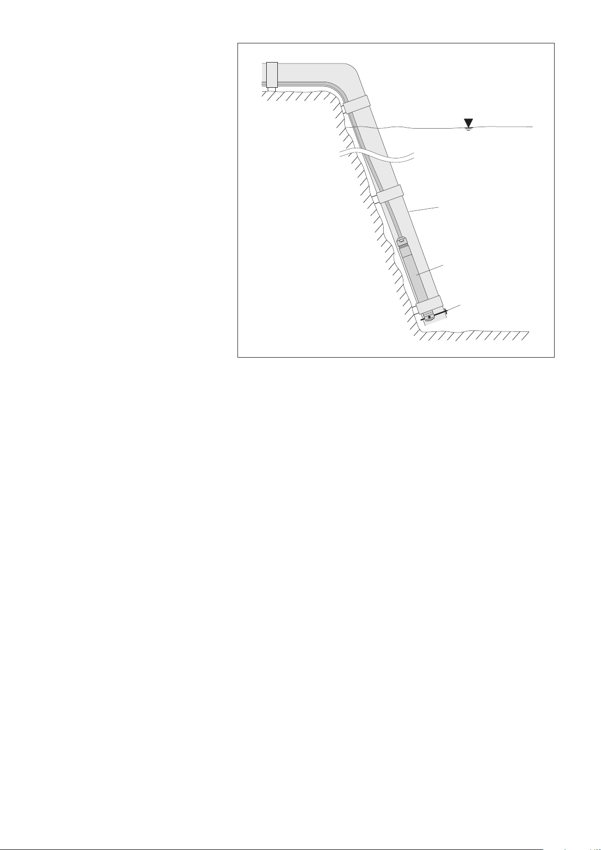
Plastic protective tube
Fixing pin
OTT PLS
Fig. 2: Installation example of the OTT PLS
pressure probe in open waterways.
With waterways with currents or swell, a
fixing pin is used to securely fasten the
probe. Push the fixing pin through the
holes in the black protective cap.
5.2 Installation type B: hanging pressure probe
See also Figure 1.
䡵
Determine the minimum and maximum water level at your station (e.g. staff
gauge, contact gauge). Use both values to specify the probe position. The following conditions must be fulfilled:
– position the probe below the minimum water level if possible;
– difference between max. water level and position of the probe < measuring
range of the probe.
䡵 Fix the cable attachment (accessory) at a suitably sized attachment point.
䡵 Carefully lower the pressure probe on the pressure probe cable to the specified
depth. There are markings on the cable every 0.25 m to assist orientation.
䡵 Lay the pressure probe cable in the opened clamping jaws of the cable attach-
ment as shown in Figure 1 and secure the pressure probe cable by pushing the
clamping jaws together. The mechanical longitudinal stability required is provided by Kevlar fibers inside the pressure probe cable. Caution: maximum
hanging depth: 50 m. (greater depths on request).
Notes
䊳
The fine setting of the probe position is carried out, for example, by entering a
reference or offset value (with SDI-12/RS-485 interface) or using a scaling
function of the datalogger connected. It is thus sufficient in many applications
to position the probe approximately.
䊳
If the pressure probe cable ends in the immediate vicinity of the cable attach-
ment: fix the Kevlar fibers at a suitable point in addition!
9
Page 10
5.3 Connecting humidity absorbing system
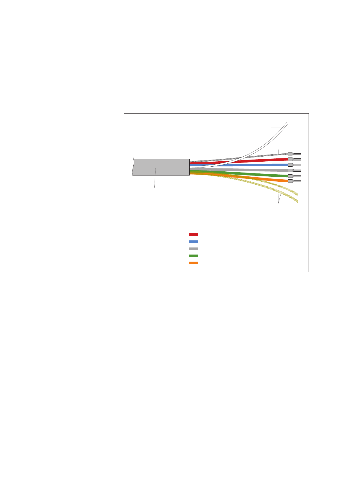
Pressure compensation capillary
Cable shielding
Kevlar fibers
Pressure probe cable
Color Assignment
red +9,6 … 28 V DC
blue GND
gray SDI-12 Data
green RS-485 A
orange RS-485 B
A humidity absorbing system must be installed for drying the surrounding air
that enters the pressure compensation capillary of the pressure probe cable!
See Appendix C and D.
Caution
Humidity entering the pressure compensation capillary leads to unusable
measurement results!
5.4 Wire assignment of the pressure probe cable
Fig. 3: Wire assignment of the
OTT PLS pressure probe cable.
10
Caution
The factory assembled pressure probe cable should only be shortened with a suitable wire stripping tool! Danger of damaging the cable!
Recommendation: Store excess cable in loops if necessary!
If necessary, the pressure probe cable can be lengthened. For this purpose, use
a suitable junction box (e.g. OTT FAD 5). This should also be large enough to hold
the humidity absorbing system. The maximum cable length for the RS-485 interface and the 4 … 20 mA interface is 1,000 m. Recommended cable type for the
RS-485 interface: shielded, twisted-pair cable. The wires intended for the power
supply can be twisted pair, but do not have to be. Recommended cable type for
the 4 … 20 mA interface: unshielded, low-voltage cable. If the additional RS-485
interface (configuring the 4 … 20 mA interface) is also to be fed to the datalogger, a twisted pair cable is also necessary in this case.
Suitable wire sizes
䊳
Up to 500 m cable length: 2 x 2 x 0.5 mm2(41 Ohm/1,000 m)
䊳
500 to 1,000 m cable length: 2 x 2 x 0.75 mm2 (27 Ohm/1,000 m)
Page 11
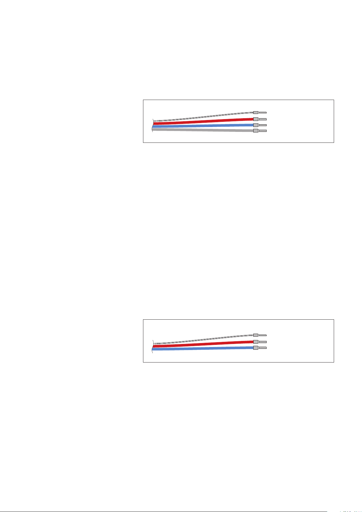
5.5 Connecting the OTT PLS to any datalogger using an SDI-12
Cable shielding
+9,6 … 28 V DC (red)
GND (blue)
Cable shielding
+9,6 … 28 V DC (red)
GND (blue)
SDI-12 Data (gray)
interface
䡵 Connect the OTT PLS to an SDI-12 input of the datalogger. Follow the datalogger
handbook when doing this. Refer to Figure 4 for the wire assignments of the
TT PLS. Wires used: red, blue, and gray. The maximum length of the cable is
O
100 m.
䡵 To achieve better protection against overloads, you can optionally connect the
cable shielding to a grounding point/equipotential busbar.
Fig. 4: Wires used with an SDI-12 interface.
Note
The standard supply voltage (12 Volt line) in an SDI-12 bus is 12 Volts and the
maximum is 16 Volts. Take this into account if other sensors are available in the
SDI-12 bus in addition to the OTT PLS sensor.
The SDI-12 commands and responses used with the OTT PLS can be found in
Chapter 6, SDI-12-Commands and Responses.
5.6 Connecting the OTT PLS to any datalogger using a 4 … 20 mA
interface
䡵 Connect the OTT PLS to a 4 … 20 mA input of the datalogger. Follow the dat-
alogger handbook when doing this. Refer to Figure 5 for the connection
assignments of the OTT PLS. Wires used: red and blue.
Maximum cable length: dependent on the level of the supply voltage and size
of the burden (load resistor). Ensure that the ohmic resistance of the pressure
probe cable together with any burden present does not exceed the maximum
permitted load resistance (see Chapter 5.7). The upper limit for the cable length
is 1,000 m in all cases.
䡵 To achieve better protection against overloads, you can optionally connect the
cable shielding to a grounding point/equipotential busbar.
Fig. 5: Wires used with a
4 … 20 mA interface.
If the OTT PLS is to be configured via
the RS-485 interface, the green and
orange wires are required in addition.
5.7 Determining the maximum load resistance at the 4 … 20 mA
interface
The load resistance (burden + ohmic resistance of the connection cable) connected
to the OTT PLS must not exceed a specific maximum value. This value depends on
the level of the supply voltage of the OTT PLS. If the load resistance is greater, the
loop current* can no longer be evaluated. Smaller load resistances are allowed.
* Due to the imposed (controlled) current by the OTT PLS of the 4 … 20 mA interface (=^measured value)
11
Page 12
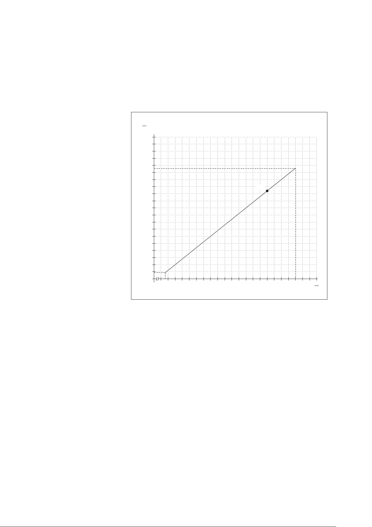
䡵 See the following diagram for the maximum load resistance applicable to your
10
15
20
25
30
U
V
100
0
200
300
400
500
600
700
800
R
Ω
900
1000
Example
power supply. Alternatively, the maximum load resistance can be calculated
according to the formula:
R
load (max)
= (U
– 8.5 V)/0.025 A
supply
Example: Power supply 24 Volt ➝ max. load resistance 620 Ohm.
The OTT PLS delivers a loop current corresponding to the measured value for a
oad resistance of up to 620 Ohm.
l
䡵 Dimension the connected electrical circuit accordingly. Check the input resis-
tance of the connected peripheral device for this purpose.
Fig. 6: Diagram to determine the
maximum load resistance as a
function of the power supply.
Minimum power supply: 9.6 V
Maximum power supply: 28 V
Burden tolerance: 0.1 %/15 ppm.
(Burden = load resistor).
12
5.8 Note on using the 4 … 20 mA interface
䊳
Behavior when switching on the 4 … 20 mA interface
After providing the supply voltage, it takes approx. 7 seconds for the loop current
to take on the value proportional to the water level. (In the first 7 seconds, the
loop current is between 3 and 4 mA.) Afterwards, the pressure probe updates
the loop current every 2 seconds.
䊳
Loop current when configuring the 4 … 20 mA interface
If there is a communication via the RS-485 interface, the loop current is higher
than the appropriate level for the measured value by several mA. After the end
of the communication, it takes approx. 250 ms until the loop current takes on
the appropriate value again.
5.9 Note on using the RS-485 interface
The RS-485 interface is designed and tested for use with OTT dataloggers.
In this case, the transmission protocol via the physical RS-485 interface is the
SDI-12 protocol
. Connecting OTT PLS via the RS-485 interface to the OTT netDL/
OTT DuoSens ➝ see Appendix A, Method B.
OTT provides no guarantee of functionality if you connect the OTT PLS to the
data logger of a third-party manufacturer via the RS-485 interface!
Page 13

6 SDI-12 Commands and Responses
6.1 Standard commands
All SDI-12 standard commands are implemented in the OTT PLS. The following SDI-12 standard commands are relevant for
the operation of the OTT PLS:
Command Response Description
!
a
I!
a
<CR><LF>
a
l3ccccccccmmmmmm …
a
vvvxxxx<CR><LF>
…
aAb! b<CR><LF>
?! a<CR><LF>
aM!
atttn<CR><LF>
and after 1 … 60 second(s)
a<CR><LF>
aD0!
a<value1><value2>…
<value3><value4><CR><LF>
…
Confirmation active
a – sensor address; factory setting = 0
Send identification
a – Sensor address
l3 – SDI-12 protocol version
cccccccc – manufacturer identification (company name)
mmmmmm – Sensor identification
vvv – Sensor version (firmware)
xxxxxx – Serial number
Answer OTT PLS = 013OTTHACH PLS000100123456
Change sensor address
a – old sensor address
b – new sensor address
Query sensor address
a – sensor address
Starting the measurement
1
)
a – Sensor address
ttt – Time in seconds until the sensor has
determined the measurement result
Answer OTT PLS = 001 … 060
1)
n – Number of measured values
2)
Answer OTT PLS = 2
or 4
a<CR><LF> – Service request
Send data
a – sensor address
<value1> –
average2)level/pressure value
measured value formats:
m ➝ pbbbb.eee
cm ➝ pbbbbbbbb
ft ➝ pbbbbb.ee
mbar ➝ pbbbbb.ee
psi ➝ pbbbb.eee
<value2> – temperature value
measured value formats:
°C and °F ➝ pbbb.e
<value3>2) – minimum level/pressure value within
the actual measuring interval
measured value formats: see above
<value4>
2)
– maximum level/pressure value within
the actual measuring interval
measured value formats: see above
p – sign (+,–)
b – numbers (before the decimal point)
Output is without leading zeroes!
e – digits after the decimal point
aMC! atttn<CR><LF>
and after 2 seconds
a<CR><LF>
1)
depending to the setting of measuring time (aOXM)
2)
if measuring time (aOXM) is ≥ 3 seconds
Start the measurement and request CRC (Cyclic Redundancy
Check). For details see command aM! .
The answer to the following a D 0! command is extended
by a CRC value:
a< valu e 1><v a lue2 ><C R C ><CR > <LF>
13
Page 14

Command Response Description
aC! atttnn<CR><LF>
aCC! atttnn<CR><LF>
aM1! atttn<CR><LF>
and immediately afterwards
a<CR><LF>
aD0! a<value><CR><LF>
Start concurrent measurement (simultaneous measurement
with multiple sensors on one bus feed). For more details, see
command aM!. The number of measured values in the
answer to this command is two-digit: nn = 02.
Start concurrent measurement (simultaneous measurement
with multiple sensors on one bus feed) and request CRC
(Cyclic Redundancy Check). For more details, see command
M!. The number of measured values in the answer to this
a
ommand is two-digit: nn = 02.
c
he answer to the following aD0! command is extended by
T
a CRC value: a<value1><value2><CRC><CR><LF>
Query status of the last measurement
a – Sensor address
ttt – Time in seconds until the sensor has made
the result of the system test available
Answer OTT PLS = 000
n – Number of measured values
Answer OTT PLS = 1
a<CR><LF> – Service request
Send data (after aM1!, aMC1!, aC1!, aCC1!)
a – Sensor address
<value> – Status of the last measurement
+0 = no hardware defect found
+128 = flash memory defective
+256 = Watchdog error
+512 = memory defective
+1024 = pressure cell defective
+2048 = D/A converter defective
aMC1! atttn<CR><LF>
and immediately afterwards
a<CR><LF>
aC1! atttnn<CR><LF>
aCC1! atttnn<CR><LF>
aV! atttn<CR><LF>
and immediately afterwards
a<CR><LF>
Query the status of the last measurement and request CRC
(Cyclic Redundancy Check). For details see command aM1!.
The answer to the following aD0! command is extended by
a CRC value: a<value><CRC><CR><LF>
Query the status of the last measurement in concurrent mode
(simultaneous measurement with multiple sensors on one bus
feed). For more details, see command aM! The number of
measured values in the answer to this command is two-digit:
nn = 02.
Query the status of the last measurement in concurrent mode
(simultaneous measurement with multiple sensors on one bus
feed) and request CRC (Cyclic Redundancy Check). For more
details, see command aM! The number of measured values in
the answer to this command is two-digit: nn = 02.
The answer to the following aD0! command is extended by
a CRC value: a<value><CRC><CR><LF>
Carrying out a system test
a – Sensor address
ttt – Time in seconds until the sensor has made
the result of the system test available
Answer OTT PLS = 000
n – Number of measured values
Answer OTT PLS = 1
a<CR><LF> – Service request
14
Page 15

Command Response Description
aD0! a<value><CR><LF>
Send data (after aV!)
a – Sensor address
<value> – Result of the system test
+0 = no hardware defect found
+128 = flash memory defective
+256 = Watchdog error
+512 = memory defective
+1024 = pressure cell defective
+2048 = D/A converter defective
More information on the SDI-12 standard commands can be found in the document "SDI-12; A Serial-Digital Interface Standard for Microprocessor-Based Sensors, Version 1.3" (see Internet page "www.sdi-12.org").
6.2 Advanced SDI-12 commands
All advanced SDI-12 commands begin with an "
O" for OTT. With these commands, it is possible to configure the OTT PLS
using the transparent mode of a datalogger.
Command Response Description
䊳
Setting/reading the level/pressure measurement values
aOSU<value>!
aOSU!
a<value><CR><LF>
a<value><CR><LF>
Set unit
Read out unit
a – Sensor address
<value> – Units for level
+0 = m; factory setting
+1 = cm
+2 = ft
The level measurement is carried out with compensation for water density, water temperature
and local gravitational acceleration.
Units for pressure measurement
+3 = mbar
+4 = psi
Pressure measurement is carried out without
compensation!
Caution
If settings for the parameters "Offset", "Reference value",
"Upper limit" or "Lower limit" have been made before
changing the unit, they must be reset! There is no automatic
conversion of the parameters set!
䊳
Setting/reading the temperature value units
aOST<value>!
aOST!
a<value><CR><LF>
a<value><CR><LF>
Set unit
Read out unit
a – Sensor address
<value> – +0 = °C; factory setting
+1 = °F
15
Page 16

Command Response Description
䊳 Set/read local gravitational acceleration
aOXG<value>!
aOXG!
䊳 Set/read average water density
a<value><CR><LF>
a<value><CR><LF>
Set local gravitational acceleration
Read out local gravitational acceleration
a – Sensor address
<value> – b.eeeee
b – numbers before the decimal point
c – numbers after the decimal point
Value range: 9.78036 … 9.83208 m/s
Factory setting = 9.80665 m/s
2
2
The gravitational acceleration at the earth's surface fluctuates
2
between 9.78036 m/s
the poles. Also, it decreases by 0.003086 m/s
at the equator and 9.83208 m/s2at
2
for each
kilometer of elevation above sea level.
Formula for the local gravitational acceleration "g" in m/s
2
g = 9.780356 (1 + 0.0052885 sin
α – 0.0000059 sin22α)
2
– 0.003086h
α latitude; h = height above sea level in km
(Source: Jursa, A.S., Ed., Handbook of Geophysics and the
Space Environment, 4th ed., Air Force Geophysics Laboratory, 1985, pp. 14-17).
Example
Local gravitational acceleration in Kempten: At a height
above sea level of 669 m and a latitude of 47.71°, a local
2
gravitational acceleration of 9.80659 m/s
results.
Note
The OTT PLS is preset to an average value for Germany
(Kassel). The measurement deviation caused by gravitational
acceleration is ±3 mm in Germany (Flensburg – Oberstdorf).
This measurement error is compensated by inputting the
local gravitational acceleration.
:
aOXR<value>!
aOXR!
䊳 Set/read depth measurement measuring mode
aOAA<value>!
aOAA!
a<value><CR><LF>
a<value><CR><LF>
a<value><CR><LF>
a<value><CR><LF>
Set medium water density
Read out medium water density
a – Sensor address
<value> – b.eeeee
b – numbers before the decimal point
a – numbers after the decimal point
Value range: 0.50000 … 2.00000 kg/dm
3
Factory setting = 0.99997 kg/dm3 (at 3.98 °C)
With this command you can set the actual density of the
water at your station for level/depth measurement. For
example, this is worthwhile at stations with brackish water.
Set measuring mode depth measurement
Read out measuring mode
a – Sensor address
<value> – +0 = depth measurement measuring mode
deactivated
+1 = depth measurement measuring mode
activated
Caution
If settings for the parameters "Offset", "Reference value",
"Upper limit" or "Lower limit" have been made before
changing the measuring mode, they must be reset! There is
no automatic conversion of the parameters set!
16
Page 17

Command Response Description
䊳 SDI-12-/RS-485 interface – setting/reading offset for level/depth measurement
aOAB<value>!
aOAB!
a0022<CR><LF>
and after 2 seconds
a<CR><LF>
a<value><CR><LF
Setting the offset value
Reading out the offset value
a – Sensor address
<value> – pbbbb.eee
p – sign (+,–)
b – numbers (before the decimal point)
e – numbers after the decimal point
a<CR><LF> – Service request
Input/output is without leading zeroes.
Value range: –9999.999 … +9999.999
Factory setting = +0.000
With this command you can add a linear offset
(positive/negative) to a level/depth measurement value.
After setting the offset value, the OTT PLS automatically starts
a measurement. After receiving the service request, check the
measured value with command aD0!. After an unsuccessful
entry, the pressure probe replies with a new service request.
Caution
This command overwrites any set reference value!
Example
Measured value = +10.040 m
Offset = –0.200 m
Output = +9.840 m
Note
If the unit is changed afterwards (aOSU<value>!), rounding errors of ±0.001 are possible.
䊳 SDI-12-/RS-485 interface – setting/reading reference value for level/depth measurement
aOAC<value>!
a0022<CR><LF>
Setting the reference value
and after 2 seconds
a<CR><LF>
aOAC!
a<value><CR><LF>
Reading out the reference value
a – Sensor address
<value> – pbbbb.eee
p – sign (+,–)
b – numbers (before the decimal point)
e – numbers after the decimal point
a<CR><LF> – Service request
Input/output is without leading zeroes.
Value range: –9999.999 … +9999.999
Factory setting = +0.000
With this command you can establish a reference to a level
zero, for example, by entering a reference value for
level/depth measurement. After setting the reference value,
the OTT PLS automatically starts a measurement. After
receiving the service request, check the measured value with
command aD0!. After an unsuccessful entry, the pressure
probe replies with a new service request.
17
Page 18

Command Response Description
Caution
This command overwrites any set offset value.
Example
Measured value = +2.100 m
reference value = +1.500 m
output = +1.500 m
(offset calculated by the OTT PLS and applied to all other
measured values = +0.600 m)
Note
If the unit is changed afterwards (aOSU<value>!), rounding errors of ±0.001 are possible.
䊳
Setting/reading the measuring time
et measuring time
aOXM<value>!
aOXM!
a<value><CR><LF>
a<value><CR><LF>
S
Read out measuring time
a – Sensor address
<value> – bb
b – numbers
Input/output is without leading zeroes!
Value range: 1 … 60 [s]
Factory setting = 2 [s]
Note
If measuring time is ≥ 3 seconds, <value3> and
<value4> appear aditionally in the response to an aD0!
command. With 1 second measuring time, the response is
identical to 2 seconds measuring time.
䊳 4 … 20 mA interface – setting/reading the lower limit
aOPA<value>!
aOPA!
䊳 4 … 20 mA interface – setting/reading the upper limit
aOPB<value>!
aOPB!
a<value><CR><LF>
a<value><CR><LF>
a<value><CR><LF>
a<value><CR><LF>
Setting the lower limit
Reading out the lower limit
a – Sensor address
<value> – pbbbb.eee
p – sign (+,–)
b – numbers (before the decimal point)
e – numbers after the decimal point
Input/output is without leading zeroes!
Value range: –9999.999 … +9999.999
Factory setting = +0.000
Note
If the unit is changed afterwards (aOSU<value>!), rounding errors of ±0.001 are possible.
Setting the upper limit
Reading out the upper limit
a – Sensor address
<value> – pbbbb.eee
p – Sign (+,–)
b – Numbers (before the decimal point)
e – Numbers after the decimal point
Input/output is without leading zeroes.
Value range: –9999.999 … +9999.999
Factory setting = +0.000
18
Note
If the unit is changed afterwards (aOSU<value>!), rounding errors of ±0.001 are possible.
Page 19
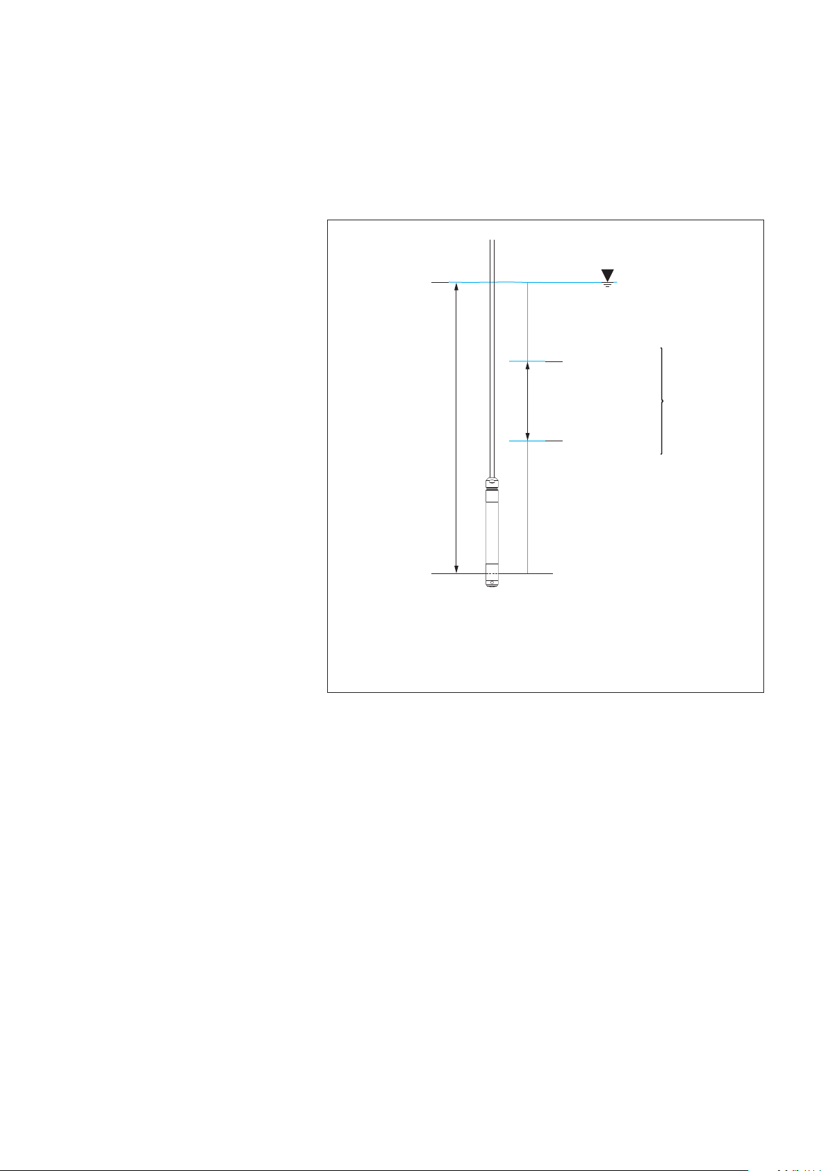
Using the commands "setting/reading the upper/lower limit" you can scale the
15 m =^ 20 mA
(upper limit)
10 m =
^
4 mA
(lower limit)
Measurement
output
scaled to
5 meter
water level
change
Figure not to scale!
20 m =
^
20 mA
0 m =
^
4 mA
with scaling
Measurement output
without scaling
measurement output of an OTT PLS to a smaller measuring range. Where you do
ot require the whole measuring range, this has the advantage that a higher
n
resolution for the 4 … 20 mA interface can be achieved. Example: A measuring
range of 16 mA is available for 5 m water level change (e.g. lower limit =
+10,000 m; upper limit = +15,000 m. See Figure 7). At the same time, you can
use these commands to apply a linear offset (positive/negative) to the measured
alues of the 4 … 20 mA interface.
v
Fig. 7: Scaling measurement output
of the 4 … 20 mA interface to a
smaller measuring range.
Example: OTT PLS with
measuring range 0 … 20 m.
19
Page 20
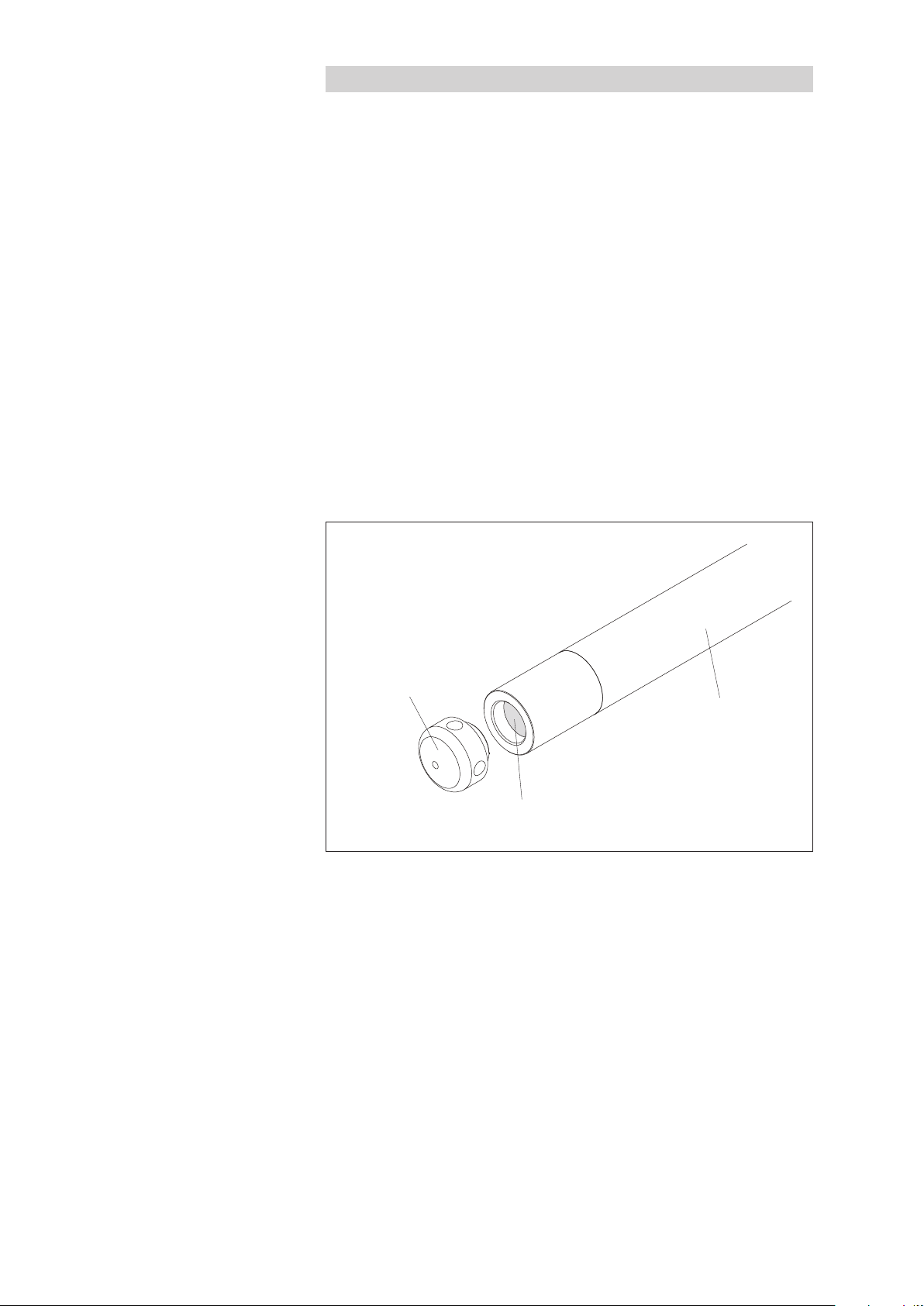
7 Carrying out maintenance work
Black
protective cap
Pressure sensitive
measuring cell membrane
Pressure probe
OTT PLS
The high-quality design of the OTT PLS makes regular cleaning work unnecessary.
Even a thin build-up of deposits on the measuring cell will not appreciably affect
the measurement results.
If very heavy contamination occurs at the station due to algae, mud, vegetation or
sediment, the pressure probe should be checked from time to time. For example,
imprecise or implausible measured values may indicate a "blocked" measuring
cell. If necessary, the pressure probe can be cleaned easily.
How to clean the pressure probe
䡵 Uninstall OTT PLS (see Chapter 5).
䡵 Remove the black protective cap.
䡵 Clean the measuring cell carefully using a brush (hard bristles). Lime scale
deposits can be removed using a common household scale remover. Make sure
to follow the use and safety instructions of the scale remover!
䡵 Rinse the pressure probe thoroughly with clear water!
䡵 Reattach the black protective cap.
䡵 Reinstall OTT PLS (see Chapter 5).
䡵 Specifying measured values, comparing with a reference value (staff gauge,
contact gauge) and correcting as necessary (enter reference or offset value or
via scaling function of the datalogger attached).
Fig. 8: Cleaning the pressure probe.
20
Page 21

8 Searching for disruptions/troubleshooting
Sensor does not respond to the SDI-12 interface
䊳
Sensor correctly connected to a datalogger with SDI-12 input (master)?
➝ Correct connection assignment.
䊳
Polarity of the supply voltage reversed?
➝ Correct connection assignment.
䊳
Supply voltage < 9.6 V or > 28 V?
➝ Adjust level of voltage supplied (check the length and cross-section of the
connection cable).
䊳
Is the supply voltage not direct current?
➝ Only operate sensor with direct current.
䊳
Does the sensor address of the OTT PLS correspond with the sensor address
that the datalogger uses?
➝ Correct sensor address.
4 … 20 mA loop current is missing
䊳
Is the sensor correctly connected to a datalogger or peripheral device with
4 ... 20 mA input (check polarity)?
➝ Correct connection assignment.
䊳
Is the 4 .. 20 mA loop current correctly supplied through datalogger or OTT
PLS (internal/external supply)?
➝ Correct connection assignment.
Measured value varies or is not present
䊳
Sensor dirty?
➝ Clean sensor carefully. See Chapter 7, "Carrying out maintenance work".
䊳
Installation of the sensor steady (e.g. movement from swell)?
➝ Optimize installation.
䊳
Drops of water in the pressure compensation capillary?
➝ Replace pressure probe.
Status output at the 4 … 20 mA interface
The OTT PLS with 4 … 20 mA interface indicates the operational state or any
faults that might occur via the loop current:
Loop current Status
4 … 20 mA correct
3.4 mA FLASH memory defective
3.3 mA Watchdog error
3.2 mA Failed memory
3.1 mA Pressure cell defective
3.0 mA Analog converter defective
<3.0 mA Loop current error: broken line, loop supply missing
3.6 mA Measurement range not reached (underflow)
or global error
3.8 … <4.0 mA Marginally below measurement range: The pressure
probe delivers an output signal proportional to the
water level, but is outside the specification (under range)
>20.0 … 20.5 mA Marginally above measurement range: The pressure
probe delivers an output signal proportional to the
water level, but is outside the specification (over range)
21.0 mA Measuring range exceeded (overflow)
Status output at the SDI-12 interface
see SDI-12 command aM1!
21
Page 22
9 Repair
䡵 With a problem with the device, use Chapter 8, "Error messages/error correc-
tion" to see if you can resolve the problem yourself.
䡵 In the case of device defects, please contact the repair center of OTT:
OTT Hydromet GmbH
Repaircenter
Ludwigstrasse 16
87437 Kempten · Germany
Telephone +49 831 5617-433
Fax +49 831 5617-439
[email protected]
Caution: Only have a defective OTT PLS checked and repaired by the OTT
repair center. Under no circumstances carry out any repairs yourself.
Any repairs or attempted repairs carried out by the customer will result
in the loss of any guarantee rights.
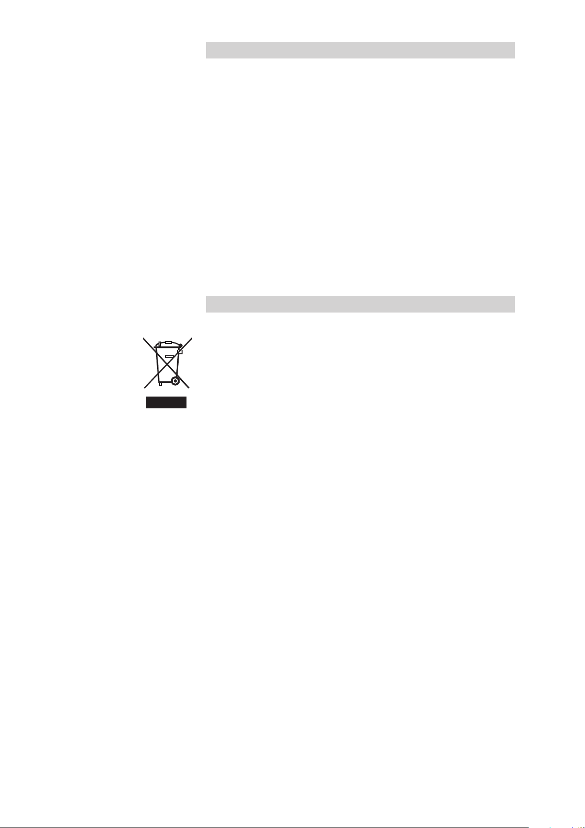
10 Note about the disposal of old units
Within the member countries of the European Union
In accordance with the European Union guideline 2002/96/EC, OTT takes back
old devices within the member countries of the European Union and disposes of
them in an appropriate way. The devices concerned by this are marked with the
symbol shown here.
䡵 For further information on the return procedure, please contact your local sales
contact. You will find the addresses of all sales partners in the internet on
"www.ott.com". Please take into consideration also the national implementation
of the EU guideline 2002/96/EC of your country.
For all other countries
䡵 Dispose of the OTT PLS properly after taking out of service.
䡵 Observe the regulations valid in your country for the disposal of electronic
devices.
䡵 Never put the OTT PLS into the normal household waste.
Materials used
See Chapter 11 "Technical data"
22
Page 23

11 Technical Data
Water level
Measuring range 0 … 4 m water column (0 ... 0.4 bar)
0 … 10 m water column (0 ... 1 bar)
0 … 20 m water column (0 ... 2 bar)
0 … 40 m water column (0 ... 4 bar)
0 … 100 m water column (0 ... 10 bar)
Resolution (SDI-12 interface) 0.001 m; 0.1 cm; 0.01 ft;
0.1 mbar; 0.001 psi
Accuracy (linearity + hysteresis)
SDI-12 interface ≤ ± 0.05 % of full scale
4 … 20 mA interface ≤ ±0.1% of full scale;
10 ppm/°C at 20 °C
Long-term stability (linearity + hysteresis) ≤ ± 0.1 %/a of full scale
Zero point drift ≤ ± 0.1 % of full scale
Units m, cm, ft, mbar, psi
Overload protection for the measuring cell
(without permanent mechanical damage)
0 ... 0.4 bar 4 bar
0 ... 1 bar 10 bar
0 ... 2 bar 15 bar
0 ... 4 bar 25 bar
0 ... 10 bar 40 bar
Pressure sensor ceramic, capacitive; temperature-
compensated
Temperature-compensated operating range –5 °C … +45 °C
Temperature
Measuring range –25 °C … +70 °C
Resolution 0.1 °C
Accuracy ± 0.5 °C
Units °C, °F
Temperature sensor NTC
Supply voltage +9,6 … +28 V DC, typically 12/24 V DC
Current consumption
SDI-12 sleep mode < 600 µA
SDI-12 active mode < 3.6 mA
Interfaces SDI-12 version 1.3
RS-485 (SDI-12 protocol)
4 … 20 mA; 2-wire (scaleable)
Reaction times
Boot time 5,000 ms
Measuring time <2,000 ms
Storage temperature –40 °C … +85 °C
23
Page 24

Mechanical Data
Dimensions
Pressure probe L x Ø 195 mm x 22 mm
Cable length 1 … 200 m (with SDI-12 interface:
1 … 100 m)
Weight
pressure probe approx. 0.3 kg
Material
Pressure probe housing POM, stainless steel 1.4539 (904 L),
resistant to sea water
Cable jacket PUR
Seals Viton
Separating membrane ceramic Al
2O3
; 96 %
Type of protection IP 68
Performance classification in
accordance with DIN EN ISO 4373
Measurement reliability Performance class 1
Temperature range Temperature class 2
Relative humidity Class 1
EMC limits complies with EN 61326-1:2013
24
Page 25
Appendix A – Connecting the OTT PLS via SDI-12 or RS-485 interface to an
SDI-12
Input
Pressure probe cable
A
4
31 2
OTT DuoSens
+9.6 … 28 V
GND
SDI-12 Data
SDI-12
Input
C
4
31 2
OTT netDL
+9.6 … 28 V
GND
SDI-12 Data
RS-485
Input
A
431 2
OTT DuoSens
Pressure probe cable
+9.6 … 28 V
GND
RS-485
Input
C
431 2
OTT netDL
+9.6 … 28 V
GND
RS-485-B
RS-485-A
RS-485-B
RS-485-A
OTT netDL or OTT DuoSens datalogger
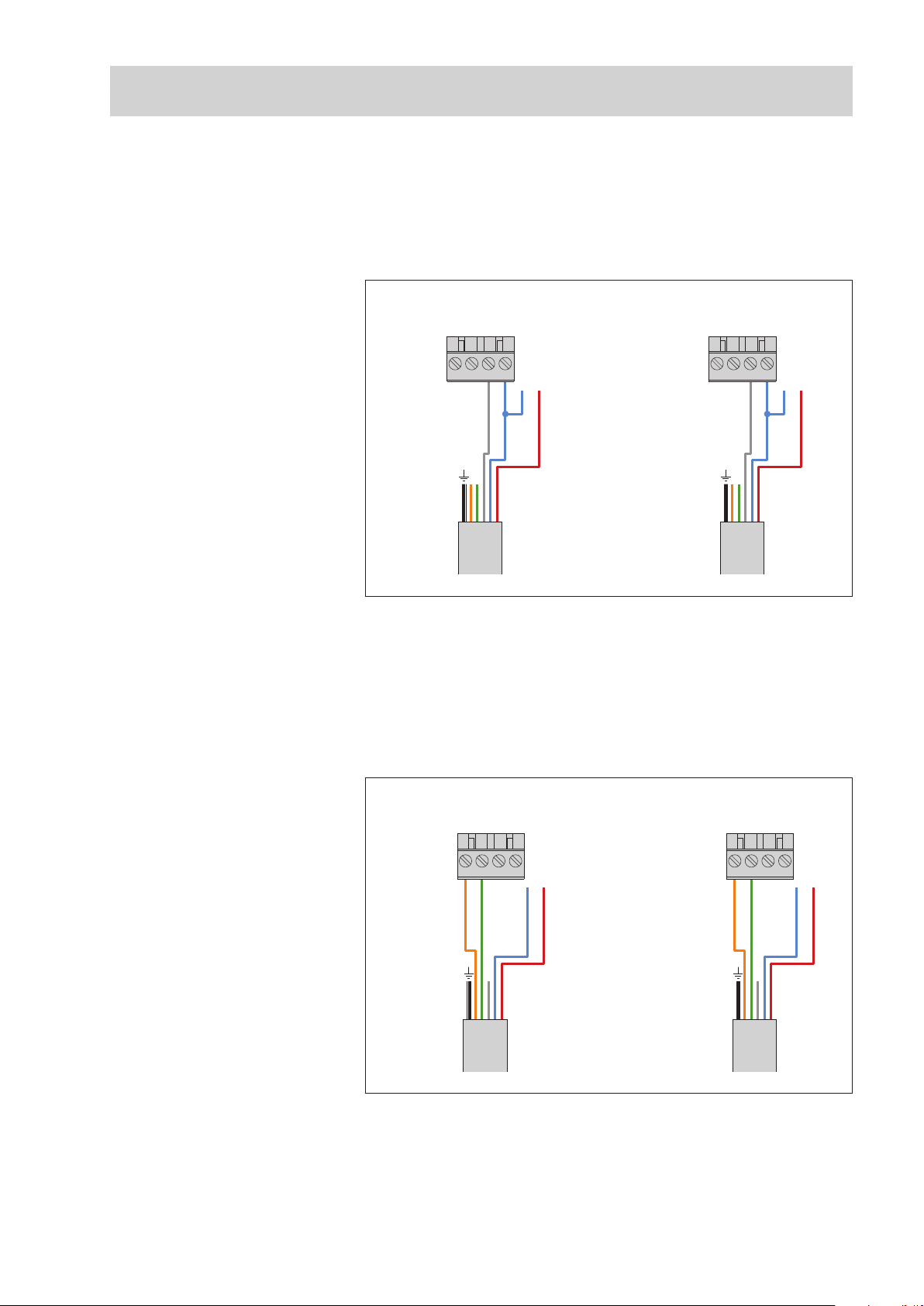
Method A: Connecting the OTT PLS via the SDI-12 interface (protocol and
physical interface: SDI-12). The maximum length of the cable is 100 m.
䡵 Connect the OTT PLS to the OTT netDL IP datalogger or to the OTT DuoSens
ompact Datalogger as shown in Figure 9. Also refer to OTT netDL or OTT
C
DuoSens Operating Instructions.
Fig. 9: Connecting the OTT PLS
to an OTT netDL or OTT DuoSens using
an SDI-12 interface.
The letters above the screw terminal
strips identify the connectivity options avail-
able on the OTT netDL/OTT DuoSens.
Method B: Connect OTT PLS using the physical RS-485 interface (SDI-12 protocol
via physical RS-485 interface). The maximum length of the cable is 1,000 m.
䡵 Connect the OTT PLS to the OTT netDL IP datalogger or to the OTT DuoSens
Compact Datalogger as shown in Figure 10. Also refer to OTT netDL or OTT
DuoSens Operating Instructions.
Fig. 10: Connecting the OTT PLS to a to an
OTT netDL or OTT DuoSens using an
RS-485 interface (SDI-12 protocol).
The letters above the screw terminal
strips identify the connectivity options avail-
able on the OTT netDL/OTT DuoSens.
䡵 To achieve better protection against overloads, you can optionally connect the
cable shielding to a grounding point/equipotential busbar.
25
Page 26

Configuring the OTT netDL/OTT DuoSens for the OTT PLS with
SDI-12 interface
Create an OTT netDL/OTT DuoSens channel with "SDI-12 Master" or "OTT SDI
䡵
RS485" function block (Serial sensors tab).
䡵 Apply the following settings:
Fig. 11: Setting the operating parameters of
the OTT netDL/OTT DuoSens "SDI-12 Mas-
ter" function block.
The function block "OTT SDI RS485"
is set in the same way.
䊳
Terminal block OTT netDL "OTT SDI RS485": C 1-2 (default)
OTT netDL "SDI-12 Master" C 3-4 (default)
OTT DuoSens "SDI-12 Master" A 3-4 (default)
OTT DuoSens "OTT SDI RS485": A 1-2 (default)
Terminal block (screw terminal strip) of the OTT netDL
OTT DuoSens to which the PLS is connected.
䊳
Slave address SDI-12 bus address. Each slave address may only be
allocated once to an SDI-12 bus feed. (Check/set: Use
the "OTT SDI-12 Interface" tool of the operating program.)
Default setting: "0" (only one OTT PLS is connected to
the terminal block with no bus operation).
䊳
Value no. Identifies which value the OTT PLS is recording on this
channel.
n "M!" Measuring Mode: Water level = 1,
– I
temperature = 2
– I
n "M1!" Measuring Mode
: Status of the last measure-
ment = 1
䊳
Measurement mode – "M!" for water level and temperature
– "M1!" for the status of the last measurement.
䊳
Concurrent Mode* ☑: Uses the Concurrent Measuring Mode (C!, C1!)
instead of the SDI-12 default Measuring Mode (M!,
M1!). This allows simultaneous measurement using multiple sensors connected to a bus line (the sensors
respond to a measurement command without service
request). The sensors must support version 1.2 or later
of the SDI-12-Standard. For further information on the
Concurrent Mode, please refer to the SDI-12-Standard
(please visit "www.sdi-12.org"). This mode is helpful
when multiple sensors are connected to one single bus
line and a longer measuring time and the same query
interval are used for the sensors.
/
26
* only in combination with an OTT netD
Page 27

䊳
I
nstantaneous value
* ☑: Upon an instantaneous value request (via LCD display
and jog shuttle), the OTT netDL sends a command to the
OTT PLS to start a measurement. Until this measurement is
complete, the LCD display uses to the last measured value
(or the instantaneous value last displayed, whichever is
most recent). On the display this is identified by an "s" to
the right of the channel number (sensor number). After
completing the measurement, the new measured value
appears without additional identification.
☐: Shows the last measured value of the sensor (measured
value of the last query interval) for an instantaneous value
request. On the display, this is identified by an "s" to the
ight of the channel number (sensor number), (also refer to
r
the OTT netDL IP Datalogger Operating Instructions, Chapter 9.1). This setting is helpful for sensors for which a
longer measuring period and shorter query interval is
sed.
u
䊳
alue no./
V
Virtual Terminal ID
䡵 In the appropriate "Channel" function blocks, set the required units and num-
ber of decimal places (m: 3; cm: 0; ft: 2; mbar: 1; psi: 3;
°C: 1; °F: 1; Status: 0).
* Only in combination with an OTT netDL
Allocation of the additional measured value of the OTT
LS which is not recorded in this channel to the virtual ter-
P
minal (only for the "M!" Measuring Mode; temperature
value).
Notes:
䊳
To record the two measured values of an OTT PLS, two channels in the
OTT netDL/OTT DuoSens are therefore required. The first channel contains the "SDI-12 Master" or "OTT SDI RS485" as an input signal. The other channel
contains a "Virtual Sensor" function block (V02) as an input signal. Of course,
only one single measured value can be recorded. In this case, no entry is
required in the "Value no./Virtual terminal ID." box.
When the status of the last measurement is to be recorded as well, an additional channel including the "SDI-12 Master" or "OTT SDI RS485" function block
and the "M1!" Measuring Mode are required.
䊳
Further information on the SDI-12 commands and responses used can be found
in Chapter 6, "SDI-12-commands and responses".
䊳
The OTT PLS provides the measurement results for retrieval 2 seconds after the
SDI-12 commando aM!.
27
Page 28
Appendix B – Connecting the OTT PLS to an OTT netDL or OTT DuoSens datalogger
4 … 20 mA
Input
G … K1) / G … M
2)
431 2
OTT netDL
4 … 20 mA
Input
G … K1) / G … M
2)
431 2
OTT netDL
Pressure probe cable
+9.6 … 28 V
I in –
I in +
I in +
I in –
1
)
OTT netDL 500
2
)
OTT netDL 1000
4 … 20 mA
Input
C … F*
431 2
OTT DuoSens
* only with a OTT DuoSens
with analog extension
4 … 20 mA
Input
C … F*
431 2
OTT DuoSens
Pressure probe cable
+9.6 … 28 V
I in –
I in +
I in +
I in –
using a 4 … 20 mA interface
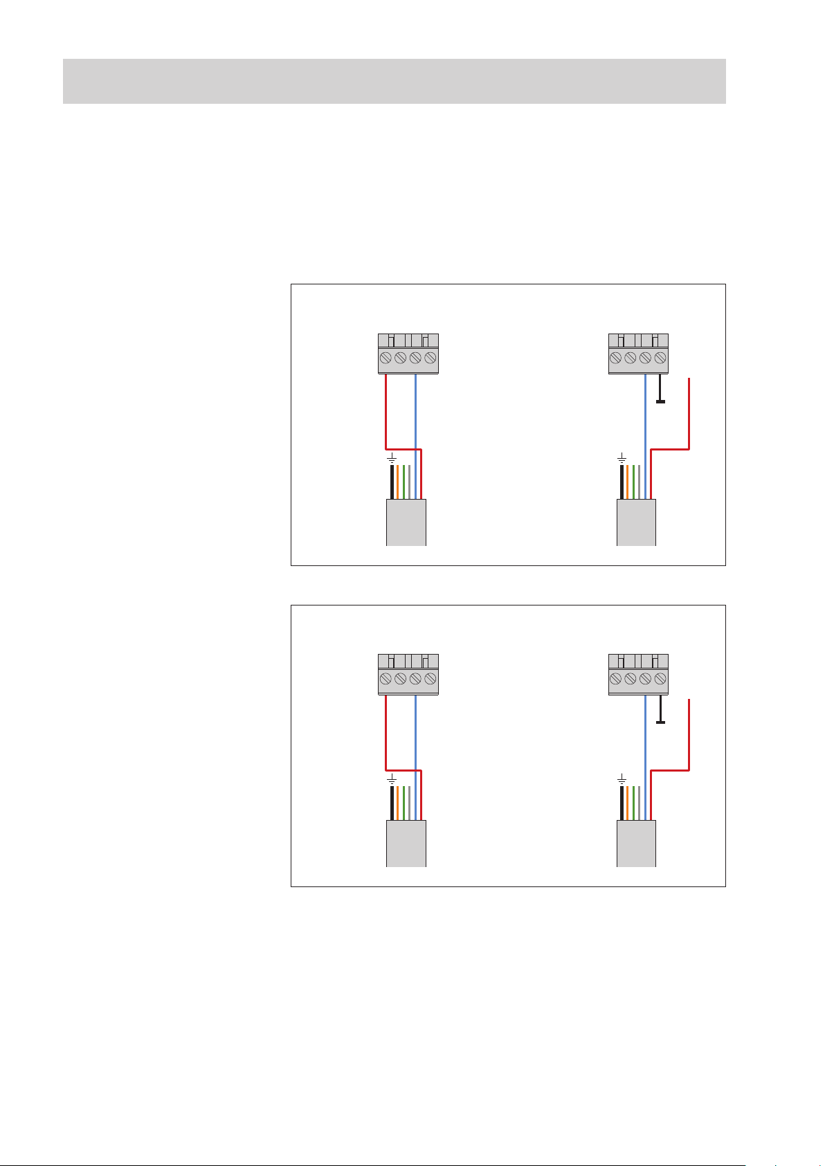
Connect the OTT PLS to the OTT netDL IP datalogger or to the OTT DuoSens
䡵
ompact Datalogger as shown in Figures 12 and 13. Take note of the operat-
C
ng instructions for the OTT netDL/OTT DuoSens.
i
aximum cable length: dependent on the level of the supply voltage and size
M
f the burden (load resistor). Ensure that the ohmic resistance of the connection
o
able together with any burden present does not exceed the maximum permitted
c
load resistance (see Chapter 5.7). The upper limit for the cable length is 1,000 m
in all cases.
Fig. 12: Connecting the OTT PLS to the
OTT netDL using a 4 … 20 mA interface.
The letters above the screw terminal
strip identify the possible connections
on the OTT netDL..
The supply for the loop current and the
supply of the OTT PLS is made, in the
application example shown, directly from
the OTT netDL.
Fig. 13: Connecting the OTT PLS to an
OTT DuoSens using a 4 … 20 mA inter-
face.
The letters above the screw
terminal strip identify the possible
connections on the OTT DuoSens.
The supply for the current loop and the
supply of the OTT PLS is made in the
application example shown on the left
directly from the OTT DuoSens.
28
䡵 To achieve better protection against overload, you can optionally attach the
cable shielding to a ground point/potential equalization panel.
Page 29

Configuring OTT netDL/OTT DuoSens for OTT PLS with 4 … 20 mA
interface
䡵 Create an OTT netDL/OTT DuoSens channel with function block
"U/I/Pt100/"… ("Analog sensors" tab).
䡵 Apply the following settings:
Fig. 14: Setting operating parameters of
the OTT netDL/OTT DuoSens
"U/I/Pt100/…" function block.
䊳
Terminal block OTT netDL 500: G … K
TT netDL 1000: G … M
O
TT DuoSens: C … F
O
erminal block used (screw terminal strip)
T
of the OTT netDL/OTT DuoSens.
䊳
Measurement mode – with internal supply:
"I 4-20 mA int."
– with external supply:
"I 4-20 mA ext."
䊳
Sensor lag time (s) switches on the OTT netDL/OTT DuoSens
input 7 seconds before the actual measurement process
䊳
□
If required: record error codes on range
Error code if range overflow
overflow
䡵 Insert a "2-point scaling" function block into this channel and set the appropri-
ate water level values for the electrical values measured (e.g. Point 1: 4 ➝ 0;
Point 2: 20 ➝ 40) With this function it is possible to reference a level zero at
the same time.
Note on Appendices A and B
To reference OTT PLS measured values to a level zero: Enter the contact
gauge/staff gauge measurement, for example using the scaling function of the
datalogger connected to the OTT PLS (e.g. OTT netDL/OTT DuoSens).
Example:
y = ax + b a = 1 for level measurement and –1 for depth measurement
b = reference or offset value
Alternatively with SDI-12/RS-485 interface: set a reference value or offset value
using the SDI-12 transparent mode of a datalogger when starting up.
29
Page 30
Appendix C – Installing the OTT FAD 5 humidity absorbing system
Dessicant cartridge
Ring terminal
OTT FAD 5
Kevlar core
Air-permeable
membrane
Connector
(number
according to
requirements)
Cable gland
(for Ø 4,5 … 10 mm)
Pressure compensation
capillary
Cable gland
(for Ø 4,5 … 10 mm)
Pressure probe cable
OTT PLS
Connection cable
datalogger/
electrical supply
Shaped
foam part
Cross-head
bolt
Attachment bolt
(4 x)
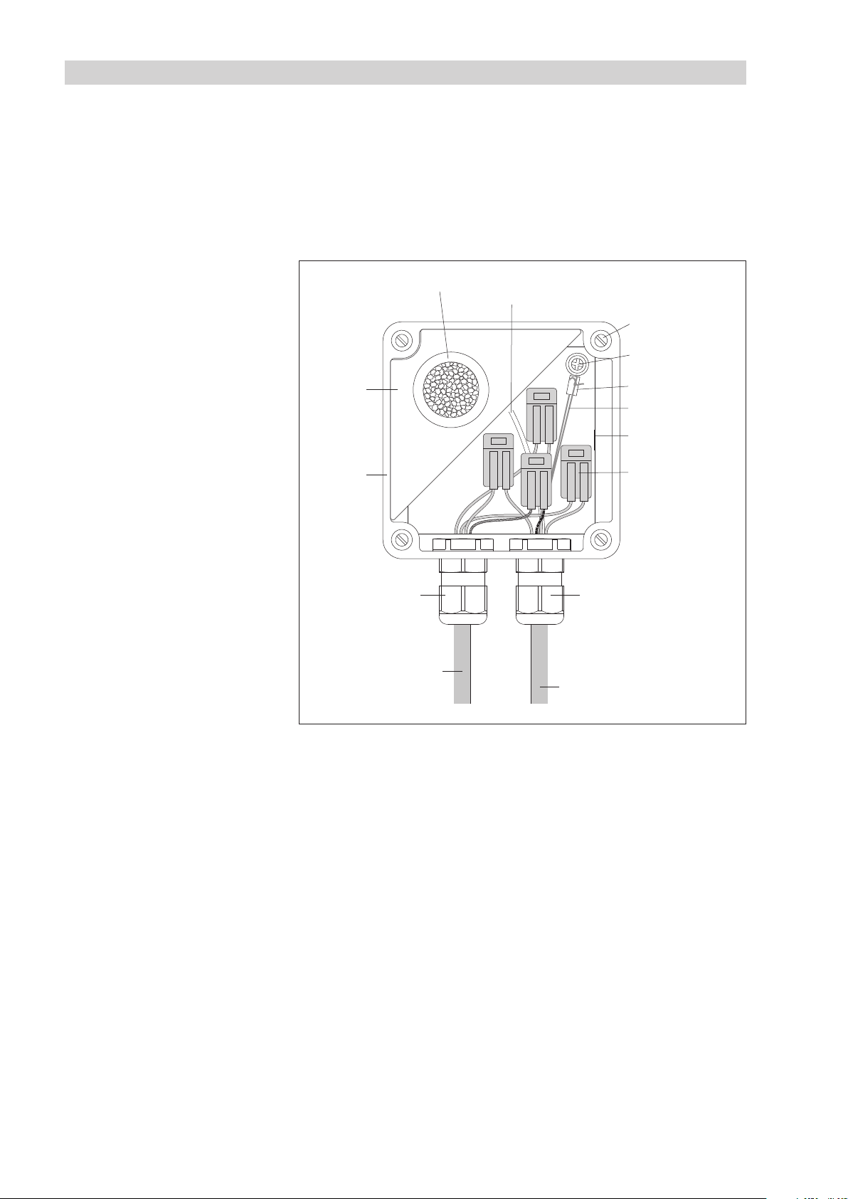
The OTT FAD 5 humidity absorbing system accessory for the OTT PLS pressure
probe fulfills various functions:
䊳 drying the air that has entered the pressure compensation capillary;
䊳 connecting the pressure probe cable with a connection cable to the data -
logger/electrical supply via several two-pin connectors;
䊳 with short pressure probe cables (< 5 m): it can be used as a fixing point
to hang the OTT PLS.
Fig. 15: Installing the OTT FAD 5
humidity absorbing system.
(Housing lid has been removed.)
30
Requirements of the installation location
䊳 The installation location must be protected from humidity as effectively as possible.
䊳 If the installation location is in a control cabinet: There must be a pressure com-
pensation possibility to the surroundings (no hermetically sealed closure)!
䊳 Installation position only as shown in Figure 15.
䊳 OTT FAD 5 to be used as a fixing point: Attach the humidity absorbing
system over the station so that the pressure probe hangs freely (cable length
OTT PLS < 5 m).
Fasten the OTT FAD 5 as follows:
䡵 Unscrew the four captive screws on the housing lid and remove it.
䡵 Secure the humidity absorbing system on a solid surface with four screws.
Hole spacing: 79 mm. (Select screws appropriate to the material: e. g. wood
screws with plugs, machine screws with nuts, Ø 4 mm.)
Page 31

How to connect the cable to the OTT FAD 5:
Caution:
䊳 Only remove the transport protection for the pressure probe cable immediately
before connecting!
䊳 Do not damage the pressure compensation capillary, do not block it, and protect
it from contamination and humidity!
䡵 Feed the pressure probe cable through a cable gland on the OTT FAD 5.
䡵 Only if the OTT FAD 5 is used as the fixing point for hanging the OTT PLS:
secure ring terminal with the Phillips screw and put the pressure probe cable
under tension.
䡵 Tighten the cable gland firmly by hand.
䡵 Remove approx. 80 … 100 mm of the insulation of the datalogger connection
cable/electrical supply.
䡵 Feed the connection cable through the second cable gland on the OTT FAD 5
and tighten the cable gland firmly by hand.
䡵 Connect the wires of both cables with each other appropriately: To do this,
ompletely open the connectors (raise orange lever by approx. 90 °), insert
c
wires with 10 mm insulation removed, close lever. Size range 0.08 … 2.5 mm
Fine-wired conductors do not require end sleeves. For wire allocation, see
sticker on the housing lid of the OTT FAD 5.
How to insert the dessicant cartridge and check it:
2
.
䡵 Insert the dessicant cartridge into the shaped foam part. The coloured indicator
must be orange!
䡵 Immediately replace the housing lid and secure with the four captive screws.
䡵 C
heck the colour of the coloured indicator at regular intervals.
The intervals are heavily dependent on the atmospheric humidity present.
Recommendation: after initial installation, check at monthly intervals. Afterwards
the intervals can be adapted to the local conditions. Take seasonal climate
changes into account.
䡵 Follow the directions on the slip enclosed with the dessicant cartridge to regen-
erate the dessicant cartridge.
Information on the functional principle of the dessicant cartridges:
The air entering the humidity absorbing system through an air-permeable membrane in the side wall of the OTT FAD 5 is dried by the dessicant cartridge. This
prevents humid air from entering the pressure compensation capillary as a result
of temperature and air variations. Humidity could block the pressure compen sation capillary due to the formation of condensation and lead to inaccurate
measurement results.
The dessicant cartridge contains silica gel with a coloured indicator. It has the
property of extracting water from the surrounding air and is therefore used for
drying air that is contained in a device. Due to the coloured indicator, the silica
gel is orange when dry and white when wet. Once the silica gel has become
white, it can no longer keep the air dry and must be exchanged for a dessicant
cartridge with orange silica gel.
31
Page 32
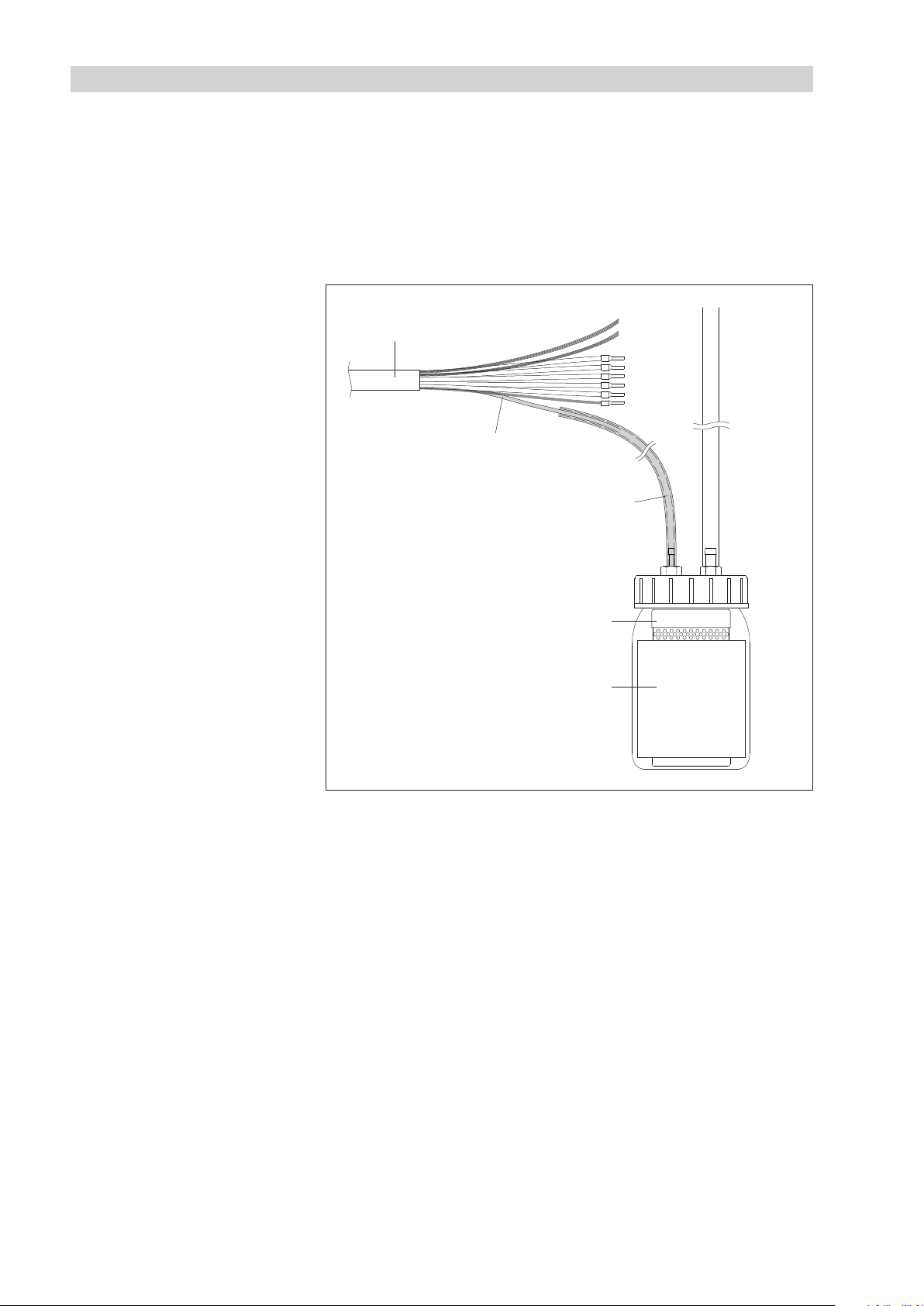
Appendix D – Installing the OTT FAD 4PF humidity absorbing system
Pressure probe cable
Pressure compensation capillary
Humidity absorbing system OTT FAD 4PF
Dessicant cartridge
PVC tube
(Ø 4/2 mm)
The OTT FAD 4PF humidity absorbing system dries the surrounding air that enters
the pressure compensation capillary.
䡵 Mount the humidity absorbing system at the driest position possible (e.g. with
double-sided tape). If this is in a control cabinet, it is important that there is a
pressure compensation possibility to the outside (no hermetically sealed closure!).
䡵 Insert the pressure compensation capillary at least 5 cm into the PVC tube of
the humidity absorbing system as shown in Figure 16.
Fig. 16: Installing the OTT FAD 4PF
humidity absorbing system.
32
䡵 Please note the instruction leaflet enclosed with the OTT FAD 4PF for regen -
erating the desiccant cartridge.
Page 33

Appendix E – Note on Declaration of Conformity
If necessary, you can download the current version of the Declaration of Con formity of the OTT PLS from our website as a PDF file: „www.ott.com/resources“!
33
Page 34

Page 35

Page 36

Document number
63.037.001.B.E 08-0818
OTT Hydromet GmbH
Ludwigstrasse 16
87437 Kempten · Germany
Phone +49 831 5617-0
Fax +49 831 5617-209
[email protected] · www.ott.com
 Loading...