

Page 1
Operating instructions
Groundwater Datalogger
OTT Orpheus Mini
English
Page 2

These operating instructions (version "06-0311") cover the OTT Orpheus Mini
software versions
OTT Orpheus Mini firmware: from V 1.41.0
OTT Orpheus Mini operating program: from V 1.52.0
The OTT Orpheus Mini firmware version can be found in the "Advanced operation" mode, "OTT Orpheus Mini" window of the operating program. The version
of the operating program can be found via the "Info" function in the "Help" menu.
We reserve the right to make technical changes and improvements without notice.
Page 3

Table of contents
1 Scope of supply 4
2 Order numbers 4
3 Basic safety information 5
4 Introduction 6
5 Installing, checking, and exchanging batteries 8
6 Installing the OTT Orpheus Mini 10
6.1 Installing in 1" observation wells 12
6.2 Installing in 2", 3", 4", 5" or 6" observation wells,
top cap with adapter plate recess 13
6.3 Installing in observation wells beginning at 2" diameter,
top cap without adapter plate recess 15
6.4 Installing in observation wells beginning at 2" diameter without a top cap 17
7 Adjusting the OTT Orpheus Mini operating parameters 18
7.1 Installing the OTT Orpheus Mini operating program 18
7.2 Setting up the PC/OTT Orpheus Mini communication link 18
7.3 Adjusting the OTT Orpheus Mini operating parameters 20
7.4 Storing/loading the OTT Orpheus Mini configuration 22
7.5 Importing/exporting the OTT Orpheus Mini configuration 23
8 Determining and displaying instantaneous values (observer function) 25
9 Downloading data 27
10 Exporting data 28
11 Displaying data 29
12 Protecting the OTT Orpheus Mini and OTT Orpheus Mini
operating program with a password 30
13 Date and time settings 32
14 Deleting the data memory 33
15 Updating the OTT Orpheus Mini firmware 33
16 Maintenance work 34
16.1 Cleaning the pressure probe 34
16.2 Replacing the desiccant capsules 35
16.3 Checking/replacing the batteries 35
17 Error messages 36
18 Troubleshooting/fault correction 36
19 Repair 37
20 Note about the disposal of old units 37
21 Technical data 38
Appendix A – Declaration of conformity OTT Orpheus Mini 40
3
Page 4

4
1 Scope of supply
– 1 groundwater datalogger consisting of a communication unit with installed
O-ring, pressure probe cable with pressure compensation capillary and
Kevlar cores for longitudinal stabilization, 2 desiccant capsules, pressure
probe with datalogger
– 3 x 1.5 V batteries, alkaline (LR6 · AA) or lithium design (FR6 · AA)
– 1 Brief instructions
– 1 factory acceptance test certificate (FAT)
2 Order numbers
Groundwater datalogger 55.440.002.3.2
Required ordering information
– Measuring range: 0 … 4 m;
0 … 10 m;
0 … 20 m;
0 … 40 m;
0 … 100 m
– System length: 1,5 … 200 m (±1 % ±5 cm)
– Battery type: alkaline, lithium
– Temperature sensor: calibrated/uncalibrated
Accessories Installation kit 55.440.025.9.2
consisting of: Adapter ring 1", adapter
plates 2", 4", 6", suspension bracket
Adapter plates 3" and 5" 55.440.444.4.1
Suspension brackets 55.440.450.4.1
for top caps starting at 2" without recess and
for universal installation
Cable suspension unit on request
for OTT Orpheus Mini system lengths of > 100 m
CD-ROM "OTT Orpheus Mini Software" 56.552.000.9.7
OTT Orpheus Mini operating program for PC and
OTT Orpheus Mini operating instructions in PDF format
Top cap
with integrated fastening hook
– for 2" observation wells 24.220.052.9.5
– for 4" observation wells 24.220.054.9.5
– for 6" observation wells 24.220.057.9.5
Intelligent top cap OTT ITC 55.530.0XX.3.2
for GSM remote data transfer
5-sided key 20.250.095.4.1
for locking OTT top caps
Optical OTT Duolink reading head 55.520.017.4.2
Optical reading head OTT IrDA link USB 55.520.026.9.2
OTT Orpheus Mini operating instructions 55.440.002.B.D
Alkaline battery 96.800.004.9.5
LR6 · AA; 3 x required
Lithium battery 97.800.008.9.5
FR6 · AA; 3 x required
Desiccant capsules 97.100.280.9.5
2x in aluminum bags
OTT Orpheus Mini
OTT Orpheus Mini
Replacement parts/
Consumable materials
Page 5
5
3 Basic safety information
Read these operating instructions through before using the OTT Orpheus Mini
for the first time! Make yourself completely familiar with the installation and
operation of the OTT Orpheus Mini and its accessories! Retain these operating
instructions for later reference.
The OTT Orpheus Mini is used to measure groundwater levels and the water
temperature of the groundwater. Only use the OTT Orpheus Mini as described
in these operating instructions!
For further information, ➝ see Chapter 4, "Introduction".
Note all the information on safety and warnings given within the individual
work steps. All safety information and warnings in these operating instructions
are marked with the adjacent warning signals:
– Black warning triangle ➝ warning of possible damage to device,
reduced functionality and particularly noteworthy points.
– Black warning triangle with yellow background ➝ there is a
health hazard! Detailed information on the hazard with information on how
to prevent the hazard and possible consequences of non-observance.
Ensure the electrical, mechanical, and climatic specifications listed in the
technical data are adhered to.
For further information ➝ see Chapter 21, "Technical data".
Handle the pressure probe cable carefully: Do not kink the cable or pull it
across sharp edges!
Do not make any changes to or retrofit the OTT Orpheus Mini! If changes or
retrofits are made, all guarantee claims are voided.
Have a faulty OTT Orpheus Mini inspected and repaired by our repair center.
On no account carry out repairs yourself!
For further information ➝ see Chapter 19, "Repair".
Dispose of the OTT Orpheus Mini properly after taking out of service. On
no account put the OTT Orpheus Mini into the normal household waste.
For further information ➝ see Chapter 20, "Notes about the disposal of
old units".
Page 6

6
4 Introduction
The OTT Orpheus Mini groundwater datalogger provides precise measurement
and recording of groundwater levels and temperatures.
The pressure probe equiped with a relative pressure measuring cell uses the
hydrostatic pressure of the water column to determine the water level. A pressure
compensation capillary in the pressure probe cable gives the measuring cell the
current ambient air pressure as a reference. Erroneous measurement results due
to atmospheric air pressure fluctuations are thus eliminated.
The OTT Orpheus Mini is available with five measuring ranges:
0 … 4 m water column (0 ... 0.4 bar)
0 … 10 m water column (0 ... 1 bar)
0 … 20 m water column (0 ... 2 bar)
0 … 40 m water column (0 ... 4 bar)
0 … 100 m water column (0 ... 10 bar)
With the help of a reference value that is input during startup, the OTT Orpheus
Mini's standard setting provides measurement results in the form of depth values.
Alternatively, levels or pressure values are possible. The measurement intervals
(sample intervals) can be preselected as necessary.
The operating parameters are adjusted with the "OTT Orpheus Mini operating
program" PC software. This software allows the system to be conveniently and
flexibly tailored to a wide range of measurement requirements of a station. The
software can be set to provide a basic or an advanced operator interface. The
basic operator interface allows all settings to be adjusted within a single program
window. In the advanced operator interface, the sample interval can be controlled through limit events, for example. The software also supports the execution
of pump tests.
The stored measured values are made available through an infrared interface
(IrDA) for wireless readout by a PC with OTT Orpheus Mini operating program or
OTT Hydras 3 or by a PDA with OTT Hydras 3 Pocket.
Together with an OTT ITC intelligent top cap (accessory), remote data transfer
and remote parameter input is possible via the GSM mobile telephone network
(GSM = global system for mobile communications). The remote data transfer can
be optionally carried out by SMS text messages or using the packet oriented
mobile radio transmission service GPRS (general packet radio service).
The OTT Orpheus Mini is installed simply by hanging it in observation wells of 1"
in diameter and above. Various adapters/suspension brackets are available as
accessories for this purpose. Three 1.5 V lithium batteries (type AA) provide an
operating life of over five years (sample interval: 1 hour; system length: 50 m).
Alternatively, alkaline batteries with a limited working life can be used.
The communication unit of the OTT Orpheus Mini can withstand temporary flooding (for details, see Chapter 21, "Technical data").
Page 7
7
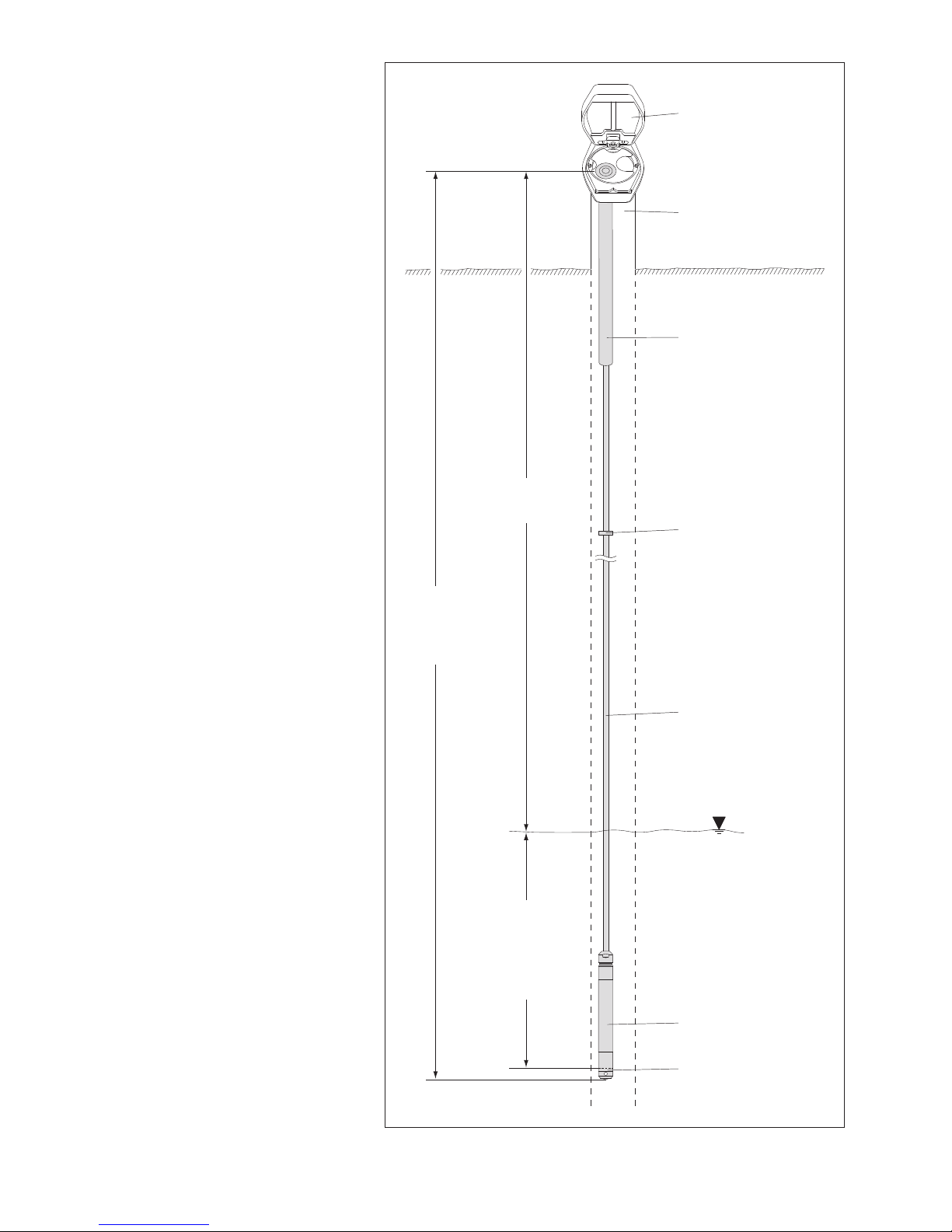
Fig. 1: Setup of a groundwater measure-
ment station with the OTT Orpheus Mini.
The OTT Orpheus Mini essentially consists
of three components: communication unit,
pressure probe cable and pressure probe
with datalogger.
OTT Orpheus Mini system length = length of
communication unit + cable length + length
of pressure probe with datalogger. (The
system length is required when ordering
an OTT Orpheus Mini. When setting the
OTT Orpheus Mini operating parameters
the system length is not required.)
(The rubber stop attached to the pressure
probe cable prevents the pipe casing from
falling when the communication unit is
open. Do not move the rubber stop!)
Top cap
Observation well
Communication unit
Pressure probe cable
Rubber stop
Pressure probe
with datalogger
Pressure sensor
DepthMeasuring range
Measuring ranges:
0 … 4 m, 0 … 10 m, 0 … 20 m,
0 … 40 m, 0 … 100 m water column
System length
Page 8
8
5 Installing, checking and replacing batteries
Please note
Only use the battery types specified (no rechargeable types).
Always use brand new batteries. Do not mix used and new batteries.
Do not mix batteries from different manufacturers.
Do not mix lithium and alkaline batteries.
Properly dispose of dead batteries. Do not put in household waste.
Suitable battery types
3 x 1.5 V AA cells (LR6/FR6),
alkaline or lithium design (LiFeS; Energizer L91)
Insert the batteries as follows
Slide the pipe casing of the communication unit approximately 30 cm in the
direction of the pressure probe cable.
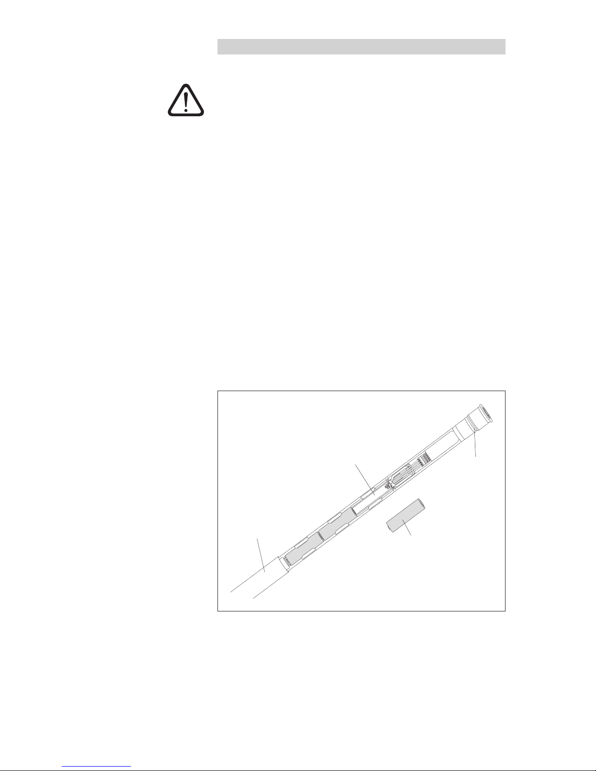
Insert 3 batteries (LR6/FR6 · AA) in the battery compartment as shown in
Figure
2. Ensure that the polarity is correct!
Slide the pipe casing of the communication unit back on until it stops.
Notes
The OTT Orpheus Mini begins measurements within a few seconds of the
batteries being inserted (there is no on/off switch).
If the OTT Orpheus Mini is to be taken out of service ➝ remove the batteries.
This will prevent the batteries from draining prematurely and will stop any
recording of unusable measurements.
When bringing back into operation it takes – dependent on how much data is
stored – up to 7 minutes before the OTT Orpheus Mini begins measurements
again.
Fig. 2: Installing batteries.
Communication unit
pipe housing
Battery compartment
LR6/FR6 · AA
battery
Backstop
+
+
+
Page 9

9
Battery lifetime
With a sample interval of 1 hour and 50 m system length (without OTT ITC)
Lithium batteries: at least 5 years
Alkaline batteries: at least 1.5 years (high quality battery types)
Note
At 0 °C, alkaline batteries drop to approximately 50 % of their original 20 °C
capacity and at –10 °C they drop to approximately 35 % due to their design.
If temperatures drop below 0 °C at the measurement station, it is recommended
that lithium batteries be used.
Check the battery voltage as follows
Set up the PC/OTT Orpheus Mini communication link (see Chapter 7.2).
Select the "OTT Orpheus Mini" menu, "View Instantaneous values" function
1)
➝ the OTT Orpheus Mini starts an instantaneous value measurement ➝ the
"Observer" window indicates the current battery voltage and the energy
consumed from the batteries so far in Ah.
If the battery voltage is ≤ 3.5 to 3.6 volts ➝ replace the batteries.
Click on the "Exit" button.
Close the operating program.
1)
If set appropriately (Menu "File", function "Options"), the operating program starts at the
same time the "Observer" window is opened.
Replace dead batteries as follows
Open the top cap/observation well cover.
Pull the communication unit approximately 80 cm out of the observation well
and hold (a second person would be useful).
Slide the pipe casing of the communication unit approximately 30 cm in the
direction of the pressure probe cable. (The rubber stop located on the pressure
probe cable (see Fig. 1) prevents the pipe casing from falling. Do not move the
rubber stop!)
Remove dead batteries.
Insert 3 new batteries (LR6/FR6 · AA) into the battery compartment as shown
in Figure 2 within 10 minutes. Ensure that the polarity is correct!
Slide the pipe casing of the communication unit back on until it stops.
Slowly and carefully replace the communication unit in the observation well.
Close the top cap/observation well cover.
Notes
The OTT Orpheus Mini stores the measured values in a non-volatile memory.
There is no loss of data when changing batteries.
This also applies to storage without batteries over a long timespan.
If it takes longer than approx. 10 minutes to replace dead batteries, the time
(and possibly the date) will have to be re-entered (see Chapter13, "Date and
time settings"). Furthermore, it takes – dependent on how much data is stored –
up to 7minutes until the OTT Orpheus Mini begins measurement again.
When replacing the batteries, we recommend changing the desiccant capsules
at the same time (see Chapter 16.2, "Replacing the desiccant capsules").
Page 10
10
6 Installing the OTT Orpheus Mini
System length up to 100 meters
The installation of the OTT Orpheus Mini is carried out by suspending it in the
observation well. The necessary accessories and type of installation varies
depending on the diameter of the observation well and the design of the top cap:
1" observation wells see 6.1
2", 4", or 6" observation wells, see 6.2
OTT top caps with recess for adapter plate
Observation wells beginning at 2" in diameter, see 6.3
Top caps without recess for adapter plate
Special case: observation wells beginning at 2" in
diameter without top cap, see 6.4
System length over 100 meter
For installation of an OTT Orpheus Mini with a system length of more than
100meters, there is a special cable suspension unit available (see accessories).
This suspension unit is described separately.
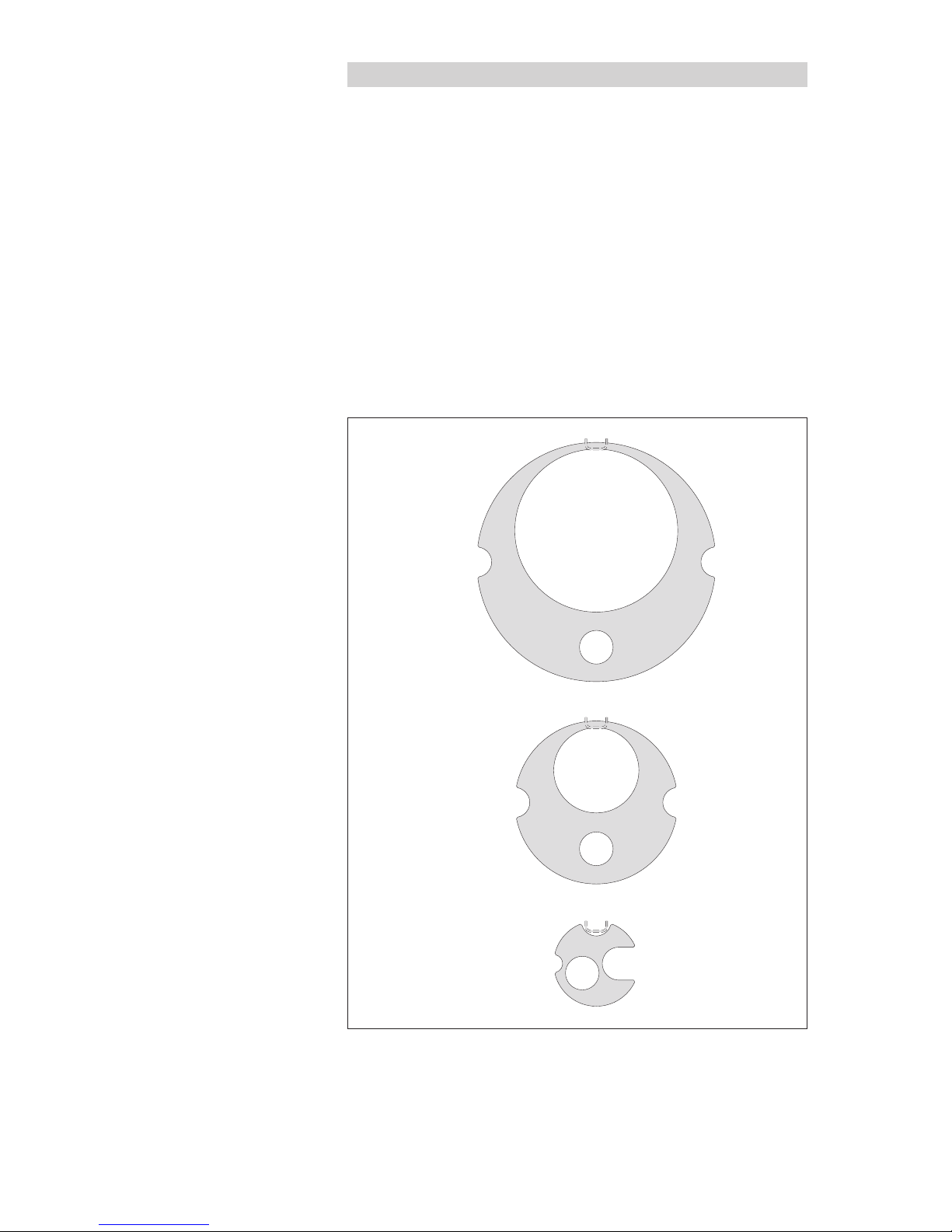
Fig. 3: Installation accessories – Part 1.
1 = hole for OTT Orpheus Mini
2 = hole for contact gauge
3 = recess for screws on the top cap
Adapter plate 2"
Adapter plate 4"
Adapter plate 6"
2
3
33
32/3
3
1
1
2
1
Page 11
11
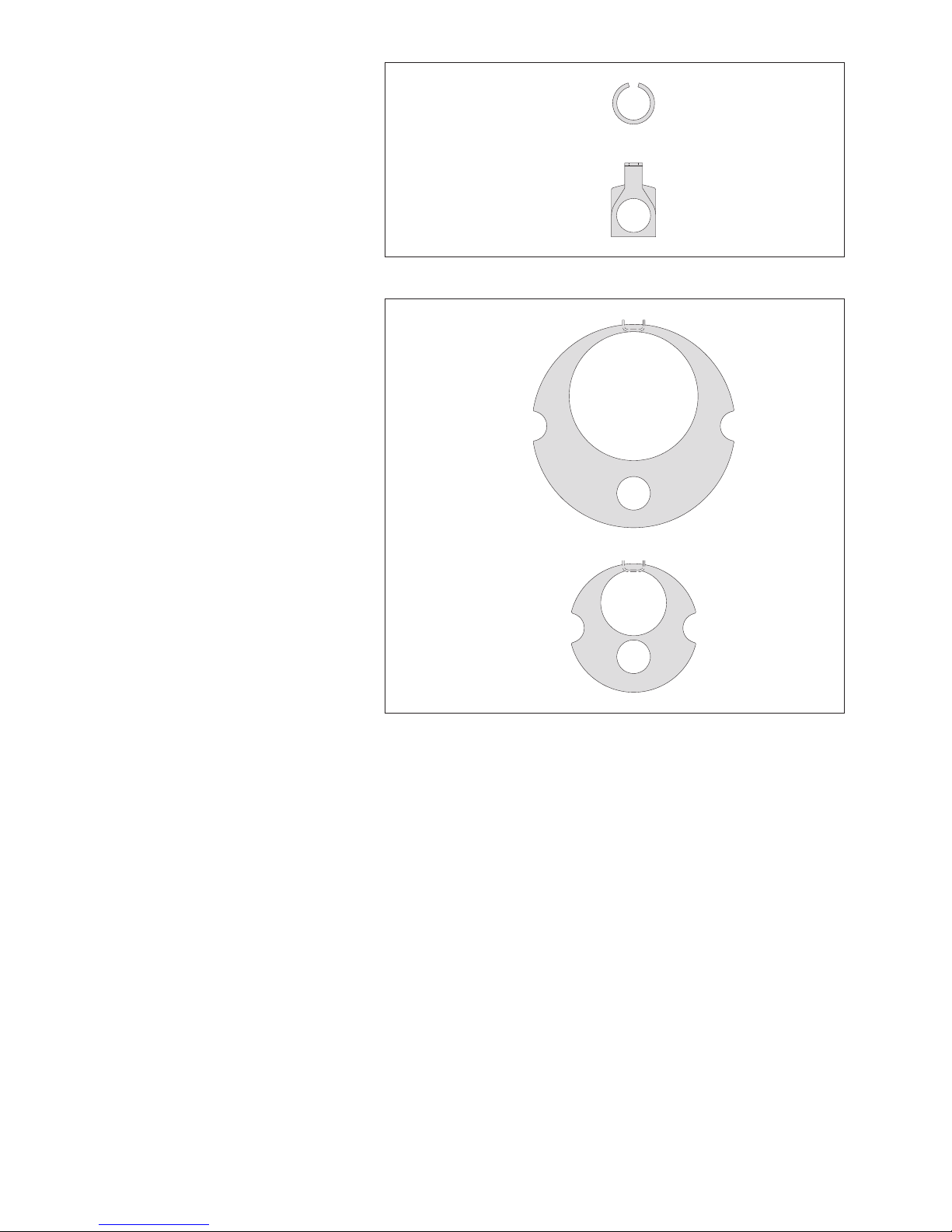
Fig. 4: Installation accessories – Part 2.
Fig. 5: Accessory adapter plates 3" and 5".
1 = hole for OTT Orpheus Mini
2 = hole for contact gauge
3 = Recess for screws on the top cap
Suspension bracket
Adapter ring 1"
A
Adapter plate 3"
Adapter plate 5"
33
33
1
1
2
2
Page 12
12
6.1 Installing in 1" observation wells
Required accessories: Adapter ring for 1" observation wells.
Install the OTT Orpheus Mini as follows
Preliminary work: If not already done, install batteries
(see Chapter 5).
Open the observation well cover.
Determine the current depth with a contact gauge and make a note of it.
Slide O-ring from the communication unit onto the pressure probe cable.
Place adapter ring over the pressure probe cable and slide it until it comes
to rest against the communication unit.
Slide O-ring back onto the communication unit.
Feed the pressure probe into the observation well.
Slowly and carefully lower the pressure probe with the pressure probe
cable!
Feed the communication unit into the observation well until the O-ring sits
on the observation well (see Figure 6).
Set operating parameters (see Chapter 7).
Close the observation well cover carefully. Caution: Do not damage the
infrared interface (maintain correct spacing)!
Fig. 6: Installing the OTT Orpheus Mini
in 1" observation well.
Adapter ring 1"
O-ring
Communication unit
Observation well
cover (example)
Infrared interface
1" observation well
Page 13
13
6.2 Installing in 2", 3", 4", 5" or 6" observation wells,
top cap with adapter plate recess
Required accessories: OTT top cap with appropriate sized recess and
the matching adapter plate.
Install the OTT Orpheus Mini as follows
Preliminary work: If not already done, install batteries
(see Chapter 5).
Open the top cap cover.
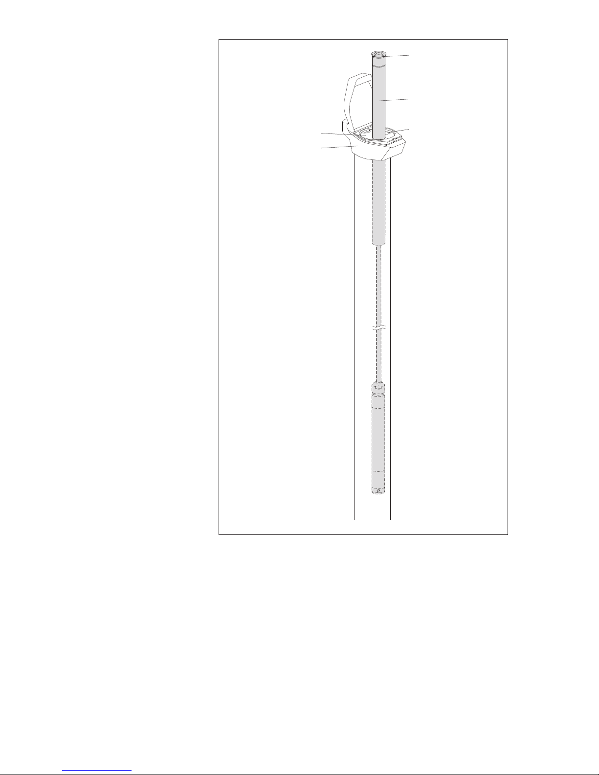
Insert correctly sized adapter plate into top cap.
Pass pressure probe through the hole in the adapter plate.
Slowly and carefully lower the pressure probe into the observation
well with the pressure probe cable (see Fig. 7).
Pass the communication unit through the hole in the adapter plate until
the O-ring sits on the adapter plate (see Fig. 7).
Determine the current depth with a contact gauge and make a note of it.
Set operating parameters (see Chapter 7).
Close the top cap.
Fig. 7: Installing the OTT Orpheus Mini in
2", 3", 4", 5" or 6" observation wells.
Example: 2" observation well
Adapter ring 2"
Communication
unit
Recess
O-ring
OTT top cap
Page 14
14
Fig. 8: Installing the OTT Orpheus Mini.
Recess
Top cap
Communication unit
O-ring
Adapter plate
Page 15
15
6.3 Installing in observation wells beginning at 2" in diameter,
top cap without adapter plate recess
Required accessories: Top cap with attachment screw for the upper part of the
top cap. Suspension bracket.
Install the OTT Orpheus Mini as follows
Preliminary work: If not already done, install batteries
(see Chapter 5).
Open the top cap cover.
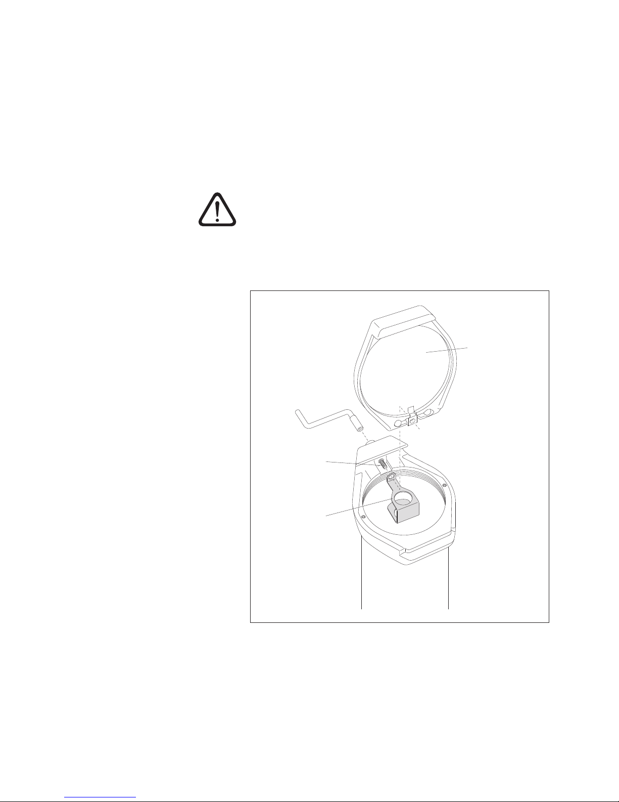
Remove the upper part of the top cap (see Fig. 9).
Place the suspension bracket on the screw (see Fig. 9).
Reattach the upper part of the top cap (see Fig. 9).
Pass the pressure probe through the holes in the suspension bracket.
Slowly and carefully lower the pressure probe into the observation well
with the pressure probe cable.
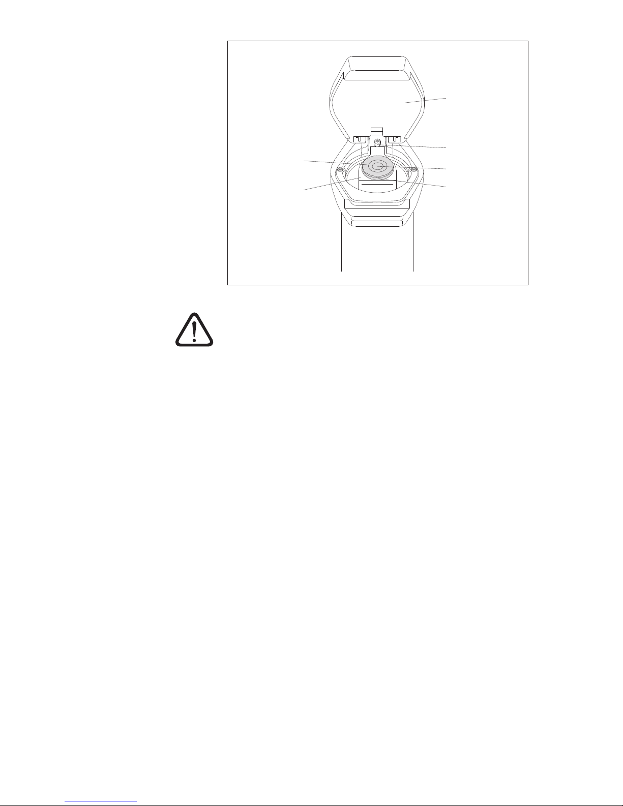
Pass the communication unit through the holes in the suspension bracket until
the O-ring sits on the suspension bracket (see Fig. 10).
Determine the current depth with a contact gauge and make a note of it.
Set operating parameters (see Chapter 7).
Close the top cap.
Suspension
bracket
Screw
Top cap
upper part
Fig. 9: Installing the suspension bracket in
observation wells beginning at 2" diameter
with a top cap without a recess.
Example: 4" observation well
Page 16
16
Caution: For top caps with installed suspension brackets, never completely
remove the screw in the top cap! Otherwise, the suspension bracket and the
OTT Orpheus Mini will fall into the observation well!
Fig. 10: Installing the OTT Orpheus Mini in
observation wells beginning at 2" diameter
with a top cap without a recess.
Example: 2" observation well
O-ring
Suspension
bracket
Communication
unit
Top cap
upper part
Screw
Infrared
interface
Page 17
17
6.4 Installing in observation wells beginning at 2" diameter
without a top cap
For this installation case, an individual solution to fasten the OTT Orpheus Mini
must be found depending on the measurement station. Example: fix a suspension
bracket with an M6 Allen bolt/nut laterally at the upper end of the observation well.
Required accessories: suspension bracket, for example: M6 Allen bolt, washer
and M6 hex nut (all in stainless steel).
Install the OTT Orpheus Mini as follows (example)
Preliminary work: If not already done, install batteries
(see Chapter 5).
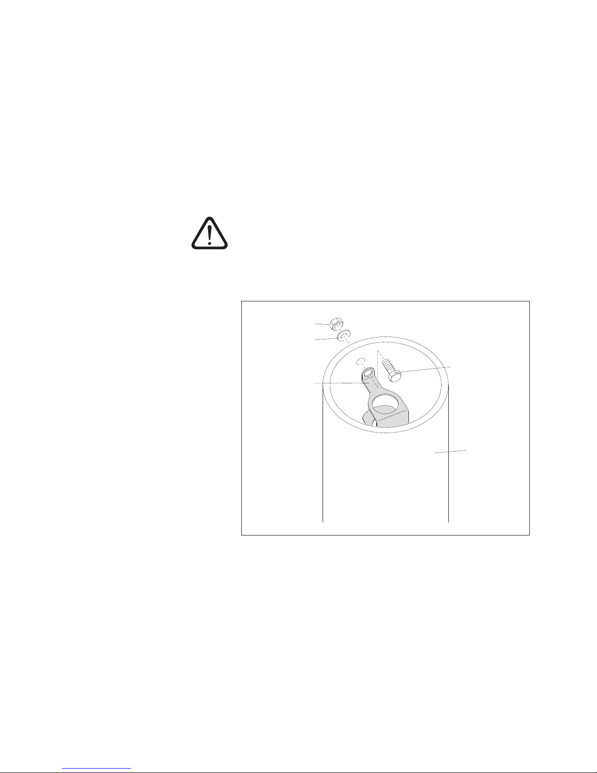
Make a hole (Ø 6.5 mm) laterally at the upper end of the observation well.
Attach the suspension bracket to the observation well with an M6 Allen bolt,
washer and M6 hex nut (see Fig. 11).
Pass the pressure probe through the holes in the suspension bracket.
Slowly and carefully lower the pressure probe into the observation well
with the pressure probe cable.
Pass the communication unit through the holes in the suspension bracket until
the O-ring sits on the suspension bracket (see Fig. 10).
Determine the current depth with a contact gauge and make a note of it.
Set operating parameters (see Chapter 7).
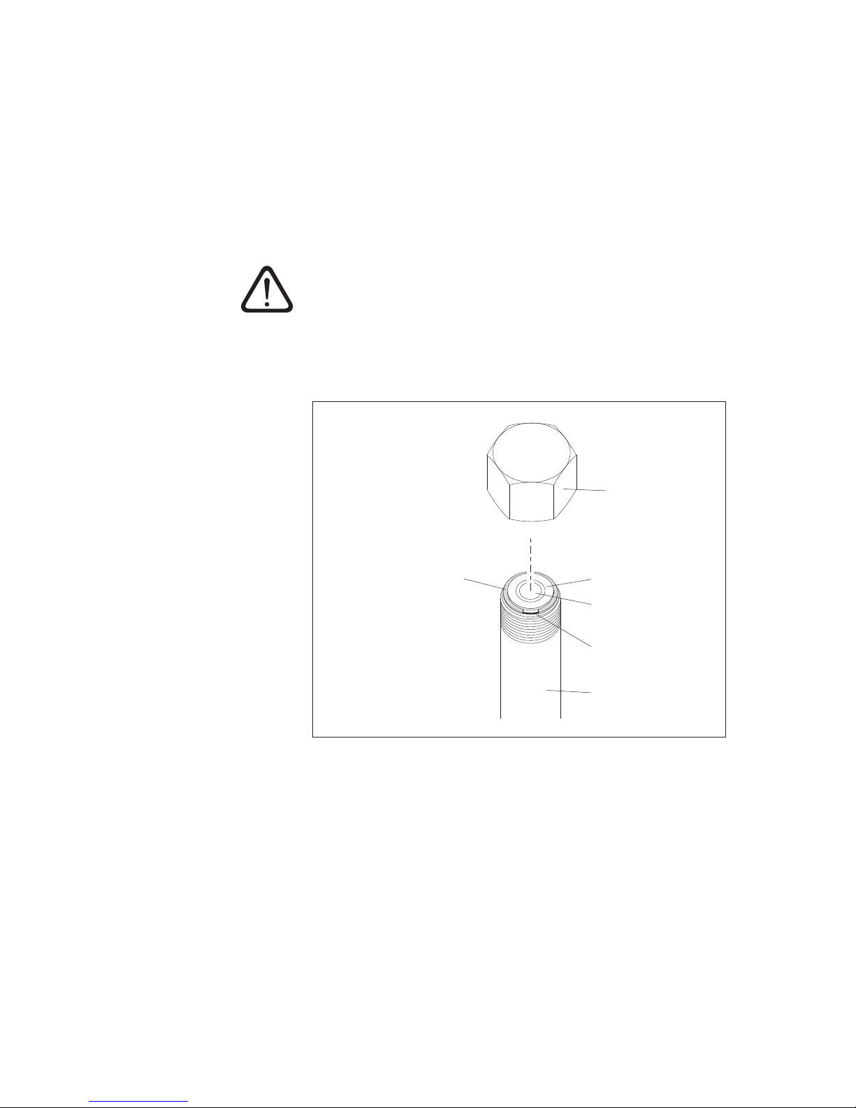
Fig. 11: Example installation of an
OTT Orpheus Mini in an observation
well beginning at 2" diameter.
Proceed similarly for other local conditions!
Suspension
bracket
Hex nut
Washer
Allen bolt
Observation
well
Page 18

18
7 Adjusting the OTT Orpheus Mini operating
parameters
To adjust the OTT Orpheus Mini operating parameters, you will need the
"OTT Orpheus Mini operating program" (WBSPL0.exe) PC software. This software
is contained on the "OTT Orpheus Mini software" CD-ROM (accessory).
Hardware and software requirements: see CD insert.
7.1 Installing the OTT Orpheus Mini operating program
Install the OTT Orpheus Mini operating program as follows
Insert the OTT Orpheus Mini software CD-ROM into the drive of the PC.
Start the "setup.exe" file in the "\Software\English"
1)
directory (e.g. double
click on the file symbol) ➝ the Setup Assistant opens and guides you through
the installation.
Follow the installation instructions on the screen.
1)
Alternatively: "\Deutsch" or "\Français" or "\Español"
7.2 Setting up the PC/OTT Orpheus Mini communication link
In the following chapters, establishing a communication connection between the
OTT Orpheus Mini and a PC is a pre-requisite for the subsequent steps. The following description illustrates the various methods of setting up this communication link.
The communication between the OTT Orpheus Mini and a PC is established wirelessly using invisible infrared light (IrDA interface).
Required accessories:
OTT Duolink reading head
1)
or
OTT IrDA-Link USB reading head
1)
with PCB version "b": see label on the connection line
Note
Together with a modem and the OTT ITC intelligent top cap, it is possible to
establish a remote communication connection. See online help for the OTT
Orpheus Mini operating program.
How to establish a communication link
Start the OTT Orpheus Mini operating program.
Change the language for the OTT Orpheus Mini operating program as
required: press function key "F3" (multiple times) until the required language
appears.
In the start window, press the "Setup device" button ➝ the operating program
displays the "Basic operation" window. No operating parameters for the OTT
Orpheus Mini are visible yet.
– Setting up a communication link with the OTT Duolink reading head:
Connect the OTT Duolink reading head to a serial PC port (COM1, etc.).
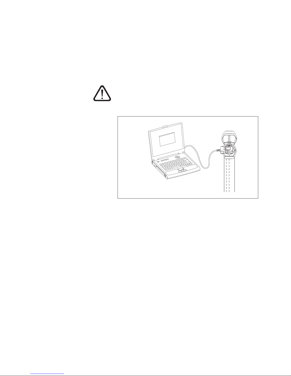
Direct the OTT DuoLink reading head at the OTT Orpheus Mini infrared
interface (see Fig. 12).
In the OTT Orpheus Mini operating program, select the communication path
"IrDA – OTT DuoLink" and the serial port used (COM1, ...).
Page 19
19
– Setting up a communication link with the OTT IrDA-Link USB reading head:
Connect the OTT IrDA-Link USB reading head to a USB port on the PC. (USB
interface drivers must be installed – see separate installation instructions.)
Place the OTT IrDA-Link USB reading head on the OTT Orpheus Mini
infrared interface (see Fig. 12).
Select the communication path "IrDA – OTT IrDA-Link" in the OTT Orpheus
Mini operating program.
Notes
The integrated infrared interface of a PC (standard for many notebooks) can
only be used with the Windows 95 and Windows NT operating systems!
The OTT Orpheus Mini infrared interface has a radiation angle of approx. ±15 °.
Caution: OTT Orpheus Mini connected to OTT ITC: Establishing a communication connection can take up to a minute! (This is always the case if the OTT
Orpheus Mini attempts to communicate with the OTT ITC (e.g. SMS message)
and the OTT ITC is open at the time.)
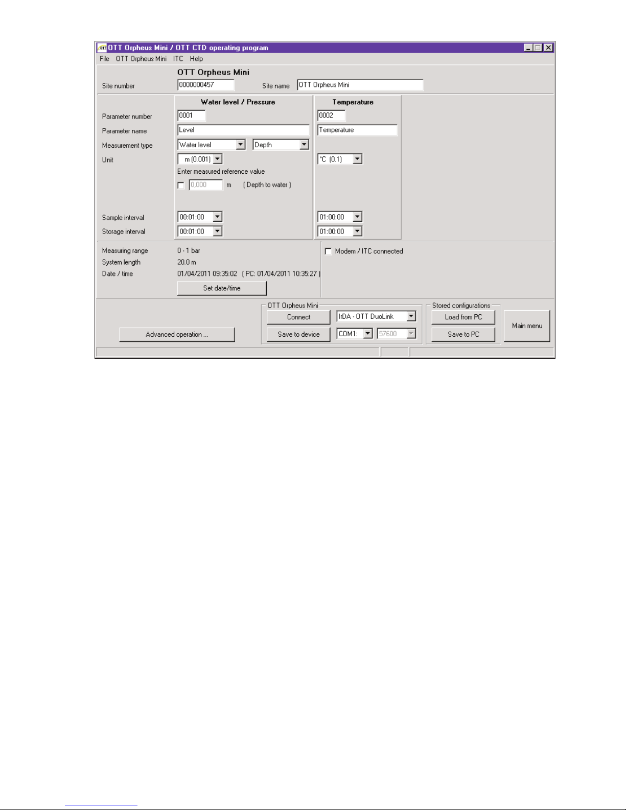
7.3 Adjusting the OTT Orpheus Mini operating parameters
How to set the OTT Orpheus Mini operating parameters
Click the "Connect" button (alternatively: menu "OTT Orpheus Mini", function
"Connect") ➝ the operating program reads the current operating parameters
of the OTT Orpheus Mini.
Adjusting operating parameters (see pages 21/22).
If necessary: "Set up cyclical data transfer using SMS messages in combination
with the intelligent top cap OTT ITC" or "Set up cyclical data transfer using
GPRS in combination with the intelligent top cap OTT ITC" (see page 20).
Fig. 12: Establishing a communication
link PC/OTT Orpheus Mini.
Page 20

20
Set date/time: adjust the proposed PC date/time or individually set date/time
using "Set date/time" (see also Chapter 13).
Caution: The operating program automatically corrects any summer time PC
adjustments.
Click the "Connect" button ➝ "Warning: Reset the OTT Orpheus Mini and
delete data memory additionally?" Confirm with "Yes" (recommended for initial
installation and reinstallations).
Caution: All measured values collected until now will be permanently lost!
Check the level of the measured value set (pressure sensor). See Chapter 8.
Remove the OTT DuoLink.
Close the top cap/observation well cover.
If required: Set up cyclical data transfer with SMS text message in
combination with an OTT ITC intelligent top cap
1)
Activate check box "Modem/ITC connected".
Activate check box "SMS data transmission active".
If necessary: Activate the "Authorize Roaming" check box and/or "Store GSM
signal strength".
Click on the "Settings ITC" button ➝ the operating program starts an Assistant
for setting all the necessary operating parameters.
Enter the receiver phone no. for the data SMS. (phone number of a large
account or for a PC with GSM modem.)
Click on the "Next" button.
If necessary: enter SIM PIN (4-digit) of the SIM card.
Click on the "Next" button.
Set or enter the SMS-C phone no. of the network operator. (Phone number of
the SMS service center. The SMS-C phone number is normally already saved
on the SIM card ➝ in this case, set to "SIM card".)
Click on the "Next" button.
Select the mode of SMS transmission.
Click on the "Next" button.
Set the interval for transmission of the storage values.
Click on the "Next" button.
Set the offset time for the transmission interval.
Click on the "Exit" button.
Check the settings afterwards and correct as necessary.
Click on the "OK" button.
If required: Set up cyclical data transfer using GPRS in combination
with an OTT ITC intelligent top cap
1)
Activate check box "Modem/ITC connected".
Activate check box "GPRS data transmission active".
If necessary: Activate the "Authorize Roaming" check box and/or "Store GSM
signal strength".
Click on the "Settings ITC" button ➝ the operating program opens a window
with several tabs for setting all the necessary operating parameters.
Make the required settings in the "General", "Operator", "FTP" and "Time sync."
tabs. Caution: The SIM PIN for the SIM card used should be deactivated!
Otherwise enter the SIM PIN for advanced operation in the "Modem/ITC" tab.
Click on the "OK" button.
1)
For further information, refer to the online help
Page 21
21
OTT Orpheus Mini
Site number station number, 10 characters (alphanumeric)
Site name station name, max. 40 characters (alphanumeric)
Water level/pressure · temperature
Parameter number sensor number, 4 characters (alphanumeric)
Parameter name sensor name, max. 40 characters (alphanumeric)
Measurement type Water level: depth or level · pressure
Unit + – Pressure sensor: m, cm, feet, inch · bar, psi
– Temperature: °C · °F
Decimal places fixed specification, depending on the units
– m: 3 or 2; cm: 1 or 0; feet: 2 or 1, inch: 1 or 0
– bar: 4 or 3, psi: 3 or 2
– °C: 2 or 1, °F: 2 or 1
For "Water level · Depth" measurement type: Enter contact gauge value
For "Water level · Level" measurement type: Enter staff gauge value (establish
reference to level zero)
For "Pressure" measurement type: Enter reference pressure
Sample interval 1 s … 24 h: time delay at which the OTT Orpheus Mini records measured values and
stores them (store only if sample interval = mean interval). The sample interval setting is
at a fixed time raster (e.g. sample interval of 10minutes, time raster …, 00:10, 00:20,
00:30, … .
Storage interval 1 s … 24 h: time period for which the OTT Orpheus Mini calculates an arithmetic mean
from the sample interval values and stores it. The storage interval must be equal to or
larger than the sample interval. The sample interval must divide exactly into the storage
interval (e.g. sample interval: 10 minutes; storage interval: 1hour ➝ the OTT Orpheus
Mini stores an arithmetic mean from 6 sample interval values each hour).
Fig. 13: Setting the OTT Orpheus Mini operating parameters with the OTT Orpheus Mini operating program. The "Advanced operation …"
button is only visible if the "Advanced operation …" check box is activated in the "Options" window.
Enter measured reference value
Enter measured reference value
Enter measured reference value
Page 22

22
Other displays in the "Basic operation" window
Measuring range Measuring range of the pressure probe. See Fig. 1
System length Cable length including communication unit / pressure
probe (see Fig. 1)
Date/time Internal date/time of the OTT Orpheus Mini
Detailed information on the "Advanced operation" function can be found in the
online help.
Factory settings
OTT Orpheus Mini
Site number Serial number of the OTT Orpheus Mini
Site name Orpheus Mini 1
Water level/Pressure Temperature
Parameter number 0001 0002
Measurement type Water level · depth
Unit m °C
Decimal places 21
Sample interval 1 h 1 h
Storage interval 1 h 1 h
deactivated
In addition, the OTT Orpheus Mini records the supply voltage at a sample and
storage interval of 1 hour (see online help).
7.4 Saving/loading the OTT Orpheus Mini configuration
The functions "Load from PC" and "Save to PC" are provided to archive the OTT
Orpheus Mini configuration on a PC. For example, you can provide multiple OTT
Orpheus Minis with the same configuration.
To store a configuration, proceed as follows
Select the "Save to PC" function in the "File" menu (or use the button) ➝ the
operating program stores the configuration under the name and number of the
OTT Orpheus Mini. When changes are made to a configuration that has
already been saved, confirm with "Yes" in the window "Warning. This configuration name already exists! Replace?" (otherwise, store the configuration under
another measurement station number).
To load a configuration, proceed as follows
Select the "Load from PC" function in the "File" menu (or use the button).
For an already opened configuration, confirm "Ignore changes?" message with
"Yes" (if necessary, save configuration previously).
In the "Stored OTT Orpheus Mini configurations" window, select the configura-
tion by double-clicking it ➝ the operating program loads the configuration.
Modem/ITC
connected
Page 23

23
7.5 Importing/exporting the OTT Orpheus Mini configuration
To transfer an Orpheus Mini configuration via diskette or e-mail, for example, the
functions Import/Export are available. Likewise, a configuration can be sent via
Export as an XML file to the OTT Hydras 3 user software. In the process, the OTT
Hydras 3 user software applies all of the measurement station/sensor configurations to an OTT Hydras 3 operating range.
Available export/import formats
Export ("BIN" file)
Export to a text file
Export for the OTT Hydras 3 user software
Import ("BIN" file)
The operating program stores all the necessary data of a configuration depending
on the export type in its own "*.BIN", "*.TXT" or "*.XML" file.
To export a configuration ("
*
.BIN" file)
This export type is required to transfer an OTT Orpheus Mini configuration as a
"
*
.BIN" file. The configuration can be read back into the OTT Orpheus Mini oper-
ating program via the "Import configuration" function.
Select the "Configuration Export" function in the "File" menu.
In the "OTT Orpheus Mini – export configuration" window, edit the file name
if necessary, select the memory location and click on "Store" ➝ the operating
program stores the configuration in a "*.BIN" file.
Note
The file name of the "*.BIN" file is arbitrary. The operating program suggests
a combination of station number and station name.
To export a configuration (text file)
This export type is required to transfer an OTT Orpheus Mini configuration for
documentation purposes as a "*.TXT" file. This "*.TXT" file can be opened with
any text editor or text processing program.
Select the "Export Textfile" function in the "File" menu.
In the "OTT Orpheus Mini – Configuration" window, edit the file name if neces-
sary, select the memory location and click on "Store" ➝ the operating program
stores the configuration in a "*.TXT" file.
Note
The file name of the "*.TXT" file is arbitrary. The operating program suggests
a combination of station number and station name.
Page 24

24
To export a configuration (OTT Hydras 3)
This export type is required to transfer an OTT Orpheus Mini configuration to the
OTT Hydras 3 application software. This "*.XML" file is read in via the Hydras 3
function "File", "Import Station Configuration (XML)".
Select the "Export Hydras 3 (XML)" function in the "File" menu.
In the "OTT Orpheus Mini – XML configuration" window, check the file name,
select the memory location and click on "Store" ➝ the operating program
stores the configuration in a "*.XML" file.
Note
The file name of the "*.XML" file is arbitrary. To avoid affecting later data
transfer, it should not be changed. The operating program proposes a combination of measurement station number and measurement station name along
with the ending "*.STATION.XML".
To import a configuration
Select the "Import Configuration" function in the "File" menu.
For an already opened configuration, confirm "Ignore changes?" message with
"Yes" (if necessary, save configuration previously).
In the "OTT Orpheus Mini – Configuration Import" window, select the appro-
priate "*.BIN" file and click on "Open" ➝ the operating program reads in the
configuration from the *.BIN" file. (Prior to this, save any configuration that is
already open).
Note
The standard factory configuration is located on the "OTT Orpheus Mini
Software" CD-ROM.
Page 25
25
8 Determining and displaying instantaneous values
(Observer function)
The operating program has a so-called "Observer" to enable the determination
and display of instantaneous values. The Observer also makes it possible to enter
a manually determined measurement, e.g. contact gauge value, into the data logger (Observer registration).
Various options can be set concerning the observer:
Selection possibility in the start window of the OTT Orpheus Mini operating
program:
– Direct and exclusive calling of the Observer or
– Opening of a window to set the operating parameters
Effect of an optionally entered Observer registration (pressure sensor):
– The Observer registration is only used as a check value or
– the Observer registration leads to a value change (set offset)
Suppress the display of the instantaneous value (pressure sensor) prior to the
input of an observer registration
Set the Observer options as follows
Start the OTT Orpheus Mini operating program.
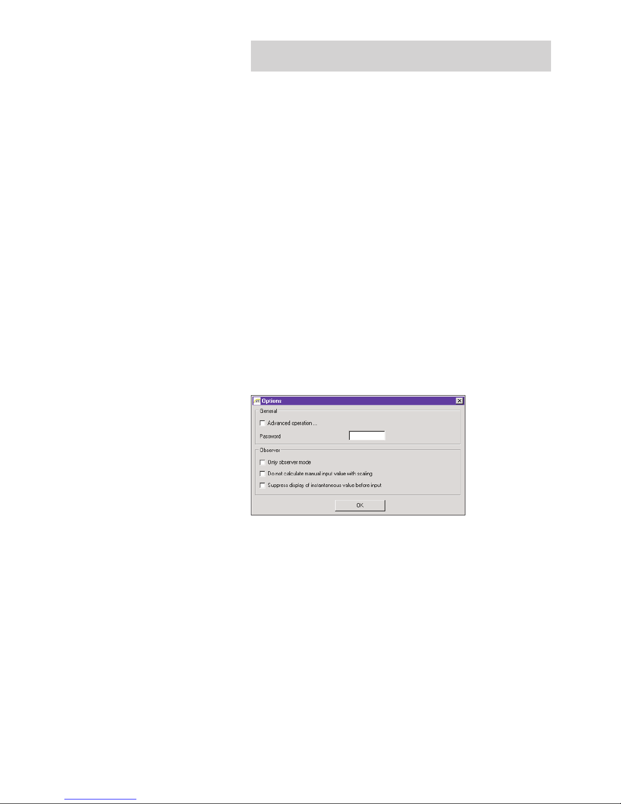
Select the "Options" function in the "File" menu. (If the option dialog cannot
be called, a password must first be entered. See Chapter 12)
Activate checkbox(es) of the required Observer option(s):
– Only observer mode
– Do not calculate manual input value with scaling
(only check value/no value change)
– Suppress display of instantaneous value before input
Click on the "OK" button.
The combination of "Only observer mode" with a password protects the operating
program against unauthorized input of operating parameters.
The "Advanced operation ..." option displays an additional button in the window
for setting the operating parameters.
Fig. 14: Input window to establish
options for the observer.
For further information on protecting the
OTT Orpheus Mini operating program with
a password, see Chapter 12.
Page 26
26
Call the Observer function as follows
Start the OTT Orpheus Mini operating program.
Set up the PC/OTT Orpheus Mini communication link (see Chapter 7.2).
Depending on the option set: In the start window of the OTT Orpheus Mini
operating program, either select "View Instantaneous values" or "Setup Device"
and in the subsequent window select the "View Instataneous values" function in
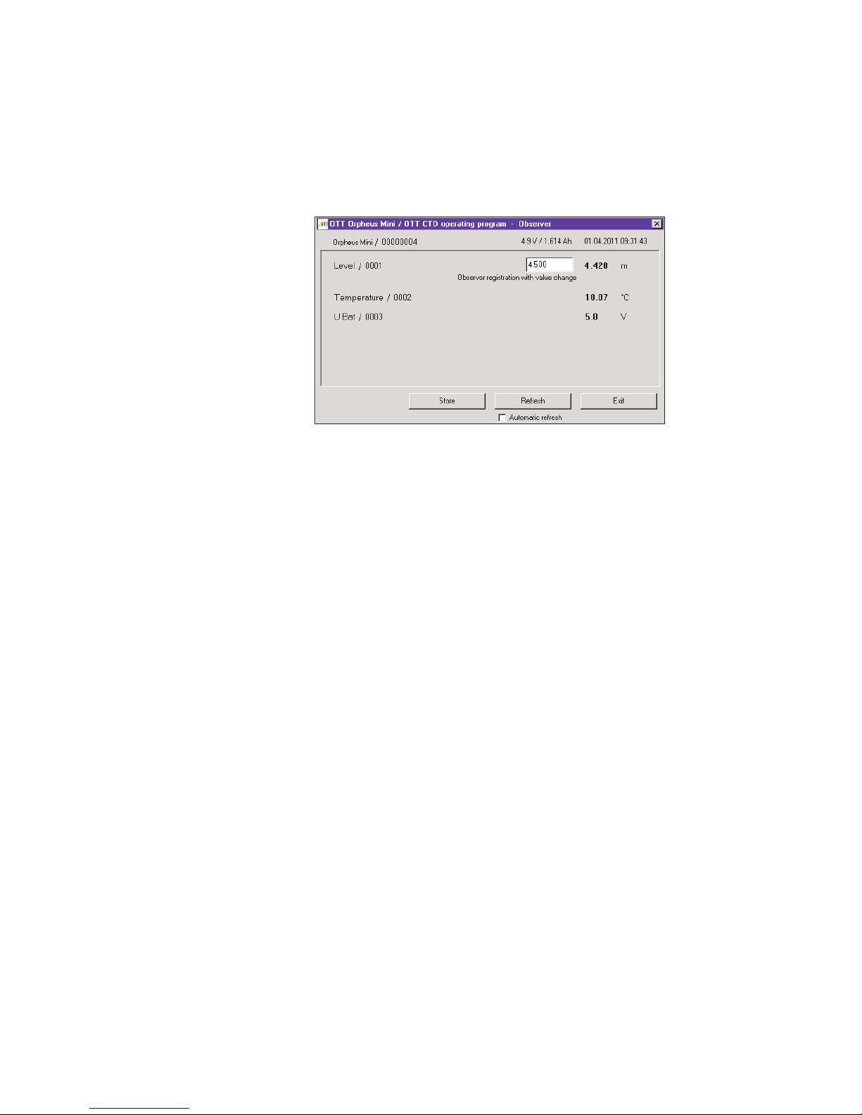
the "OTT Orpheus Mini" menu ➝ the OTT Orpheus Mini starts an instantaneous value measurement and the "Observer" window opens:
If necessary: Input Observer registration into the entry field of the pressure
sensor and click on the "Store" button.
If necessary: Start new instantaneous value measurement: click on the "Refresh"
button (" Automatic refresh" starts an instantaneous value measurement
every 5 seconds).
End the Observer: click on the "Exit" button and close the OTT Orpheus Mini
operating program.
Notes
The OTT Orpheus Mini stores each call of the Observer function in an info
channel with the date and time of day. After reading in and accepting into the
OTT Hydras 3 user software, this information can be displayed in the evaluation window of a sensor using the "Info Data" > "Station" > Show" function
("Observer registration general"). They are likewise visible via the "View/Export
data" > "Table" function of the OTT Orpheus Mini operating program.
If the " Do not calculate manual input value with scaling" check box in the
"Options" window is activated, the OTT Orpheus Mini also stores the input
check value, as well as the current instantaneous value. After reading in and
accepting into the OTT Hydras 3 user software, this information can be displayed in the evaluation window of a sensor using the "Info Data" > "Sensor" >
"Show" function ("Observer registration with check value). They are likewise
visible via the "View/Export data" > "Table" function of the OTT Orpheus Mini
oper ating program.
Fig. 15: Display/input window
"OTT Orpheus Mini operating
program – Observer".
The window displays the current instanta-
neous value for all measurements. Further-
more, the window displays the sensor
number/name, the current battery voltage,
the amount of power used from the batteries
up to now, and the date and time.
Page 27
27
9 Downloading data
Read out data as follows (on location)
Start the OTT Orpheus Mini operating program.
Set up the PC/OTT Orpheus Mini communication link (see Chapter 7.2).
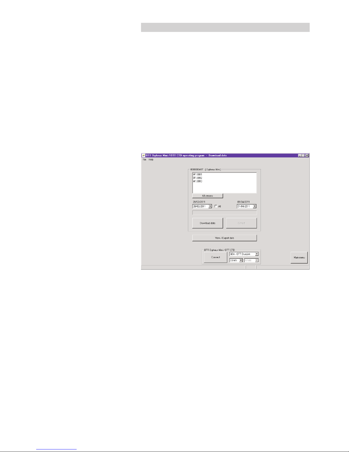
Press the "Download Data" button in the start window ➝ the operating pro-
gram displays the available sensors and the possible period for downloading
in the "Download data" window. If these values are not visible: Press the
"Connect" button.
Select the required sensors or "All sensors".
Select the required read period or "All". (The row above the entry field shows
the complete time period for which there are data.)
Click the "Download data" button ➝ the operating program copies the mea-
sured values from the OTT Orpheus Mini to the PC. The data are then available
in the program directory of the operating program.
If necessary: Display measurements via the "View/Export data" function
and/or export to a software application.
Click on the "Main menu" button.
Alternative possibilities for downloads:
With the OTT Orpheus Mini operating program and an OTT ITC
In conjunction with a modem and the OTT ITC intelligent top cap, it is also possible to establish a remote communication link with a modem. See the online help.
Using the "OTT Hydras 3 (Basic)" PC application software
Select the required station in the tree view with a double click. Make the
appropriate settings in the subsequent window and click on the "Start" button.
For further information, see the online help for the OTT Hydras 3 (Basic).
With a Pocket PC and the "OTT Hydras 3 Pocket" software.
For further information, see the OTT Hydras 3 Pocket brief instructions.
Fig. 16: Downloading data.
Page 28

28
10 Exporting data
After reading out into the OTT Orpheus Mini operating program, the measurement and information data can be found in the the "RAWDATA" sub-directory of
the program directory (standard setting: "C:\Program files\OTT\OrpheusMini_CTD\
RAWDATA"). To transfer to an external application, you can export the data in
various formats:
CSV – structured text file in CSV format (Comma-Separated Values)
Excel – Microsoft Excel spreadsheet program
OTT Hydras 3 – raw data format for the OTT Hydras 3 user software
OTT MIS – OTT-specific file format for automatically importing into the
measurement database of the OTT Hydras 3 user software
Using the "Export Options" dialog window, you can set the location for saving
and, with CSV format, various export parameters also. The data remain in the
sub-directory after export. If required, you can specifically delete them.
Info data can only be exported to the OTT Hydras 3 user software.
How to export the data
Step 1 – make export settings:
Click on the "View/Export data" button in the start window.
In the "View/Export data" window, click on the "Export Options" button
(see Figure 17).
Set the path to the location of the required export format (standard setting:
"C:\Program files\OTT\OrpheusMini_CTD\Export"). No path can be set for
the "Excel" format: the operating program automatically opens Microsoft Excel
during the export and displays the data in a new worksheet. In format "Hydras 3"
the "?" button can be used to automatically find the installation directory of
OTT Hydras 3.
In format "CSV": set the "Field separator", "Dec. separator", "Date format"
and "Time format". For the date and time formats, the typical Windows placeholders can be used.
Step 2 – Exporting data:
Select the required station/sensor in the list (multiple selection possible).
Click on the "Export ..." button.
Confirm message about successful export with "OK".
If required, delete the exported data: click on the "Delete" button.
(Station/sensor must still be selected.)
Confirm the message with "Yes".
Page 29
29
11 Displaying data
After downloading to the OTT Orpheus Mini operating program, the measurement
and information data can be found in the the "RAWDATA" sub-directory of the
program directory (standard setting: "C:\Program files\OTT\OrpheusMini_CTD\
RAWDATA"). For an initial check, you can display the data graphically and
numerically and print them out if required.
How to display data graphically
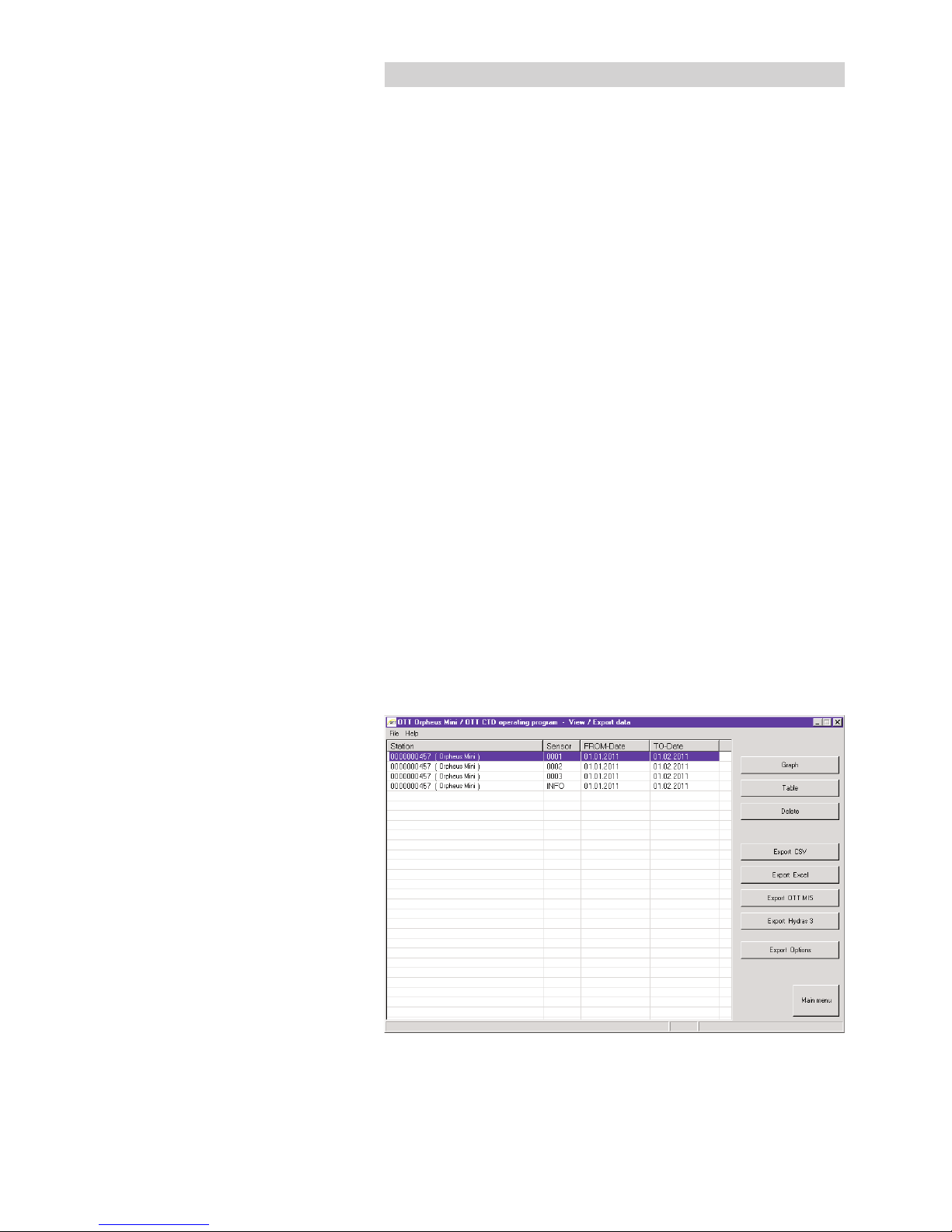
Click on the "View/Export data" button in the start window.
Select the required station/sensor in the list (multiple selection possible –
info data can only be displayed numerically).
Click on the "Graph" button ➝ the operating program displays the window
with the graphical view of the selected data;
– Show ruler: function key "F12". Move ruler: arrow keys ←→.
– Zoom in: draw the required area by dragging with the mouse.
– Zoom out: function key "F12".
Print graph: Select the "Print" function in the "File" menu.
Close graph: Select the "Exit" function in the "File" menu (or ).
How to display data numerically
Click on the "View/Export data" button in the start window.
Select the required station/sensor in the list (multiple selection possible).
Click on the "Table" button ➝ the operating program displays the window
with the numerical view of the data in the OTT data protocol;
– Only display measured values: select "Values".
– Highlight special areas (only with information data): Select "Observer &
Operation", "Alarm & Limit", "Communication & Error", "Error & Service log".
Printing the numerical display: Select the "Print" function in the "File" menu.
Closing the numerical display: Select the "Exit" button (or ).
How to delete the data
Select the required station/sensor in the list (multiple selection possible).
Click on the "Delete" button.
Confirm the message with "Yes".
Fig. 17: Viewing/exporting data.
Page 30
30
12 Protecting the OTT Orpheus Mini and OTT
Orpheus Mini operating program with a password
To prevent any unauthorized input of operating parameters, you can
protect the OTT Orpheus Mini and
OTT Orpheus Mini operating program
with a password for each.
How to protect the OTT Orpheus Mini operating program with
a password
Start the OTT Orpheus Mini operating program.
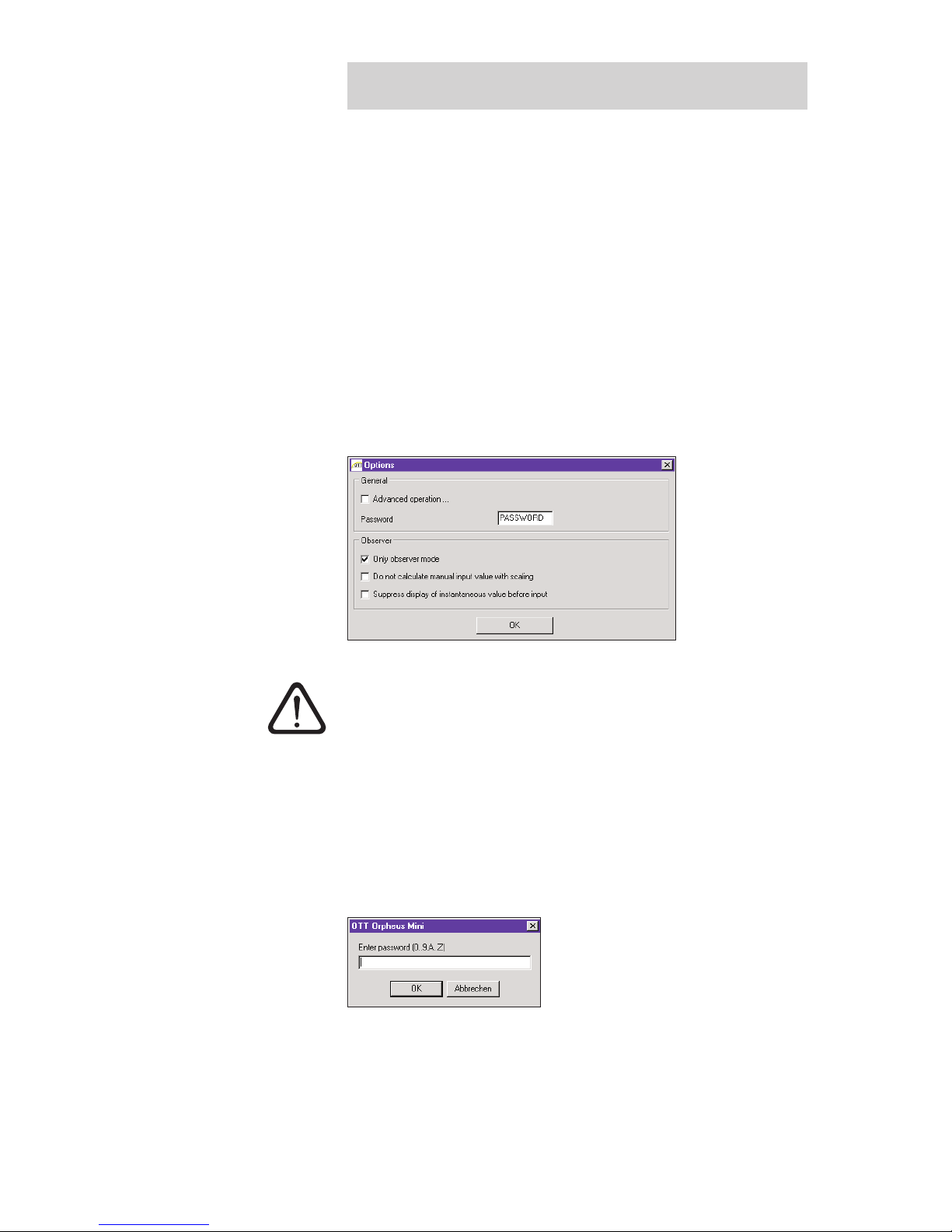
Select the "Options" function in the "File" menu.
Enter a maximum eight-digit password in the "Password" input field. Permitted
characters 0 … 9, A … Z. (This password is independent of the OTT Orpheus
Mini password.)
Activate "Only observer mode" check box.
Click on the "OK" button.
Close the operating program ➝ the operating program is now protected: the
"Setup device" button in the start window is no longer visible.
Caution:
If the password is lost, you can no longer configure or parameterize the
OTT Orpheus Mini on this PC. If this occurs, contact the OTT HydroService.
The password assigned here only relates to the OTT Orpheus Mini operating program installed on this PC. The OTT Orpheus Mini itself is not protected by this!
How to release a password-protected OTT Orpheus Mini
operating program
Start the OTT Orpheus Mini operating program.
Select the "Options" function in the "File" menu.
Enter the password in the "OTT Orpheus Mini" window.
Fig. 18: Protecting the OTT Orpheus Mini
operating program with a password –
input window to provide a password.
A password-protected operating program
only makes sense if the operating program
starts in Observer mode (activate "Only
observer mode" check box)!
Fig. 19: Releasing OTT Orpheus Mini oper-
ating program – password input window.
Page 31
31
Click on the "OK" button.
Deactivate the "Only observer mode" check box.
Remove the entry in the "Password" field.
Click on the "OK" button ➝ the operating program is released.
How to protect the OTT Orpheus Mini with a password:
Start the OTT Orpheus Mini operating program.
Set up the PC/OTT Orpheus Mini communication link (see Chapter 7.2).
Click on the "Setup Device" button in the start window.
Click on the "Advanced operation …" button.
(Button not visible? ➝ activate the "Advanced operation ..." check box in the
"Options" function in the "File" menu.)
Click on the "Connect" button.
In the tree view, select "Communication interface".
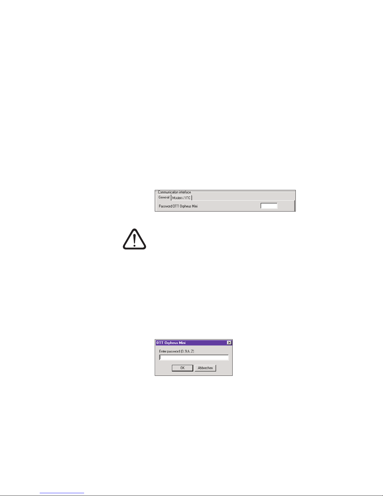
Enter a maximum eight-character password in the "Password OTT Orpheus
Mini" input field. Permitted characters 0 … 9, A … Z. (This password is independent of the OTT Orpheus Mini operating program password.)
Click on the "Connect" button.
Warning: "Reset OTT Orpheus Mini and delete data memory additionally?"
Confirm with "No" ➝ the OTT Orpheus Mini is now protected against unau thorized operation.
Caution: If the password is lost, you can no longer configure or parameterize
the OTT Orpheus Mini. If this occurs, contact the OTT HydroService.
How to release a password-protected OTT Orpheus Mini
Start the OTT Orpheus Mini operating program.
Set up the PC/OTT Orpheus Mini communication link (see Chapter 7.2).
Click on the "Setup Device" button in the start window.
Select the "Enter password" function in the "OTT Orpheus Mini" menu.
Enter password.
Click on the "OK" button.
Confirm message "Password accepted! OTT Orpheus Mini unlocked!" with "OK".
Click on the "Connect" button ➝ the operating program downloads the current
OTT Orpheus Mini operating parameters.
Fig. 20: Protecting the OTT Orpheus Mini
operating program with a password –
input window to provide a password.
Fig. 21: Releasing the OTT Orpheus
Mini – password input window.
Page 32
32
13 Date and time settings
The internal clock of the OTT Orpheus Mini is a high-accuracy, real-time clock. It
runs as soon as batteries are installed in the OTT Orpheus Mini. After the batteries
are removed, the clock will continue to run for approximately 10 more minutes.
For longer periods of power interruption, the OTT Orpheus Mini loses the date
and time. When batteries are re-installed, the OTT Orpheus Mini assumes the date
and time of the last stored measured value, with one minute added to the stored
time. The date and time are set using the OTT Orpheus Mini operating program.
Set the date and time as follows
Start the OTT Orpheus Mini operating program.
Set up the PC/OTT Orpheus Mini communication link (see Chapter 7.2).
Click on the "Setup Device" button in the start window.
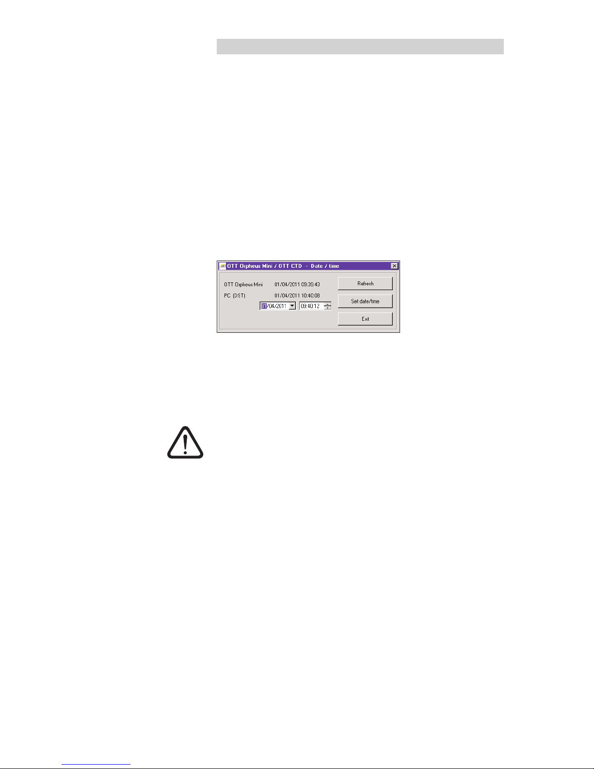
Select the "Date/time" function in the "OTT Orpheus Mini" menu (alternatively:
button "Set date/time" ➝ the oper
ating
program reads the date and time out
from the OTT Orpheus Mini and opens the "OTT Orpheus Mini – Date/time"
window.
If necessary: click on the "Refresh" button ➝ the OTT Orpheus Mini reads
out the date and time again.
If necessary: set the values required in the two input fields.
Click on the "Set date/time" button ➝ the operating program sets the
OTT Orpheus Mini date and time to the PC time/date or the values set.
Click on the "Exit" button.
Caution: If the PC is on summer time mode (ID: PC (DST)), the operating program automatically uses the standard time without summer correction (winter
time). To receive continuous time series, it is a good idea not to use summer time
in the OTT Orpheus Mini.
In connection with a GPRS remote data transfer and the "Time synchronization"
function, it is necessary to refer the time to UTC/GMT and to set the time zone of the
station in the advanced operation, "OTT Orpheus Mini" window (see online help).
Fig. 22: OTT Orpheus Mini
date and time settings.
Page 33
33
14 Deleting data memory
Caution: The stored measured values in the OTT Orpheus Mini are permanently
lost when deleting the data memory! If necessary download measured values
before deleting!
Delete the data memory as follows
Start the OTT Orpheus Mini operating program.
Set up the PC/OTT Orpheus Mini communication link (see Chapter 7.2).
Click on the "Setup Device" button in the start window.
Select the "Delete data memory" function in the "OTT Orpheus Mini" menu.
Acknowledge the warning "Are you sure you want to delete data memory?"
with "Yes" ➝ the operating program deletes the complete data memory of the
OTT Orpheus Mini (all measurement channels including the info channel). The
OTT Orpheus Mini then determines and stores the water level and the water
temperature again using the sample interval settings set.
15 Updating OTT Orpheus Mini firmware
If required, you have the possibility to update the OTT Orpheus Mini firmware
(operating system). This makes sense if, for example, devices delivered at different
times are to receive the same operating system version. Updating is carried out
via the OTT Orpheus Mini operating program. According to availability, an
updated version of the OTT Orpheus Mini firmware can be found on the internet
site "www.ott.com" in the "myOTT" area.
How to update the firmware
Download the new version of the firmware (File: e.g. "spl01m_V1.40.1.bin")
from the internet site.
Move the file "spl01m_VX.XX.X.bin" to the directory in which the
OTT Orpheus Mini operating program is located.
Set up the PC/OTT Orpheus Mini communication link (see Chapter 7.2).
Select the "Firmware update" function in the "OTT Orpheus Mini" menu.
Confirm message with "Yes" ➝ the operating program copies the new
firmware to the OTT Orpheus Mini. The OTT Orpheus Mini then determines
and stores the water level and the water temperature again using the sample
interval settings set.
Caution: During the update, avoid breaking the communication link (e.g by
accidentally removing the OTT DuoLink from the infrared interface of the
OTT Orpheus Mini.) If the communication link is broken, the firmware will no
longer run! In the same way, no other programs should be started or files
opened during the copying process!
Notes
If there are multiple ".bin" files in the directory, you will have to manually select
the required file.
The measurements saved in the OTT Orpheus Mini are not lost after an update.
Page 34
34
16 Maintenance work
16.1 Cleaning the pressure probe
Recommended interval: every 12 months
With difficult local measuring conditions (heavy
deposits): as required every 4 to 6 months.
(Measurements that are inaccurate or not plausible
indicate a contaminated pressure sensor.)
How to clean the pressure probe
Open the top cap/observation well cover.
Completely remove the OTT Orpheus Mini from the observation well.
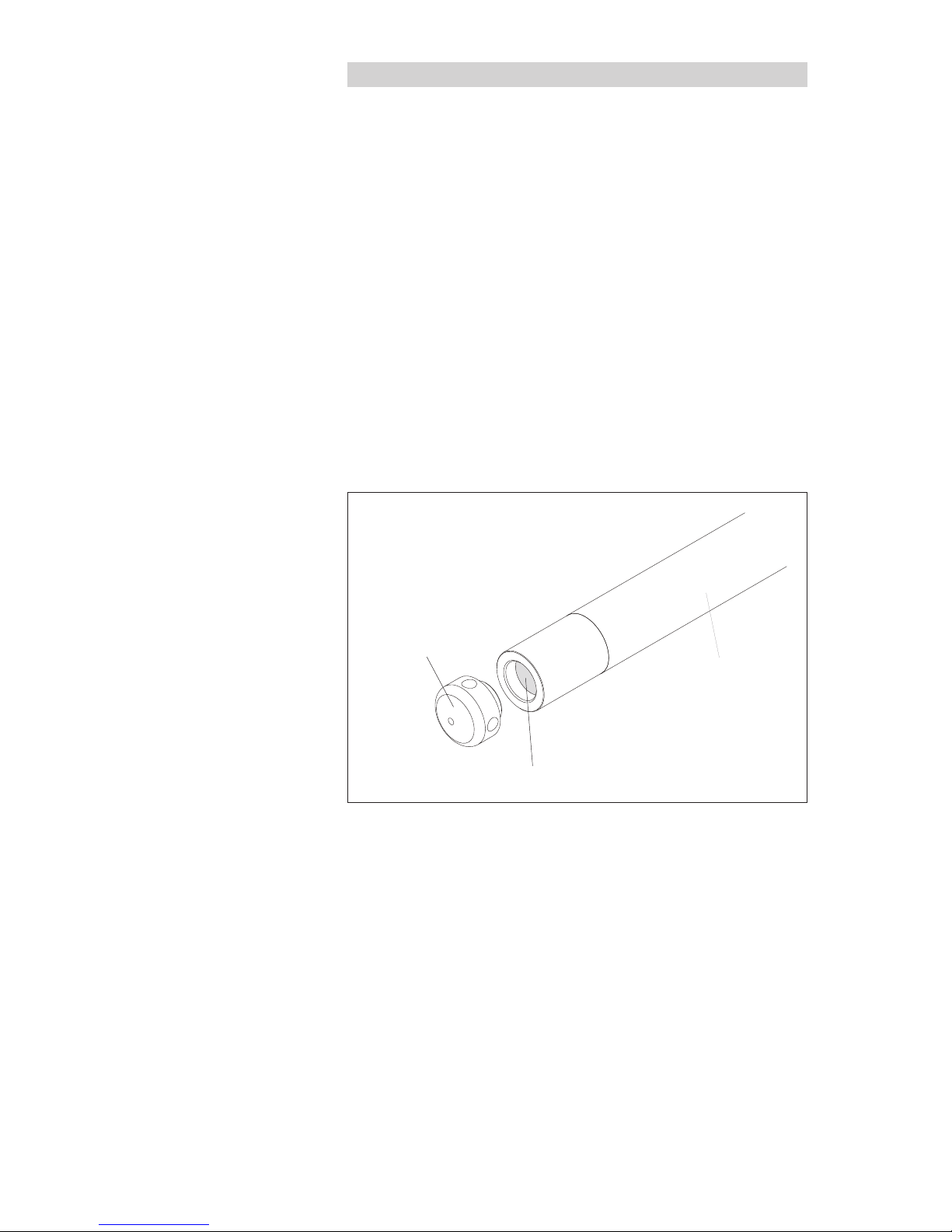
Remove the black protective cap.
Clean the pressure sensor carefully using a brush and water. Lime scale
deposits can be removed using a common household scale remover. Make
sure to follow the use and safety instructions of the scale remover!
Rinse the pressure probe thoroughly with clear water!
Reattach the black protective cap.
Reinstall OTT Orpheus Mini (see Chapter 6).
Determine current reference value with a contact gauge and enter it
(see Chapter 7.3 or 8).
Close the top cap/observation well cover.
Black
protective cap
Measuring cell
Pressure probe
with datalogger
Fig. 23: Cleaning the pressure probe.
Page 35
35
16.2 Replacing the desiccant capsules
Recommended interval: Depending on the level of air humidity at the station,
every 12 to 24 months and when replacing the batteries.
How to replace the desiccant capsules
Open the top cap/observation well cover.
Pull the communication unit approximately 80 cm out of the observation well
and hold (a second person would be useful).
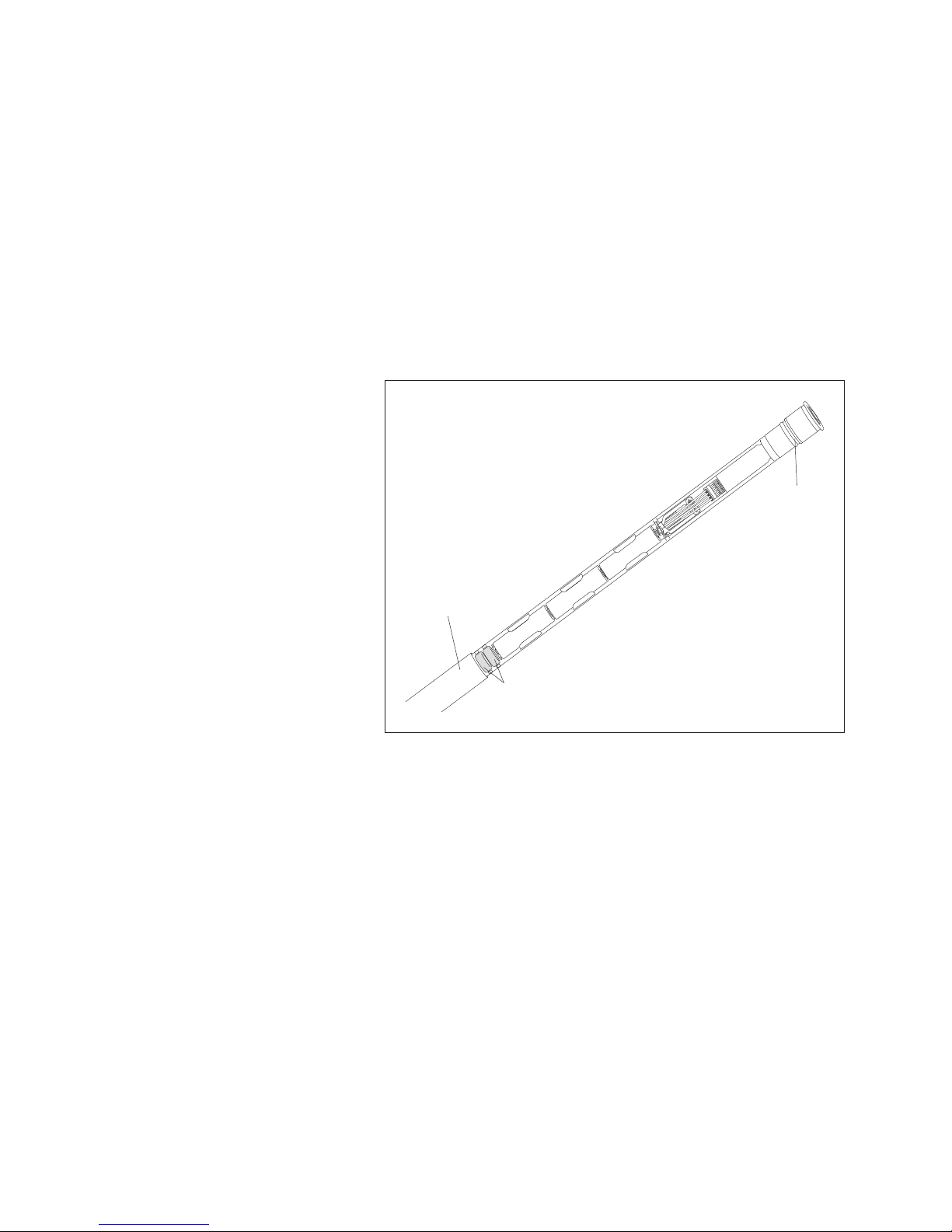
Slide the pipe casing of the communication unit approximately 30 cm in the
direction of the pressure probe cable. (The rubber stop located on the pressure
probe cable (see Fig. 1) prevents the pipe casing from falling.)
Remove used desiccant capsules.
Install 2 new desiccant capsules.
Slide the pipe casing of the communication unit back on until it stops.
Slowly and carefully replace the communication unit in the observation well.
Close the top cap/observation well cover.
16.3 Checking/replacing the batteries
See Chapter 5.
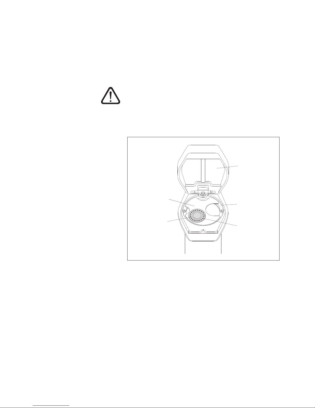
Fig. 24: Replacing the desiccant capsules
+
Communication unit
pipe housing
+
+
Desiccant capsules
Backstop
Page 36

36
17 Error messages
If erroneous measurements occur, or if an operating fault occurs, the OTT Orpheus
Mini stores one of the following error messages in the data memory instead of a
measured value.
Err 00 internal error (automated measurement)
Err 01 internal error (AD conversion error)
Err 03 Exceeded measuring range
Err 10 Measured value (still) not recorded
Internal errors indicate a device defect if they occur repeatedly.
18 Troubleshooting/fault correction
No communication possible
(operating program/OTT Orpheus Mini)
Password programmed?
➝ input correct password.
Batteries installed?
➝ install batteries.
Battery voltage lower than about 3.6 V?
➝ insert new batteries.
Battery contacts corroded?
➝ carefully clean the battery contacts.
Pressure probe cable damaged?
➝ send OTT Orpheus Mini to the factory for repair.
Infrared interface dirty?
➝ clean the infrared interface carefully with a damp, soft cloth.
Setting measured value not possible?
➝ scaling module missing. Check configuration*
(for advanced operation, see online help).
Communication starts and then breaks off
Battery voltage lower than about 3.6 V?
➝ insert new batteries.
Distance from readout unit/IrDA interface to OTT Orpheus Mini
too small/large?
➝ maintain correct distance (see Chapter7.2).
Erroneous measured values
Temperature values erroneous
➝ check configuration* (for advanced operation, see online help).
Pressure sensor values erroneous
➝ check configuration* (for advanced operation, see online help).
➝ Check the pressure compensation capillary in the communication unit
(blocked?). If necessary, clean.
➝ Check pressure sensor for contamination. Clean if necessary.
No measured values in database
Configuration incorrect?
➝ check configuration* (for advanced operation, see online help).
Battery voltage lower than about 3.6 V?
➝ insert new batteries.
* The standard factory configuration is located on the "OTT Orpheus Mini Software" CD-ROM .
Page 37
37
19 Repair
With a problem with the device, use Chapter 18, Troubleshooting/fault correc-
tion to see if you can resolve the problem yourself.
In the case of device defects, please contact the repair center ofOTT:
OTT Hydromet GmbH
Repaircenter
Ludwigstrasse 16
87437 Kempten · Germany
Telephone +49 831 5617-433
Fax +49 831 5617-439
[email protected]
Caution: Only have a defective OTT Orpheus Mini checked and repaired by
theOTT repair center. Under no circumstances carry out any repairs
yourself. Any repairs or attempted repairs carried out by the customer
will result in the loss of any guarantee rights.
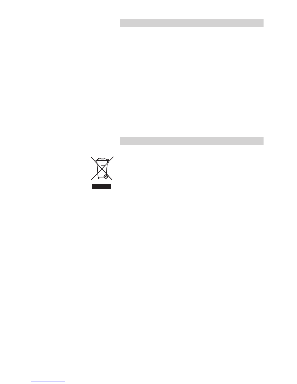
20 Notes about the disposal of old units
Within the member countries of the European Union
In accordance with the European Union guideline 2002/96/EC, OTT takes back
old devices within the member countries of the European Union and disposes of
them in an appropriate way. The devices concerned by this are marked with the
symbol shown aside.
For further information on the return procedure, please contact your local sales
contact. You will find the addresses of all sales partners in the internet on
"www.ott.com". Please take into consideration also the national implementation
of the EU guideline 2002/96/EC of your country.
For all other countries
Dispose of the OTT Orpheus Mini properly after taking out of service.
Observe the regulations applicable in your country for the disposal of
electronic devices.
Never put the OTT Orpheus Mini into the normal household waste.
Materials used
See Chapter 21, Technical data
Page 38

38
21 Technical data
Water level
Measuring range 0 … 4 m water column (0 ... 0.4 bar)
0 … 10 m water column (0 ... 1 bar)
0 … 20 m water column (0 ... 2 bar)
0 … 40 m water column (0 ... 4 bar)
0 … 100 m water column (0 ... 10 bar)
Resolution* 0.001 m; 0.1 cm; 0.01 ft; 0.1 inch
0.0001 bar; 0.001 psi
Accuracy (linearity + hysteresis) ± 0.05 % full scale
Long-term stability (linearity + hysteresis) ± 0.1 %/a full scale
0-Point ± 0.1 % full scale
Overload safe without permanent mechanical damage
0 ... 0.4 bar 4 bar
0 ... 1 bar 10 bar
0 ... 2 bar 15 bar
0 ... 4 bar 25 bar
0 ... 10 bar 40 bar
Units m, cm, ft, inch, bar, psi
Pressure sensor ceramic; temperature-compensated
Temperature-compensated operating range –5 … +45 °C (ice free)
Temperature
Measuring range –25 … +70 °C
Resolution 0.1 °C (calibrated: 0.01 °C)
Accuracy ±0.5 °C (calibrated: ±0.1 °C)
Units °C · °F
Power supply 3 x 1.5 V batteries (LR6 · AA, FR6 · AA)
alkaline or lithium design (LiFeS; Energizer L91)
Current consumption
active, measurement 30 mA
active, communication 50 mA
passive 30 µA
Service life (1 h sample interval, 50 m system length, without ITC)
with lithium batteries at least 5 years
with alkaline batteries at least 1.5 years (high quality battery types)
Clock
Design Real-time clock
Accuracy ±1 minute/month (at +25 °C)
Buffer period for battery replacement max. 10 minutes
Interface Infrared (IrDA)
Storage temperature –40 °C … +85 °C
Data memory
Measurement memory 4 MB
Number of measurements approx. 500,000
Number of logical channels 6 + 1 Info channel
Physical channels (input signals) Water level/pressure
Temperature
Supply voltage
Sample interval 1 second … 24 hours
Storage interval (mean interval) 1 second … 24 hours
* at a value range of ±32.750 m; ±3275.0 cm; ±327.50 ft; ±3275.0 inch; ±3.2750 bar; ±32.750 psi
Page 39

39
Individually configurable functions – simple or advanced operation
– 5 extended sample intervals with start/stop time indication,
support of pump tests
– Selection of units
– Pressure/level measurement or depth measurement
– With consideration of the local gravitational acceleration
– Display of instantaneous values with level monitoring function
– Password protection
– Measured value processing: Calculation of mean; delta storage;
scaling function; extreme value storage; limit control of the sample
interval
– Virtual sensor/virtual terminal
– Together with OTT ITC: alarm management;
remote data transfer
Mechanical Data
Can be installed in observation wells
– with adapter ring 1"
– with adapter plates for top caps 2", 3", 4", (4,5"), 5", 6"
with recess (OTT, HT)
– with suspension brackets for top caps ≥ 2"
without recess/universal installation
Dimensions
Communication unit L x Ø 400 mm x 22 mm
Pressure probe (L x Ø) 195 mm x 22 mm
System length (cable length including
communication unit/pressure probe) 1,5 … 200 m ±1 % ±5 cm
Weight
Communication unit (incl. batteries) approx. 0.410 kg
Pressure probe approx. 0.300 kg
Pressure probe cable approx. 0.082 kg/m
Material
Pressure probe housing POM, stainless steel 1.4539 (904 L)
Cable jacket PUR
Communication unit ABS, PC stainless steel 1.4539 (904 L)/ 1.4462 (UNS S31803)
Protection class
Communication unit IP 67 (submersion depth max. 2 m; submersion duration max. 24 h)
Pressure probe IP 68
Performance classification of the sensors
in accordance with DIN EN ISO 4373
Measurement reliability Performance class 1
Temperature range Temperature class 2
Relative humidity Class 1
EMC limits
– Resistance to electrostatic discharge (ESD) complies with EN 61000-4-2 (4 kV contact discharge)
– Resistance to electromagnetic fields complies with EN 61000-4-3 (10 V/m)
– Resistance to transient fields (burst) complies with EN 61000-4-4 (4 kV)
– Resistance to surge complies with EN 61000-4-5 (4 kV)
– Resistance to HF, asymmetric complies with EN 61000-4-6 (10 V)
– Line-borne and radiated interference complies with EN 55022 Class B (30 … 1000 MHz)
Page 40
40
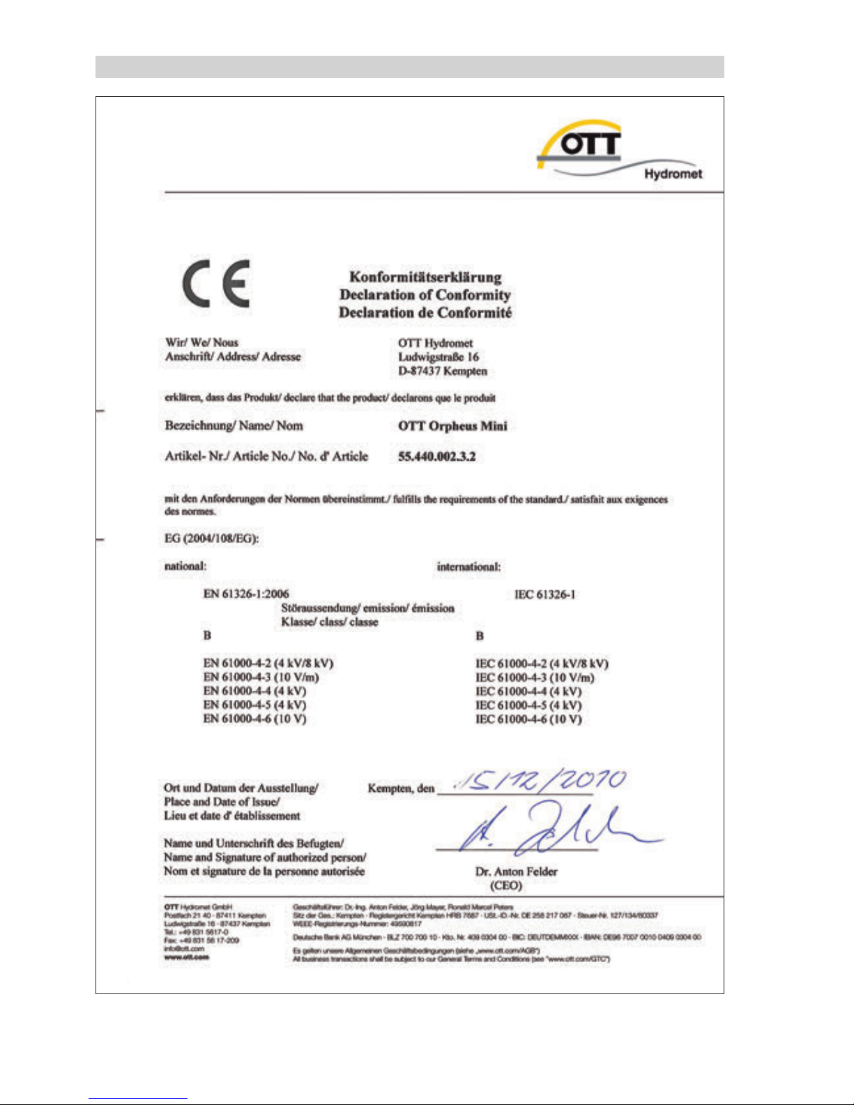
Appendix A – Declaration of conformity OTT Orpheus Mini
Page 41

Page 42

Page 43

Page 44

Document number
55.440.002.B.E 06-0311
OTT Hydromet GmbH
Ludwigstrasse 16
87437 Kempten · Germany
Tel. +49 831 5617-0
Fax +49 831 5617-209
[email protected] · www.ott.com
 Loading...