

English
Operating instructions
IP Datalogger
OTT netDL 500
OTT netDL 1000

We reserve the right to make technical changes and improvements without notice.

3
Table of contents
1 Scope of supply 5
2 Order numbers and version code 5
3 General safety information 7
4 About these operating instructions 8
5 Introduction 9
5.1 Overview of the OTT netDL IP datalogger 12
6 Overview: Starting up the OTT netDL unit 14
7 Installing the OTT netDL unit 15
7.1 Attaching the OTT netDL unit 15
7.2 Locations of the screw terminal strips and RS-232 interfaces 17
7.3 Connecting sensors having an RS-485 interface (2-wire) 18
7.4 Connecting sensors having an SDI-12 interface 18
7.5 Connecting sensors having a pulse output 19
7.6 Connecting equipment having a status output 19
7.7 Connecting sensors having a voltage output 20
7.8 Connecting sensors having a current output 20
7.9 Connecting the Pt 100 temperature sensor 21
7.10 Connecting sensors having a potentiometer (5 kOhms) 21
7.11 Connecting sensors having an RS-232 interface 22
7.12 Connecting switching contacts 22
7.13 Connecting 4-20 mA outputs 23
7.14 Connecting status outputs 23
7.15 Connecting the power supply to the OTT netDL unit 24
7.16 Connecting the GSM cellular radio antenna and inserting the SIM card 24
7.17 Connecting external communication equipment 25
7.18 Connecting an Ethernet LAN or DSL router 26
8 Setting OTT netDL operating parameters 27
8.1 Installing the OTT netDL operating program 27
8.2 Establishing the PC/OTT netDL communication link 27
8.3 If required: Installing the USB interface driver 28
8.4 Introduction: Setting OTT netDL operating parameters 29
9 Operating/configuring the OTT netDL unit on site 30
9.1 Determining and displaying instantaneous values (Observer function) 30
9.2 Entering observer texts (extended Observer function) 32
9.3 Scaling instantaneous values/stored values (set offset) 33
9.4 Displaying/setting date and time 33
9.5 Entering manual values into a manual sensor 34
9.6 Displaying information on transmissions 35
9.7 Displaying information on connections 35
9.8 Displaying system information 36
10 LED indicators 37

4
11 Reading out measured data on site 38
12 Updating the OTT netDL firmware 39
13 Overview: Alarm and action management 40
14 Protecting the OTT netDL unit using a password 41
15 Deleting the data memory 42
16 Setting date and time 42
17 Printing the connection diagram 43
18 SDI-12 transparent mode 44
19 Error messages 45
19.1 Internal error messages 45
19.2 External error messages 45
19.3 Sensor error messages 45
19.4 Processing module error messages 46
20 Maintenance 47
21 Repair 47
22 Note on the disposal of old units 48
23 Technical data 49
Appendix A: OTT netDL 1000 IP Datalogger Declaration of Conformity 52

5
1 Scope of supply
– 1 IP datalogger incl. 4 physical input channels (1 x RS-485, 1 x SDI-12,
2 x pulse/status (OTT netDL 1000: 4 x), 2 switching outputs, RS-232 interface
(OTT netDL 1000: 2 x), USB host/USB device interface, Ethernet interface
(RJ-45) (OTT netDL 1000), power supply/ground connector, 4 MB measurement
memory, LCD display, 2 status LEDs and jog shuttle; incl. two (OTT netDL 500)
or three (OTT netDL 1000) slots for expansion cards; optional GSM quadband
modem (version code "Bxx" or "Cx x")
– 1 universal power supply connector kit
– 1 OTT netDL Software CD-ROM
– 1 operating instructions
– 1 factory acceptance test (FAT) certificate
2 Ordering numbers and version code
OTT netDL 500 IP datalogger 55.553.001.9.0
incl. two slots for expansion cards
– Standard version Ax x
– Standard version + GSM modem Bx x
– Standard version + GSM modem + voice anouncer
1)
Cxx
OTT netDL 1000 IP datalogger 55.552.001.9.0
incl. three slots for expansion cards
– Standard version Ax xx
– Standard version + GSM modem Bx xx
– Standard version + GSM modem + voice anouncer
1)
Cxxx
Expansions Analog input card
2 inputs for analog input signals
– 0-20 mA/ 4-20 mA
– 0-50 mV/ 0-1.25 V/ 0-5 V/ 0-10 V
– Potentiometer, 5 kOhms
– Pt 100
Analog input card, galvanically isolated 2
Same input signals as for analog input card (see above)
RS-232 input card 3
for OTT sensors with RS-232 interface
Output card 4
Galvanically isolated output signals
– 2 outputs (4-20 mA)
– 4 status outputs (4 x 1 bit; 100 mA)
Barometric input card 5
For connecting a maximum of two pressure probes
containing Keller absolute pressure cells
1)
These device versions are expected to be available in Q2/2012
OTT netDL 500
OTT netDL 1000

Version code OTT netDL 500
Device versions: A .. B ..
C..
1)
– without expansion cards: .00
– with one expansion card: .10 .20 .30 .40 .50
– with two expansion cards: .11 .22 .33 .44 .55
.12 .23 .34 .45
.13 .24 .35
.14 .25
.15
OTT netDL 1000
Device versions: A... B...
C...
1)
– without expansion cards: .000
– with one expansion card: .100 .200 .300 .400 .500
– with two expansion cards: .110 .220 .330 .440 .550
.120 .230 .340 .450
.130 .240 .350
.140 .250
.150
– with three expansion cards: .111 .222 .333 .444 .555
.112 .223 .334 .445
.113 .224 .335 .455
.114 .225 .244
.115 .233 .245
.122 .234 .255
.123 .235
.124 .244
.125 .245
.133 .255
.134
.135
.144
.145
.155
Examples
OTT netDL 1000 standard version;
2 RS-232 input cards, 1 barometric input card
Ordering number: 55.552.001.9.0
Version code: A335
OTT netDL 500 standard version + GSM modem;
1 analog input card, 1 output card
Ordering number: 55.553.001.9.0
Version code: B14
1)
These device versions are expected to be available in Q2/2012.
Accessories Modem connection cable 97.961.069.9.5
– 1.5 meters, 9-pin Sub-D socket/
9-pin Sub-D plug
OTT netDL/PC data transfer cable 97.961.068.9.5
– 1.5 meters, 9-pin Sub-D socket/
9-pin Sub-D socket
USB connection cable 97.970.065.9.5
– USB connector type A to USB connector type B, 3 m
Flat antenna for GSM modem 97.980.060.9.5
6

3 General safety information
Read these operating instructions before using the OTT netDL for the first time!
Become completely familiar with the installation and operation of the OTT netDL
and its accessories!
Note any additional information on dangers given within the individual work
steps.
Only use the OTT netDL and its accessories in the manner described in these
operating instructions.
Make sure that the installation site is sufficiently protected against moisture
(IP 41 type of protection)!
Select the installation site so that the ambient temperature never exceeds or
falls below the allowable temperature range of –40 °C to +70 °C (for device
versions B... and C... : –30 °C to +70 °C)!
Install the OTT netDL in a closed control cabinet or in a fire protection cabinet!
If the power supply of OTT netDL is a low power source (LPS), this is not
necessary.
Do not open the OTT netDL unit! Sensors, communication equipment, power
supply, switching contacts, or additional components are connected only
through the screw terminal strips/9-pin Sub-D connectors accessible from
outside.
Operate an OTT netDL unit with built-in GSM modem (device versions B...
and C...) only with the GSM cellular radio antenna connected.
Minimum clearance between antenna and unit: 20 cm!
Before connecting the power supply, check that all wires are properly attached
to the screw terminal strips and/or 9-pin Sub D connectors.
It is essential to comply with the electrical limits given in the "Technical Data"
section.
Connect the OTT netDL only to a power supply providing less than 28 V DC.
Protect the feed line of the supply voltage with a safety fuse (10 A / fast)!
Always use a galvanically isolated safety extra-low voltage (SELV) for
mains supply.
Do not make any changes or retrofits to the OTT netDL!
Have a defective OTT netDL checked and repaired by the OTT repair center.
Under no circumstances carry out any repairs yourself.
Caution: With a nearly full data memory in the OTT netDL unit, it
may take a few minutes after an interruption of the operating
voltage until communication is possible again!
7

4 About these operating instructions
These operating instructions (revision "01-0811") cover the OTT netDL software
versions
OTT netDL firmware (operating system) from V 2.50.0
OTT netDL operating program from V 1.50.0
The version of the OTT netDL operating program can be found via the "Info"
feature in the "Help" menu.
The version of the OTT netDL firmware is found in the master data window (refer
to online help) after the OTT netDL configuration has been read into the operating
program.
In Chapter 12 "Updating the OTT netDL firmware" you will find a description on
how to update the OTT netDL firmware.
8

5 Introduction
The OTT netDL unit is a datalogger that is especially designed for hydrometry,
meterology and environmental measuring technology.
The standard version of the unit has four physical input channels, an LCD display,
and a jog shuttle. (
The jog shuttle is a special operating button that can be rotated
and pressed.)
On request, the OTT netDL is available with various expansion
cards and a built-in GSM modem. Additionally, OTT netDL 1000 has an Ethernet
interface as well as a second serial interface.
Plug-in screw terminal strips allow easy connection of sensors and power supply
without having to open the unit. Two LEDs show the operating states of the datalogger as well as of the GSM modem.
Configuration and parametrization are carried out using the "OTT netDL operating
program" PC software. This software allows the system to be conveniently and
flexibly tailored to a wide range of measurement requirements of a station.
All inputs are equipped with an internal overvoltage protection. The very low
power consumption allows the unit to be operated with solar power without
problem.
Using the internal or external GSM modem (cellular radio modem), remote data
communication as well as remote parametrization may be done over the GSM
cellular radio network (GSM = Global System for Mobile Communications). The
remote data communication can be optionally carried out via a dial-up telephone
connection, by SMS text messages, or using the packet-based GPRS mobile radio
transmission service (General Packet Radio Service). The OTT netDL 1000 unit
provides remote data communication through the Ethernet interface. Similarly,
remote data communication may be carried out via a satellite transmitter or a
cable modem.
Furthermore, the OTT netDL has individually configurable alarm and action management: If particular events occur, OTT netDL independently generates an alarm and
sends this via a modem e.g. to a control center. It is also possible to control external devices via switching contacts.
9
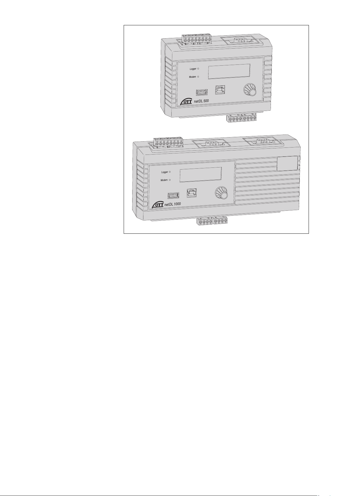
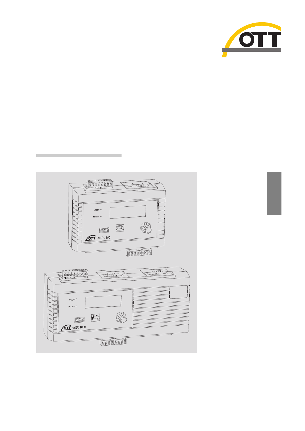
Fig. 1: OTT netDL IP datalogger
Top: OTT netDL 500
Bottom: OTT netDL 1000
10

11
Plug-in screw terminal strips
for connecting sensors
USB interfaces
LCD display
Jog shuttle
GSM antenna
connector
SIM card holder
Fig. 2: Front of the OTT netDL unit
with the status LEDs, USB interfaces
(left: Host; right: Device), and the
plug-in screw terminal strips.
The figure shows the OTT netDL 500
unit including two expansion cards
and internal GSM modem and the
OTT netDL 1000 standard version
without any expansion cards.

5.1 Overview of the OTT netDL IP datalogger
Sensor inputs
RS-485 interface (e.g. OTT RLS radar sensor, Sonicflow)
SDI-12 interface (e.g. Hydrolab DataSonde DS5, Hydrolab MiniSonde MS5)
Pulse input
Status input (2 x 1 bit)
0-50 mV, 0-1.25 V, 0-5 V, 0-10 V voltage input *
(0) 4-20 mA input (current loop) *
Pt 100 (temperature sensor) *
5 kOhm potentiometer *
RS-232 interface (OTT protocol, e.g. Nimbus bubble sensor) *
* only with analog/RS-232 expansion
Communication interfaces
RS-232 interface
USB host interface
USB device interface
Ethernet interface
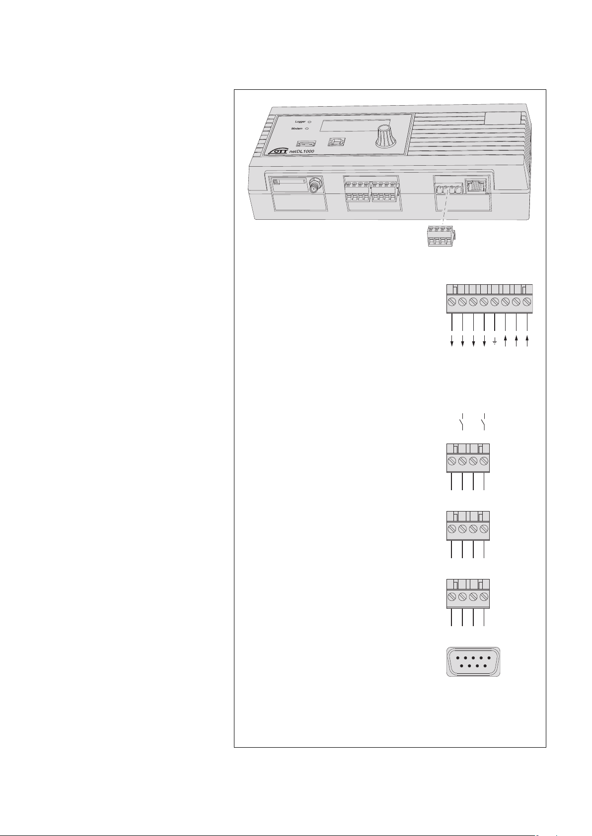
Fig. 3: Rear panels of the OTT netDL
units including the screw terminal strips
for power supply and switching contacts.
Serial interface
(RS-232/COM 2)
for extended communication
Plug-in screw terminal strip
for voltage supply
and switching contacts
Jog shuttle
Serial interface
(RS-232/COM 1)
Serial interface
(RS-232/COM 1)
Plug-in screw terminal strip
for voltage supply
and switching contacts
12

13
Communication protocols
OTT protocol
OTT HDR/ OTT HDR 1200 (satellite communication)
CREX code (satellite communication)
Terminal mode
SDI-12 transparent mode
FTP (File Transfer Protocol)
SMTP (Simple Mail Transfer Protocol)
HTTP GET/ HTTP POST (Hypertext Transfer Protocol)
Outputs
Potential-free switching output (with output card)
Voltage output for supply of sensors (switched U
bat
)
The outputs switch e.g. modem, sensor supply, or alarm devices
(potential-free switching output via relay).
Measured value processing
Sample interval
Mean calculation
Totals formation
Scaling "ax + b"
Two-point scaling
Delta storage
Definition of a sensor delay time
Extreme value collection (minimum/maximum)
Filter functions
Extreme value recording
Virtual terminal/virtual sensor (logical channels)
Linearization table
Arithmetic function
Alarm management: Limit monitoring (threshold/gradient); status alarm
Reading out/data transmission
Reading out on site via RS-232 and USB interface
Reading out via modem
Independent data transmission via modem, terminal adapter, or satellite
transmitter
ISDN D channel data transmission possible (X.31)
Independent transmission of alarm messages via SMS (e-mail/fax)
Control elements
LCD display and jog shuttle

14
6 Overview: Starting up the OTT netDL unit
Starting up a OTT netDL unit is done in a maximum of 10 steps:
Refer to chapter
1. Device versions "B..." and "C.. .":
Inserting the SIM card 7.16
2. Attaching the datalogger 7.1
3. Connecting sensors from 7.2
4. Connecting switching contacts* 7.12
5. Connecting 4-20 mA outputs* 7.13
6. Connecting status outputs* 7.14
7. Connecting the power supply 7.15
8. Device versions "B..." and "C.. .":
Connecting the GSM cellular radio antenna 7.16
9. Installing and connecting external communication equipment* 7.17
10. OTT netDL 1000: Connecting an Ethernet LAN or DSL router* 7.18
11. Configuring the datalogger and setting operating parameters 8
(also refer to the online help of the OTT netDL operating program)
* Only if required

7 Installing the OTT netDL unit
7.1 Attaching the datalogger
Requirements of the intended installation site:
Sufficient protection from moisture (IP 41 protection type).
Properly determined space for the electrical cables.
The following operating temperature ranges are kept:
Device version A.. : –40 °C up to +70 °C
Device versions B.. and C .. : –30 °C up to +70 °C
Standard top hat rail (TS 35) mounted at installation site.
Closed control cabinet or fire protection cabinet.
(not required if the power supply of OTT netDL is a low power source)
The dimensions of the OTT netDL can be found in Fig. 5.
Caution: Do not open the OTT netDL unit during installation! There are no
adjustment or operating elements or connecting means inside the housing.
Engage the OTT netDL unit into the top hat rail as shown in Figure 4 (left).
Press the underside of the OTT netDL unit against the top hat rail until it
clicks into place.
Removing the OTT netDL unit: Carefully push the unit a few millimeters upward,
slightly tilt the underside towards your body, and then remove it from the top
hat rail, refer to Figure 4 (right).
Fig. 4: Fastening the OTT netDL unit
to the top hat rail (left)/removing
it from the rail (right).
Top hat rail
15

124
18 68 232
102
all dimensions in mm
124
18 68
148
102
Fig. 5: OTT netDL unit dimensions;
Top: OTT netDL 500
Bottom: OTT netDL 1000
16
7.2 Overview of the locations of the screw terminal strips
and RS-232 interfaces
431 2
4312
4312
15
96
RS-232 interfaces
Communication COM 1 O-P O-P
COM 2 – Q-R
Serial sensor input
3)
G-H; J-K G-H; J-K; L-M
Connection of sensors
Screw terminal strip C, D + C … E +
G … K
2)
G … M
2)
4-20 mA outputs
Screw terminal strip S-T; U-V S-T; U-V; W-X
Status outputs
Screw terminal strip G-H; J-K G-H; J-K; L-M
U
Bat
0 V (GND)
U
Bat
(typ. +12 V)
U
Bat
0 V (GND)
OTT netDL … 500 1000
Voltage supply/
switching contacts
1)
Screw terminal strip N N
0 V
U
Bat
U
Bat
0 V
6 DSR
7 RTS
8 CTS
9 RI
1 DCD
2 RXD
3 TXD
4 DTR
5 GND
1)
max. 5 A
2)
G … K + G … M only with expansion cards
3)
only with RS-232 imput card
4312 8756
Switching contact
Switching contact
Switching contact
Switching contact
2
2
1
1
Fig. 6: Available positions for the
plug-in screw terminal strips.
The figure shows the OTT netDL 1000
unit without expansion cards.
Factory configuration
(without expansion cards):
OTT netDL 500: C, D + O-P
OTT netDL 1000: C-E + O-P
The specific configuration of your unit
including expansion cards as well as the
positions of the screw terminal strips/
RS-232 interfaces can be obtained from
the Factory Acceptance Test (FAT)
Certificate attached.
Please note: protect the feed line
of the voltage supply (screw terminal
strip N, contacts 6, 7 and 8) with a
safety fuse (10 A / fast)!
17

7.3 Connecting sensors having an RS-485 interface (2-wire)
7.4 Connecting sensors having an SDI-12 interface
Fig. 7: Connecting sensors with RS-485
interface and SDI-12 via RS-485 interface
(OTT protocol) to the OTT netDL unit (e.g.
OTT RLS radar sensor or OTT Parsivel Present
Weather Sensor). If multiple sensors are to
be connected to an OTT netDL unit, it is to
be done using an RS-485 bus topology.
Further information can be found in the
operating instructions of the respective sensor.
Fig. 8: Connecting sensors with SDI-12
interface to the OTT netDL unit (e.g. Hydrolab
DataSonde DS5/DS5X). If multiple sensors
are to be connected to an OTT netDL unit, it
is to be done using an SDI-12 bus topology.
Further information can be found in the
operating instructions of the respective sensor.
A sensor with SDI-12 protocol via RS-485
interface (e.g. OTT RLS radar sensor) is to
be connected as shown in Chapter 7.3!
Screw terminal strip C
RS-485 B
4312
Screw terminal strip C
SDI-12 Data
4312
18

19
7.5 Connecting sensors having a pulse output
7.6 Connecting equipment having a status output
Screw terminal strips D and E*
4312
(+)
(–)
(+)
(–)
Pulse input
* OTT netDL 1000 only
Screw terminal strips D and E*
4312
(+)
(–)
(+)
(–)
Pulse input
* OTT netDL 1000 only
Fig. 9: Connecting sensors with pulse
output to the OTT netDL unit (e.g.
OTT Pluvio precipitation sensor or
OTT Parsivel Present Weather Sensor).
The OTT netDL 500 unit has two (D 1-2,
D 3-4) and the OTT netDL 1000 unit has
four (D 1-2, D 3-4, E 1-2, E 3-4) pulse
inputs that are independent from each other.
Further information can be found in the
operating instructions of the respective sensor.
Fig. 10: Connecting devices to the
OTT netDL unit that have a status
output (e.g. door contact).
The OTT netDL 500 unit has two (D 1-2,
D 3-4) and the OTT netDL 1000 unit has
four (D 1-2, D 3-4, E 1-2, E 3-4) status
inputs that are independent from each other.

7.7 Connecting sensors having a voltage output *
7.8 Connecting sensors having a current output *
Please note: after each measurement the OTT netDL interrupts the current loop
(due to secondary effects, there is still a constant rest current of approx. 9 mA). If
other elements (e.g. display) belong to the current loop you have to close the current loop with an external resistance (R
Load
) and configurate the OTT net DL for a
sensor with voltage output.
* OTT netDL with expansion analog input card
(refer to Chapter 2 "Ordering numbers and version code")
Screw terminal strip
G-K1) / G-M
2)
U
in
+
U
in
–
4312
Screw terminal strip
G-K1) / G-M
2)
U
in
+
U
in
–
4312
0-50 mV / 0-1,25 V0-5 V / 0-10 V
1)
OTT netDL 500
2)
OTT netDL 1000
Fig. 11: Connecting sensors to the
OTT netDL unit that have a voltage
output (e.g. OTT ODS 4 K).
Further information can be found in the
operating instructions of the respective sensor.
Screw terminal strip
G-K1) / G-M
2)
I
in
+
+24 V
I
in
–
4312
Screw terminal strip
G-K1) / G-M
2)
I
in
+
I
in
–
4312
Version 2 : 0 (4)-20 mA
Current loop provided externally
Version 1 : 0 (4)-20 mA
Current loop provided internally
1)
OTT netDL 500
2)
OTT netDL 1000
Fig. 12: Connecting sensors to the
OTT netDL unit that have a current
output (e.g. OTT SE 200 shaft encoder
or OTT PLS pressure probe).
Further information can be found in the
operating instructions of the respective sensor.
Please note:
– For version 1: Do not
supply the sensor externally!
– For version 2: Additionally
supply the sensor externally!
With an OTT netDL supply voltage of higher
than 24 V (28 V max.): A sensor connected
in accordance with version 1 must be
suitable for voltages higher than 24 V!
20

7.9 Connecting the Pt 100 temperature sensor *
7.10 Connecting sensors having a potentiometer (5 kOhms) *
* OTT netDL with expansion analog input card
(refer to Chapter 2 "Ordering numbers and version code")
ϑ
Screw terminal strip G-K1) / G-M
2)
Pt 100
4312
1)
OTT netDL 500
2)
OTT netDL 1000
Fig. 13: Connecting a Pt 100 temperature
sensor to the OTT netDL unit.
Further information can be found in the
operating instructions of the respective sensor.
Screw terminal strip G-K1) / G-M
2)
5 kOhm potentiometer
4312
1)
OTT netDL 500
2)
OTT netDL 1000
Fig. 14: Connecting sensors with
potentiometer (typ. 5; max. 5.5 kOhms)
to the OTT netDL unit.
The measurement value output is
performed in values from 0 to 120 % of
the nominal value of the potentiometer.
This requires a subsequent
"2-point-scaling" of the measured value.
Further information can be found in the
operating instructions of the respective sensor.
21

7.11 Connecting sensors having an RS-232 interface *
7.12 Connecting switching contacts
* OTT netDL with expansion RS-232 input card
(refer to Chapter 2 "Ordering numbers and version code")
15
96
RS-232 interface G-H, J-K, L-M*
6 DSR
7 RTS
8 CTS
9 RI
1 DCD
2 RXD
3 TXD
4 DTR
5 GND
* OTT netDL 1000 only
Screw terminal strip N
Switching contacts 1 + 2: max. 5 A
(switched battery voltage)
0 V
U
Bat
U
Bat
0 V
4312 8756
Switching contact
Switching contact
Switching contact
2
2
1
1
U
Bat
0 V (GND)
U
Bat
(typ. +12 V)
U
Bat
0 V (GND)
Fig. 16: Connecting the OTT netDL
switching contacts.
Please note the maximum current capacity!
Fig. 15: Connecting sensors with RS-232
interface to the OTT netDL unit (e.g.
OTT Nimbus bubble sensor).
A variety of sensors with RS-232
interface require a connection using
only pins 2, 3, and 5.
Further information can be found in the
operating instructions of the respective sensor.
22

7.13 Connecting 4-20 mA outputs *
7.14 Connecting status outputs *
* OTT netDL with expansion analog output card
(refer to Chapter 2 "Ordering numbers and version code")
Fig. 17: Connecting the OTT netDL
4-20mA outputs.
Left: Connection schematic with
external supply of the current loop.
Right: Connection schematic with internal
supply of the current loop. This connecting
option requires the OTT netDL unit to be
supplied with a rated voltage of 24 V.
Be careful to dimenstion the
resistance (R
Load
) in the current
loop correctly!
Fig. 18: Connecting the
OTT netDL status outputs.
Please note the maximum current capacity!
The two outputs are galvanically isolated
from each other and from the datalogger.
Screw terminal strip
S-V
1)
/ S-X
2)
4312
Screw terminal strip
S-V
1)
/ S-X
2)
4312
+
–
4 -20 mA +
4 -20 mA –
R
Load
external supply
≤ 28 V
R
Load
* ≤ 350 Ohms
at U
Bat
= 24 V
4 -20 mA +
4 -20 mA –
–U
Bat
+U
Bat
Current loop provided
internally
Current loop provided
externally
1)
OTT netDL 500
2)
OTT netDL 1000
4312
Screw terminal strip G-K1) / G-M
2)
Status outputs
(optical coupler)
max. 0.1 A/28 V DC
1)
OTT netDL 500
2)
OTT netDL 1000
23

7.15 Connecting the power supply to the OTT netDL unit
Please note: protect the feed line of the voltage supply (screw terminal strip N,
contacts 6, 7 and 8) with a safety fuse (10 A/ fast)!
7.16 Connecting the GSM cellular radio antenna and inserting the
SIM card
(only device versions "B..." and "C.. ."): For the OTT netDL device versions
"B..." and "C. ..", a GSM cellular radio antenna (accessory) is to be
connected to the internal GSM modem and a SIM card obtained from
the cellular radio provider to be inserted into the unit.
How to connect a GSM cellular radio antenna:
Put the SMA plug of the GSM cellular radio antenna (accessory) onto the
antenna socket and slightly tighten the lock nut by hand.
Select an appropriate place for mounting the GSM cellular radio antenna
(M16 center bolt, isolating washer and 23 mm across flat width nut).
Before mounting, please note the following:
– Minimum clearance between antenna and OTT netDL unit: 0.2 m;
– Do not mount the antenna inside a metal control cabinet.
– In case of poor cellular network coverage at the installation site, consider
using a mast (including lightning protection equipment).
– If the accessory antenna is not used, the maximum antenna gain is 2.5 dBi.
–
+
–
+
–12
OUTPUTPANELAKKU
U
Bat
0 V
U
Bat
(+12 V)
Screw terminal strip N
Screw terminal strip PCU 12
4312 8756
10 A (F)
Fig. 19: Connecting voltage supply, e.g. to
an OTT PCU 12 power control unit. The OTT
PCU 12 is the OTT standard voltage supply.
Alternatively to PCU terminal 1 (load dis-
connect at a battery voltage of ≤ 7.5 V),
terminal 2 can also be used (load discon-
nect at a battery voltage of < 10.5 V).
SMA plug
GSM cellular radio antenna
Antenna socket
Fig. 20: Connecting the GSM cellular radio
antenna to the OTT netDL unit (figure shows
the OTT netDL 500 unit, proceed the same
way for the OTT netDL 1000 unit).
24

How to insert an SIM card:
Using a sharp objec (e. g. a ball pen or a pencil), press the yellow eject button.
Completely pull out the SIM card holder.
Insert the SIM card into the SIM card holder.
While doing so, please note the following:
– The gold-colored contacts of the SIM card are facing down. The beveled
edge of the SIM card is located in the front on the right-hand side!
– Do not touch the gold-colored contacts!
With the SIM card inserted, completely push the SIM card holder into the
OTT netDL unit, until it engages.
7.17 Connecting external communication equipment
If requested, a serial cable modem, a GSM modem (radio modem), or a satellite
communication unit can be connected to the OTT netDL unit.
Connect the RS-232 interface of the OTT netDL unit to a modem/satellite
communication unit using a commercially available modem connection
cable (accessory).
Optional: Connect the supply voltage of the modem using switching contacts
1 or 2 (screw terminal strip N 1-2 or N 3-4). (The modem is not permanently
powered ➝ reduces the current consumption of the station. The OTT netDL unit
enables power to the modem at specified time windows and/or when data
transfer is due.)
Fig. 21: Inserting an SIM card into
OTT netDL unit (figure shows the
OTT netDL 500 unit, proceed the same
way for the OTT netDL 1000 the unit).
Fig. 22: Modem connection cable.
(9-pin Sub-D socket to 9-pin Sub-D connector; PIN 2 and PIN 3 each directly connected;
for position(s) of the RS-232 interface(s)
on the OTT netDL unit, refer to Fig. 3; for
pin assignment of the RS-232 interface,
refer to Fig. 6).
SIM card
SIM card holder
Yellow
eject button
25

7.18 Connecting an Ethernet LAN or DSL router
Through a built-in Ethernet interface, the OTT netDL 1000 unit may be connected
to an Ethernet LAN (web access through a Local Area Network) or to a DSL router
(web access using a modem connected to a digital subscriber line (DSL)).
Connect the built-in Ethernet interface to an Ethernet LAN or DSL router using
an RJ-45 patch cable (1-to-1 pin assignment from CAT 3 on).
Fig. 23: Connecting serial modem
to the OTT netDL unit via modem
connection cable (figure shows the
OTT netDL 500 unit, proceed the same
way for the OTT netDL 1000 the unit).
Fig. 24: Connecting Ethernet LAN or
DSL router to the OTT netDL 1000.
RJ-45 patch cable
Ethernet interface
(10Base-T, 10 Mbit)
26

8 Setting OTT netDL operating parameters
To set the OTT netDL operating parameters, you need the "OTT netDL operating
program" (WBSLA0.exe) PC software. This software is found on the "OTT netDL
Software" CD-ROM (accessory).
Hardware and software requirements: Up-to-date standard PC with RS-232 interface or USB interface (desktop/tower or notebook design); operating system:
Windows2000 (SP4) or later.
8.1 Installing the OTT netDL operating program
How to install the OTT netDL operating program
Insert the CD-ROM ➝ Select "Start" | "Run" I "d:\Software\English\setup.exe"
(d = CD-ROM drive; alternatively: Select "\Deutsch" or "\Français" or
"\Español" for another language).
Follow the installation instructions on the screen.
8.2 Establishing the PC/OTT netDL communication link (on site)
In the Chapters 8 and 11 to 18, the establishment of a communication link
between the OTT netDL and a PC is a pre-requisite for the following steps.
The following description illustrates the setup of this communication link and
its variations.
Hardware and software requirements: Up-to-date standard PC with RS-232 interface or USB interface (desktop/tower or notebook design); operating system:
Windows2000 (SP4) or later.
Additional (accessories):
OTT netDL/PC data transfer cable (see accessories; null modem cable)
USB connection cable
RJ-45 crossover cable for direct connection between PC and OTT netDL
RJ-45 patch cable for connection via switch or router
How to set up a communication link using a data transfer cable
Connect the data transfer cable (9-pin Sub-D socket to 9-pin Sub-D socket;
pins 2 and 3 each crossed) to a serial interface of the PC (e.g. COM 1).
Connect the data transfer cable to the serial communication interface of the
OTT netDL (COM 1 or COM 2 (OTT netDL 1000 only)).
Start the OTT netDL operating program.
In the OTT netDL operating program, select the serial interface (COM1, COM2)
and transmission speed used in the "RS232/V.24" communication path.
How to set up a communication link using a USB connection cable
Requirements: USB interface drivers are installed (refer to Chapter 8.3).
Connect the USB connection cable to a USB socket of the PC
(USB connector type A).
Connect the USB connection cable to the USB device interface of the OTT netDL
(USB connector type B).
Start the OTT netDL operating program.
In the OTT netDL operating program, select the "USB Connection" com -
munication path.
27

How to set up a communication link using an RJ-45 crossover cable
The OTT netDL must be configurated accordingly (IP-address, …); see online help
of the operating program.
Connect the RJ-45 crossover cable to an Ethernet interface of the PC.
Connect the RJ-45 crossover cable to the Ethernet interface of the OTT netDL unit.
Start the OTT netDL operating program.
In the OTT netDL operating program, select the "IP Connection" communication
path.
Notes
Change the language for the OTT netDL operating program as required:
Press the F3 function key (multiple times) until the required language appears.
For more information on setting up a communication link (also from remote),
please refer to the online help of the OTT netDL operating program.
Caution: With a nearly full data memory in the OTT netDL unit, it
may take a few minutes after an interruption of the operating
voltage until communication is possible again!
8.3 If required: Installing the USB interface driver
For establishing a communication link over the USB interface, the PC requires a
dedicated USB interface driver. This USB interface driver must be installed, when
the communication link is established for the first time.
You may use the USB interface driver on any current standard PC that is fitted with
a USB interface and on which a Microsoft Windows 2000 or higher operating
system is run.
The procedure described here is based on the Microsoft Windows XP operating
system. With minor changes, it applies to the other Windows operating system
versions as well.
How to install the USB interface driver:
Log on to the PC with administrator rights.
Connect the OTT netDL unit to a USB interface of the PC ➝ the PC detects
the new hardware and displays the message*: "Found New Hardware –
OTT netDL" ➝ the "Found New Hardware Wizard" opens.
Select "No, not this time".
Select "Next".
Select "Install from a list or specific location (Advanced)".
Select "Next".
Insert the "OTT netDL Software" CD-ROM into the PC drive.
Select "Search for the best driver in these locations" and "Search removable
media (floppy, CD-ROM ...)".
Select "Next".
The wizard will install the USB interface driver onto the PC.
After completion of the installation process, the following message will appear:
"The wizard has finished installing the software for: OTT netDL".
Select "Next". Now a communication link via the USB interface may be
established.
* In the notification area of the taskbar
Note
The USB driver depends on the particular OTT netDL unit. Therefore, the driver
must be installed for each new OTT netDL unit once.
28

29
8.4 Introduction: Setting OTT netDL operating parameters
How to set the OTT netDL operating parameters using a PC:
Establish the PC/OTT netDL communication link (refer to Chapter 8.2).
If you have not already done so: Connect the OTT netDL unit to operating
voltage. After a few seconds, the OTT netDL unit is ready to use (the LCD
display shows various messages and then turns off).
Start the OTT netDL operating program.
In the "Device" menu, select the "netDL 500/1000" option.
Read the current OTT netDL configuration into the operating program: In the
"netDL 500/1000" menu, select the "Read" option or click the "Read" button
➝ The operating program reads the current (factory default) OTT netDL con figuration and displays it in the operating program main window:
Now make the adjustments according to your specific requirements:
– Master data
– Interfaces
– Devices
– Connections IP
– Server
– Transmissions
– Maintenance window
– Time synchronization
– Action management
– Display/Observer
– Channel-related function
Click on the "Program" button.
Acknowledge the message "Warning: Reset OTT netDL and delete data memory
additionally?" by selecting "Yes" (recommended for initial installations).
The OTT netDL is now completely configured and parametrized and starts
processing the measuring and communicating jobs.
For detailed information on how to set the OTT netDL operating parameters,
please refer to the online help of the OTT netDL operating program.
Fig. 25: Main window of the
OTT netDL operating program.

9 Operating/configuring the OTT netDL unit on site
For operating the unit on site, OTT netDL is equipped with a backlighted LCD display
(4 rows x 20characters) and a "jog shuttle". The jog shuttle is a special operating
button that can be rotated and pressed.
The following functions can be called with the jog shuttle:
Determine and display instantaneous values (Observer function)
– with input of a check value,
– without input of a check value.
Enter observer texts
(extended Observer function)
Scale instantaneous values/stored values
(set offset)
Display/set date and time
Display information on transmissions
Display information on connections
Display system information
Start voice announcer (optional)
Meaning of the function symbols on the LCD display
! "Enter observer text"
¥ "continue"
√ "enter"
≈ "cancel" / "exit" / "back"
9.1 Detecting and displaying instantaneous values
(Observer function)
Requirements
The configuration of a channel that is to determine and display an instanta-
neous value must include the "Instantaneous value" function block (refer to
online help).
If additional check values are to be entered, the "Observer Manual input"
option in the "Display/Observer" function block must be activated (refer to
online help).
How to determine and display instantaneous values without
entering a check value:
Press jog shuttle twice. (Between the first and second presses, the
LCD display
shows the OTT netDL firmware version.)
The OTT netDL unit activates the
LCD
display
and shows the selection menu (if password protection for the LCD
display is active ➝ enter the four-digit password first; refer to online help).
Press jog shuttle (Observer). The
LCD display
shows the station name, the
station number, the current time and, after 2 seconds, the level of the voltage
supply.
Press jog shuttle (¥). The
LCD display
shows the screw terminal strip used, the
sensor name/number and the instantaneous value of the first channel (sensor).
To show the instantaneous values of additional channels, press jog shuttle once
each time (¥). After the instantaneous value of the last channel has been
shown, the LCD display shows the instantaneous value of the first channel
again.
To end the display of the instantaneous values, rotate jog shuttle to ≈ and press
(twice). If the jog shuttle is not used for three minutes, the LCD display shuts off
automatically.
30

31
How to determine and display instantaneous values when entering a check value:
Press jog shuttle twice. (Between the first and second presses, the
LCD display
shows the OTT netDL firmware version.)
The OTT netDL unit activates the
LCD
display
and shows the selection menu (if password protection for the LCD
display is active ➝ enter the four-digit password first; refer to online help).
Press jog shuttle (Observer). The
LCD display
shows the station name, the
station number, the current time and, after 2 seconds, the level of the voltage
supply.
Press jog shuttle (¥). The
LCD display
shows the screw terminal strip used and
the sensor name/number of the first channel (sensor). If the "Suppress display
of instantaneous value before input" option in the "Display/Observer" function
block is activated, the OTT netDL unit suppresses the instantaneous value by
means of asterisks.
Rotate jog shuttle to √.
Press jog shuttle (√). The check value is now to be entered by character from
right to left. The character to be changed in each case is shown inverted (white
on black background).
Rotate jog shuttle until required character appears.
Press jog shuttle to jump to the next character position, etc.
Confirm the entry: Press jog shuttle (√). Cancel: Rotate jog shuttle to
≈ and press.
Press jog shuttle (¥). The OTT netDL unit now determines the current instan -
taneous value of the first channel (sensor) and shows it on the
LCD display
.
To enter the check value and show the instantaneous values of additional channels,
press jog shuttle once each time (¥). After the instantaneous value of the last
channel has been shown, the LCD display shows the instantaneous value of the
first channel again (it is not necessary to enter a check value again).
To end the display of the instantaneous values, rotate jog shuttle to ≈ and press
(twice). If the jog shuttle is not used for three minutes, the LCD display shuts off
automatically.
Notes
The "Observer" function initiates an instantaneous value measurement. Until
this measurement is complete, the display refers to the last stored value (or the
instantaneous value last displayed, whichever is the most recent). On the display, this is identified with an "s" after the channel number (sensor number).
After completing the measurement, the new measured value appears without
additional identification.
The OTT netDL stores each call of the "Observer" function in the info channel
together with date and time. After "Read" and "Accept", this information can
be displayed in the evaluation window of a sensor in the Hydras 3 application
software using the "Info Data | Station | Display" option (observer registration
general).
If the "Observer Manual input" option in the "Display/Observer" function block
is activated, the OTT netDL also stores the check value entered as well as the
currently measured instantaneous value. These two values can be displayed in
the evaluation window of a sensor after being "Read" and "Accept" to the
Hydras 3 application software using the "Info Data | Sensor | Display" function (observer registration with check value).

9.2 Entering observer texts
(extended Observer function)
Requirements
The "Extended observer (store and transmit number)" option in the
"Display/Observer" function block is activated (refer to online help).
In the "Display/Observer" function block, observer texts are stored
(refer to online help).
How to enter observer texts for the station:
Press jog shuttle twice. (Between the first and second presses, the LCD display
momentarily shows the OTT netDL firmware version.)
The OTT netDL activates the
LCD display
and
shows the selection menu.
Press jog shuttle (Observer). The
LCD display
shows the station name, the
station number, the current time and, after 2 seconds, the level of the voltage
supply.
Rotate jog shuttle to !.
Press jog shuttle in order to begin the entry of the observer texts.
Rotate jog shuttle until the required number/text appears and then press. (The
numbers are not necessarily sorted in ascending order. The row numbers of the
table entries of the observer texts are decisive; refer to online help). By selecting
the number 0000, freely editable texts can be entered.
Confirm the entry: Press jog shuttle (√). Cancel: Rotate jog shuttle to ≈ and
press.
To end the entry of the observer text, rotate jog shuttle to ≈ and press. If the
jog shuttle is not used for three minutes, the LCD display shuts off automatically.
How to enter observer texts for a channel (sensor):
Press jog shuttle twice. (Between the first and second presses, the
LCD display
momentarily shows the OTT netDL firmware version.)
The OTT netDL unit activates
the
LCD display
and shows the selection menu (if password protection for the
LCD display is active ➝ enter the four-digit password first; refer to online help).
Press jog shuttle (Observer). The
LCD display
shows the station name, the
station number, the time and, after 2 seconds, the level of the voltage supply.
Rotate jog shuttle to !.
Press jog shuttle (¥). The
LCD display
shows the instantaneous value of the first
channel (sensor).
Note
The application software Hydras 3, version 2.00.0, only displays the observer
texts in numerical form within the raw data management.
How to enter freely editable text:
Select number 0000 (see above).
Press jog shuttle (√) to begin with text entry.
Rotate jog shuttle until required alphanumeric character appears.
Press jog shuttle to jump to the next character position, etc.
Confirm the entry: Press jog shuttle (√).
32

9.3 Scaling instantaneous values/stored values (set offset)
How to change (scale) an instantaneous value:
To change a value: Rotate jog shuttle clockwise until "√" is selected (text with
black background).
Press jog shuttle (√). The value is now entered by character from right to left.
The character to be changed in each case is shown inverted (white on black
background).
Rotate jog shuttle until required character appears.
Press jog shuttle to jump to the next character position, etc.
Please note: Changing an instantaneous value in the display is only avail-
able for channels for which the "Scaling y=ax + b" or "2-point scaling"
function block has been created during the configuration (refer to online help).
Changing an instantaneous value will affect the scale of this channel (offset).
The OTT netDL records instantaneous value changes in the "Info channel" of a
sensor (evaluation with Hydras 3).
Confirm the entry: Press jog shuttle (√). Cancel: Rotate jog shuttle to ≈ and
press.
To change an additional instantaneous value: Rotate jog shuttle (¥) and press.
9.4 Displaying/setting date and time
How to set the date and time:
Press jog shuttle twice. (Between the first and second presses, the LCD display
momentarily shows the OTT netDL firmware version.) The OTT netDL unit activates
the LCD display and shows the selection menu (if password protection for the
LCD display is active
➝
enter the four-digit password first; refer to
online help
).
Rotate jog shuttle (SettinÌs).
Press
jog shuttle
(Date/Time).
Press
jog shuttle
.
Press jog shuttle. The OTT netDL unit shows the current time and date.
How to set the date and time:
Press jog shuttle (√).
Change number (↕): Rotate jog shuttle.
Jump one number to the right (➝): Press jog shuttle. After moving to the
seconds, the OTT netDL shows "√" and "≈".
Set date/time (store): Press jog shuttle (√).
Alternatively, the date and time can be set via the "OTT netDL operating
program": "OTT netDL menu, „Date / time" function.
33

34
9.5 Entering manual values into a manual sensor
Requirements
The configuration of a channel that is to allow the entry of manual values must
include the "Manual Sensor" function block (refer to online help).
How to enter manual values:
Press jog shuttle twice. (Between the first and second presses, the
LCD display
momentarily shows the OTT netDL firmware version.)
The OTT netDL unit activates
the
LCD display
and shows the selection menu (if password protection for the
LCD display is active ➝ enter the four-digit password first; refer to online help).
Press jog shuttle (Observer). The
LCD display
shows the station name, the
station number, the current time and, after 2 seconds, the level of the voltage
supply.
Rotate jog shuttle to ! and press.
The LCD display shows a selection menu. This menu is only visible if the
Observer feature is activated ("Display/Observer" function block, "General"
tab, "Observer Manual input").
Rotate jog shuttle to Manual Sensor and press.
The LCD display shows the first sensor for manual input. For manual input of
additional channels, press jog shuttle (¥) or rotate to √.
To start manual input, press jog shuttle (√).
The manual value is now entered by character from right to left. The character
to be changed in each case is shown inverted (white on black background).
Rotate jog shuttle until required character appears.
Press jog shuttle to jump to the next character position, etc.
After entering the manual value, the time applicable to it is entered from right
to left. The character to be changed in each case is shown inverted (white on
black background): The OTT netDL shows the current time as the default.
Rotate jog shuttle until required character appears.
Press jog shuttle to jump to the next character position, etc.
Confirm the entry: Press jog shuttle (√). Cancel: Rotate jog shuttle to ≈ and
press.
To show the manual input of additional channels, press jog shuttle once each
time (¥). After the manual input of the last channel has been shown, the LCD
display shows the manual value entry made for the first channel again.
To end the display of the manual input, rotate jog shuttle to ≈ and press
(twice). If the jog shuttle is not used for three minutes, the LCD display shuts
off automatically.
Note
The OTT netDL unit saves a manual sensor in the same way as a normal
aperiodic sensor, together with measured value, date and time.

35
9.6 Displaying information on transmissions
A transmission is a remote data transfer that is configured in the OTT netDL
operating program and which the OTT netDL unit independently executes over
a specified communication path.
How to display information on transmissions:
Press jog shuttle twice. (Between the first and second presses, the
LCD display
momentarily shows the OTT netDL firmware version.)
The OTT netDL unit activates
the
LCD display
and shows the selection menu (if password protection for the
LCD display is active ➝ enter the four-digit password first; refer to online help).
Rotate jog shuttle to Information and press.
Press jog shuttle (Transmissions).
The LCD display shows information on the first transmission:
Line 1: Name of the transmission;
Line 2: Unit through which the data transmission takes place:
Line 3: Date and time of the last transmission through this communication path.
Show other transmissions: Rotate jog shuttle to ¥ and press.
Exit display: Rotate jog shuttle to ≈ and press.
Then rotate Jog shuttle twice to End and press.
9.7 Displaying information on connections
A connection is a communication path that is specified in the OTT netDL operating
program and used for remote data transfer (GPRS data transfer over cellular radio
modem or Ethernet or internet connection).
How to display information on connections:
Press jog shuttle twice. (Between the first and second presses, the
LCD display
momentarily shows the OTT netDL firmware version.)
The OTT netDL unit activates
the
LCD display
and shows the selection menu (if password protection for the
LCD display is active ➝ enter the four-digit password first; refer to online help).
Rotate jog shuttle to Information and press.
Rotate jog shuttle to Connections and press.
Optionally press
– jog shuttle (Modem) or
– rotate jog shuttle (LAN) and press.
Press jog shuttle (Saved state).
The LCD display shows information on the connection:
Line 1: Menu item Modem ➝ Network operator: Signal strength;
Menu item LAN ➝ Transmission speed of the Ethernet interface;
Line 2: IP address;
Line 3: Date and time of the last status logging.
Show current status: Rotate jog shuttle to ≈ and press.
Rotate jog shuttle to Saved state and press ➝ the OTT netDL unit deter-
mines the current connection status and displays the information (see above).
Press jog shuttle (End).
Show other connections: Rotate jog shuttle to ¥ and press.
Exit display: Rotate jog shuttle to ≈ and press.
Then rotate Jog shuttle twice to End and press.
Note
If the OTT netDL is unable to establish a connection, the LCD display shows
"- - - - - - -" and "---.---.---.---".

36
9.8 Displaying system information
Upon request, the OTT netDL shows the last 10 events recorded (event log) as well
as the particular device version (Systeminfo).
How to display the event log:
Press jog shuttle twice. (Between the first and second presses, the
LCD display
momentarily shows the OTT netDL firmware version.)
The OTT netDL unit activates
the
LCD display
and shows the selection menu (if password protection for the
LCD display is active ➝ enter the four-digit password first; refer to online help).
Rotate jog shuttle to Information and press.
Rotate jog shuttle to System and press.
Press jog shuttle (Event LoÌ).
The LCD display shows information on the first event:
Line 1: Function, instance
Line 2: Type, code
Line 3: Date and time of the event
Show information on the event in clear text ➝ Rotate and jog shuttle to select
the line 1 or 2, and press.
Exit clear text display: Press jog shuttle (End).
Display information on next event: Rotate jog shuttle to ¥ and press.
Show other events: Rotate jog shuttle to ¥ and press.
Exit display: Rotate jog shuttle to ≈ and press.
Then rotate Jog shuttle three times to End and press.
How to display the device version:
Press jog shuttle twice. (Between the first and second presses, the
LCD display
momentarily shows the OTT netDL firmware version.)
The OTT netDL unit activates
the
LCD display
and shows the selection menu (if password protection for the
LCD display is active ➝ enter the four-digit password first; refer to online help).
Rotate jog shuttle to Information and press.
Rotate jog shuttle to System and press.
Rotate jog shuttle to Systeminfo and press.
The LCD display shows information on the system:
Line 1: Type and position of the expansion card/display/mainboard/modem
Line 2: Hardware revision
Line 3: Software revision.
Display other system information: Rotate jog shuttle to ¥ and press.
Exit display: Rotate jog shuttle to ≈ and press.
Then rotate Jog shuttle three times to End and press.

10 LED indicators
For indicating different operating states, the OTT netDL unit front panel has two
multi-color LEDs:
"Logger" LED – Flashes green; frequency: once every 2 seconds
➝ datalogger active.
– Flashes green; frequency: once per second
➝ IP data communication active.
– Flashes red; frequency: once per second
➝ IP data communication failed.
– Off
➝ datalogger in sleep mode.
"Modem" LED – Continuously illuminates green
➝ internal modem active.
– Continuously illuminates orange
➝ GPRS data communication available.
– Off
➝ internal modem inactive.
37

11 Reading out measured data on site
To retrieve measured data from an OTT netDL unit, a PC with the "Hydras 3
Application Software (Basic)" is required.
How to retrieve measured data on site:
Connect the RS-232C interface of the OTT netDL to a serial interface of your PC
(also refer to Chapter 8.2).
Start Hydras 3 (Basic).
In the tree view of HYDRAS 3, select the station; in the "Communication" menu,
select the "Read / Operate" option.
In "Communication" window, type "OTT netDL, "Read", do the following: select
"Standard". The protocol type is preset to "OTT protocol (Hydrosens)". For the
communication path, select "RS232C/V.24, COM1 (or COM2), 115200Bd,
8N1". Click on "Start".
The measured values are copied from the PC and are available in the raw data
pool for further use.
Moreover, you may retrieve the measured data through remote data transfer using
a modem. For detailed information, refer to the online help of the OTT netDL operating program.
Fig. 26: Reading out measured data on site.
38

12 Updating the OTT netDL firmware
The "OTT netDL, operating program" provides the option of updating the
OTT netDL firmware (operating system). By continuously developing the operating
system, you will thus be provided with the extended functionality for the
OTT netDL, even with the same hardware.
By accessing the OTT website (www.ott.com; "myOTT" section) from time to time,
stay informed on the current version of the OTT netDL firmware.
How to update the firmware:
Download the new version of the firmware (file: e.g. "SLI_netDL_V2.50.1.bin")
from the website.
Copy the file "SLI_netDL_Vx.xx.x.bin" to the directory, in which the OTT netDL
operating program is located.
Establish the PC/OTT netDL communication link (refer to Chapter 8.2).
In the "OTT netDL ..." menu, select the "New program code" option.
Acknowledge the confirmation by selecting "Yes" ➝ The operating program
copies the new firmware to the OTT netDL unit (LCD display: "Update in
progress"). Then the OTT netDL will restart and automatically resume processing its measuring and communicating jobs.
Caution: During update, make sure that the communication link is not aborted
(e.g. by accidentally answering calls on the data transfer cable). If the communication link is aborted, the firmware will no longer be executable! In the same
way, no other programs should be started or files opened during the copying
process!
Note
If there are multiple ".bin" files in the directory, you will have to select the
required file manually.
The measured values saved in the OTT netDL are not lost after an update.
39

13 Overview: Alarm and action management
The OTT netDL is capable of automatically generating an alarm or performing
an action, if certain events occur. These alarms or actions may be triggered by
different conditions:
Threshold of a limit: A predefined value is underrun or exceeded.
Gradient limit: Fast rise or drop of a defined value within a certain period
of time.
Change in status: The input signal at a status input has changed.
The following actions and alarm messages are available:
Control external devices through the power supply switching contact
(switched U
bat
).
Send an SMS message containing an alarm message. If the cellular radio
network operators provide respective services, the SMS messages may be
sent as an e-mail or telefax as well.
Send an alarm message via OTT protocol to the OTT Hydras 3 application
software.
Send an alarm message to an HTTP/FTP/SMTP server.
Temporarily change the transmitting interval of a configured data transfer.
For this, there are five additional time intervals available that are controlled
by limits.
(Temporarily) change the sampling and storage interval of a channel.
If required, individual actions may be grouped. Thus, an event may trigger several
actions/alarms.
For detailed information on the alarm and action management, refer to the online
help of the OTT netDL operating program.
40

41
14 Protecting the OTT netDL unit using a password
To protect an OTT netDL against unauthorized configuration or entry of operating
parameters, you may lock the OTT netDL unit using a password.
This only applies to the interaction with the OTT netDL operating program.
How to protect the OTT netDL against unauthorized operation:
Establish the PC/OTT netDL communication link (refer to Chapter 8.2).
Read the current OTT netDL configuration into the operating program: In the
"netDL 500/1000" menu, select the "Read" option or click on the "Read" button.
In the tree view, select "netDL 500/1000".
Enter an eight-digit (max.) password into the "Password" input box.
Allowable characters: 0-9, A-Z.
Click on the "Program" button.
Acknowledge the message "Warning: Reset the netDL and delete data memory
additionally?" by selecting "No" ➝ The OTT netDL unit is now protected
against unauthorized operation.
Caution: Keep the password in a safe place. If the password is lost, you can no
longer configure or parametrize the OTT netDL unit. In such a case, please contact
OTT HydroService.
How to unlock the OTT netDL for operating:
In the "netDL 500/1000" menu, select the "Enter password" option.
Enter password.
Click on the "OK" button.
Acknowledge the " Password accepted! OTT netDL unlocked" message
by selecting "OK".
Click the "Read" button ➝ The operating program reads the current
OTT netDL configuration.

15 Setting date and time
The internal clock of the OTT netDL is a highly accurate realtime clock. If the supply voltage is interrupted, the installed lithium battery provides the voltage supply
for the realtime clock. Date and time are set using the OTT netDL operating program (or through
the LCD display and jog shuttle, refer to C
hapter 9
"Operating/configuring the OTT netDL unit on site").
How to set the date and time
Establish the PC/OTT netDL communication link (refer to Chapter 8.2).
In the " netDL 500/1000" menu, select the "Date/time" option ➝ The operating
program opens the "netDL 500/1000 – date/time" window and retrieves both
date and time of the OTT netDL unit.
Click the "Set date/time" button ➝ The operating program sets the OTT netDL
date and/or the OTT netDL time according to the PC time/the PC date and/or
according to the date/time set in the selection box.
If necessary: Click the "Refresh" button ➝ The operating program retrieves the
OTT netDL date and time again.
Click the "Exit" button.
Caution: If the PC is in Daylight Saving Time mode (identified by "DST" on the PC),
the operating program will automatically use the standard time without taking into
account the daylight saving time (standard time). To obtain continuous time series,
it is reasonable not to use the daylight saving time on the OTT netDL unit. (The
OTT netDL does not have an automatic daylight saving time feature.)
16 Deleting the data memory
Caution: The measured values stored in the OTT netDL are permanently lost
when deleting the data memory! Where necessary, retrieve the measured values
before deleting (refer to Chapter 11).
How to delete the data memory
Establish the PC/OTT netDL communication link (refer to Chapter 8.2).
In the "netDL 500/1000" menu, select the "Delete data memory" option.
Acknowledge the message "Warning: Are you sure you want to delete data
memory?" by selecting "Yes ➝ The operating program deletes the entire data
memory of the OTT netDL (all measured value channels including the info
channel). Deleting the data memory takes about 30seconds.
Then the OTT netDL unit resumes determining and storing the measured values of
all channels available, using the individually set sample interval.
42

17 Printing the terminal connection diagram
For documentation purposes, the OTT netDL operating program provides the
option of printing a terminal connection diagram. This terminal connection diagram is based on the configuration that is saved in the tree view of the OTT netDL.
How to print a terminal connection diagram:
Establish the PC/OTT netDL communication link (refer to Chapter 8.2).
Read the current OTT netDL configuration into the operating program: In the
"netDL 500/1000" menu, select the "Read" option or click on the "Read" button.
In the "File" menu, select the "Print Connection diagram" option ➝ The print
preview window opens.
Click the printer icon ➝ The operating program prints the terminal
connection diagram.
Buttons in the print preview window:
Optimum size; show whole page of connection diagram
Show connection diagram at 100% scale
Scale connection diagram to screen width
Go to first page of the connection diagram
Go to previous page of the connection diagram
Go to next page of the connection diagram
Go to last page of the connection diagram
Printer setup (standard Windows dialog)
Print the connection diagram
Save connection diagram as "QuickReport" file (*.QRP)
Open saved connection diagram ("QuickReport" file)
Close print preview window
43

18 SDI-12 Transparent mode
For maintenance or calibration operations on a sensor with SDI-12 interface,
the OTT netDL unit has a so-called "Transparent mode". Using a mode in the
OTT netDL operating program that is similar to terminal emulation, it is possible
to directly communicate with the sensor via the OTT netDL. For this, there are the
so-called "extended commands" available in the SDI-12 specification. In this case,
the OTT netDL transfers the commands to the sensor, activates it, and returns the
responses of the sensor to the terminal window.
Further information on the "extended commands" of an SDI-12 sensor can be
found in the operating instructions of the sensor.
Please note:
Note case sensitivity.
Upon incorrect entries, the sensor returns an < Error >.
If communication is faulty, end terminal mode (ESC button), wait 5seconds,
then restart terminal mode.
If the OTT netDL is in measuring mode (e.g. the sample interval of a sensor is
active), the response from the sensor is delayed.
How to start the SDI-12 transparent mode:
Connect the RS-232 interface of the OTT netDL to a serial interface of a PC
(e.g. COM 1).
Start the OTT netDL operating program.
Set communication parameters in the operating program main window:
– RS232C/V.24
– COM1
– 15200 (alternatively "auto")
Start the terminal mode: In the "netDL 500/1000" menu, select the "Terminal
mode" option.
Wake the OTT netDL unit up: A <Enter key>, return value: ?08
Start the SDI mode: CL/SDI/TRANSP/A <Enter key>
"
A" stands for the terminal to which the SDI-12 sensor is attached.
Prompt for SDI-12 commands appears: SDI-12>
Example - Switch off sensors: SDI-12>0X0! Return value: 0X0<crlf>
Exit terminal mode: Press ESC key.
Fig. 27: Terminal mode.
44

19 Error messages
19.1 Internal error messages
Display: Lxx
Internal errors arise when recording and processing measured values in the entire
measurement route from the sensor to storing in memory or on the display.
00 – Measured value is ok
01 – AD conversion faulty
02 – Communication error
03 – Over/underflow
05 – Wire break
06 – Sensor type dependent
07 – Expansion card not available
19.2 External error messages
Display: Sxx
External errors occur in "intelligent sensors" and are sent to the OTT netDL.
19.3 Sensor error messages
0-10 V
Internal errors: 01 Analog-digital conversion faulty
03 Over-/underflow: U
in
< –1.0 V or Uin> 12.0 V
External errors: None
0-5 V
Internal errors: 01 Analog-digital conversion faulty
03 Over-/underflow: U
in
< –0.4 V or Uin> 5.625 V
External errors: None
0-50 mV
Internal errors: 01 Analog-digital conversion faulty
03 Over-/underflow: U
in
< –2.25 mV or Uin> 52.25 mV
External errors: None
0-20 mA
Internal errors: 01 Analog-digital conversion faulty
03 Over-/underflow: I
in
< –2 mA or Iin> 22 mA
External errors: None
4-20 mA
Internal errors: 01 Analog-digital conversion faulty
03 Over-/underflow: I
in
< –2 mA or Iin> 22 mA
05 Wire break.
External errors: None
Pt 100
Internal errors: 01 Analog-digital conversion faulty
03 Over-/underflow: t < –100 °C or t > 140 °C
External errors: None
45

Pulse input
Internal errors: None
External errors: None
Kalesto
Internal errors: 01 Set minimum signal level underrun
02 Communication error
05 Wire break
External errors: 01 Reflexion level too low
02 Multiple-target situation. No measured value can
be determined
04 Measurement range exceeded, measured
value < 1.50 m or > 30.00 m
08 A constant measured value cannot be determined
Parsivel
Internal errors: 02 Communication error
05 Wire break
External errors: None
SDI sensor and SDI sensor via RS-485
Internal errors: 02 Communication error
05 Wire break: Sensor not responding
External errors: 01 Communication error: Sensor sending fewer (or no)
measured values than indicated
02 Communication error: Sensor sending more
measured values than indicated
03 Over-/underflow: SDI sensor sending "99999"
04 Incorrect SDI-12 address
19.4 Error messages of the processing modules
Averaging
Internal errors: None
External errors: None
Min/Max filter
Internal errors: 03 Filter limits underrun/exceeded
External errors: None
Store
Internal errors: 03 Measured value does not fit into 24 bits of
the database.
External errors: None.
46

20 Maintenance
The OTT netDL has a battery-backed realtime clock. Thus the clock continues to
run with high accuracy, even if power supply fails. The backup battery has a service live of approximately 10 years. To some extent, its service life depends on the
time of storage without power supply connected as well as on the existing ambient
temperatures.
To ensure correct time under all conditions, we suggest having
the backup battery replaced in factoryevery 5 years.
For battery replacement, please contact the OTT repair center, refer to Chapter 21.
The OTT netDL unit does not require any other maintenance.
Never open the housing of the OTT netDL! There are no adjustment or control
elements inside the housing!
21 Repair
In case of device failure, please contact the repair center ofOTT:
OTT Hydromet GmbH
Repaircenter
Ludwigstrasse 16
87437 Kempten · Germany
Phone +49 831 5617-433
Fax +49 831 5617-439
repair@ott.com
Caution: Have a faulty OTT netDL unit checked and/or repaired only by theOTT
repair center. Never attempt to repair the unit yourself! Any repairs or
attempted repairs carried out by the customer will void any warranty.
47

22 Notes about the disposal of used units
Within the member countries of the European Union
In accordance with the European Union guideline 2002/96/EC, OTT takes back
old devices within the member countries of the European Union and disposes of
them in an appropriate way. The devices concerned by this are marked with the
symbol shown aside.
For further information on the return procedure, please contact your local sales
contact. You will find the addresses of all sales partners in the internet on
"www.ott.com". Please take into consideration also the national implementation
of the EU guideline 2002/96/EC of your country.
For all other countries
Dispose of the OTT netDL properly after taking out of service.
Observe the regulations applicable in your country for the disposal of
electronic devices.
Never put the OTT netDL into the normal household waste.
Materials used
Refer to Chapter 23 "Technical data".
48

23 Technical data
Supply voltage +9 to +28 VDC; typ. +12 V
DC
Power consumption (at 12 VDC)
active approx. 25 mA to 400 mA
(depending on configuration)
Examples:
– Modem inactive, measuring mode:
< 30 mA (OTT netDL 500, Pt100)
– Modem active, measuring mode:
< 60 mA (OTT netDL 500, Pt100:
maintenance window active)
– Modem + LAN active, measuring mode:
< 400 mA (OTT netDL 1000; 2 x 4-20 mA
internal supply, galvanically isolated; 2 x
Pt100; output card; maintenance window
active)
Sleep mode, pulse active < 10 mA
Sleep mode < 250 μA
Input protection levels 36 V
1)
Display Graphic DOT matrix, 122 x 32 pixels,
monochrome, background lighting,
operating temperature: –20 °C - +70 °C
Clock
Type Battery-backed realtime clock
Accuracy ±8 seconds/month (at +25 °C)
Backup battery type CR 2032; 3 V
Life of backup battery 10 years (replacement after 5 years
recommended)
Communication interfaces – 1 x RS-232-C; OTT netDL 1000: 2 x
– USB host + USB device
– OTT netDL 1000: Ethernet 10 Mbit (RJ-45)
IP communication – Internal TCP/IP stack
(HTTP, FTP, SMTP, SNTP, …)
– Internal web server
– TCP/IP communication over GPRS,
Ethernet/DSL and PPP over PSTN – Encrypted data transfer using SSL/TLS
(HTTPS)
Internal GSM/GPRS modem
Type Motorola G30, quadband (900/1800,
850/1900 MHz); MP3 audio codec
Antenna External, with SMA connector, allowable
antenna gain (including cable): 2.5 dBi max.;
minimum clearance between antenna and
unit > 20 cm
Inputs (depending on configuration)
Pulse input
Frequency 0-50 Hz
Debouncing 8-100 ms (adjustable)
Min. pulse duration > 8 ms
Max. contact resistance 10 kOhms
Voltage 5-28 V
Max. contact load < 500 μA (per contact)
Status input
Frequency 0-50 Hz
Max. contact resistance 10 kOhms
Voltage 5-28 V
Max. contact load < 500 μA (per contact)
1)
Protection against externally applied voltage (static) on the inputs
49

Analog input
Input ranges 0-50 mV; 0-1.25 / 5 / 10 V
R
i
with reference to ground 4 MOhms typ. / 100 kOhms typ.
R
i
with floating voltages > 100 MOhms
Accuracy 0.1 % of full scale
Resolution 0-50 mV: 50 μV; rest: 1 mV
Measuring time 350 msec
Galvanic isolation (optional) 500 V
Input range 0-20 mA; 4-20 mA
R
i
50 Ohms typ. / 400 Ohms max.
Accuracy 0.1 % typ. / max. 0.3 % of
full scale
Resolution 1 μA
Measuring time < 350 msec
Supply voltage for external sensors typ. 24 V; max. 28 V at supply
voltage > 24 V
Max. output current 25 mA
Galvanic isolation (optional) 500 V
Potentiometer input range 0-5.5 kOhms
Accuracy 1000 ppm of full scale
Resolution 100 ppm
Measured value output 0 … 120 %
(of nominal value of potentiometer)
Measuring time 1000 msec
Wire break detection at typ. >13 kOhms
Pt 100 input range –40 - +85 °C
Accuracy ±0.1 K (–40 - +70 °C; w/o cable)
Resolution 0.01 K
Measuring time 850 msec
Galvanic isolation (optional) 500 V
RS-232 input
Protocol OTT protocol (instantaneous value, last saved
value, time synchronization; pins 2, 3 + 5)
Pin assignments
Pin Signal Direction
1 Carrier Detect DCD In
2 Receive Data RxD In
3 Sent Data TxD Out
4 Data Terminal Ready DTR Out
5 Ground GND GND
6 Data Set Ready DSR In
7 Request To Send RTS Out
8 Clear To Send CTS In
9 Ring Indicate RI In
Worst case timeout per measured value 55 sec
Outputs (depending on configuration)
Switching output
Voltage max. 16 V
DC
Leakage current < 1μA/28 V
DC
Current capacity max. 5 A
(no fuse provided, external fuse required)
Status output:
Voltage max. 28 V
DC
Leakage current < 1 μA /28 V DC
Current capacity max. 100 mA
Load disconnect (short-circuit disconnect) at 200 mA
50

4 ... 20 mA output (galvanically isolated)
External supply 9-28 V
DC
Accuracy < ±0.1 % of full-scale at 25 °C +10 ppm/K
Resolution 16 bit
Burden <350 Ohms
(referenced to 9 V DC supply)
Ripple (20 mA) <100 μA RMS
Burden dependency < 1 ‰
Potential Floating (galvanically isolated)
Isolation 500 V
Loop monitoring Configurable
Data memory
Storage capacity available 4,096,000 bytes
for measured values
Number of measured values 500,000 on average
that can be stored
Storage space required
Per measured value 8 bytes
Per channel and day block max. 24 bytes
Info channel, per entry 8 bytes
Data storage type Ring buffer (FIFO)
Operating system RTOS, modified for minimum current
consumption
EMC limits
Complies with EN 61000-4-2, Test Level 3
(8kV air gap, 6 kV contact discharge ESD)
Complies with EN 61000-4-3, Ambient
Class 3 (10V/m)
Complies with EN 61000-4-4, Installation
Class 4 (4 kV)
Complies with EN 61000-4-5, Installation
Class 5 (4 kV)
Complies with EN 61000-4-6, Installation
Class 3 (10 V
RMS
)
Complies with EN 61000-4-8, Ambient
Class 4 (30 A/m)
Complies with EN 55022, Class B
(30-1000 MHz)
Mechanical limits
Overall dimensions (L x W x H)
OTT netDL 500 232 mm x 124 mm x 68 mm
OTT netDL 1000 148 mm x 124 mm x 68 mm
Weight
OTT netDL 500 Approx. 0.400 kg
(depending on configuration)
OTT netDL 1000 Approx. 0.650 kg
(depending on configuration)
Housing material ABS
Protection class IP 41
Temperature range
Operating temperature –40 °C to +70 °C
(internal modem: –30 °C to +70 °C)
Storage temperature –50 °C to +85 °C
Relative humidity 5 % - 95 % (non-condensing)
Resistance to electrostatic discharge (ESD)
Resistance to electromagnetic fields
Resistance to transient fields (burst)
Resistance to surge
Resistance to surge
Resistance to electromagnetic fields
Electromagnetic interference field strength
51

Appendix A: OTT netDL 1000 IP Datalogger Declaration of Conformity
52


OTT Hydromet GmbH
Ludwigstrasse 16
87437 Kempten · Germany
Phone +49 831 5617- 0
Fax +49 831 5617- 209
info@ott.com · www.ott.com
Document number
55.552.001.B.E 02-1211
 Loading...