


Operating instructions
UV Nitrate Sensor
OTT ecoN
English

Technische Änderungen vorbehalten!

Contents
1 Scope of supply 5
2 Order numbers and version code 5
3 Basic safety instructions 7
4 Introduction 8
5 Installing the OTT ecoN 10
5.1 Installing in an observation well 11
5.2 Installing with fastening clamps 12
5.3 Installing on a float 13
5.4 Electrical connection 14
6 Setting the operating parameters 15
6.1 Connecting the OTT ecoN to a PC 15
6.2 Calling up the OTT ecoN web interface 16
7 Modbus protocol (RTU) 18
7.1 Prerequisites 18
7.2 "Read Holding Registers" (0x03) / "Write Multiple Register" (0x10) functions 18
7.3 "Write Single Registers" function (0x06) 19
7.4 "Report Server ID" function (0x11) 19
8 Maintenance 20
8.1 Cleaning the OTT ecoN 20
8.2 Checking the OTT ecoN zero point 21
8.3 Calibrating the OTT ecoN 22
8.4 Checking OTT ecoN reference values 23
9 Repairs 24
10 Notes about the disposal of old units 24
11 Technical data 25
12 Measuring range, limits, accuracy depending on path length 26
Appendix A – Dimensions 27
Appendix B – Accessories: Mechanical wiper 28
B1 – Preparing the mechanical wiper 29
B2 – Installing the mechanical wiper on the OTT ecoN 31
B3 – Electrically connecting the mechanical wiper 31
B4 – Changing the wiper blade 33
B5 – Mechanical wiper technical data 34
Appendix C – Note on Declaration of Conformity 35
345


1 Scope of supply
– 1 Optical UV nitrate sensor (immersion housing),
OTT ecoN
Housing material: stainless steel;
Permanently attached connecting cable with M12-connector*, 10 metres;
Serial interface: RS-485 with Modbus transmission protocol
– 1 Connecting cable with M12-socket* and open ends; 1.5 metres
– 1 Calibration certificate
2 Order numbers and version code
OTT ecoN UV Nirate Sensor 63.300.001.9.0
with path length (measuring range):
– 0.3 mm –.3
– 1 mm –1
– 2 mm –2
– 5 mm –5
– 10 mm –10
Accessories Mechanical wiper 63.300.010.9.0
– For cleaning the optical path
– Without wiper shaft and wiper blades
– For mounting on the OTT ecoN housing tube
– Permanently attached connecting cable with M8-connector*; 10 metres
– Connecting cable with M8-socket* and open ends; 1.5 metres
Extension cable for OTT ecoN
M12-socket/M12-connector*
– 10 metres 63.300.018.9.0
– 25 metres 63.300.019.9.0
Extension cable for mechanical wiper
M8-socket/M8-connector*
– 10 metres 63.300.016.9.0
– 25 metres 63.300.017.9.0
Connecting cable with open ends
for OTT ecoN 63.300.035.9.0
with M12-socket*; 1.5 metres
Connecting cable with open ends
for mechanical wiper 63.300.036.9.0
with M8-socket*; 1.5 metres
Fastening clips for OTT ecoN 63.300.031.9.0
66 mm x 86 mm; black; including mounting accessories
Float for OTT ecoN 63.300.030.9.0
for horizontal installation in surface waters with
fluctuating water level (alternative to fixed,
suspended vertical installation)
* The M12/M8 connectors are not pressure water tight ➝ not suitable for use under water!
Protection: IP67

VALtub
Plastic shell for checking the zero point
– 10 mm 63.300.032.9.0
– 50 mm 63.300.033.9.0
G2 Interface Box
for configuring the OTT ecoN via a local network
(LAN, Local Area Network); Ethernet interface (RJ45 socket);
optional WLAN; OTT ecoN connection via M12 socket
– with WLAN connection 63.300.020.9.0
– without WLAN connection 63.300.021.9.0
Operating instructions
– German 63.300.001.B.D
– English 63.300.001.B.E
– French 63.300.001.B.F
– Spanish 63.300.001.B.S
Set of wiper blades (5 pcs.)
Spare parts/
consumables
including compatible wiper shaft, mounting accessories,
lubricating grease and tool
– for 1 mm path length 63.300.011.9.0
– for 2 mm path length 63.300.012.9.0
– for 5 mm path length 63.300.013.9.0
– for 10 mm path length 63.300.014.9.0
Optical cleaning set 63.300.034.9.0
– Dropper bottle with acetone
– Cleaning wipes for optical lenses, 50 pcs.
– Plastic pliers
6

3 Basic safety instructions
Read these operating instructions before commissioning the OTT ecoN. Ensure
you are thoroughly familiar with how to install and operate the OTT ecoN.
Retain these operating instructions for subsequent reference.
The OTT ecoN is used for continuous measurement of the nitrate content of ground
and surface water. Measurement in water with a salt content of > 1 PSU is not
possible. Only use the OTT ecoN as described in these operating instructions. For
further information ➝ see Chapter 4, Introduction.
Observe all detailed safety instructions specified for the individual work steps.
All safety instructions provided here are indicated by a warning symbol placed
next to them.
Note that the OTT ecoN may only be installed by a trained specialist
(e.g. electrician).
For further information ➝ see Chapter 5, Installing the OTT ecoN.
Ensure compliance with the electrical, mechanical and climatic specifications set
out in the technical data.
For further information ➝ see Chapter 11, Technical Data.
Do not make any changes or modifications to the OTT ecoN. Changes or modifi-
cations invalidate all warranty entitlements. In addition, the radio approval necessary for operation is invalidated.
Only have a defective OTT ecoN inspected and repaired by our repair centre
Never repair it yourself.
For further information ➝ see Chapter 9, Repairs.
After decommissioning, dispose of the OTT ecoN properly. Never dispose of
the OTT ecoN with normal household waste.
For further information ➝ see Chapter 10, Instructions for disposal of used
equipment.
7
4 Introduction
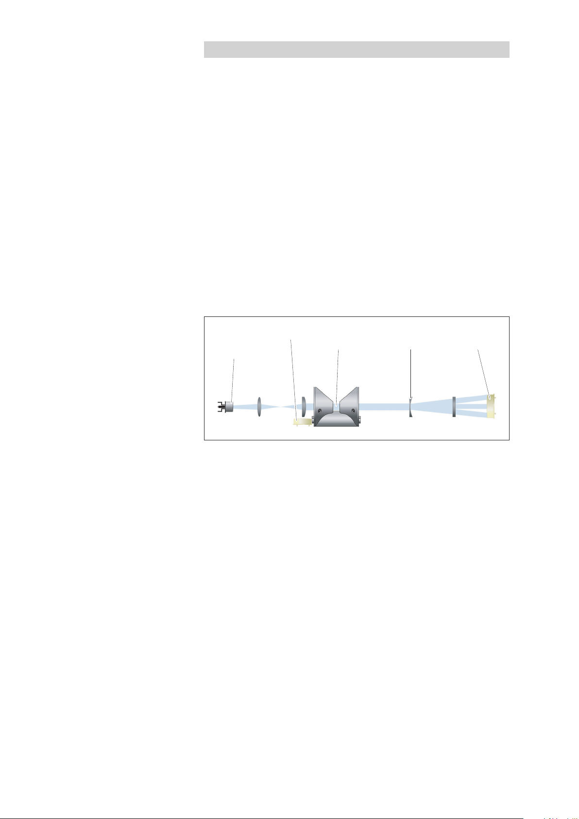
Light source
(Xenon-
flash light)
Reference diode Optical
path
Optical
lenses
Detectors
(3 x)
The OTT ecoN is a measuring instrument for continuous determination of the
nitrate content of ground and surface water.
The following nitrate concentrations in water can be determined:
NO3-N
NO
3
NOX-N1) (calibrated with standard NO3solution)
Figure 1 provides a schematic illustration of the measuring principle: A Xenon
flash lamp acts as a broad band light source. The light beam first passes through
an initial lens system, then passes through the measuring medium (water) in the
optical path, followed by a second lens system and is then received by three
detectors, which are photo diodes equipped with wavelength-specific filters. The
light beam at a wavelength of 212 nm is attenuated according to the nitrate content in the measuring medium. A reference diode before the optical path determines the unattenuated light output. This compensates for a fluctuating or deteriorating light source output. The additional attenuations measured at wavelengths of
254 nm and 360 nm also enable the OTT ecoN to compensate for organic interference or turbidity of the water.
1)
NO
(calibrated with standard NO3solution)
X
Fig. 1: Optical measuring principle of the
OTT ecoN UV Nitrate Sensor.
To cover a nitrate measuring range of 0 to almost 900 mg/L with high precision
and resolution, the OTT ecoN is available with six different optical path lengths
(= measuring ranges; 0.3 - 10 mm).
The electrical connection to a data logger or a controller is via the permanently
installed connecting cable with M12 industrial connector. An RS-485 interface
with Modbus (RTU) transmission protocol is available for this purpose.
The nitrate sensor is equipped with an integrated web interface for setting the
operating parameters on the OTT ecoN. To use this, the OTT ecoN must be temporarily connected to a PC using an interface box. Any internet browser can be
used as the user interface.
The measuring windows are equipped with anti-fouling technology with nano-coated glass keeping the windows largely free of dirt deposits. At problematic measuring points with high organic interference, the nitrate sensor can also be fitted with a
mechanical wiper. The wiping movements can be set to any time interval (externally
controlled).
1)
Combined value for nitrate and nitrite, where both nitrate and nitrite are present in the water to be
measured. Differentiation between nitrate and nitrite is not possible with the OTT ecoN. The combined
values can be internally scaled using a factor if required.
8

The OTT ecoN can be installed in different ways: Suspension in an observation well,
Optical path
Housing tube
(top)
Housing tube
(bottom)
Measuring window
Mounting rod
Shackle
Connecting cable
attached to a suitable substrate with fastening clips or attached to a float.
Maintenance work, cleaning, zero point checking and checking the reference values
/ quality index can be carried out by support staff themselves. The nitrate sensor can
be calibrated either in the factory by the OTT repair centre or by trained specialist
personnel with the appropriate equipment.
Fig. 2: Overview of
OTT ecoN UV Nitrate Sensor.
9

5 Installing the OTT ecoN
The OTT ecoN can be installed in three different ways depending on the specific
application:
suspended in an observation well see 5.1
attached to a suitable substrate with fastening clips see 5.2
attached to a float see 5.3
With all installation types, note the following:
the optical path must always be completely under water;
there must be an unobstructed inflow of water in the optical path;
the inflow direction should be at right-angles to the optical path (see Figure 3);
the connecting cable may not be used for attaching or suspension; it may not
be subjected to any mechanical load in addition to its own weight!
contact between the sensor and the ground is to be avoided; risk of damage.
installation should be carried out in such a way that the OTT ecoN can be tem-
porarily uninstalled for maintenance without excessive work;
the measuring windows must be completely free of air bubbles after immersion;
the salt content of the water to be measured may not exceed 1 PSU
➝ no measurement is possible in seawater, brackish water, mining waste water
with a high salt content, ... .
1)
1,77 mS/cm at 20 °C
1)
Fig. 3: Inflow direction.
10

5.1 Installing in an observation well
Suspend the OTT ecoN on a non-corroding chain or a stainless steel cable. To
do this, attach the chain/cable to the mounting rod with a shackle.
Suspend the connecting cable on the chain/cable with an ISO anchor clamp or
with cable ties.
Recommended minimum diameter of observation well: 4 inches.
Fig 4: Suspending the OTT ecoN
in an observation well.
11

5.2 Installing with fastening clamps
Attach the OTT ecoN to a suitable substrate with fastening clips and the
enclosed installation accessories (see "Accessories"). Attach the fastening clips
as closely as possible to the ends of the sensors. The substrate should be noncorroding.
Attach the connecting cable with cable clamps or install in a cable duct.
Fig. 5: Installing the OTT ecoN
with fastening clamps.
12

5.3 Installing on a float
This is the preferred installation type for surface water with significant fluctuations
in the water level
Attach the OTT ecoN to the float (see "Accessories") as shown in Figure 6.
Attach the fastening clamps as closely as possible to the ends of the sensors.
Secure the float against drifting with non-corroding chains or stainless steel
cables.
Attach the connecting cable to the chain/cable with cable ties.
Fig. 6: Installing the OTT ecoN on a float.
13

5.4 Electrical connection
Connecting cable
red +12 … +27 V
DC
blue GND
brown RS-485 D+ (B)
white RS-485 D– (A)
not used
Braided shield
Supply voltage + 12 … + 24 VDC(±10 %)
Power consumption max. 7 W
Notes:
Before electrical connection to a data logger/controller, the OTT ecoN
operating parameters must be set; see Chapter 6.
Do not shorten the OTT ecoN connecting cable or remove the M12 connector.
Connect using the connecting cable with open ends and M12 socket (see
"Accessories").
For cable lengths > 10 meters (with extension cable), the supply voltage
must be + 24 V
(voltage drop).
DC
Fig. 7: Wire assignment in connecting
cable with open ends.
Risk of damage to the OTT ecoN
The supply voltage must be connected with the correct polarity. Check this
before applying the supply voltage.
Connect the connecting cable with open ends (M12 socket) to the OTT ecoN
connecting cable (M12 connector). Please note: The M12 industrial connectors
are not pressure water tight ➝ Not suitable for use under water (degree of protection: IP 67).
Connect the red wire to the supply voltage (+12 … 24 VDC).
Connect the blue wire to earth (GND).
Connect the brown wire to the RS-485 (B) interface on a Modbus master.
Connect the white wire to the RS-485 (A) interface on a Modbus master.
If required: connect braided shield.
With electrically isolated OTT ecoN and Modbus master voltage supplies: Also
loop the earth (GND) connection through to the RS-485 interface.
14
The OTT ecoN is ready to operate as soon as the supply voltage is switched on.
Note: When connecting an OTT ecoN that is not continuously supplied with
voltage to an OTT netDL, a boot up time of 90 seconds is required!

6 Setting the operating parameters
The sensor is equipped with an integrated web interface for setting the operating
parameters on the OTT ecoN. To use this, the OTT ecoN must be temporarily connected to a PC using an interface box (see "Accessories"). Any internet browser
can be used as the user interface.
6.1 Connecting the OTT ecoN to a PC
Required accessories:
Power adapter
RJ45 patch cable (Ethernet cable)
G2 interface box
1)
included with the G2 interface box
Note: When setting the operating parameters, the voltage supply to the
OTT ecoN comes from the G2 interface box.
Connect the M12 connector on the OTT ecoN connecting cable to the G2 inter-
face box.
Connect the power adapter to the G2 interface box and plug into a mains outlet.
Wait for 3 seconds.
Connect the G2 interface box to a free Ethernet port (RJ45 socket) on a PC
using the RJ45 patch cable. (Alternatively, connection using an Ethernet switch
or router with DHCP server is possible.)
1)
1)
Fig. 8: Connecting the OTT ecoN to a PC.
15

6.2 Calling up the OTT ecoN web interface
Note: The Ethernet interface on the PC must be configured to automatically obtain
the required network settings (DHCP protocol).
Start any internet browser on the PC.
In the browser, enter one of the following:
– http://ecoN.ott/
– http://ecoN_serial number/
– http://192.168.77.1/
and press enter ➝ The home page of the OTT ecoN user interface opens (in
English).
Fig. 9: OTT ecoN user interface.
Web interface menu structure
"Overview"
– Information about the OTT ecoN
– Information about the Xenon flash lamp
"Calibration"
– This function is reserved exclusively for OTT service personnel or specially
trained users; "Login" and "Password" required
"Data Logger"
– Simple, internal data logger;
the sample/storage interval is 30 seconds;
– "Clear" clears and formats the internal memory
– "Download" copies the measured values recorded in the selected period
("Start date" to "End date") to the PC
"Measurement"
–"Parameter": shows the measured results from the last measurement in a table
– "Measure now!": starts instantaneous value measurement
– "Settings": allows you to enter an offset value and scaling factor and to
calculate a sliding mean value over "n" measured values
– "Edit"
"Comment": enter any informative comments
"Automatic": activates/deactivates automatic measurement (must be activated
in combination with an OTT netDL or Sutron datalogger!)
"Interval [s]": sample/storage interval is 30 seconds;
"Pheripherals"
– RS-485 interface parameters; factory default setting: "Modbus RTU", "9600",
"none", "none", "1";
– "Address": Modbus address; factory default setting: "1"
16

"System"
– "Common Settings", "Description": e.g. station name/description
– "Current Date and Time": internal date and time on the OTT ecoN
– "Recovery Point": this function is reserved exclusively for OTT service person-
nel or specially trained users; "login"/"password" required
– "System Log": Log file containing measurements performed, changes to the
operating parameters and error messages. "Download!" copies the log file to
the PC.
Explanations of reference measured values
"Measurement" | "Parameter" function
SQI Sensor-Quality-Index, specifies the quality of a measurement:
1,0 … 0,8 ➝ OK
0,8 … 0,5 ➝ Marginal
< 0,5 ➝ Error, see Chapter 8.4
RefA Light intensity on the 212 nm channel; this value should always be
higher than 150, otherwise insufficient light reaches the specific detector.
RefB Light intensity on the 254 nm channel; this value should always be
higher than 150, otherwise insufficient light reaches the specific detector.
RefC Light intensity on the 360 nm channel; this value should always be
higher than 150, otherwise insufficient light reaches the specific detector.
RefD specifies the light intensity of the Xenon flash lamp; this value should
always be higher than 13 000.
For further information on evaluating the reference measured values,
see Chapter 8.4.
17

7 Modbus protocol (RTU)
7.1 Prerequisites
Connection via RS-485 interface
Transmission parameters data bits: 8; parity: none; stop bits: 1 (8N1)
Transmission speed 9600 bps
Operating parameter "Measurement |"Automatic" Combined with OTT netDL: activated
Note: When connecting the OTT ecoN to an IP Datalogger OTT netDL, the OTT netDL configuration is limited on using
Modbus function "Read Holding Registers" (0x03).
7.2 "Read Holding Registers" (0x03) / "Write Multiple Register" (0x10) functions
Register-
Register name
Bus address 0000 unsigned word 1 … 247 1 R/W –
Serial number 0010 unsigned word 10 Byte; ASCII-Format – R –
Firmware version 0015 unsigned word 10 Byte; ASCII-Format – R –
Measured value
-N
NO
3
number Type Value range
1000
1500
float
1)
1 mm: 0.5 … 60
10 mm: 0.05 … 6
Factory
setting
Accessmode Unit
R [mg/L]
scaled value
Measured value NO
scaled value
Spectral quality
3
1002
1502
1004
float
float
1)
1)
1 mm: 2.2 … 266
10 mm: 0.22 … 26.6
R [mg/L]
0 … 28 000 R [1]
index SQI
scaled value
Light intensity
1504
1006
float
1)
0 … 28 000 R [1]
212 nm; RefA
scaled value
Light intensity
1506
1008
float
1)
0 … 28 000 R [1]
254 nm; RefB
scaled value
1508
Light intensity
360 nm; RefC
scaled value
Light intensity
reference diode, RefD
scaled value
1)
Byte sequence: AB CD (Big Endian)
18
1010
1510
1012
1512
float
float
1)
1)
0 … 28 000 R [1]
0 … 28 000 R [1]

7.3 "Write Single Registers" function (0x06)
Writing the value "0x0101" into the register "0x0001" starts a single measurement. Afterwards the measured values can be read out via function "Read
Holding Registers".
7.4 "Report Server ID" function (0x11)
This function outputs the sensor name, the serial number and the firmware version
each "null terminated".
19

8 Maintenance
8.1 Cleaning the OTT ecoN
Recommended interval: every 12 months
With problematic local measuring point conditions
(organic interference or water turbidity):
Every 4 to 6 months as required. Tip: After initial installation, check the sensor at short intervals and adjust the
cleaning interval according to specific requirements.
Required equipment:
Risk of damage to the OTT ecoN
Do not use any chemicals other than those specified here.
Do not use abrasive cleaning agents or objects.
Clean the measuring window with the utmost care.
Protect the M12 socket on the connecting cable from moisture!
CAUTION Risk of injury to the skin/eyes/respiratory system due to acetone
and acids
soft brush, sponge
mild soap solution
if required: Citric /acetic acid solution (10 %)
if required: Oxalic /ascorbic acid solution (5 %)
lint free cloth / paper cloth / optical wipe
Acetone
Ultra pure water
Improper handling of acetone and acid can lead to minor to moderately
severe injuries, particularly damage to
– Skin: Dryness (acetone: degreasing effect) skin changes, skin damage,
chemical burns;
– Eyes: Cornea damage, irritation, chemical burns;
– Respiratory system (inhalation): Irritation, fatigue, headaches, dizziness, nau-
sea/vomiting, acetone in higher doses has an anaesthetic effect
Wear laboratory gloves and protective goggles to perform cleaning.
Ensure adequate ventilation and do not inhale acetone vapour!
Uninstall the OTT ecoN.
Clear adherent dirt: Soak the OTT ecoN in a mild soap solution for several
hours.
If required: Remove any residual dirt with a soft sponge or brush.
For lime scale deposits: Place the OTT ecoN in a 10 % citric acid or acetic acid
solution for approx. 15 ... 30 minutes.
For brown deposits (iron or manganese oxide): Place the OTT ecoN in a 5 %
oxalic acid or 10 % ascorbic acid solution for approx. 15 ... 30 minutes.
Thoroughly rinse the OTT ecoN with tap water.
Clean the measuring windows: Soak a lint free cloth/paper cloth/special opti-
cal wipe with a few drops of acetone (see "Accessories") and carefully wipe off
both measuring windows; see Figure 10.
20

Fig. 10: Cleaning the
OTT ecoN measuring windows.
Recommendation: Rinse the optical path and measuring windows with ultra
pure water.
Allow the OTT ecoN to dry.
Polish the measuring windows with a dry lint free cloth/paper cloth/special
optical wipe.
Recommendation: Check the zero point; see Chapter 8.3.
Re-install the OTT ecoN, see Chapter 5.
8.2 Checking the OTT ecoN zero point
Recommended interval: after each cleaning;
earlier if implausible measured values occur
Required accessories:
VALtub 10 or 50 mm length; see "Accessories"
Alternative to VALtub: Suitable clean vessel in which the OTT ecoN can be
placed in a slightly inclined position
Ultra pure water (≥ 18,2 MΩcm)
Ambient temperature: 20 °C
Ultra pure water temperature: 20 °C
Note After cleaning the OTT ecoN, do not touch the measuring windows or the
housing in the area of the optical path. Wear clean laboratory gloves to check the
zero point. If impurities are detected in the ultra pure water when checking the
zero point, the water must be replaced.
21

Thoroughly clean the OTT ecoN; see Chapter 8.1.
Connect the OTT ecoN to the PC; see Chapter 6.1.
Fit a compatible VALtub on the OTT ecoN housing tube, see Figure 8.
Fig. 8: Checking the OTT ecoN
zero point – VALtub.
Pour ultra pure water into the VALtub. The measuring windows must be com-
pletely under water.
Pour away the ultra pure water after approx. 10 minutes.
Pour fresh ultra pure water into the VALtub; the measuring windows must again
be completely under water. There may not be any air bubbles on the measuring windows.
Call up the OTT ecoN web interface, see Chapter 6.2.
Perform a measurement: Call up the "Measurement" | "Parameter" | "Mea-
sure now!" ➝ the OTT ecoN starts a measurement and displays the result in the
browser window.
If the measured values are lower than
4.0 mg/L NO3-N with 1 mm path length
0.4 mg/L NO3-N with 10 mm path length
the zero point is OK!
If the values are equal to or higher than that figure, the OTT ecoN needs to be
recalibrated, see Chapter 8.3!
8.3 Calibrating the OTT ecoN
The nitrate sensor can be calibrated either in the factory by the OTT repair centre
or by trained specialist personnel with the appropriate equipment.
For calibration, directly contact the OTT Hydromet GmbH repair centre (see
Chapter 9) or the sales office responsible for your area.
22

8.4 Checking OTT ecoN reference values
The OTT ecoN has 5 reference measured values, which can be used to check
correct functioning of the device:
Sensor-Quality-Index: – SQI
Light intensities: – RefA (Wavelength 212 nm)
– RefB (Wavelength 254 nm)
– RefC (Wavelength 360 nm)
– RefD (Reference diode)
For detailed information on the reference measured values, see Chapter 6.2.
Recommended checking interval: if implausible measured values occur.
RefD < 13 000?
The light intensity of the xenon flash lamp is too low (ageing process)
➝ Send the OTT ecoN to the OTT Hydromet GmbH repair centre.
RefD > 13 000 and RefA, RefB, RefC < 150?
➝ Take sensor out of water and perform measurement with air
Values identical? ➝ Thoroughly clean sensor, see Chapter 8.1 and measure
with air again
Values identical? ➝ Check zero point, see Chapter 8.2.
Values identical? ➝ Send OTT ecoN to OTT Hydromet GmbH repair centre;
see Chapter 9
In ultra pure water: RefA, RefB, RefC = RefD ± 5000 ➝ OK
In ultra pure water: RefA, RefB, RefC = RefD ± 5000 and
in measuring medium: RefA, RefB, RefC < 150
➝ Send OTT ecoN to OTT Hydromet GmbH repair centre; see Chapter 9.
23

9 Repairs
In the event of a device malfunction, check whether you can resolve the fault
yourself using Chapter 8.4. „Checking OTT ecoN reference values“.
If the device has a defect, please contact the OTT repair centre:
OTT Hydromet GmbH
Repaircenter
Ludwigstraße 16
87437 Kempten · Germany
Phone +49 831 5617-433
Fax +49 831 5617-439
repair@ott.com
Please note: Only have a defective OTT ecoN checked and/or repaired by the
OTT repair center Never attempt to repair the unit yourself. Any repairs or
attempted repairs carried out by the customer will void any warranty.
10 Notes about the disposal of old units
Within the member countries of the European Union
In accordance with the European Union guideline 2002/96/EC, OTT takes back
old devices within the member countries of the European Union and disposes of
them in an appropriate way. The devices concerned by this are marked with the
symbol shown aside.
For further information on the return procedure, please contact your local sales
contact. You will find the addresses of all sales partners in the internet on
„www.ott.com“. Please take into consideration also the national implementation
of the EU guideline 2002/96/EC of your country.
For all other countries
After decommissioning, dispose of the OTT ecoN properly.
Observe the regulations applicable in your country for disposal of electronic
devices!
Never dispose of the OTT ecoN with normal household waste.
Materials used
see Chapter 11 and Appendix B5
24

11 Technical data
Measuring technology
Ligth source Xenon flash lamp
Detector 4 photo diodes + filter
Measurement principle Attenuation (optical attenuation)
Optical path 0.3 mm
1 mm
2 mm
5 mm
10 mm
Parameter NO
NO
-N
3
3
NOX-N
NO
(calibrated with NO3standard solution)
X
Measuring range
0.3 mm optical path 1.65 … 200 mg/L NO
1 mm optical path 0.5 … 60 mg/L NO
2 mm optical path 0.25 … 30 mg/L NO
5 mm optical path 0.1 … 12 mg/L NO
10 mm optical path 0.05 … 6 mg/L NO
-N
3
-N
3
-N
3
-N
3
-N
3
Measuring accuracy
0.3 mm optical path ±(5 % + 3.3 mg/L) NO
1 mm optical path ±(5 % + 1.0 mg/L) NO
2 mm optical path ±(5 % + 0.5 mg/L) NO
5 mm optical path ±(5 % + 0.2 mg/L) NO
10 mm optical path ±(5 % + 0.1 mg/L) NO
-N
3
-N
3
-N
3
-N
3
-N
3
Turbidity compensation Yes
Data logger ~ 2 GB
T
Response Time 20 s
100
Measurement interval ≥ 10 s
Housing material Stainless steel (1.4571/1.4404)
Dimensions (L x Ø) Approx. 470 x 48 mm (with 10 mm path)
Weight Approx. 3 kg
Interfaces digital Ethernet (TCP/IP)
RS-485 (Modbus RTU)
Power consumption ≤ 7 W
Power supply 12 … 24 V
(±10 %)
DC
Maintenance effort typ. ≤ 0.5 h/month
Calibration/maintenance interval 24 months
System compatibility Modbus RTU
Max. pressure
with Subconn 30 bar
with fixed cable 3 bar
Protection type IP68
Sample temperature +2 … +40 °C
Ambient temperature +2 … +40 °C
Storage temperature –20 … +80 °C
Inflow velocity 0.1 … 10 m/s
25

12 Measuring range, limits, accuracy depending on path length
Path length Measuring parameter Measuring range Detection limit Determination limit Precision Accuracy
[mm] [mg/L] [mg/L] [mg/L] [mg/L] [mg/L]
0.3 Nitrate NO
Nitrate NO
1 Nitrate NO
Nitrate NO
2 Nitrate NO
Nitrate NO
5 Nitrate NO
Nitrate NO
10 Nitrate NO
Nitrate NO
1)
Relative to a standard calibration solution; comment: 1 mg/L NO3-N corresponding to 4.43 mg/L NO3
-N 0 … 200 1.65 4.95 0.495 ±(5 %+3.3)
3
0 … 886 7.26 21.78 2.178 ± (5%+14.5)
3
-N 0 … 60 0.5 1.5 0.15 ±(5 %+1)
3
0 … 266 2.2 6.6 0.66 ± (5%+4.4)
3
-N 0 … 30 0.25 0.75 0.075 ±(5 %+0.5)
3
0 … 133 1.1 3.3 0.33 ± (5%+2.2)
3
-N 0 … 12 0.1 0.3 0.03 ±(5 %+0.2)
3
0 … 53 0.44 1.32 0.132 ± (5%+0.88)
3
-N 0 … 6 0.05 0.15 0.015 ±(5 %+0.1)
3
0 … 26,6 0.22 0.66 0.066 ± (5%+0.44)
3
1)
26

Appendix A – Dimensions
all dimensions in mm
153.5
469
557
AF20
Ø 48.3
28
27

Appendix B – Accessories: Mechanical wiper
OTT ecoN UV nitrate sensors with path lengths (measuring ranges) of 1, 2, 5 and
10 mm can be equipped with an optional mechanical wiper (see "Accessories")
for cleaning the optical path.
Depending on the path length, a corresponding wiper shaft and a wiper blade
are required (see "Spare parts/consumables").
The wiping operation (duration: approx. 2 ... 3 seconds) is started by connecting
the supply voltage. This causes a wiper blade fitted with several rubber lips to
rotate twice through the optical path and remove any deposits on the measuring
windows of the OTT ecoN. The wiper blade then moves to a park position outside
the optical path. To start another wiping operation, the supply voltage must be
disconnected for at least 1 second.
The mechanical wiper is installed by fitting and screwing two housing sections
onto the OTT ecoN housing tube.
The mechanical wiper has a separate, permanently installed connecting cable with
M8 industrial connector; length: 10 metres. To connect to the supply voltage, a
corresponding connecting cable (length: 1.5 metres) with open ends and M8 socket is available (see "Accessories").
Fig. B1: Mechanical wiper, installed on
housing tube of OTT ecoN UV nitrate sensor.
28

B1 – Preparing the mechanical wiper
O-ring
Recess
Wiper shaft
Hole
Tor x - ke y
Cover
This requires a wiper blade set appropriate for the path length (measuring range)
of the OTT ecoN; see "Spare parts/consumables".
Risk of damage to the OTT ecoN
Observe the path length of the OTT ecoN: only install a corresponding wiper
shaft with associated wiper blade.
Installing the wiper shaft and wiper blade:
Lightly grease the O-ring on the wiper shaft with the lubricating grease supplied.
Align the wiper shaft and insert in the hole. If necessary, slightly rotate the
wiper shaft so that it can be fully inserted. The O-ring must then be located
inside the hole.
Fig. B2: Installing the wiper shaft.
Fig. B3: Wiper shaft installed.
29

Position the cover on the wiper shaft and attach it with the screws and Torx key
Wiper blade
supplied.
Fig. B4: Attaching the cover.
Align the wiper blade (see figure) and slide it onto the wiper shaft until it locks
into place (clicking sound).
Fig. B5: Fitting the wiper blade.
30

B2 – Installing the mechanical wiper on the OTT ecoN
Adjusting screw
Lower housing section
Hexagon
socket screw (4 x)
Upper
housing section
Holes
Align the lower housing section (holes must line up) and place on the housing
tube of the OTT ecoN.
Attach the lower housing section to the OTT ecoN using the adjusting screw.
Fit the upper housing section on the OTT ecoN housing tube and attach using
the four hexagon socket screws supplied (size: 2.5 mm).
Fig. B6: Installing the mechanical
wiper on the OTT ecoN.
B3 – Electrically connecting the mechanical wiper
The connecting cable for the mechanical wiper is factory assembled for connection
to a switched supply voltage. Switching on the supply voltage starts the wiping
operation. If necessary, you can alternatively supply the mechanical wiper with a
constant voltage and start the wiping operation using a short trigger pulse.
Operating parameters for mechanical wiper:
Supply voltage +12 … + 24 V
Power consumption max. 6 W
Wiping operation duration approx. 2 to 3 seconds
Gap between two wiping operations > 1 second
Recommended wiping interval 1 x daily
Trigger pulse length 100 ms
Trigger signal voltage range +5 … + 24 V
DC
DC
Note: The supply voltage must be applied until the end of a wiping operation. A
wiping operation is made up of two wiping cycles. The wiper blade is then in park
position. Otherwise the wiper blade may still be in the optical path, which leads to
unusable measurements.
31

Connect the connecting cable with open ends (M8 socket) to the mechanical
+12 … +24 V
DC
Earth
wiper connecting cable (M8 connector). Please note: The M8 industrial connectors are not pressure water tight ➝ Not suitable for use under water
(degree of protection: IP 67).
Connect the brown/white wire to the switched supply voltage (+).
Connect the blue/black wire to earth.
Alternative (with trigger pulse):
– Remove double wire end ferrules;
– Fit four individual wires with wire end ferrules;
– Connect the brown wire to the continuous supply voltage (+);
– Connect the blue wire to earth;
– Connect the white wire (+) to a controller with trigger output;
– Connect the black wire (-) to a controller with trigger output.
Fig. B7: Wire assignment in connecting
calbe with open ends.
Testing the wiping operation: Connect the supply voltage (alternatively trigger
pulse) ➝ The wiper blade must rotate twice through the optical path; the rubber lips of the wiper blade must slide over both measuring windows with light
contact. The wiper blade must then move to the park position.
32

B4 – Changing the wiper blade
Locking mechanism
Wiper blade
Wiper shaft
Check the wiper blade at regular intervals. If there are any signs of scoring or
material abrasion on the rubber lips, it must be replaced.
A wiper blade set contains 5 wiper blades (see "Spare parts/consumables").
When all wiper blades in a set are worn, you need a new set as in this case the
wiper shaft, O-ring and cover also need to be replaced. (The mechanical wiper
does not need to be detached from the OTT ecoN.)
Risk of damage to mechanical wiper (gearing)
Avoid mechanical loads on the wiper shaft and the wiper blade!
Never turn the wiper shaft by hand.
At every fifth wiper blade change: First uninstall the entire wiper shaft and then
install a new one; see Appendix B2.
Slightly lift the locking mechanism with a fingernail or a small slotted screwdriv-
er and pull the wiper blade forwards.
Align the new wiper blade (see Figure B8) and slide it onto the wiper shaft until
it locks into place (clicking sound).
Fig. B8: Changing the wiper blade.
33

B5 – Mechanical wiper technical data
Supply voltage 12 … 24 VDC(± 10 %)
Power consumption
active approx. 2 … 6 W
Standby
For use with path lengths 1 mm
Positive operating pressure max. 3 bar
Degree of protection IP 68
Inflow speed max. 10 m/s
Operating temperature +2 … +40 °C
Storage temperature –10 … +70 °C
Actuation
Connecting cable fixed connection, 10 metres; with 4-pin M8-
Trigger input 5 … 24 V
Trigger input power consumption 2 … 15 mA
Wiper operation duration ≤ 3 seconds
Dimensions L x Ø 175 mm x 80 mm
Weight 0.52 kg
Materials NBR, POM, TPE (PP, EPDM), V4A
1)
≤ 30 mW
2 mm
5 mm
10 mm
connector + connecting cable with M8-socket and open ends; 1.5 metres
(±10 % )
DC
1)
For continuously applied supply voltage and actuation using trigger signal
34

Appendix C – Note on Declaration of Conformity
If necessary, you can download the current version of the Declaration of
Conformity for the OTT ecoN from our website as a PDF file:
"www.ott.com/resources".
35

Document number
63.300.001.B.E 01-0918
OTT Hydromet GmbH
Ludwigstrasse 16
87437 Kempten · Germany
Telefon +49 831 5617-0
Telefax +49 831 5617-209
info@ott.com · www.ott.com
 Loading...