

Page 1
ICS Impulse USB
0 4 5 9
User Guide
Doc no.7-50-1490-EN/01
Part no. 7-50-14900-EN
Page 2

Copyrightnotice
No part of this documentation or program may be reproduced, stored in a retrieval system, or transmitted, in any form or
by any means, electronic, mechanical, photocopying, recording, or otherwise, without the prior written consent of Natus
Medical Denmark ApS.
Copyright© 2013, 2019, Natus Medical Denmark ApS
Published in Denmark by Natus Medical Denmark ApS
All information, illustrations, and specifications in this manual are based on the latest productinformation available at the
time of publication. Natus Medical Denmark ApS reserves the right to make changes at any time without notice.
Versionrelease date
2019-04-29
Technicalsupport
Please contact your supplier.
2 Otometrics - ICS Impulse USB
Page 3

Table of Contents
User Guide
1 Your New ICS Impulse System
2 Intended use
3 Typographical conventions
4 System startup and logging in
5 Patient data entry/lists
6 Preparing for testing
7 Adding remarks/adding video recording
8 Collecting Head Impulse data
9 Monitoring eye and head movement
10 Analyzing data for a single test
11 Analyzing data for multiple-tests
12 Workingwith reports
13 How to record and play back video
4
4
4
5
5
8
17
17
19
20
32
34
38
14 System settings
15 Installation and Setup
16 Accessories
17 Service, cleaning, and maintenance
18 Other references
19 Standards
20 Manufacturer
21 Warningnotes
22 Definition of symbols
23 Notes on EMC (Electromagnetic Compatibility)
Otometrics - ICS Impulse USB
43
45
52
53
54
54
56
56
58
59
3
Page 4

User Guide
1 Your New ICS Impulse System
Congratulations! You are now the owner of a sophisticated new ICS Impulse system developed in collaboration with Drs.
Ian Curthoys, Michael Halmagyi and others at University of Sydney.
To assist you in getting the most out of the ICS Impulse system, we have included a user guide, online reference manual
and a training video. We hope you find it easy to use and that your use of the incorporated tips and information results in
improved data collection accuracy as it relates to your assessment of vestibular-related disorders, test results, reporting,
and patient information retrieval.
1.1 Device description
ICS Impulse is a monocular video goggle with built-in gyroscopes that allow for the measurement of eye and head movement. The ICS Impulse is operated from the OTOsuiteVestibular software.
• With ICS Impulse you can perform the head impulse test
• With ICS Impulse you can assess the anterior, posterior and lateral semicircular canals
• With ICS Impulse you can video record the eye and the room (using the synchronized room video) and play back the
videos synchronously
2 Intended use
Users: to be used only by qualified medical personnel with prior knowledge of the medical and scientific facts underlying
the procedure.
Use: used in the assessment of patients with complaints of dizziness, disequilibrium, and vertigo. The assessment of the vestibular-ocular reflex (VOR) is performed by measuring, recording, displaying, and analyzing eye and head movements.
3 Typographical conventions
The use of Warning, Caution and Note
For safety reasons and appropriate use of the device and/or software, the manual contains Warnings, Cautions and Notes.
These headings are used as follows:
Warning• Indicates that there is risk of death or serious injury to the user or patient.
Caution• Indicates that there is a risk of injury to the user or patient or risk of damage to data or the device.
4 Otometrics - ICS Impulse USB
Page 5
Note• Indicates that you should take special notice.
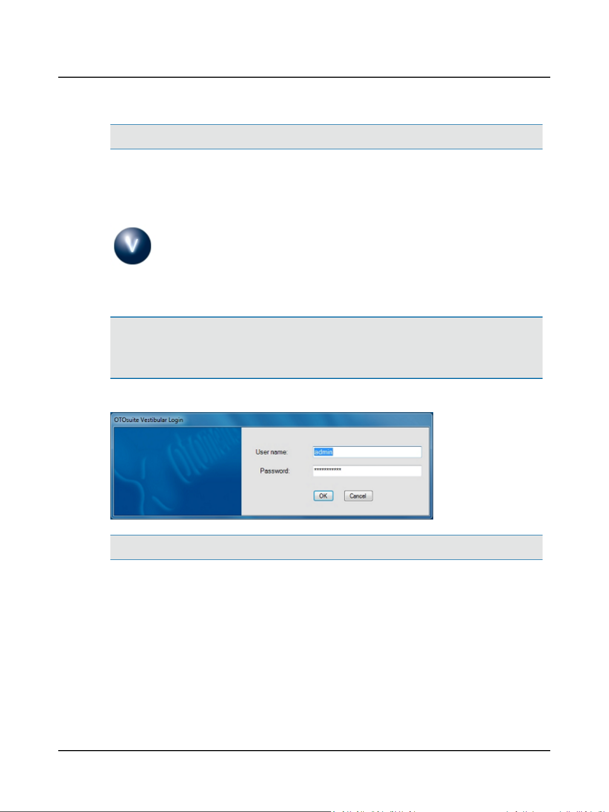
4 System startup and logging in
1. Switch on the computer.
2. Double-click the OTOsuiteVestibular icon.
Note• An Administrator user name and password are provided with a new installation of OTOsuiteVestibular. DO
NOT delete the user name or password from the login screen until at least one new user name with password has been
added. Ensure that at least one user has administrator privileges. For information on how to add new users, refer
toSet up a new user ► 43.
User Guide
At the login screen
Note• Both user name and password are case sensitive.
1. Enter your user name.
2. Enter your password and click OK.
For additional information about the OTOsuiteVestibular screen, entering test remarks, report findings, working with
patients lists, and logging out refer to the Reference Manual.
5 Patient data entry/lists
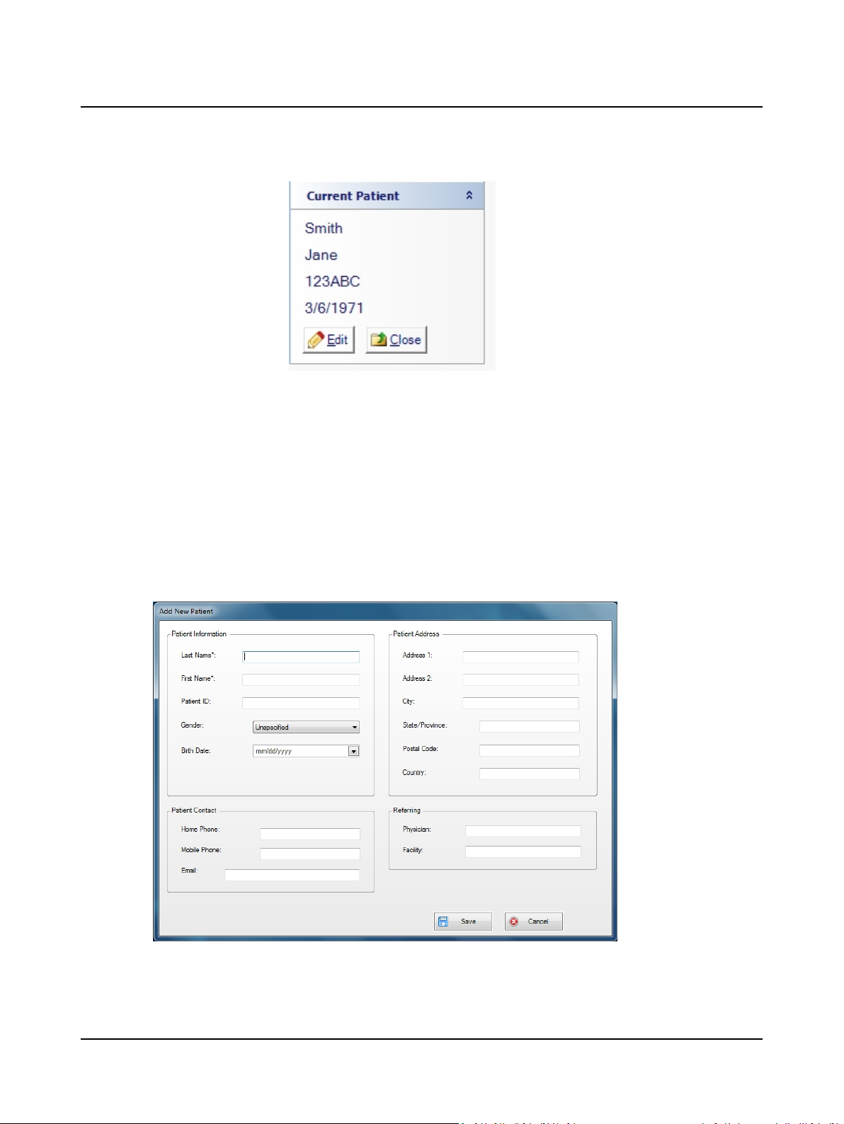
The Current Patient group provides information about the patient currently open.
Otometrics - ICS Impulse USB
5
Page 6
User Guide
• Last name
• First name
• Patient ID
• Date of Birth
• Click Edit to modify patient information
• Click Close to close the current patient and start a new temporary patient
If no patient is open, a temporary patient is available. The temporary patient allows testing to start without entering
patient data. The patient is given a unique number based on the date and time the patient record was created (yyyymmddhhmmss where yyyy=year, mm=month, hh=hour, dd-day, mm=minute, and ss=second).
Once data is saved, you will be prompted to edit the temporary patient information. For information about editing existing
patient information, refer to page ► 7.
Patients group
This group allows you to create a new patient or view a list of existing patients.
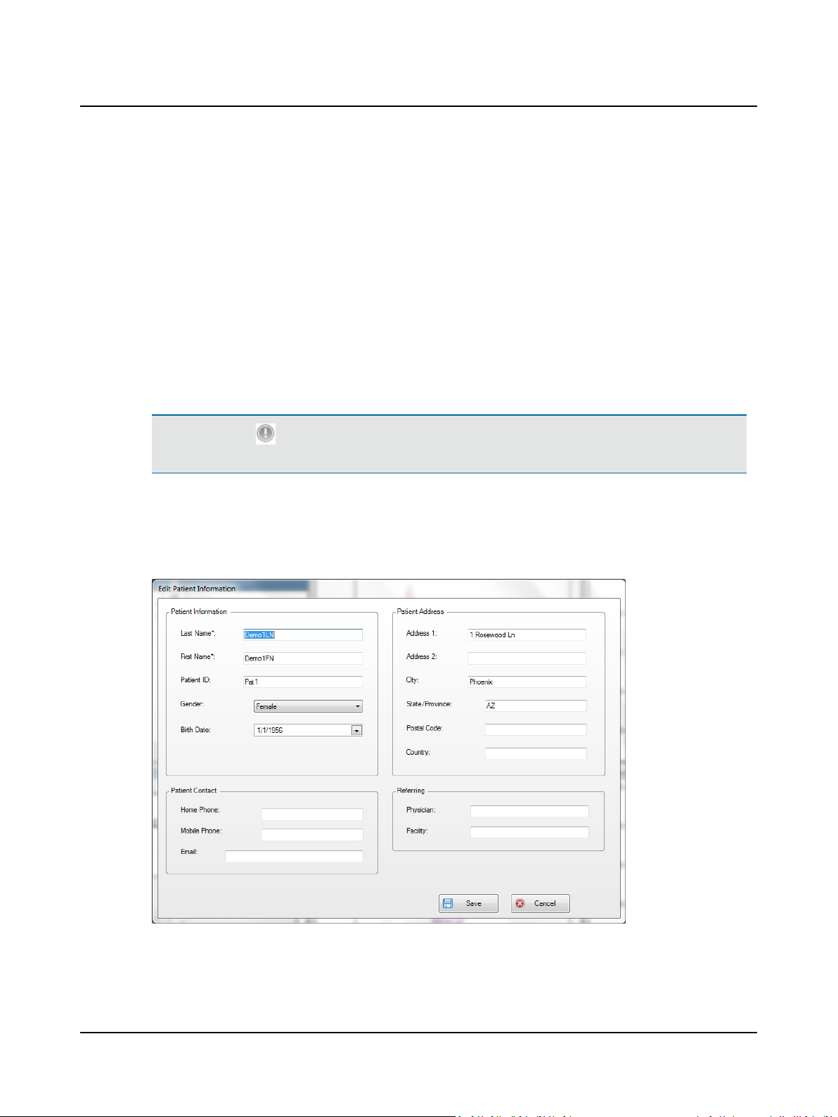
To enter information for a new patient, click New Patient and add patient information in the form:
• Entries that cannot be left blank are marked with an asterisk (*).
• For all entries the maximum number of characters is 45.
6 Otometrics - ICS Impulse USB
Page 7
User Guide
• Patient ID can be numeric, alphabetical or a combination of numbers and letters.
• To set the gender, click the down arrow and select the appropriate entry.
• The date of birth format is determined by the computer setup and will display as mm/dd/yyyy or dd/mm/yyyy where
mm=month, dd=day, and yyyy=year. Only numeric characters are allowed (alpha characters can not be used).
Existing patient
A complete description of patient list operations is provided inthe Reference Manual.
From the Patients group, click Patient List. The window that displays provides access to existing patients.
Each row has patient information separated into columns according to the type of information: Patient name, ID#, etc. The
HI (Head Impulse) and Video columns are blank or have check marksto indicate the following:
• HI - head impulse data is saved
• Video - video data is saved
Note• The symbol indicates the user has chosen to mark one or more tests or videos for a specific purpose (for
example,it may refer to abnormal results, results to be used for a study, etc.)
To select a patient, click the patient name.
• Click Open (or double-click) to open the patient to view test results
• Click Edit to make changes to the existing patient information
Modify patient information in this form:
Otometrics - ICS Impulse USB
7
Page 8
User Guide
6 Preparing for testing
6.1 The patient is prepared
Warning• A head impulse should not be performed on patients with a neck injury, or on patients who have been told
by their physicians to limit or avoid neck movement activity.
Prior to testing, provide the patient with these general recommendations:
• If in doubt, consult with a physician about the possible side effects of stopping a particular medication.
• Stop tranquilizers, sedatives, or vestibular suppressants for at least 48 hours before the test.
• Continue medications that are vital, such as insulin, heart medications, seizure medications, and possibly antidepressants.
• No alcohol for 48 hours before testing.
• Do not wear make-up around the eyes.
• Wear comfortable clothing.
6.2 The goggles are prepared
Observe the recommended guidelines regarding cleaning and maintenance for the goggles as described in Service, clean-
ing, and maintenance ► 53.
Note• The single-use, disposable face cushion should be replaced for each new patient.
1. To remove the face cushion, slightly flex the goggles out at the side opposite of the camera side and snap out the face
cushion. Release the face cushion from the other side.
2. Properly dispose of the used face cushion.
3. Obtain a new face cushion.
4. Align the tab of the face cushion with the hole on the camera side of the goggles.
5. Ensure the face cushion is inside the nose piece.
6. Slightly flex the goggles at the opposite side, align the tab of the face cushion with the hole on this side of the goggles.
7. Double check both sides are fully inserted by pressing in at each side.
6.3 Set up a proper test environment
The environment where the patient is tested can vary but must allow you to position the patient at least one meter from
the wall (or other solid surface that can be used as a projection surface.).
1. Choose a wall that allows you to position the patient at least one meter in front of the fixation dot.
2. Apply one of the fixation dots supplied with the system to the wall in a location that allows you to position the patient
directly in front of the fixation dot.
8 Otometrics - ICS Impulse USB
Page 9
6.4 Place goggles on patient
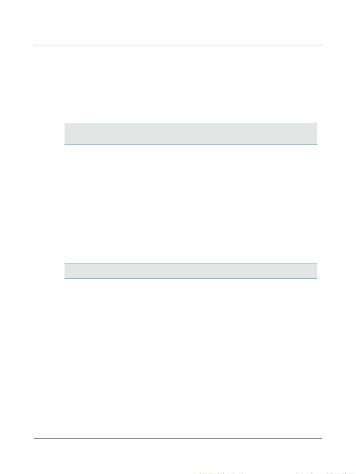
When goggles are placed properly they sit comfortably on the bridge of the nose and will not slip during the test. Poor
goggle fit resulting in slippage can result in gain values being inaccurate.
Note• You can find more information in the ICS Impulse training video or at www.icsimpulse.com.
Caution• Goggle Fit is Important. Improper goggle fit can result in inaccurate data collection. Goggle slippage often
results in inaccurate gain values (too high).
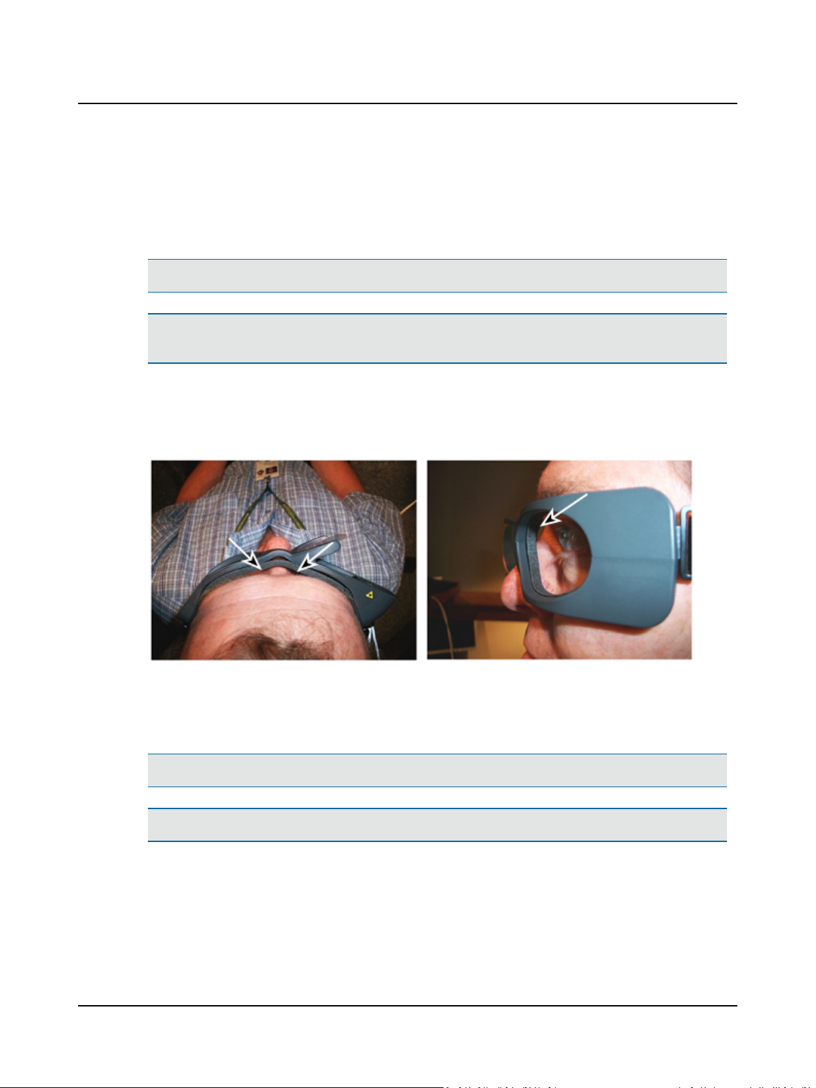
After placing the goggle on the patient and tightening the strap, look at how the goggle fits on the person's face. If there
are gaps between the goggle and the patient's face the goggle may slip.
Improper goggle fit
User Guide
1. Before putting the goggles on the patient ensure
– the goggles have a new unused face cushion. Refer to The goggles are prepared ► 8.
– the mirror is clean. Refer to Service, cleaning, and maintenance ► 53.
Note• The single-use, disposable face cushion must be replaced for each new patient.
Caution• Improper cleaning may scratch the mirror surfaces.
2. If required, replace the strap. Refer to Service, cleaning, and maintenance ► 53.
3. Position the goggles on the patient’s face over the bridge of the nose.
4. Bring the strap above the patient’s ears and around to the back of head.
5. Tighten the strap tight enough to ensure that goggles will not shift during testing.
Otometrics - ICS Impulse USB
9
Page 10
User Guide
6. Allowing some flexibility in the cables for head movement during testing, clip the cable clip to the patient’s clothing
at the top of the shoulder.
7. Ensure the eyes are wide open with eyelids positioned to not interfere with pupil detection. If required, adjust the
skin around the eye:
Tilt the bottom of the goggles out and away from the face, pulling the skin below the eye down and repositioning the
goggles to hold the skin in place. Tilt the top of the goggles out and away from the face, pulling the skin above the eye
up and repositioning the goggles to hold the skin in place.
8. Visually inspect goggle fit.
Proper goggle fit
6.5 Adjust system for correct pupil detection and tracking
6.5.1 Lateral test
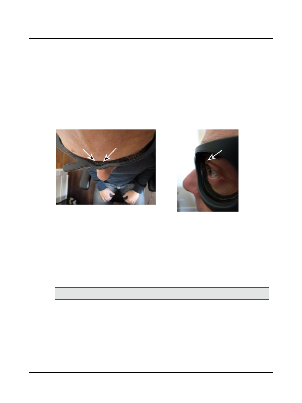
1. Choose the Impulse Type: Lateral.
2. For patients with spontaneous nystagmusor gaze-evoked nystagmus (evoked by gaze position during head impulse),
select the check box Spontaneous Nystagmus. By selecting this check box for a patient who has spontaneous nys-
tagmus or gaze-evoked nystagmus, it prevents good impulses from being rejected inappropriately.
3. Position the patient at least one meter in front the wall (refer to Preparing for testing ► 8 for information).
Note• The Center button is disabled when Lateral is the selected Impulse Type.
10 Otometrics - ICS Impulse USB
Page 11
4. Position the ROI (Region of Interest) around the pupil:
– click on the green box and drag to center it on the pupil, or
– click on the pupil to center the pupil inside the green box.
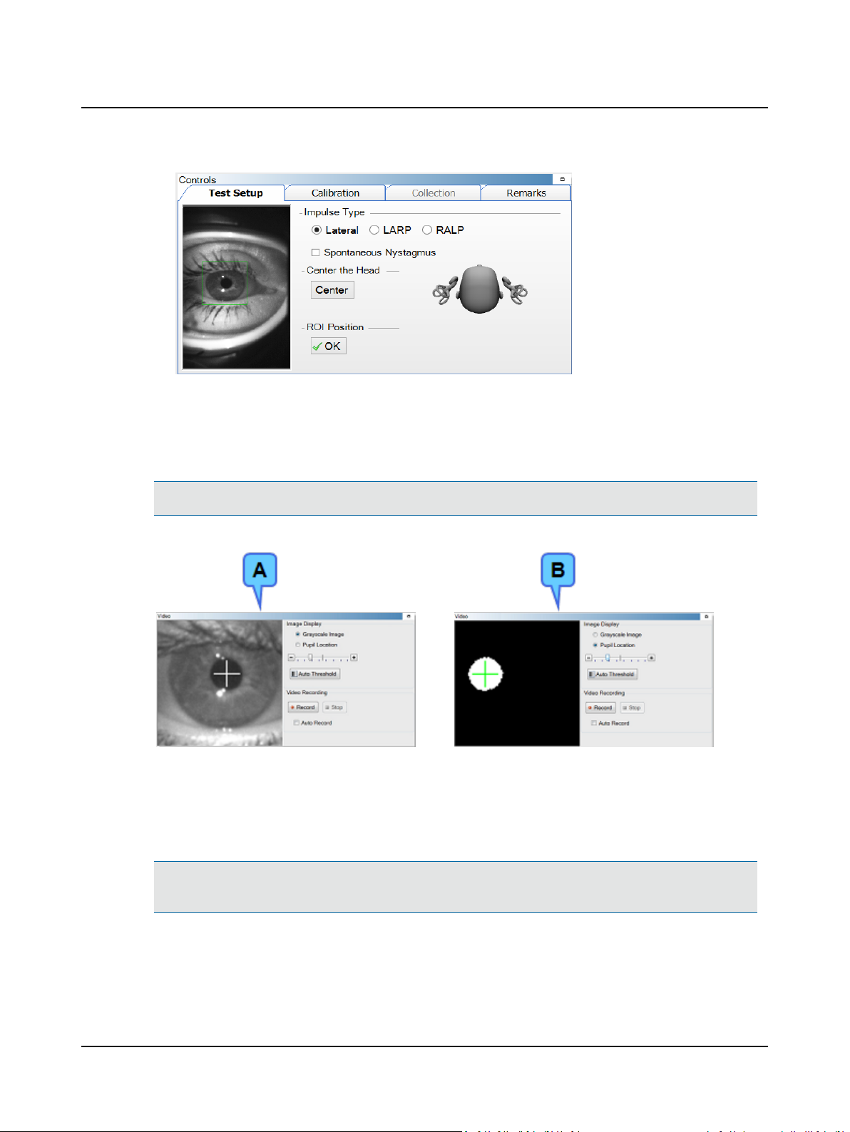
5. In the Videowindow, choose the type of image displayed: Grayscale Image (A) or Pupil Location (B).
Note• If video recording the eye, select Grayscale Image.
User Guide
6. If the pupil was not automatically detected, select Auto Threshold. The system centers the cross-hair on the pupil.
7. Ask the patient to stare at the fixation dot. Assess pupil tracking by observing the cross-hair: If the cross-hair fails to
track the pupil (jumps around and does not stay centered on the pupil), move the threshold slider to adjust.
Pupil detection ensures that the system tracks the pupil properly during calibration and when collecting data.
Note• When Image Display is set to Pupil Location, make additional adjustments to remove any white areas outside
the white circular image of the pupil.
8. Select OK to accept the ROI position.
9. Continue to (Calibrate ► 13).
Otometrics - ICS Impulse USB
11
Page 12
User Guide
6.5.2 LARP or RALP test
This procedure assumesthat the test is performed after the Lateral test.
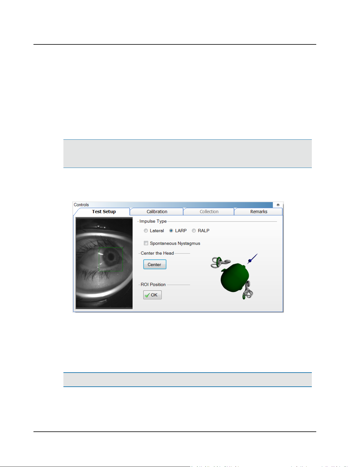
1. Choose the Impulse Type: LARP or RALP. Choosing the impulse type determines which plane of the gyroscopes (i.e.,
head trace) should be bold in the Real Time Trace. It also determines the shape of the training curves.
2. For patients with spontaneous nystagmusor gaze-evoked nystagmus (evoked by gaze position during head impulse),
select the check box Spontaneous Nystagmus. By selecting this check box for a patient who has spontaneous nys-
tagmus or gaze-evoked nystagmus, it prevents good impulses from being rejected inappropriately.
Note• Clicking Center sets the reference point used to provide feedback for head position during LARP/RALP testing.
The button is disabled if the setting for Head Position Feedback During LARP/RALP is disabled in the Options win-
dow. Please refer to the Reference Manual.
3. Ensure that the patient's head is not moving and that it is perfectly centered. Click Center.
4. Move the head to the right (LARP test) or to the left (RALP test) until the head and canals turn green on the head position feedback graphic.
5. Position the ROI (Region of Interest) around the pupil:
– click on the green box and drag to center it on the pupil, or
– click on the pupil to center the pupil inside the green box.
6. Ask the patient to stare at the fixation dot. Assess pupil tracking by observing the cross-hair: If the cross-hair fails to
track the pupil (jumps around and does not stay centered on the pupil), move the threshold slider to adjust.
7. Select OK to accept the ROI position.
Note• Calibration values calculated for the Lateral test remain valid for the LARP/RALP tests.
8. If a Lateral test was performed prior to starting this test, continue to (Collecting Head Impulse data ► 17).
12 Otometrics - ICS Impulse USB
Page 13
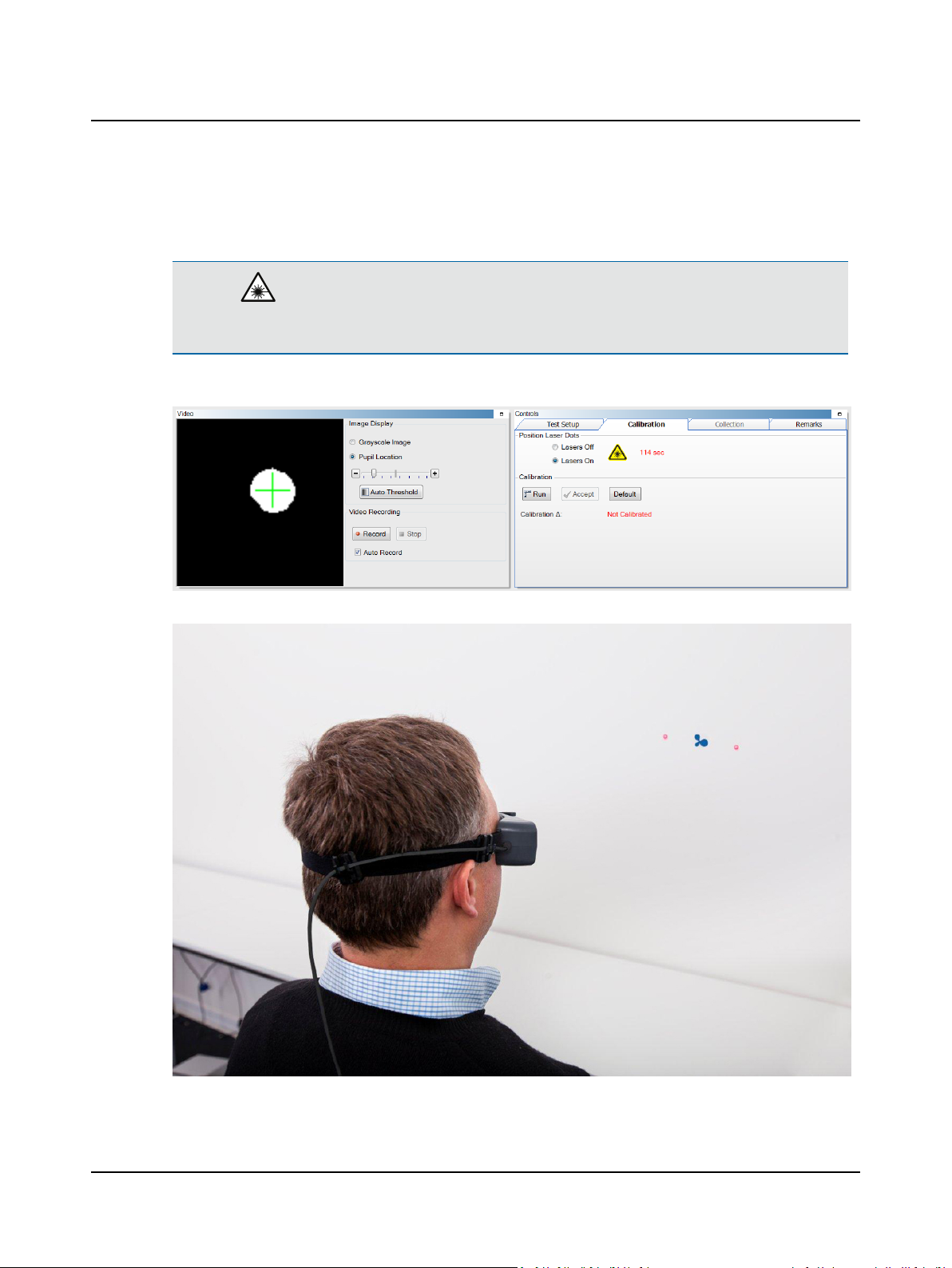
6.6 Calibrate
Caution• During this procedure both lasers will turn on. Do not look directly at the lasers. Use of controls or
adjustments, or performance of procedures other than those specified herein, may result in hazardous radiation exposure.
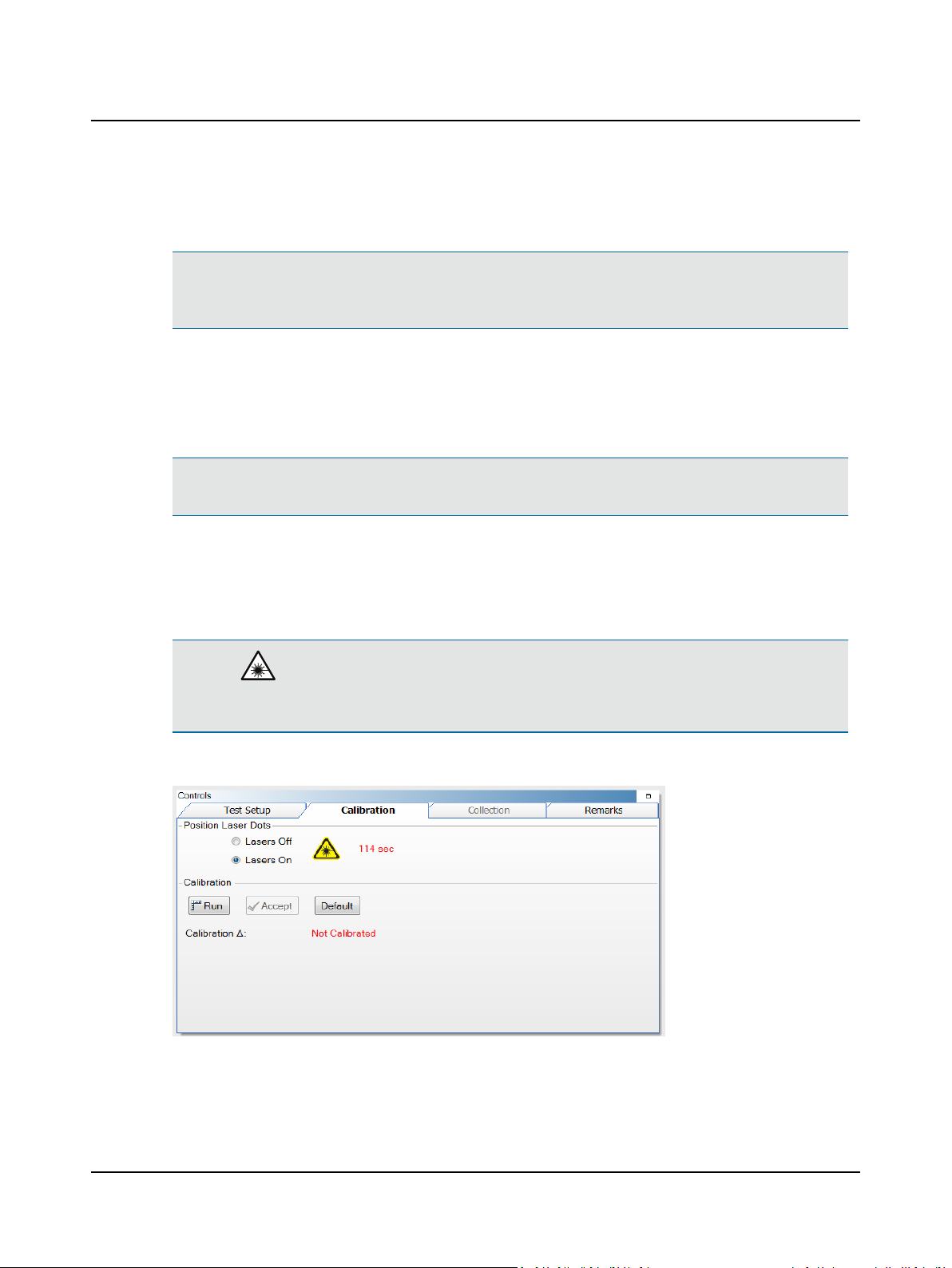
1. Click Lasers On to turn on both lasers.
User Guide
2. Ask the patient to position the left and right dots equidistant on each side of the fixation dot.
Otometrics - ICS Impulse USB
13
Page 14
User Guide
3. Ask the patient to look at the left dot, then at the right dot. In the Video window, check that the cross-hair continues
to track the pupil.
Note• Use the Real Time Trace window to monitor incoming data. By observing the head trace (orange/blue/pink)
and the eye trace (green), you can tell if the patient is moving their head or eyes (instead of staring at the fixation
dot), blinking excessively, or not following instructions being given (not cooperating).
4. If the cross-hair fails to track the pupil (jumps around and does not stay centered on the pupil), move the threshold
slider to make further adjustments.
In the calibration procedure, the patient is asked to switch their gaze between the two dots that appear when the
lasers are on. As the patient’s gaze switches, the system tracks the movement of the pupil.
Note• When a patient cannot be calibrated (for example the vision is so poor that the patient cannot see the fixation
dot or laser beams dots), click Default to use the calibration default values (∆ = 21).
The eye movement between the two laser beam dots is measured and calibrated against the known values between
the two laser beam dots. The calibration values relate to the pixel location that equates to 7.5 degrees left and right
of center. The difference between the left and right equates to the number of pixels for a 15 degree movement of
the eye. These values are used to analyze eye movement during the impulse testing.
Caution• During this procedure one laser at a time will turn on. Do not look directly at the lasers. Use of con-
trols or adjustments, or performance of procedures other than those specified herein, may result in hazardous radiation exposure.
5. Click Run.
6. Ask the patient to face the fixation dot and hold the head still.
7. Ask the patient to follow the laser beam dot.
14 Otometrics - ICS Impulse USB
Page 15

User Guide
The calibration values are automatically saved. The stored calibration value can be used for all 3 head impulse tests:
Lateral, LARP, RALP. There is no need to recalibrate between tests unless the goggles have moved. If you exit out of
the patient’s file and reopen, calibration will need to be performed again.
Calibration check
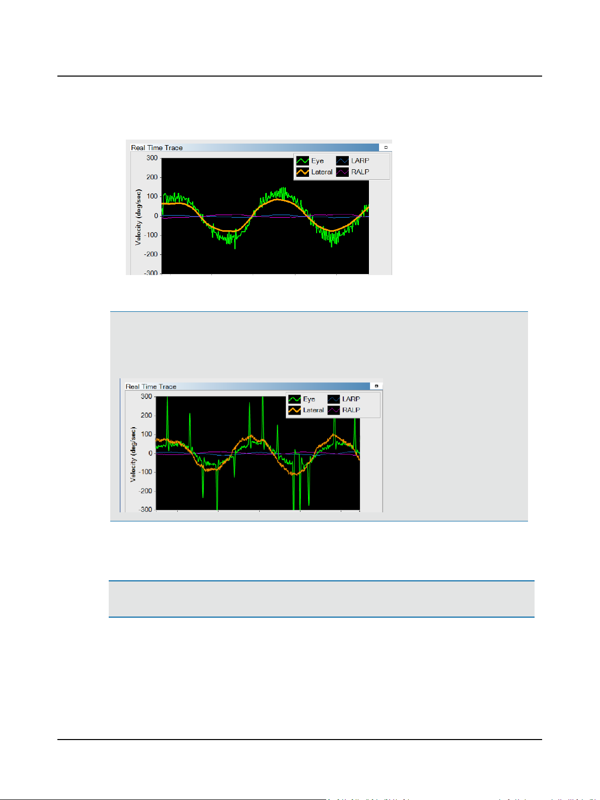
1. Ask the patient to stare at the fixation dot and move the head side to side through a small angle (about 10 degrees).
2. Check that the eye and head velocities match.
Good calibration- Eye and head velocities match
Poor calibration - Eye velocity is too low
Otometrics - ICS Impulse USB
15
Page 16
User Guide
Poor calibration - Eye velocity is too high
3. If the eye and head velocities do not match, you need to recalibrate or review the patient’s history.
Note• If the patient has to make catch-up saccades during low frequency head rotations, this can indicate
either vestibular loss, or cerebellar dysfunction, or both. When test results include catch-up saccades during
low frequency head rotations, it is recommended that the Impulse test results be interpreted with caution.
Data NOT within normal limits could be related to a peripheral and/or central disorder.
4. Once the calibration has been checked and you are satisfied with the result, click Accept.
The Collection window opens and the software is ready to begin collecting head impulse data.
Caution• Once calibration has been performed, it is recommended not to reposition the goggles on the patient’s
head.
16 Otometrics - ICS Impulse USB
Page 17
7 Adding remarks/adding video recording
Remarks regarding the test can be entered before, during, and after testing. To add or modify remarks, click the Remarks
window tab. For information about the editing tools, refer to the Reference Manual.
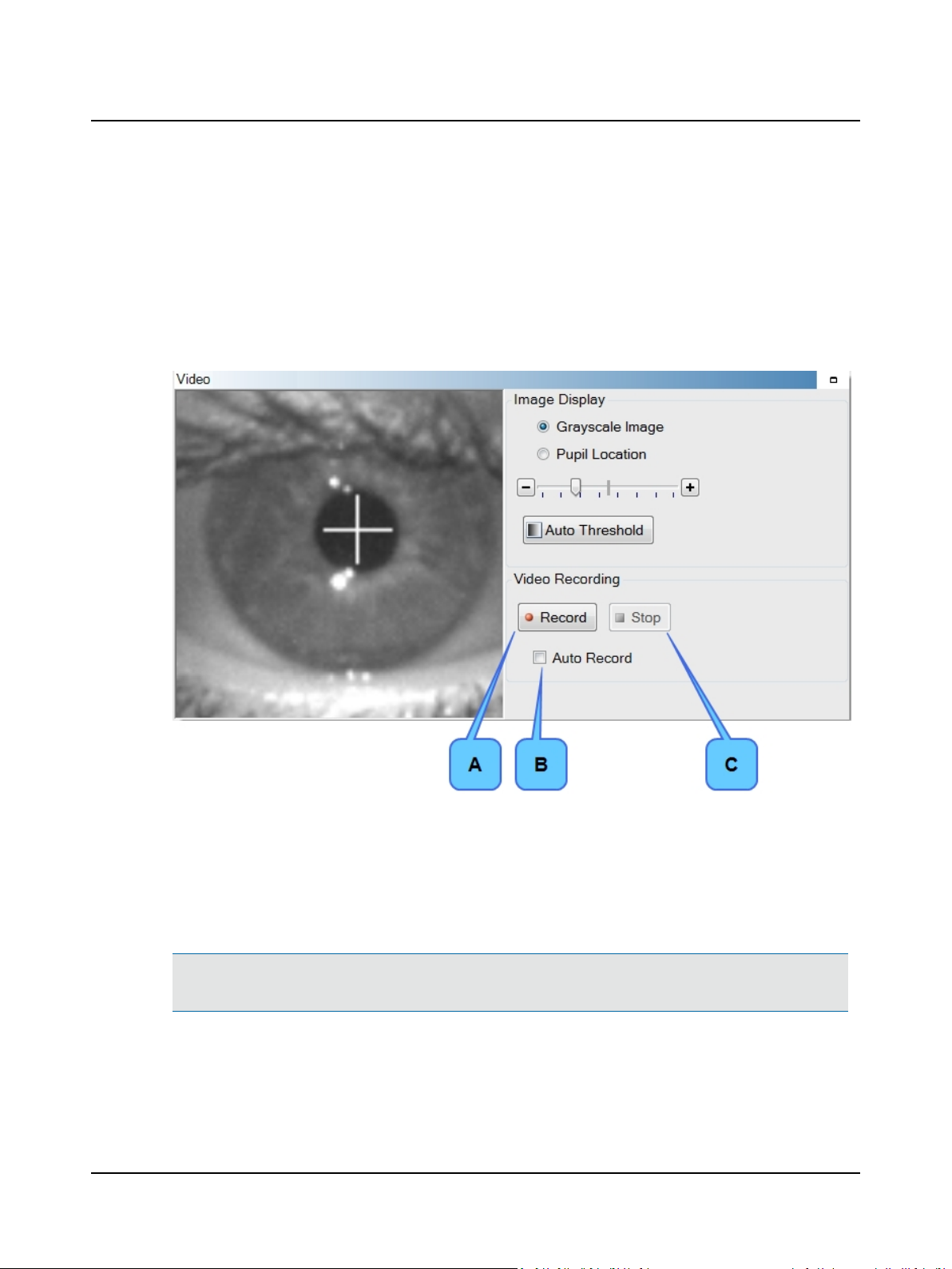
The Video window displays the image of the eye.
To start the video recording at the same time as data collection starts, select the check box AutoRecord (B). To control
the recording manually, click Record (A) to start the recording and Stop (C) to stop the recording.
User Guide
8 Collecting Head Impulse data
For information about setting variousHead Impulse options, refer to the Reference Manual.
Note• The temporary patient is available to allow testing to start without entering any patient data. Refer to Patient
data entry/lists ► 5 to create a new patient or open an existing patient.
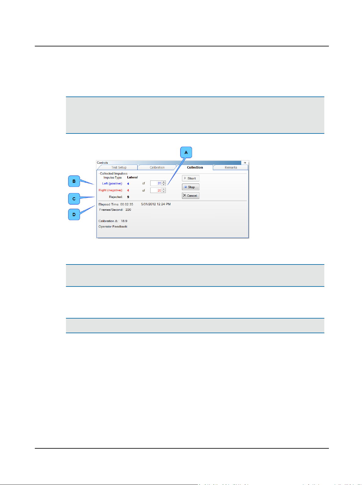
1. The Impulses settings (A) define how many valid left and right impulses are required before the test stops auto-
matically. (Impulses will be rejected if the head impulse is not performed properly or if the frame rate drops below
219 frames/second.)
To change the number of suggested minimum head impulses for the current testing session, click the up or down
Otometrics - ICS Impulse USB
17
Page 18
User Guide
arrows or type in the number directly. Twenty (20) is the recommended minimum number of head impulses for both
leftwardand rightward impulses.
Note• Impulse settings can be any number up to 999. For information about setting the default numbers, refer to the
Reference Manual.
During testing, valid impulses display for both left and right impulses (B). The left and right impulses that are not
valid (those with velocities outside a pre-determined acceptable range) are combined into the rejected count (C).
2. A disabled (grayed out) Start button indicates the system is ready for head impulse data collection. Otherwise you
must click Start to begin head impulse data collection.
Caution• Touching the goggles or the goggle strap while moving the patient’s head can result in moving the camera
which produces artifacts in the collection data.
3. Standing behind the patient, place your hands on the top of the patient’s head well away from the goggles and the
goggle strap.
Note• You can find more information in the ICS Impulse training video or at www.icsimpulse.com.
4. Ask the patient to stare at the fixation dot and move the patients head as described in the Reference Manual. It is
important to have reviewed the ICS Impulse Training Video.
5. The system automatically stops when the minimum numbers for left and right impulses have been reached. To manually stop the test, click Stop (data is saved if at least one good impulse has been collected) or Cancel (data collected is
NOT saved).
The data is automatically analyzed and displayed in the 2D Analysis window. The elapsed time (D) displays along with test
date and test time.
18 Otometrics - ICS Impulse USB
Page 19
9 Monitoring eye and head movement
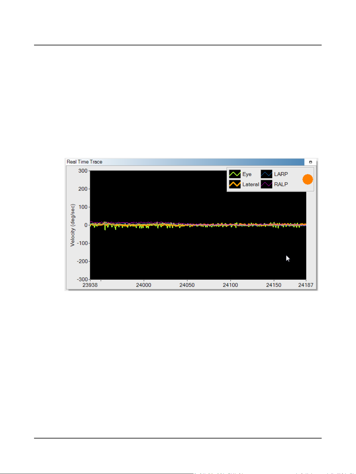
While performing the head impulse test, both the Real Time Trace window and the Impulse window display head and
eye traces to assist you in understanding the quality of data being collected.
Real Time Trace window
This window allows you to monitor both head and eye movement while performing the head impulse test. The type of
impulse selected (Lateral, LARP, or RALP) determines which head trace is bold. The bold head trace should be the one
moving when the head impulse is delivered. The other two head traces should be fairly flat. This ensures that the canal
stimulated is the one you intended to test. During the test, the maximum sample rate is 250 samples per second.
User Guide
Operator feedback is also displayed for the current impulse:
• A green circle indicates that the head impulse was delivered adequately.
• An orange circle indicates that the head impulse was not properly delivered. A message displays in the collection window alerting you to one of these errors: the impulse was too slow, there was too much overshoot in the impulse, or
wrong planes were stimulated when performing the LARP or RALP test.
If you prefer not to display the operator feedback during collection, refer to the Reference Manual.
Impulse window
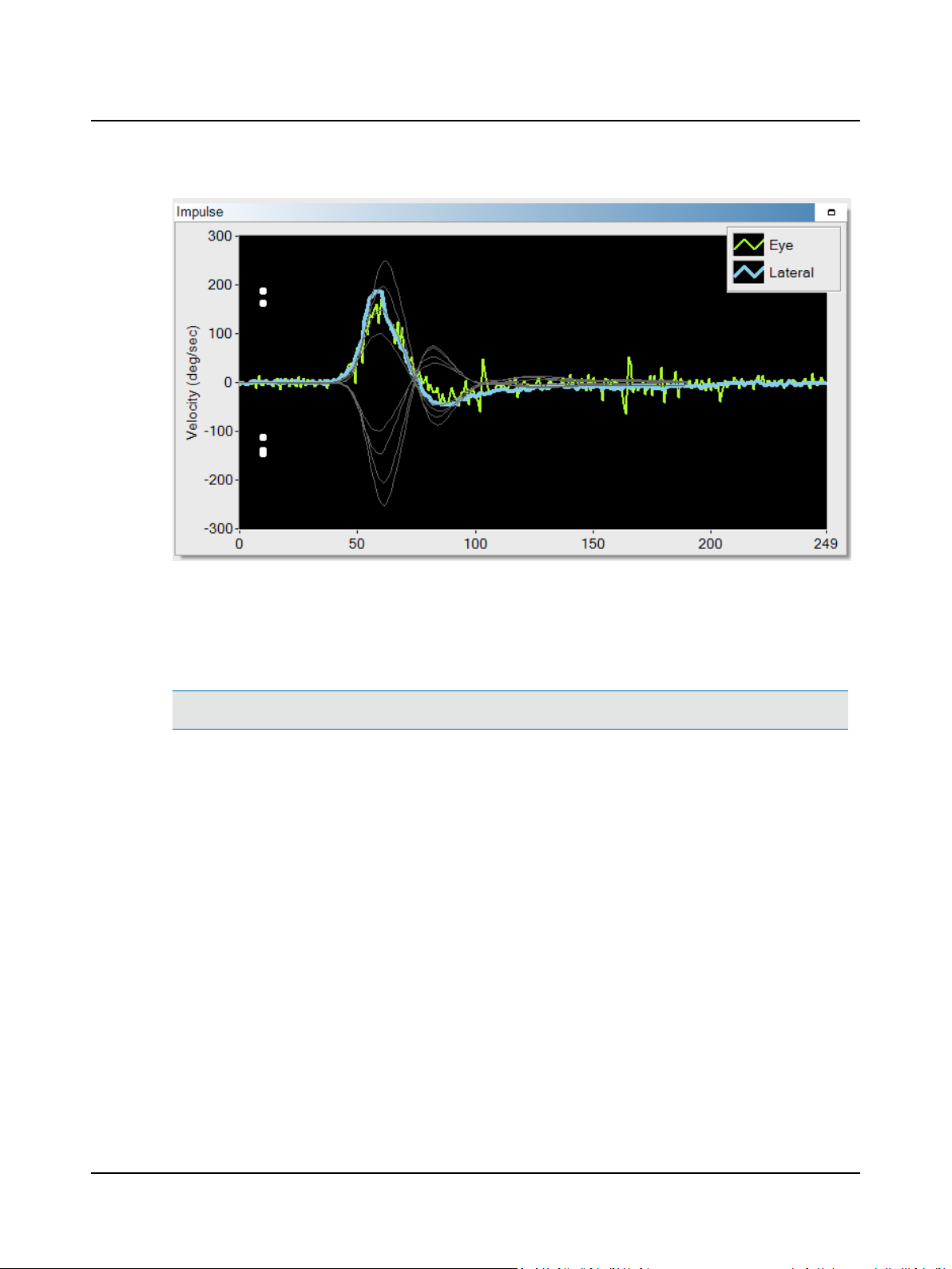
In this window, the gray training lines represent the shape of good head impulses at a variety of velocities: 100, 150, 200,
and 250. The shape of the training curves changes based on the type of impulse selected (Lateral, LARP, RALP). The head
trace displayed in orange and with negative velocities represents movement to the right. The head trace displayed in blue
and with positive velocities represents movement to the left.
The actual head and eye traces are superimposed on top of the gray training lines. The eye trace is represented in green.
White dots display along the Y axis to indicate the velocities of impulses collected.
Otometrics - ICS Impulse USB
19
Page 20
User Guide
The collection algorithm analyzes the data in real-time as it is being collected. If the head impulse meets the algorithm criteria, an accepted head impulse will be counted in the collection window. A head impulse that matches the training curve
is typically counted as an accepted (valid) head impulse.
Comparing the actual head traces (in this example shown in blue) against the training lines helps ensure that the tester performs quality head impulses and that only good data is included in the analysis.
Note• You can find more information in the ICS Impulse training video or at www.icsimpulse.com.
10 Analyzing data for a single test
Analysisof the test results can be viewed in the 2D, Hex Plot, or 3D Analysis window group.
For information about switching between viewing modes (normal mode or enlarged mode), refer to the Reference
Manual.
Gain window
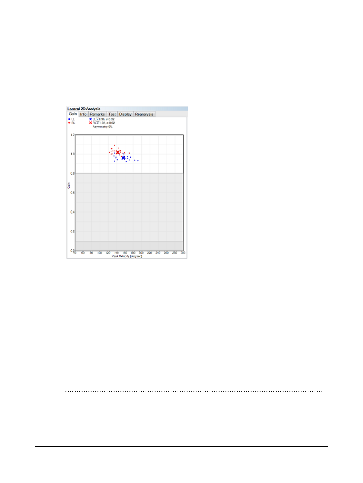
Gain is the ratio of the eye movement velocity to the head movement velocity. Individual gains and the mean gain are displayed. The Gain window displays gain values along the Y axis and corresponding peak velocities along the X axis. (The
peak velocity is the maximum velocity for each of the 175 samples representing that particular head impulse test). The
gain graph will auto scale above 1.2 if there are individual gains between 1.2 and 3.
High gain values could be the result of one of these issues or a combination of them:
1. Slippage of the goggles. Make sure the strap is very snug, the cable from the goggles is clipped to the patient’s right
shoulder or collar with some slack, and there are not gaps between the foam cushion and the patient’s face. For pictures showing good and poor goggles placement, refer to Place goggles on patient ► 9.
20 Otometrics - ICS Impulse USB
Page 21
User Guide
2. Patient is too close to the fixation dot. If the patient is closer than 1 meter, you will see increased VOR gains due to
convergence of the eyes. Never stand in front of the patient and have them fixate on your nose when using ICS
Impulse. This method of testing will result in higher VOR gains.
3. If you have ruled out 1 and 2, it could be that the patient has Meniere’s Disease.
(1)
To view only left or right gains, click the Display tab and click the Left or Right check box. To view both left and right
gains, select both check boxes. At the top of the graph a legend identifies the colors used for left and right values.
Data in the white zone is within normal limits. Data in the light gray area indicates unilateral loss. Data in the dark gray area
indicates bilateral loss. (Boundaries defined according to normative data research.
(1)
Manzari et al. Rapid fluctuations in dynamic semicircular canal function in early Meniere’s disease. Eur Arch
(2)
)
Otorhinolaryngol 14 Dec 2010.
(2)
MacDougall HG, Weber KP, McGarvie LA, Halmagyi GM, Curthoys IS (2009) The video head impulse test: Diagnostic
accuracy in peripheral vestibulopathy. Neurology 73 (14): 1134-1141.
Otometrics - ICS Impulse USB
21
Page 22
( )
xAsymmetry % = 1 − 100
lower gain
higher gain
User Guide
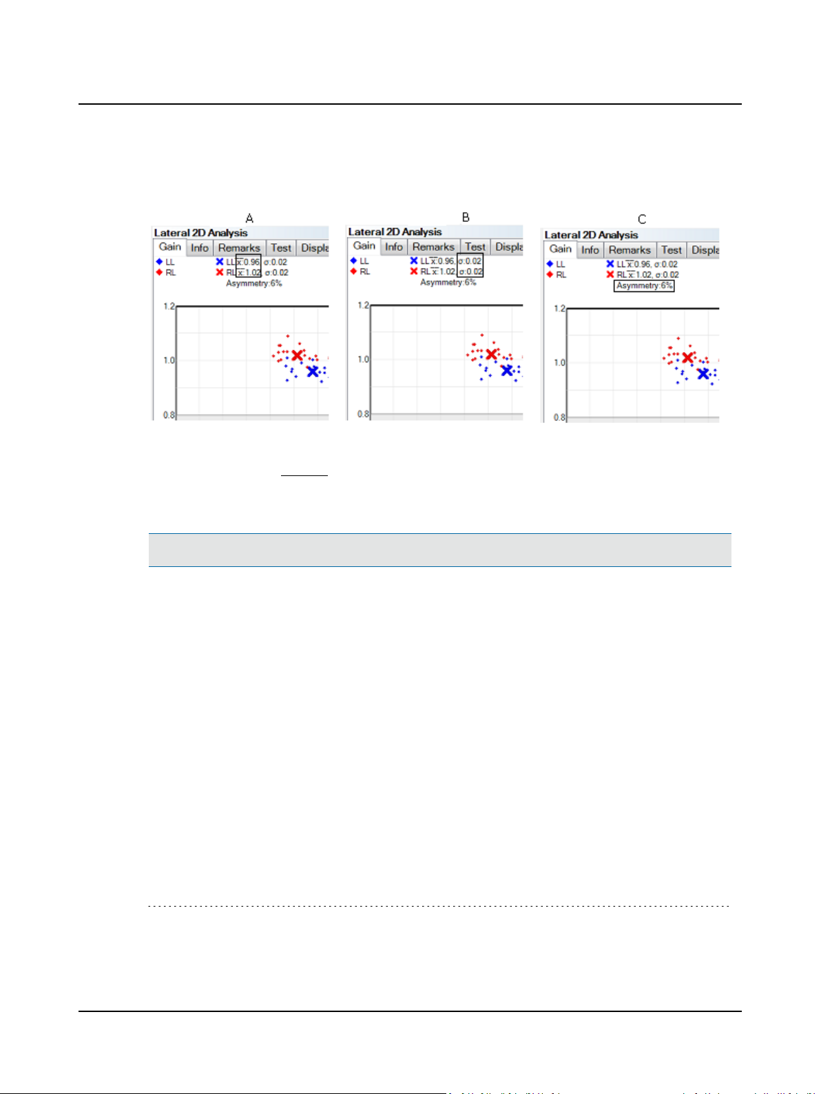
In the gain graph, the right and left means are indicated by an X. Displayed above the graph are the values for the right
and left means (A), the right and left standard deviations (B), and the asymmetry (C).
The method for calculating relative right-left vestibulo-ocular reflex asymmetry (the Asymmetry value) is as follows.
Refer to the Reference Manual.
Note• To change the boundaries for normative data, refer to the Reference Manual.
(1)
(1)
Newman-Toker DE, Saber-Tehrani AS, Mantokoudis G, Pula JH, Guede CI, Kerber KA, Blitz A, Ying SH, Hsieh YH, Rothman
RE, Hanley DF, Zee DS, Kattah JC. Quantitative video-oculography to help diagnose stroke in acute vertigo and dizziness:
toward an ECG for the eyes . Stroke.2013;STROKEAHA.111.000033.
22 Otometrics - ICS Impulse USB
Page 23
User Guide
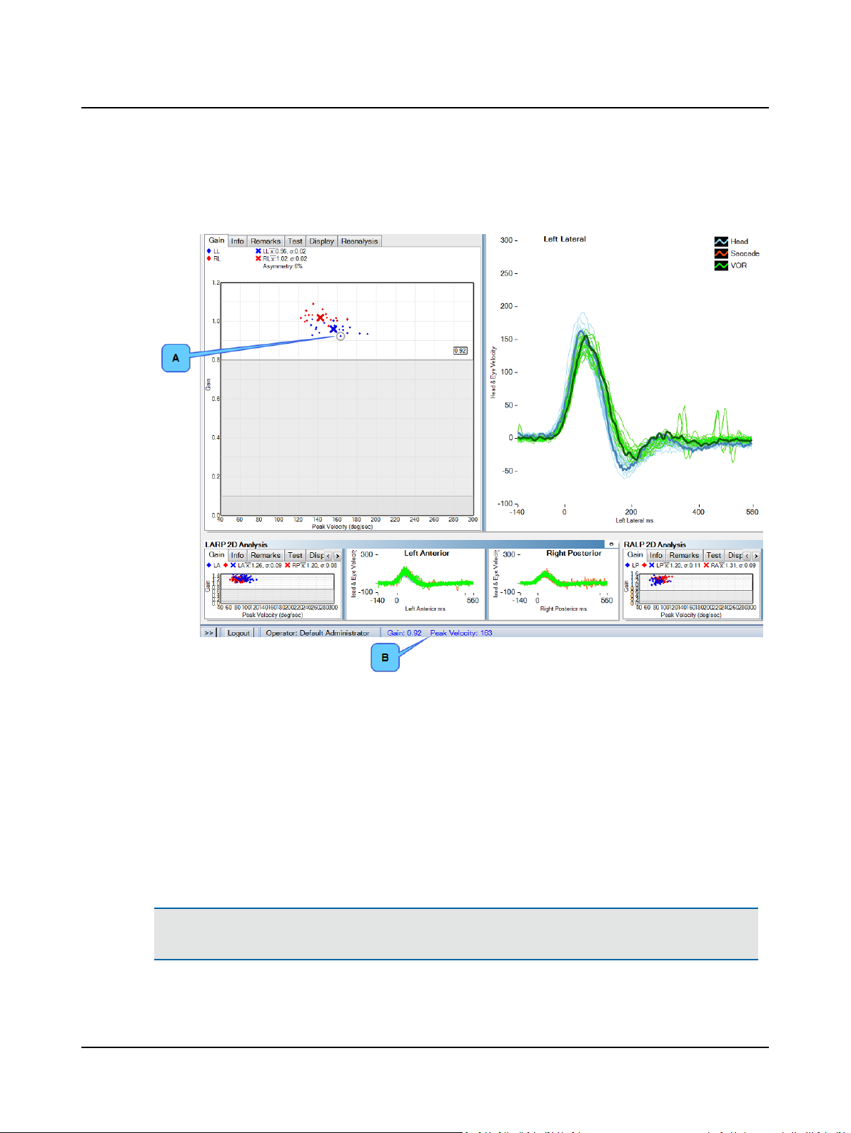
To see the gain and peak velocity values for a data point, move the cursor over the point or highlight an individual 2D
trace. The gain value displays in the window next to the point (A). Both gain and peak velocity values display in the
status bar (B).
Double-click the mouse to delete the point. Click the Reanalysis tab and then Restore Deleted Data to restore all original data points.
Info window
For an explanation of the information in the Info window, refer to the Reference Manual.
Remarkswindow
Remarks regarding the test can be entered before, during, and after testing. To add or modify remarks, click the Remarks
window tab. For information about the editing tools, refer to the Reference Manual.
Test window
For information about the Test window, including how to select a test, refer to the Reference Manual.
Caution• If you choose to delete a selected test and click Yes at the prompt, the test data is permanently deleted.
There is no possibility to retrieve the test.
Otometrics - ICS Impulse USB
23
Page 24
User Guide
Displaywindow
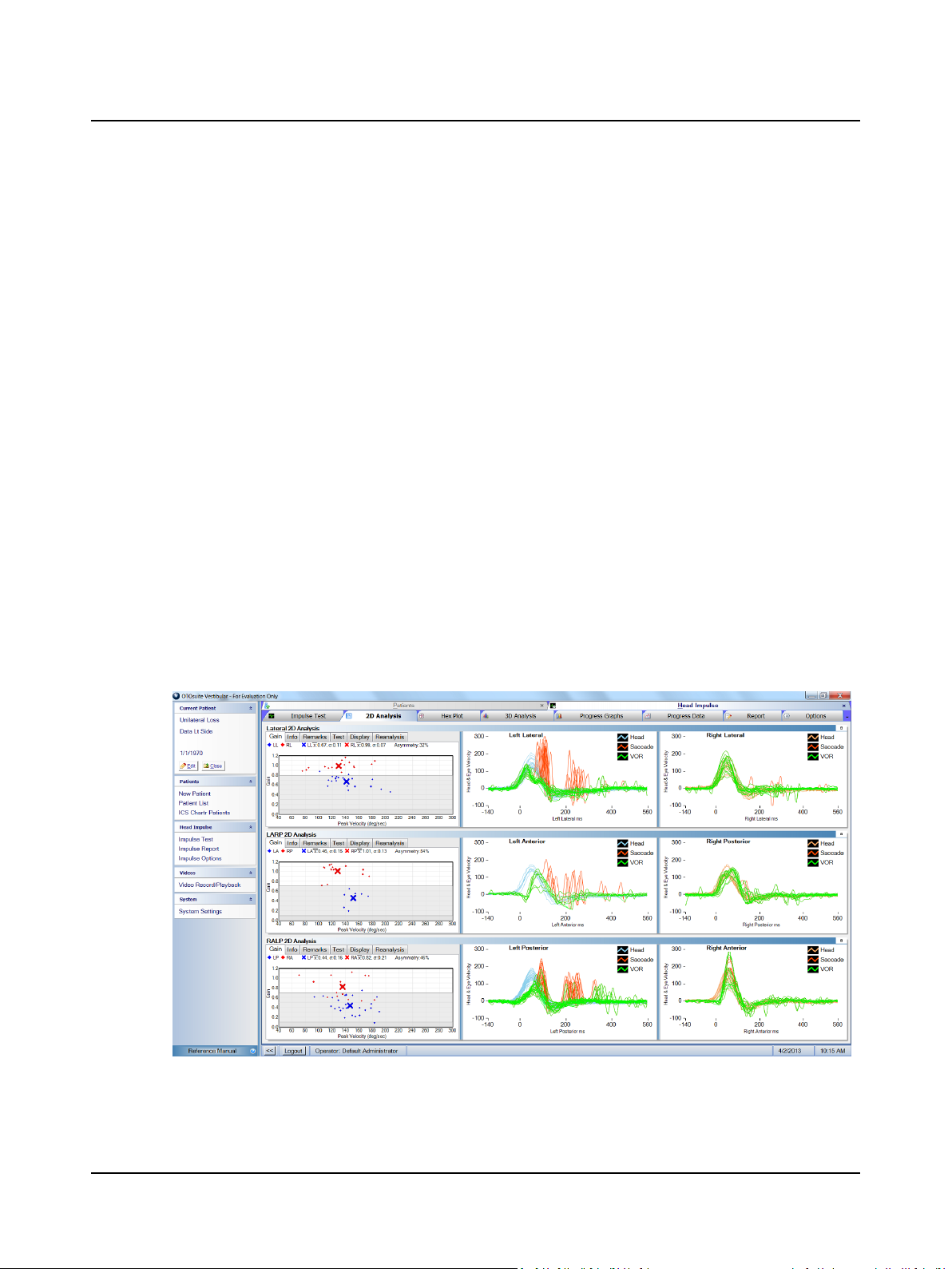
To change the Gain graph display, click the Left and/or Right check boxes to select/deselect what displays: both gains, left
gains only, or right gains only.
To modify the 2D graphs display, click the Head Velocity and/or Eye Velocity check boxes to select/deselect what dis-
plays: both velocities, head velocity only, or eye velocity only.
Reanalysiswindow
For an explanation of the settings provided in the Reanalysis window, refer to the Reference Manual.
10.1 2D Analysis
Default colors for data shown in the graphs allow those who are color blind to easily distinguish the different colors. The
default layout of the graphs places the
• left head and eye velocity data on the left
• right head and eye velocity data on the right
You can change the colors used for each type of data and switch the layout (left data on the left side and right data on the
right side or right data on the left side and left data on the right side) in the Head Impulse Options window. Refer to the
Reference Manual.
To view only the head or eye velocity, click the Display tab and click the Head Velocity or Eye Velocity check box. To
view both head and eye velocities, select both check boxes.
Head data is shown in blue for left and orange for right. Eye data shown in green identifies eye movement during and after
the head impulse (VOR). Eye data shown in red identifies saccadic eye movement (in other words, the catch-up saccades).
Data is shown with velocity plotted on the Y axis and impulse milliseconds or samples along the X axis. For data that was
converted from an earlier version of software, the X axis will display in samples if the average frame rate was below 219.
24 Otometrics - ICS Impulse USB
Page 25
User Guide
To see the gain and peak velocity values for a data point and the corresponding head and eye velocity traces, move the
cursor over the point. To scroll through the individual traces, first click in the window of interest then use the up/down
arrow keys or the scroll wheel on the mouse. Use the Delete key to delete a selected impulse.
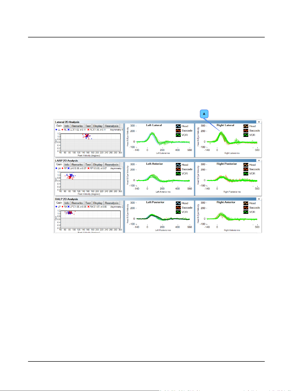
Within Normal Limits
In this example of head impulse data, both sides are within normal limits. Looking at the Gain graph the data points are all
within the normal range (in the white area). The head data shows very well performed head impulses and the eye data
shows a vestibular ocular reflex (A) that mirrors the head velocities. There may be a few catch-up saccades.
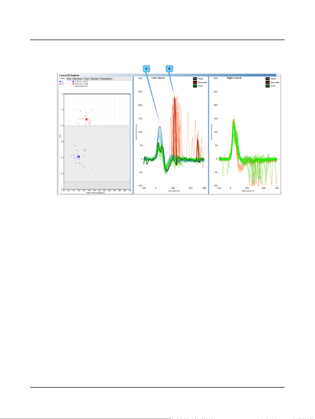
Overt saccades
This is an example of head impulse data that exhibits an abnormal vestibular ocular reflex on the left side indicated by the
gain response and the catch-up saccades. Looking at the Gain graph the data points are all within the gray range indicating a
unilateral loss. The head data shows very well performed head impulses and the eye data shows an inadequate vestibular
ocular reflex (A) that does not mirror the head velocities. There are overt catch-up saccades present (B). Catch-up saccades
are easier to visualize in the 3D analysis.
Otometrics - ICS Impulse USB
25
Page 26
User Guide
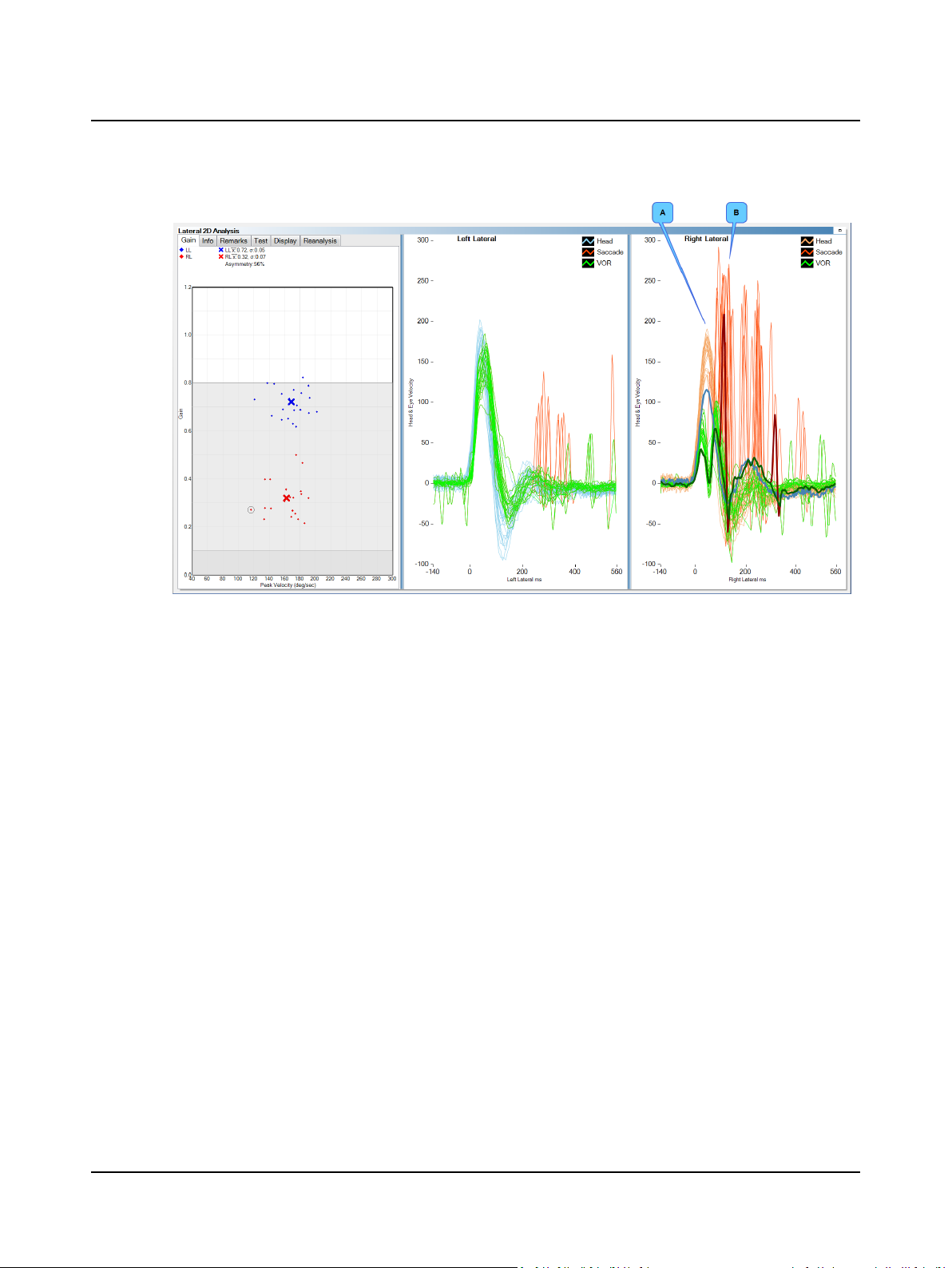
Covert Saccades
This is an example of head impulse data that exhibits an abnormal vestibular ocular reflex on the right side indicated by
the gain response and the catch-up saccades. Looking at the Gain graph the data points are all within the gray range indicating unilateral loss. Note the asymmetry of 56%. The right (abnormal) side is affecting the left (normal) side. The head data
shows well performed head impulses and the eye data shows an inadequate vestibular ocular reflex (A) that does not mirror the head velocities. There are covert catch-up saccades present (B). Catch-up saccades are easier to visualize in the 3D
analysis.
26 Otometrics - ICS Impulse USB
Page 27
User Guide
10.2 Hex Plot
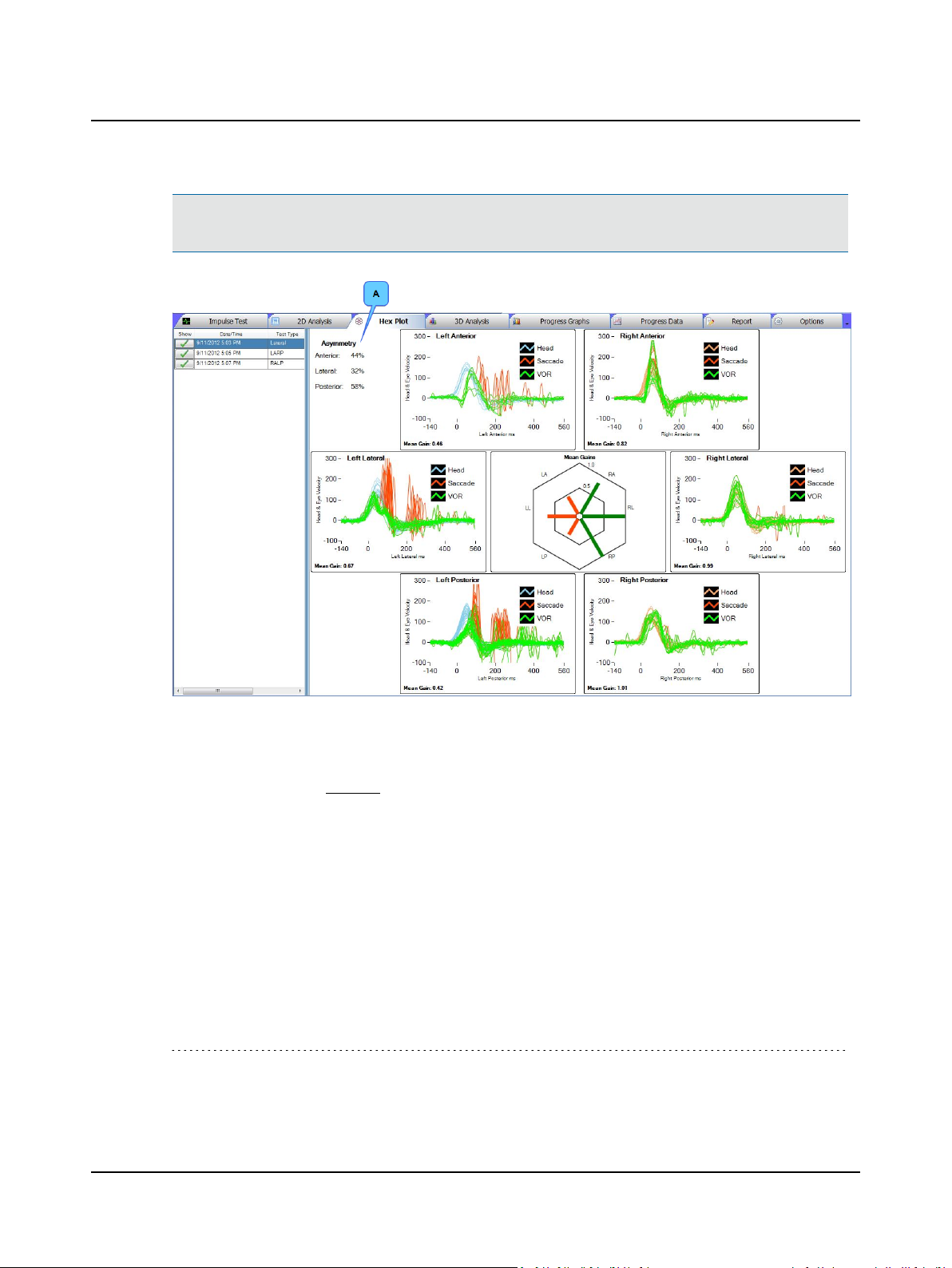
The Hex Plot window provides an overview of the mean gains as well as the 2D analysis graphs for all selected tests. The
tests initially selected are the same as the tests selected in the 2D and 3D Analysis windows.
Mean gains are represented by bars that vary in length according to the mean gain value. The bars are displayed inside a
hexagon. Each side of the hexagon is labeled with a two-letter abbreviation that refers to one of the six semicircular canals:
• LA (left anterior) • RA (right anterior)
• LL (left lateral) • RL (right lateral)
• LP (left posterior) • RP (right posterior)
The outer hexagon represents a mean gain of 1.0. The inner hexagon represent a mean gain of 0.5.
The gain bars are colored according to normative cutoff settings made in the Head Impulse Options window. Refer to the
Reference Manual.
Default colors for data shown in the graphs allow those who are color blind to easily distinguish the different colors. The
default layout of the graphs places the
• left head and eye velocity data on the left
• right head and eye velocity data on the right
You can change the colors used for each type of data and switch the layout (left data on the left side and right data on the
right side or right data on the left side and left data on the right side) in the Head Impulse Options window. Refer to the
Reference Manual.
To remove a test(s), click the button next to the test name in the Show column. To add a test(s), click the button next to
the test name in the Show column. Only one test for each test type may be selected to display on the hex plot.
Otometrics - ICS Impulse USB
27
Page 28
( )
xAsymmetry % = 1 − 100
lower gain
higher gain
User Guide
Note• The test selections revert back to the test selections in the 2D and 3D Analysis windows when the Hex Plot win-
dow is no longer displayed.
(A) The method for calculating relative right-left vestibulo-ocular reflex asymmetry (the Asymmetry value) is as fol-
Refer to the Reference Manual.
lows.
(1)
10.3 3D Analysis
Default colors for data shown in the graphs allow those who are color blind to easily distinguish the different colors. The
default layout of the graphs places the
• left head and eye velocity data on the left
• right head and eye velocity data on the right
(1)
Newman-Toker DE, Saber-Tehrani AS, Mantokoudis G, Pula JH, Guede CI, Kerber KA, Blitz A, Ying SH, Hsieh YH, Rothman
RE, Hanley DF, Zee DS, Kattah JC. Quantitative video-oculography to help diagnose stroke in acute vertigo and dizziness:
toward an ECG for the eyes . Stroke.2013;STROKEAHA.111.000033.
28 Otometrics - ICS Impulse USB
Page 29
User Guide
You can change the colors used for each type of data and switch the layout (left data on the left side and right data on the
right side or right data on the left side and left data on the right side) in the Head Impulse Options window. Refer to the
Reference Manual.
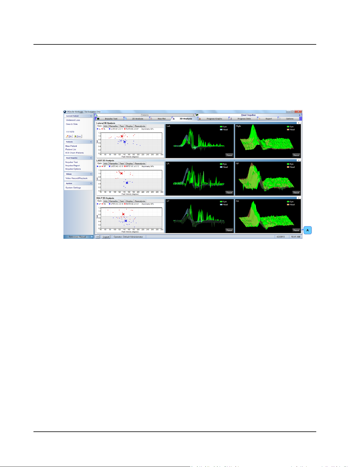
The data can be viewed from 360 degrees. To see the data from different views, hold down left-mouse button and rotate
asdesired. To return the data to the original view, click Reset (A).
Normal
In this example of head impulse data, both sides are within normal limits. Looking at the Gain graph the data points are all
within the normal range (in the white area). The head data shows very well performed head impulses and the eye data
shows a vestibular ocular reflex (A) that mirrors the head velocities. There may be a few catch-up saccades.
Otometrics - ICS Impulse USB
29
Page 30
User Guide
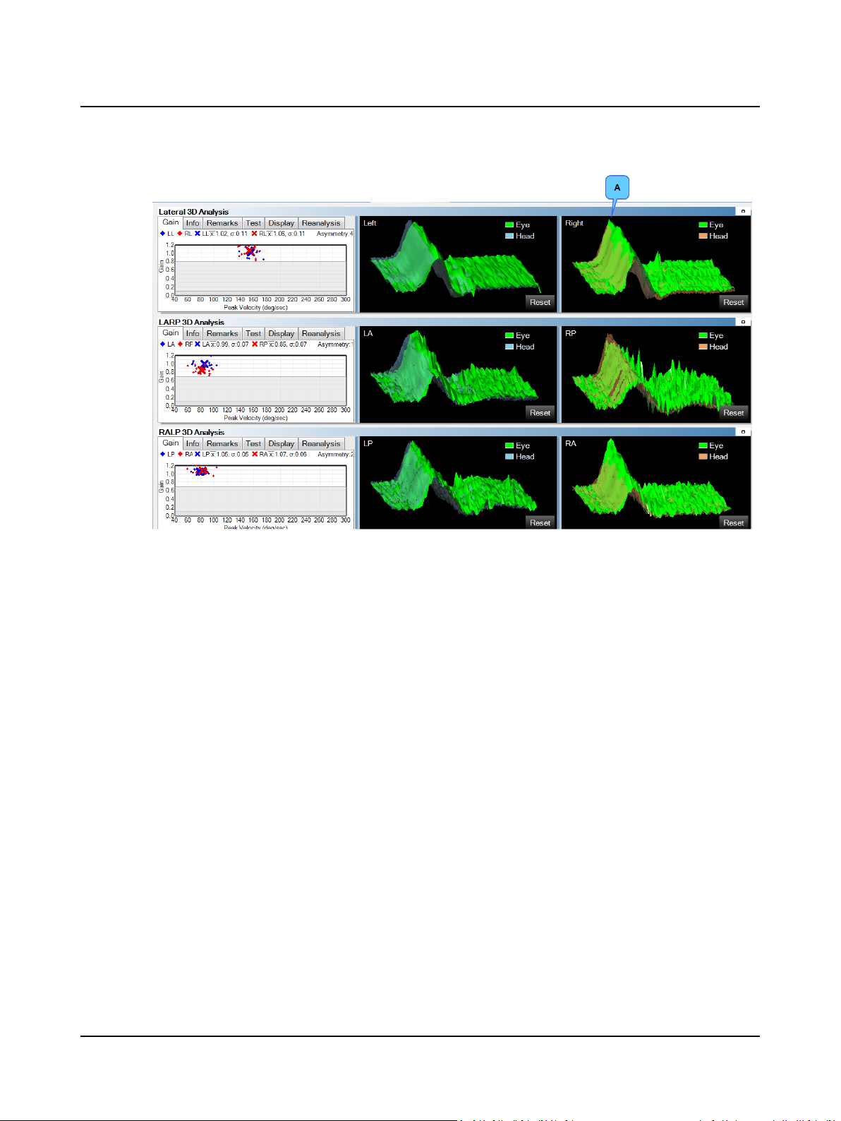
Overt saccades
This is an example of head impulse data that exhibits an abnormal vestibular ocular reflex on the left side indicated by the
gain response and the catch-up saccades. Looking at the Gain graph the data points are all within the gray range indicating a
unilateral loss. The head data shows very well performed head impulses and the eye data shows an inadequate vestibular
ocular reflex (A) that does not mirror the head velocities. There are overt catch-up saccades present (B). On the right side,
the downward spikes are due to spontaneous nystagmus.
30 Otometrics - ICS Impulse USB
Page 31
User Guide
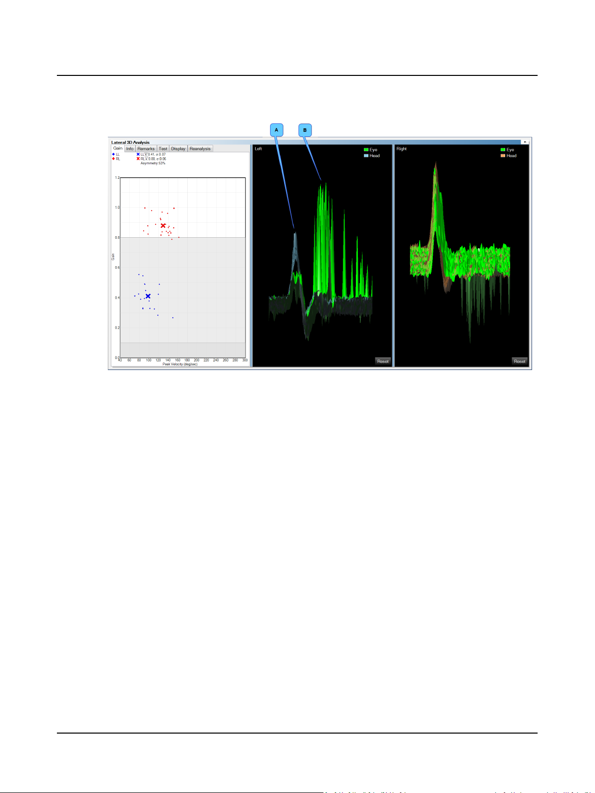
Covert saccades
This is an example of head impulse data that exhibits an abnormal vestibular ocular reflex on the right side indicated by
the gain response and the catch-up saccades. Looking at the Gain graph the data points are all within the gray range indicating unilateral loss. Note the asymmetry of 56%. The right (abnormal) side is affecting the left (normal) side. The head data
shows well performed head impulses and the eye data shows an inadequate vestibular ocular reflex (A) that does not mirror the head velocities. There are covert catch-up saccades present (B). Notice how the covert catch-up saccades are closer
to the head data whereas the overt catch-up saccades were further to the right of the head data.
Otometrics - ICS Impulse USB
31
Page 32
User Guide
11 Analyzing data for multiple-tests
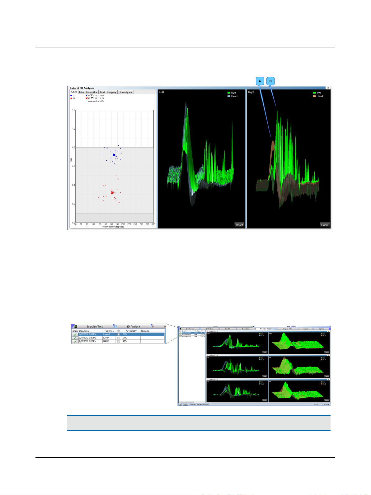
Analysisof multiple test sessions can be viewed in the Progress Graphs or Progress Data window group. This allows the
user to compare a patient's results from different test dates. By comparing test sessions, the user can see if there is
improvement or compensation has occurred.
If there are three or more tests available, the three that display initially are the first test, the most recent test, and the
test currently displayed in 2D and 3D window. To remove a test from the display, click the button next to the test name in
the Show column. To add a test(s)to the display, click the button next to each test name in the Show column.
Note• The viewing mode functions the same as the 2D and 3D Analysis. Refer to the Reference Manual.
32 Otometrics - ICS Impulse USB
Page 33
User Guide
Progress Graphs
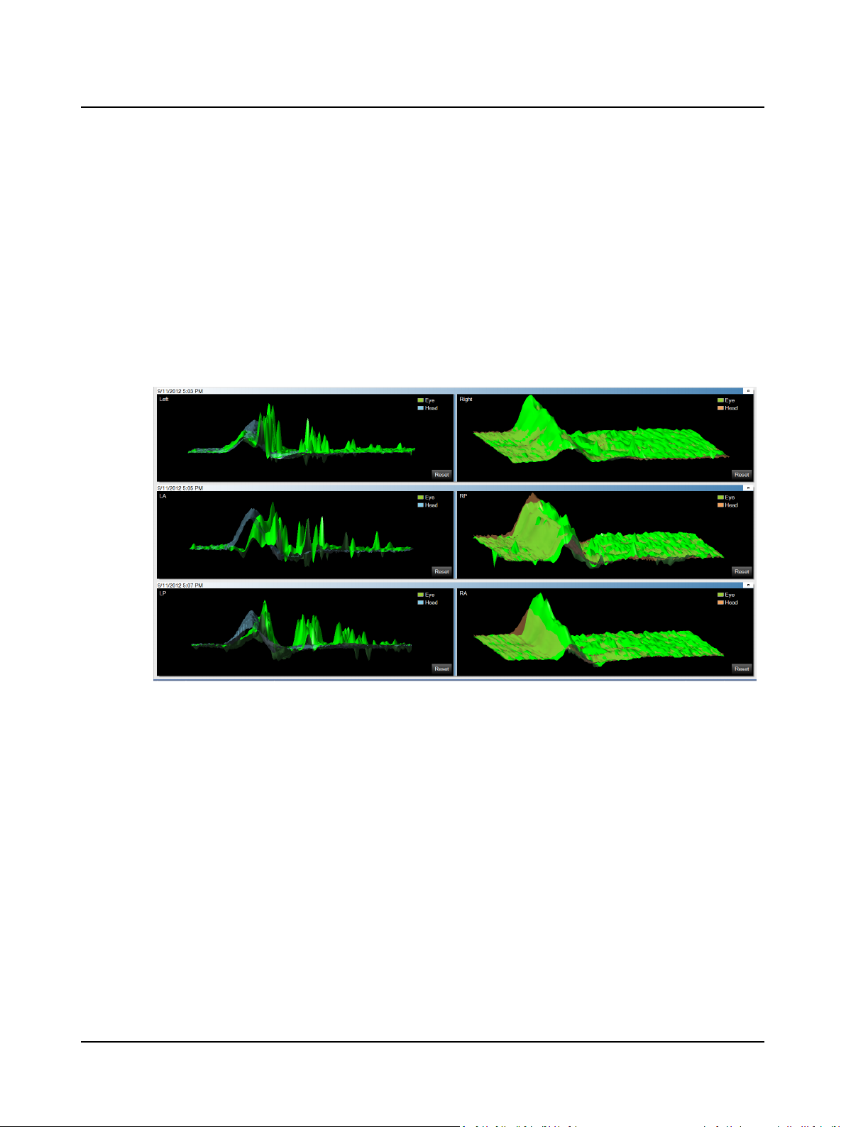
Four test sessions can be viewed together in this window. The 3D graphs display as described in 3D Analysis ► 28 except
that this window displays multiple tests. If more than 4 tests are chosen, a scroll bar will appear on the right to move the
window up and down.
Default colors for data shown in the graphs allow those who are color blind to easily distinguish the different colors. The
default layout of the graphs places the
• left head and eye velocity data on the left
• right head and eye velocity data on the right
You can change the colors used for each type of data and switch the layout (left data on the left side and right data on the
right side or right data on the left side and left data on the right side) in the Head Impulse Options window. Refer to the
Reference Manual.
Progress Data
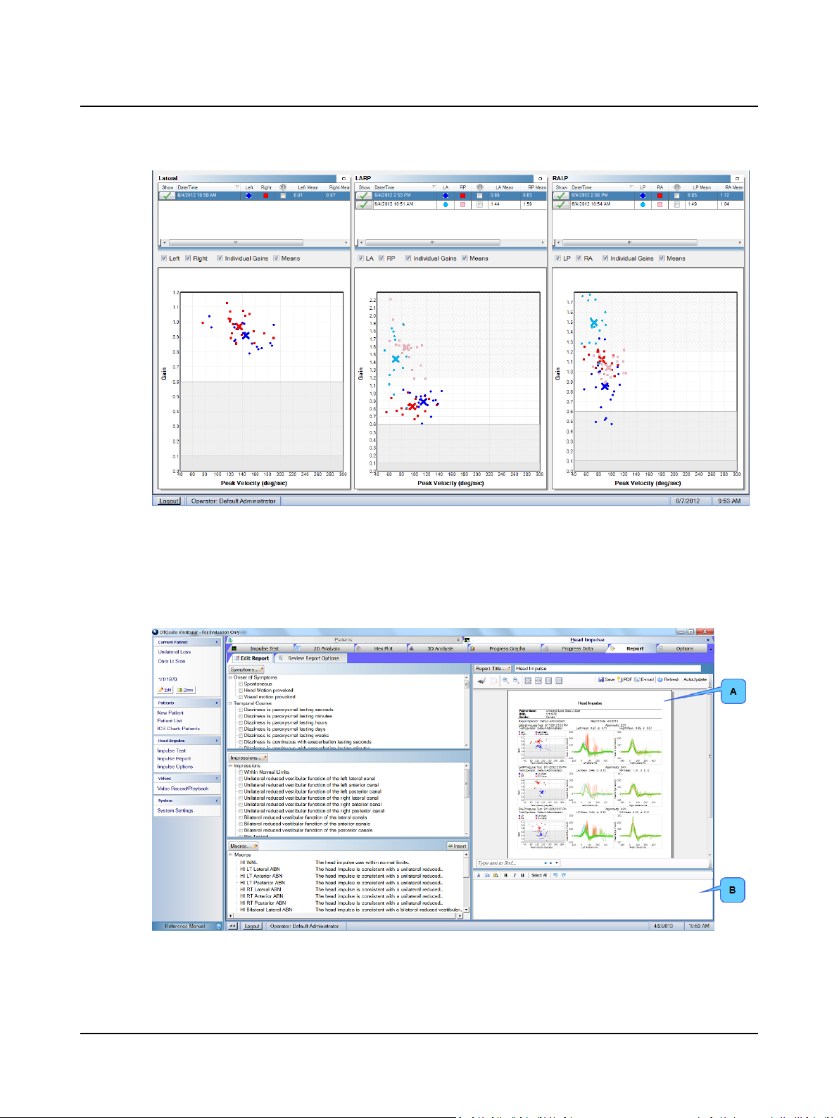
The gain graph displaysas described in Gain window ► 20 except that the legend to identify the colors used for each test
is shown in the test selection window.
Otometrics - ICS Impulse USB
33
Page 34
User Guide
12 Working with reports
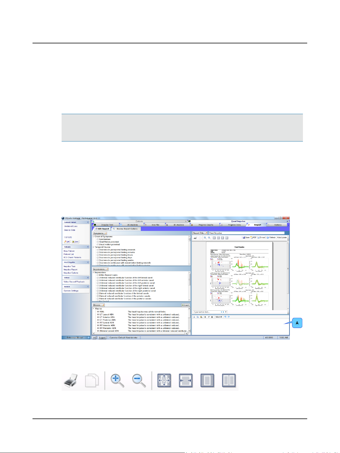
Click Report. The Report window (A) opens with the default report displayed.
Default colors for data shown in the graphs allow those who are color blind to easily distinguish the different colors. The
default layout of the graphs places the
34 Otometrics - ICS Impulse USB
Page 35
User Guide
• left head and eye velocity data on the left
• right head and eye velocity data on the right
You can change the colors used for each type of data and switch the layout (left data on the left side and right data on the
right side or right data on the left side and left data on the right side) in the Head Impulse Options window. Refer to the
Reference Manual.
Note• Settings in the Report Settings window determine which patient data and facility data are included in all
reports. Refer to the ReferenceManual. Settings in the Review Report Options window determine which report
options are included in the current report. Refer to the Reference Manual.
For information about editing the report using items from Symptoms report list or the Impressions report list refer to the
Reference Manual.
Adding findings
You can type text directly in the findings field, or you can insert text in the findings field using macros that you create with
your choice of commonly used text.
For information about entering findings by inserting a macro from the Macro report list, refer to the Reference Manual.
Text that is entered into the findingsfield (B) will appear in the Findings section of the report. For information about using
the editing tools, refer to the Reference Manual.
Report toolbar buttons
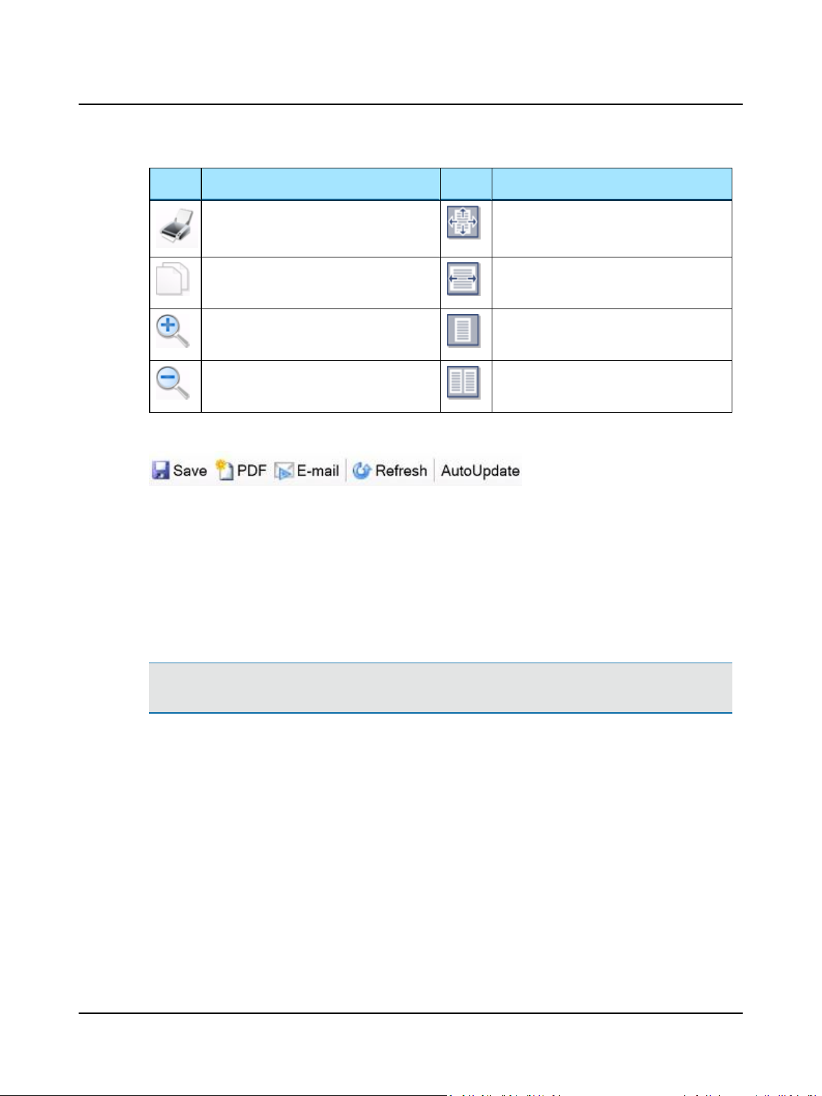
These toolbar buttons can be used to print the report, make a copy of selected text, and change how the report is displayed:
Otometrics - ICS Impulse USB
35
Page 36
User Guide
Icon
Print the report. Displaythe report page at 100% magnification.
Copy selected text to paste the text in other
documents (Notepad, a Word document, etc.).
Increase the magnification of the page. Display the entire report page in the window.
Decrease the magnification of the page. Displaytwo report pages in the window.
These toolbar buttons can be used to create the report, make a PDF file, email the report, and update the report display:
Click Save to save the default report with no changes made. Click PDF to create a PDF of the report, or E-mail to email
the report.
Icon
Displaythe entire width of the report page in
the window.
Review Report Options window
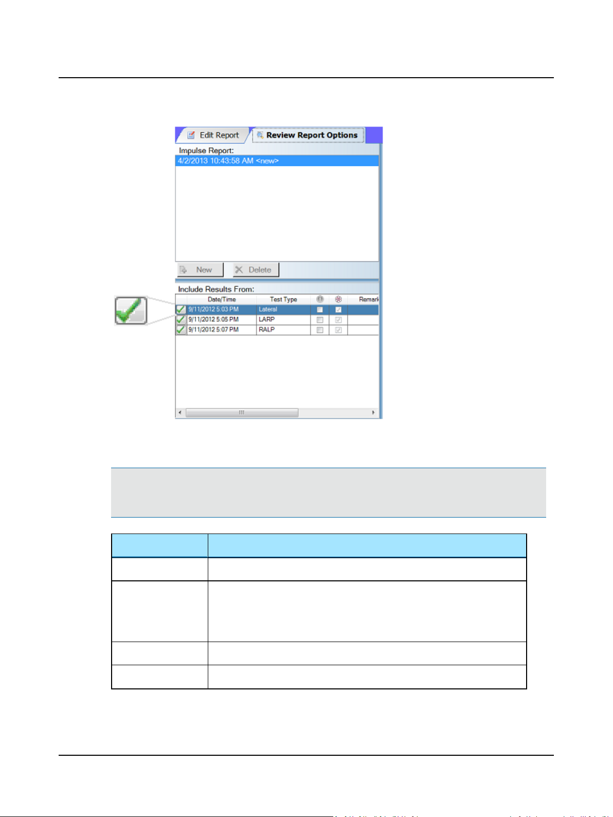
In this window you can preview all ICS Impulse reports created for the patient. (If no reports have been created for this
patient, the application creates a report based on the default settings.)
You can make a new report that combines several ICS Impulse test sessions into one report. To create a new report, click
New. To delete an existing report, click the report name and click Delete. After the report has been deleted it cannot be
recovered.
Note• If the current report is the default report without any changes made to the report, both New and Delete are
disabled unless you press Save.
To add a test to the report, click the check box at the left of the test name in the Include Results From list. Clicking the
check box again removes the test from the report.
36 Otometrics - ICS Impulse USB
Page 37
User Guide
Click the check box for each report option to be included in the report. Click Select All to include all options in the
report. Click Deselect All to not include any of the options in the report.
Note• The gain graph along with the 2D impulse graphs from one test session should fit on one page. If multiple tests
sessions are chosen, or a progress graph is included, then the report will include multiple pages. 3D graphs can not be
included in the report.
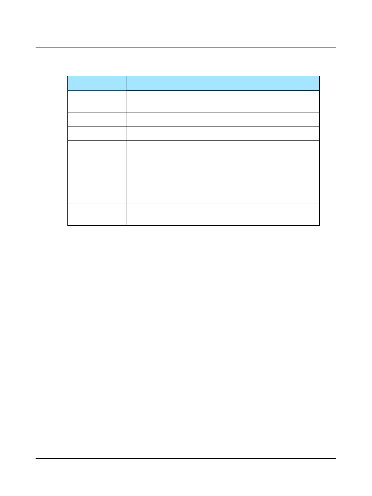
Option Includes
Progress Data
MeanGains
Gain Graph
2D Impulse graphs
gain graphs displayed in the progressdata window
mean gain symbols on the gain graph as displayed in the 2D/3D window (values display
by default)
mean gain symbols and values on the gain graphs displayed in the progress data window
gain graph displayed in the 2D/3D window
eye (saccade and VOR) and head traces displayed in the 2D window
Otometrics - ICS Impulse USB
37
Page 38
User Guide
Option Includes
Large 2D Impulse
graphs
Test Remarks
Calibration Graph
Test Info
Hex Plot
eye (saccade and VOR) and head traces displayed in the 2D window printed larger than
the selection
any test remarks in the patient file
a snapshot of the real time trace during the calibration check
the numbers of the accepted and rejected head impulses from the collection and analysis algorithms as displayed in the Info tab in the 2D/3D window, average frame rate,
and information regarding factors affecting test analysis such as
- Patient has Spontaneous Nystagmus (when Spontaneous Nystagmus was
checked in the Test Setupwindow)
- Catch-up Parameters Modified (if values were changed in the Reanalysis win-
dow)
include eye (saccade and VOR) and head traces and hex plot displayed in the
window
2D Impulse graphs
13 How to record and play back video
Record
When recording an eye video, there are 2 image size options: Full Image or Region of Interest (ROI).
Hex Plot
38 Otometrics - ICS Impulse USB
Page 39
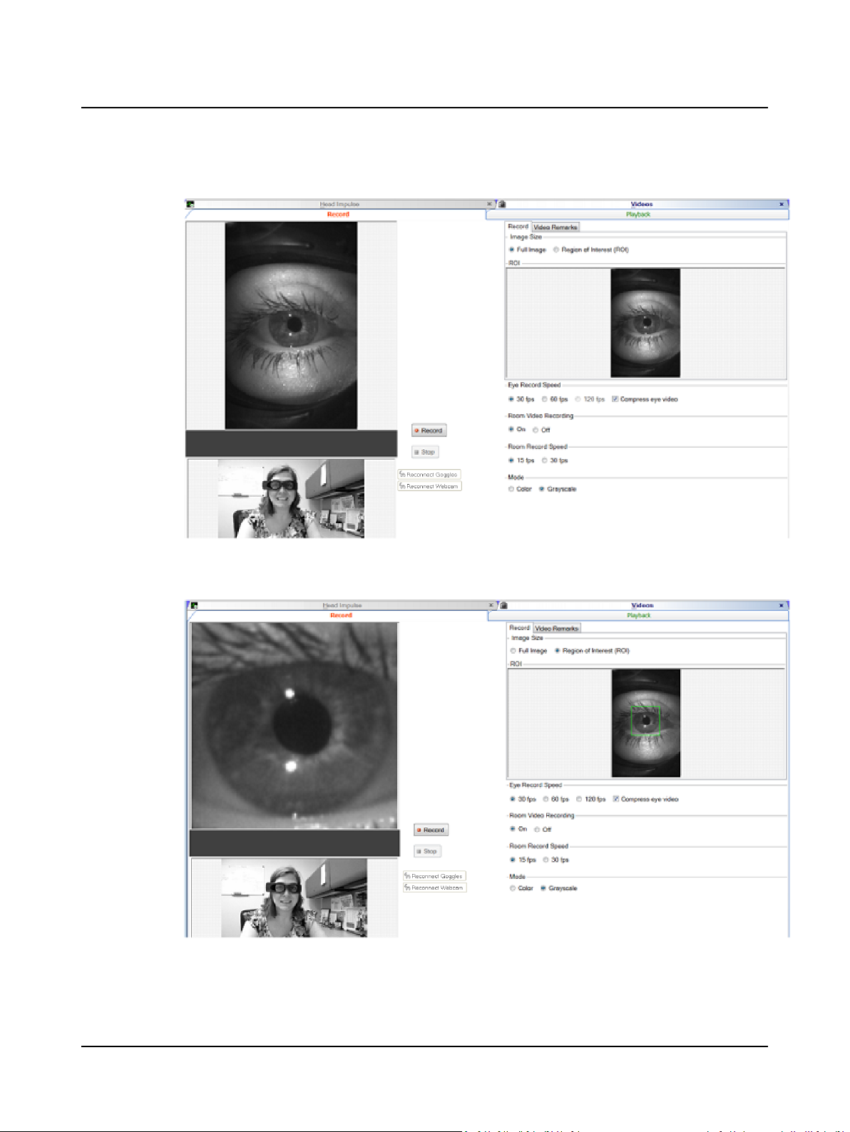
Full Image
User Guide
Region of Interest (ROI)
Otometrics - ICS Impulse USB
39
Page 40
User Guide
Note• Select the Video Remarks tab to enter remarksin the text field of the Video Remarks window. For inform-
ation about using the editing tools, refer tothe Reference Manual.
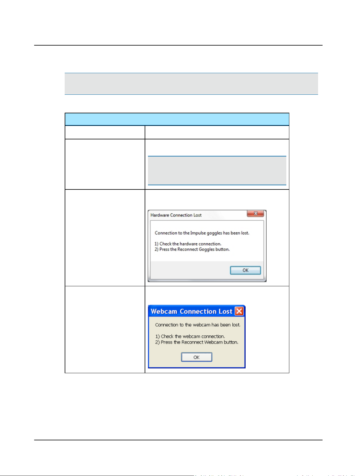
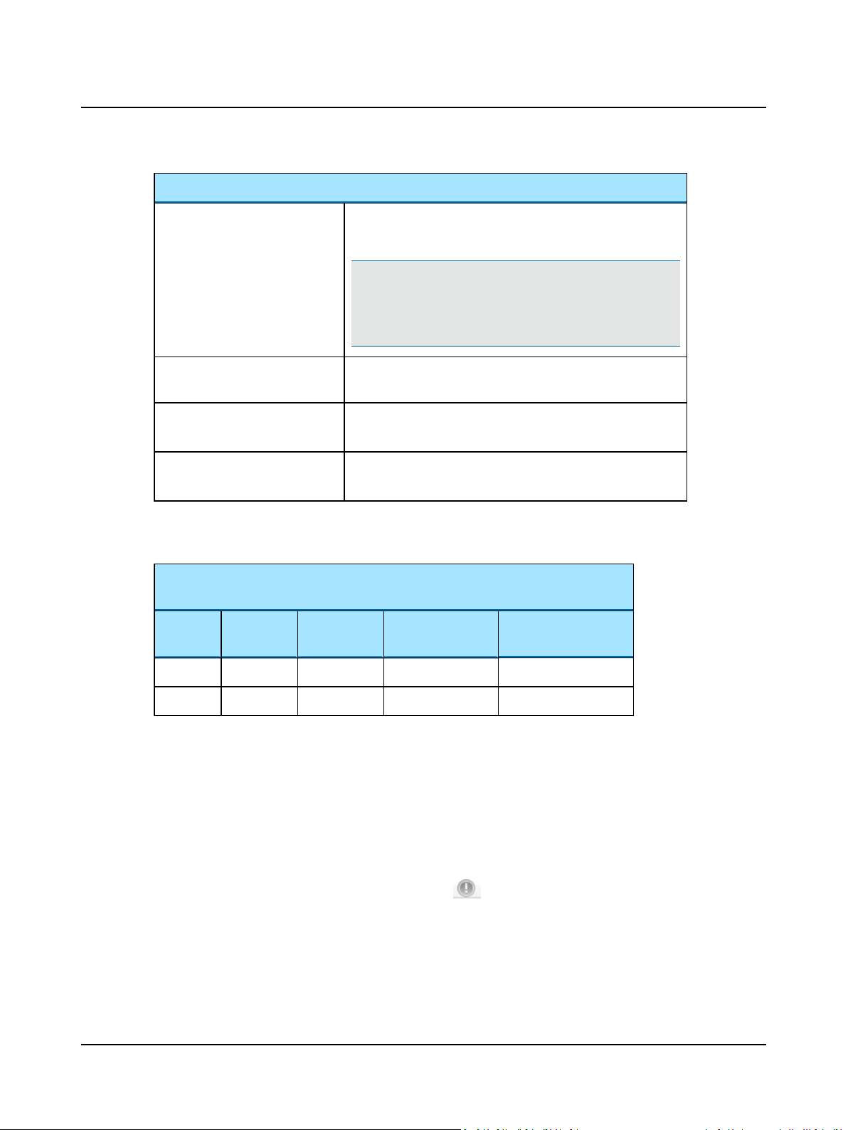
Video Record buttons and selections
Record
Stop
Reconnect Goggles
Reconnect Webcam
Start video recording
Stop video recording
Note• There is no limit to the length of the video recording;
however, the longer the video recording is the larger the file
will be on the hard drive.
Reconnect goggles (software-to-hardware connection) as instructed
by this error message:
Reconnect synchronized room video as instructed by this error
message:
40 Otometrics - ICS Impulse USB
Page 41
Video Record buttons and selections
Eye Record Speed Full Image - Options for recording: 30 or 60 frames per second
ROI - Options for recording: 30, 60, or 120 frames per second
Note• If the video is recorded at 60 or 120 frames per second
it can be played back in slow motion or at normal speed. At
normal speed some frames will be skipped. The eye video can
also be compressed.
User Guide
Room Video Recording
Room Record Speed
Mode (synchronized room video
only)
You can record eye video only or eye video with room video. If you chose to combine eye and room video, this example
shows the resulting file size for a 20-minute recording.
Eye Video Eye Video
Size
ROI 120 MB 270 MB 1.51 GB 15-20
Full Image 585 MB 270 MB 1.93 GB 15-20
Room Video
Size
Turn synchronized room video recording on and off. Room video is
always compressed.
Choose 15 or 30 frames per second. The higher the frame rate the
larger the file size.
Choose to record the video in color or grayscale. Color video creates a larger file size.
Eye Video (60 fps, compressed)
Room Video (15 fps, grayscale)
Combined Video
File Size
Time to Export Combined Video (minutes)
Playback
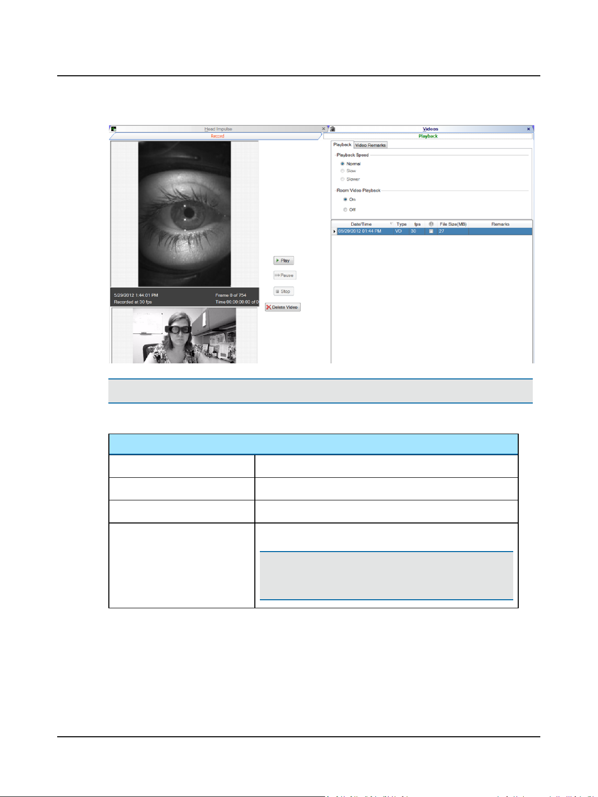
The list of videos that have been collected for the selected patient (including videos collected during head impulse testing) is displayed along with the following information about each video file:
• Date/Time - Date and time the video was collected
• Type - Indicates if the video was collected during head impulse testing (HI) or separately (VO = video only)
• Fps - Frame rate at which the video wasrecorded (frames per second)
• Unique identifier - To mark a file for a specific purpose (for example, to indicate abnormal results), click in the check
box under the column heading marked with this symbol: .
• File Size - File size of the eye video. If the synchronized room video was used during recording, the file size is a com-
bination of the eye and room video.
Otometrics - ICS Impulse USB
41
Page 42
User Guide
Note• To conserve disk storage space, it is important to delete all videos that are not important.
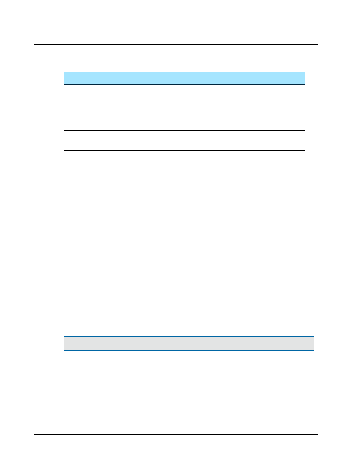
Video Playback buttons and selections
Play
Pause
Stop
Delete Video
Plays the video
Pauses the video
Stops the video
Deletes the video.
Note• After a video has been deleted it cannot be recovered. It is
recommended to delete videos that are not needed in order to save
disk drive space
42 Otometrics - ICS Impulse USB
Page 43
Video Playback buttons and selections
User Guide
Playback Speed
Room Video Playback
14 System settings
Administrator window
Only users with Add User as Administrator selected in their profile have access to this window where user data can be
created, edited, and deleted.
Also, here is where the network locations are set for shared files (videos, reports (PDF), export, and import). For more
information, refer to Changing the storage locations for videos, export, import, report PDFs ► 51 for more information.
List operations
The user data is separated into columns according to the type of information: Last name, first name, user name, etc.
Video recorded at
• 30 frames per second can only be played back at normal speed.
• 60 frames per second can be played back at normal or slow speed.
• 120 frames per second can be played back at normal, slow, or slower
speed.
Choose to play the room video recorded with the synchronized room
video. The room video is synchronized with the eye video at all speeds.
Reordering lists Click the column header, to reverse the order. For example,
Changing column width In the column heading of two adjacent columns, click the cursor
Set up a new user
Important• Set up at least one user with administrator privileges.
1. Click New.
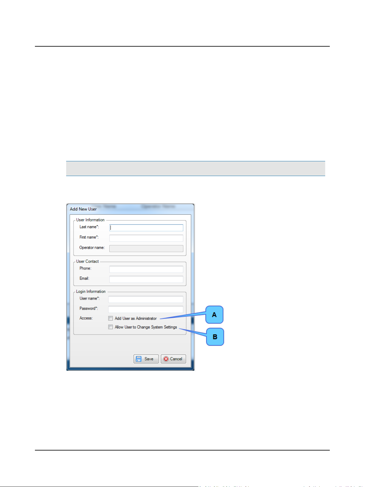
2. To give the user administrator privileges, click Add User as Administrator (A). This setting gives the user the ability to
• add, edit, or delete users,
• specifythe network locations for shared files (video, reports (PDF), import, and export),
• update application license and firmware, and
• change system settings.
Otometrics - ICS Impulse USB
Click Last Name to change the order from A-Z to Z-A.
on the line dividing two columns. The cursor changesto a
double-headed arrow. Drag the cursor to increase or decrease
the column width.
43
Page 44
User Guide
3. To give the user privileges to change the system settings, click Allow User to Change System Settings (B). This setting
gives the user access to
• Set cutoff lines for gain normative data
• Enter e-mail settings used for mailing reports
• Choose patient, facility, and operator information to include in reports
• Performdatabase operations
• Enter GDT interface settings
• Change catch-up saccade parameters and restore to default parameters
For information about these settings, refer to the Reference Manual.
Note• Both user name and password are case sensitive.
4. Enter data. Entries that cannot be left blank are marked with an asterisk (*).
5. Click Save to save the changes. Click Cancel to discard the changes.
Edit user data
1. Select the user from the list.
2. Click Edit.
3. Edit the changes making sure all required fields marked with an asterisk (*) are completed.
4. Click Save to save the changes. Click Cancel to discard the changes.
44 Otometrics - ICS Impulse USB
Page 45
Delete user
1. Select the user from the list.
2. Click Delete.
3. Click OK.
Additional system settings:
• Workstation Settings
• Facility Info
• Report Settings
• OTOsuiteVestibular Database
• GDT Interface
Refer to the Reference Manual.
15 Installation and Setup
User Guide
Important• The previous version of goggles (those with firewire and USB connections) are not compatible with
OTOsuiteVestibular versions 2.0 or later.
This section describes all steps required to complete the ICS Impulse System setup:
• Installing OTOsuiteVestibular software
• Connecting the goggles
• Installing the synchronized room video
• Importing sample report lists (not required for server-only installations)
• Importing demo data
• Customizing for your facility
• Installing Abobe Reader
• Setting up a networked database and workstation (not required for standalone installations)
15.1 Minimum computer requirements
Operating System 64-bit: Windows 8 Pro, Windows 7 Professional
32- bit: Windows 8 Pro, Windows 7 Professional, and Windows XP Professional (SP3 or
higher)
CPU Intel i5 processor
Memory 64-bit (Windows 8 or Windows 7): 6GB
32-bit (Windows 8, Windows7, or Windows XP): 4GB
Otometrics - ICS Impulse USB
45
Page 46
User Guide
Disk Space 300GB
Connectors One USB 2.0 (for the goggles) and one
USB 2.0 or USB 3.0 (for the synchronized room video)
DVD Drive DVD R/W
Monitor 1600 x 900 Screen resolution
Components Mouse, keyboard
15.2 Software Installation
Note• For information about uninstalling, reinstalling, or upgrading the OTOsuiteVestibular software, refer to the
Reference Manual.
Start installation
Note• Possible error messagesand what to do if they appear:
- Firewall messages: Please allow access.
- User Account Control (UAC) message: For Windows 7 and Windows 8 systems, a message that refers to the User
Account Control (UAC) may display. Accept this message as it does not indicate a problem.
- Microsoft Webcam or SQL Server error messages: If Microsoft has installed new Window updates, and the com-
puter has not been rebooted, an error message may appear. Please reboot your PC and restart the software installation.
1. Save any files currently open and quit all programs.
2. Insert the OTOsuite Vestibular DVD.
Note• If the computer is set up to AutoRun, the installation starts. If AutoRun is not initialized, browse the DVD to
find this icon .
3. Click setup. (You may need to close the DVD content folder.)
4. If you have Windows 7 or Windows 8, a security dialog will appear. Click Yes.
5. Installation of OTOsuiteVestibular requires certain applications (such as Windows Installer) to be installed on the computer. If an application(s) is missing, a dialog box lists the missing application(s).
- Click Install. When the application(s) has been installed, the computer will restart.
- Log in to computer. The installation continues automatically.
6. The Welcome screen appears. Click Next.
7. Select I accept the terms in the license and click Next.
8. The Anonymous Usage Statistics screen displays. Click Next.
46 Otometrics - ICS Impulse USB
Page 47
User Guide
Note• The Eqatec application is installed by default. It can be turned off in the Error Logs window of System Settings.
If connected to the Internet, Eqatec gathers computer information and unhandled exceptions. This information can
help us understand problems and resolve them in future revisions. No patient information or any information that
would identify the facility or the exact computer is collected. Again, this information is only collected if the computer
is connected to Internet.
Note• During the installation of OTOsuiteVestibular, you will see references to various other associated programs
that are being installed. These other programs include: SQL Server (OTOsuiteVestibular database), Access Database
Engine (supports the Chartr database), and Infragistics (reporting).
Choose installation type
OTOsuiteVestibular can be installed in a client/server or standalone configuration. In client/server, a single server hosts
the database for one or more client workstations where the OTOsuiteVestibular application is installed. We recommend
client/server installs to be set up using network domains. Use of workgroupsis not recommended because it will require
the same user name and password be used on each computer. In standalone a single computer hosts both the database
and the OTOsuiteVestibular applications.
Choose how OTOsuiteVestibular will be installed:
• Standalone installation
Hosts SQL database and OTOsuiteVestibular application (no additional clients)
Select Standalone and click Next. Continue at Complete the installation ► 48.
• Network installation - Server
Hosts SQL database and a limited version of the OTOsuiteVestibular application (The limited version supports patient
management (create, import, and export patients), system settings changes and database management. It does not
allow viewing tests or collecting test data.) Continue to Server/Bothinstallation ► 47.
• Network installation - Client
Hosts OTOsuiteVestibular application
Continue at Client installation ► 48.
• Network installation - Both (Client/Server)
Hosts SQL database and OTOsuiteVestibular application. Can support additional clients.
Continue to Server/Both installation ► 47.
Server/Both installation
Before startingthe installation, determine the type of installation required:
• Server only - OTOsuiteVestibular database and a limited version of OTOsuite Vestibular software for archiving/backing
up data will be installed.
• Both (Server and Client)
1. Select Server or Both and click Next.
Note• Although it is possible to change the port number (used by the SQL server), we recommended you use the one
supplied on the screen.
Otometrics - ICS Impulse USB
47
Page 48
User Guide
2. Make note of the entries for Port Number and Server ComputerName as this information will be required for all cli-
ent computers. (For computers connected to a printer, you can click Print to print out the information.)
3. If Bothwas selected, click Next and continue at Complete the installation ► 48.
4. If Server was selected, click Next and continue at Complete the installation ► 48.
Client installation
1. Select Client and click Next.
2. Enter the port number and the server computer name obtained from the server installation.
3. Click Next and continue at Complete the installation ► 48.
Complete the installation
1. Click Install. A status window appears reporting the progress of the installation.
2. For server-only installations, click Finish and continue at Importing demo data ► 50.
3. For all other installations, click Finish and continue at Connecting the goggles ► 48.
.
15.3 Connecting the goggles
Note• The current version of softwaredoes not support the previous version of the goggles where the connection to
the computer was through an interface box. The current version of goggles has a single cable that connects directly
to the computer.
1. Remove the cover from the goggle lens.
Note• Keep the cover. When the goggles are not in use, put the cover back on to prevent dust from accumulating on
the lens.
2. Connect the USB cable to the 2.0 USB connector on the computer.
3. If installing the synchronized room video, continue to Installing the synchronized room video ► 48. Otherwise, click
(OTOsuiteV icon found on the desktop)to open the application.
15.4 Installing the synchronized room video
Note • To use the synchronized room video with OTOsuiteVestibular, the software license with synchronized
room video must be purchased from Natus Medical Denmark.
48 Otometrics - ICS Impulse USB
Page 49
User Guide
Important• Start the procedure with the synchronized room video disconnected.
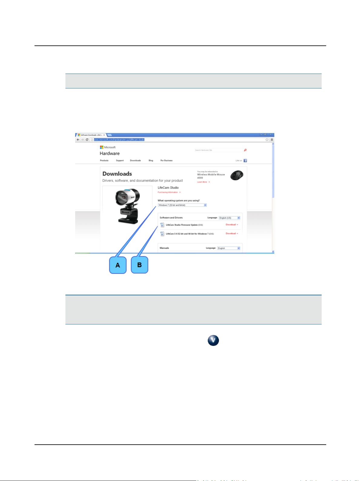
1. Go to: http://www.microsoft.com/hardware/en-us/d/lifecam-studio
2. Select the operating system (A).
3. Downloadthe LifeCam file. For example, if you choose Windows 7, download LifeCam 3.6 32-bit and 64-bit for Win-
dows 7 (B).
4. Double-click the LifeCam executable file (.exe) and follow the instructions.
Note• Possible error messagesand what to do if they appear:
Microsoft Webcam or SQL Server error messages: If Microsoft has installed new Window updates, and the computer
has not been rebooted, an error message may appear. Please reboot your PC and restart the software installation.
5. When the synchronized room video installation is finished, click (OTOsuiteV icon found on the desktop) to open
the application.
15.5 Importing sample report lists
These sample report lists can be imported:
Symptoms, Impressions, and Macros.
1. Click Head Impulse tab.
2. Click Report.
3. Click Symptoms..., Impressions..., or
Macros...
Otometrics - ICS Impulse USB
49
Page 50
User Guide
4. Click Import.
5. Click the appropriate file in the correct language to import: Impulse Symptoms, Impulse Impressions, or Impulse
Macros.
6. Click Open.
7. Click Save.
Note• If you are upgrading and adding a module (for example, LARP/RALP), it is recommended that you reimport the
impressions and macros. All customizations to the previously imported impressions and macros will be maintained.
15.6 Importing demo data
Note• The demo data can be imported giving you the ability to view patient data and analysis for various diagnoses.
1. If the Patients window is not open, click Patient List.
2. Click Patient Import.
3. Click OpenFolder. The Import folder is highlighted.
4. Below the Import folder click the Demodata folder and click OK.
5. Select all patient files that appear in the Patient Import window.
6. Click Import.
7. Click OK.
Note• If you are upgrading and adding a module (for example, LARP/RALP), it is recommended that you import any
new demo data files. This will assist you in learning the new module.
15.7 Customizing for your facility
For standalone installations, enter facility specific information at each workstation where the software is installed. For network installations, facility-specific information entered at one client station will change the information at all client stations.
Note• For the initial login, the OTOsuiteVestibular provides a default user name and password. After one user with
administrator privileges has been added, this default user name and password are no longer provided (the fields are
blank). Use the new user name and password for subsequent logins.
1. Click System Settings.
2. Click Administrator to set up a user and give this user administrator privileges.
Refer to System settings ► 43. Continue to set up additional users.
3. Click WorkstationSettings and select the desired program language from the list.
50 Otometrics - ICS Impulse USB
Page 51
User Guide
4. Click Yes to restart the application and complete the language change.
5. Click Facility Infoand add the facility information. Refer to the Reference Manual.
6. Click Report Settings to modify the settings such asthe postal code position or paper size. Refer to the Reference
Manual.
15.8 Installing Adobe Reader
For access to the digital version of this manual, Adobe Reader must be installed on the computer. Install the copy provided
on the OTOsuiteVestibular DVD if required.
1. Browse the DVD to locate the Adobe Reader file.
2. Double-click Adobe Reader (choose language) to start the installation and follow the on-screen instructions.
3. The installation is complete for standalone installations.
For all other installations, continue to Changing the storage locations for videos, export, import, report PDFs ► 51.
15.9 Changing the storage locations for videos, export, import, report PDFs
Users that have Add User as Administrator selected in their profile can use this procedure to change where files are
stored.
Note• When OTOsuiteVestibular is installed as a networked installation, default storage locations for video and
report files are set up on the server computer to be shared by all client stations. Default locations for export and
import files are set up on each individual client station.
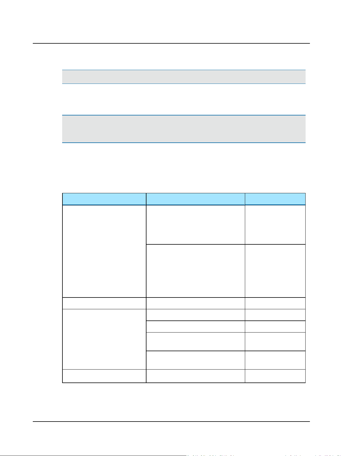
1. Click System Settings and click Administrator.
2. Click Browse... to browse to the desired folder.
Otometrics - ICS Impulse USB
51
Page 52
User Guide
Note• If selecting a folder on the network, ensure that the folder you select is configured for sharing.
3. Select the folder and click OK.
The new location for the folder displays in the OTOsuiteVestibular Storage Locations window.
Note• For each location that has been changed, new files will be stored at the new location. For example, if the loc-
ation has been changed for video files, new video recordings will be stored at the new location.
For each new location, existing files should be moved from the previous location to the new location.
16 Accessories
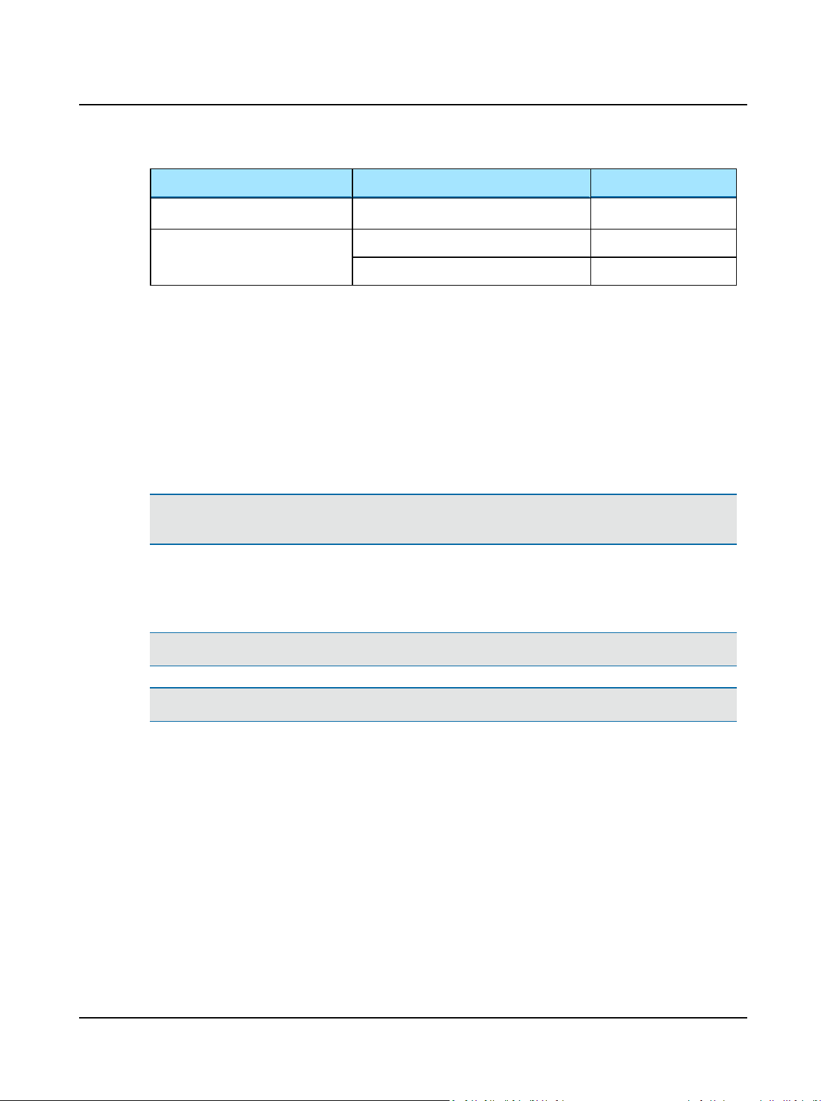
Accessories
Manuals/Videos ICS Impulse Quick Guide 7-50-11300-EN
7-50-11300-DE
7-50-11300-ES
7-50-11300-FR
7-50-11300-IT
ICS Impulse Training video 8-49-82700-DE
8-49-82700-EN
8-49-82700-ES
8-49-82700-FR
8-49-82700-IT
8-49-82700-US
Software OTOsuiteVestibular 8-49-90300
Goggles Face cushion 120/pkg 8-62-50200
Strap assembly 8-35-34200
Optical cleaning cloth
***Qty min 3***
Fixation dot
(2 sheets/pkg)
Synchronized Room Video Microsoft Life Cam USB Camera 2-25-08805
7590527
1-26-44000
52 Otometrics - ICS Impulse USB
Page 53
Accessories
Cables Cable clip 8-35-36900
Case/Mount Carrying case 8-35-36700
Wall mount 8-62-45600
17 Service, cleaning, and maintenance
The ICS Impulse System equipment does not require preventive maintenance. Observe the following recommended
guidelines regarding cleaning and maintenance.
• Keep the instrument clean and as free of dust as possible. Remove dust using a soft cloth or brush.
• If required, clean the goggle housing using a damp cloth moistened with a mild detergent and water solution. Do not
allow any moisture to get inside the goggles. Keep moisture away from the cooling fan.
User Guide
Caution• Never spray or immerse the goggle components with the cleaning solutions. This could contaminate the
electronics and/or optics.
• If required, clean the mirror and/or the camera lens using the supplied cleaning cloth. The presence of fingerprints on
the mirror surfaces could cause inaccurate pupil detection. If the camera or mirror is not clean, artifacts will be seen
during data collection.
Caution• Improper cleaning of either the mirror or the camera lens may scratch the surfaces.
Caution• A small cooling fan is inside the goggles housing. Keep the fan blades freefrom any obstruction.
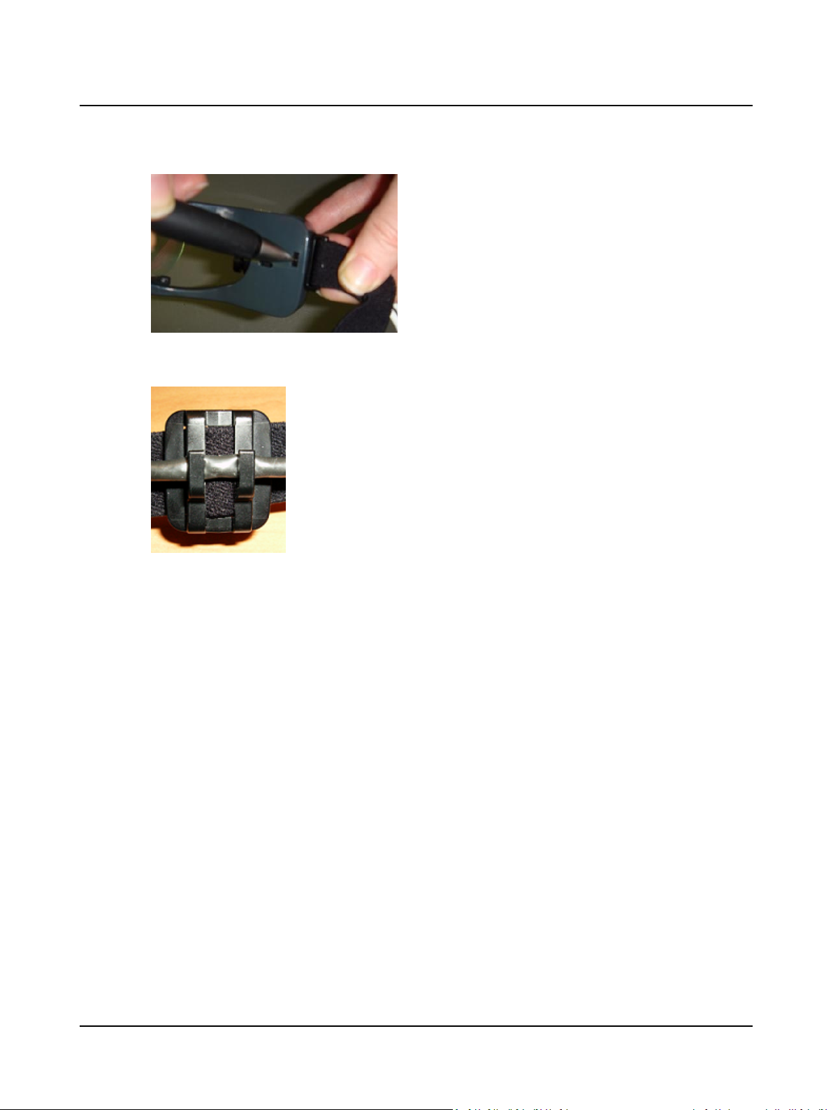
Replacing the strap
1. Remove the face cushion.
2. Use a pen to push the plastic clip down and pull out the strap clip attached to the goggle.
Otometrics - ICS Impulse USB
53
Page 54
User Guide
3. Repeat on the other side.
4. Remove the cable from both clips on the strap.
5. Obtain a new strap assembly
6. Clip the strap clips into each side of the goggle.
7. Attach the cable to both clips on the strap.
18 Other references
For more information, see the online Reference Manual in OTOsuiteVestibular, which contains detailed reference information about ICS Impulse USB . Also you can find more information in the ICS Impulse training video or at www.ic-
simpulse.com.
19 Standards
ICS Impulse is type 1085 from Natus Medical Denmark ApS
Interface
USB 2.0 to PC
54 Otometrics - ICS Impulse USB
Page 55

User Guide
Power Supply
Device is powered through USB (5 V DC, 500 mA)
Performance Characteristics
Inputs Monocular (Right eye only)
Sampling Rate 250 Hz for Head Impulse Test
Option of 30, 60 or 120 Hz for Video Recording
Eye Tracking 100 pixels x 100 pixels.
Software WindowsGraphical User Interface; High Performance Analysis Software; Database
Storage of Test Data; Sophisticated Patient and Test Data Management
Laser specifications
Wavelength Maximum 660 nm
Output power Maximum 0.9 mW
Warm-uptime
<1 min
OperatingMode
Continuous operation
Do not use the equipment in the presence of flammable anaesthetics (gases).
Dimensions
Goggles Length 7.25 in (18.4 cm)
Width 0.5 in (1.3 cm) to 1.75 in (4.4 cm)
Height 1.75 in (4.4 cm)
Weight
Goggles 2.1 oz (60 g)
Calibration
Calibration of the system is not required
Classification
Class II
Type B
Otometrics - ICS Impulse USB
55
Page 56

User Guide
OperatingEnvironment
Temperature
Rel. Humidity 30 to 90%, non-condensing
Air Pressure 700 hPa to 1060 hPa
Operations at temperatures below -20°C (-4° F) or above +60° C (140° F) may cause permanent damage to the device.
Storing and Handling
Temperature -20° C to +60° C (-4° F to +140° F)
Rel. Humidity <90%, non-condensing
Air Pressure 500 hPa to 1060 hPa
20 Manufacturer
Natus Medical Denmark ApS
9 Hoerskaetten, DK-2630 Taastrup
Denmark
+45 45 75 55 55
+45 45 75 55 59
www.natus.com
+15° C to +29 ° C (59° F to +84.2° F)
20.1 Responsibility of the manufacturer
The manufacturer is to be considered responsible for effects on safety, reliability, and performance of the equipment only
if:
• All assembly operations, extensions, re-adjustments, modifications or repairs are carried out by the equipment manufacturer or personnel authorized by the manufacturer.
• The electrical installation to which the equipment is connected complies with EN/IEC requirements.
• The equipment is used in accordance with the instructions for use.
The manufacturer reserves the right to disclaim all responsibility for the operating safety, reliability and performance of
equipment serviced or repaired by other parties.
21 Warning notes
This manual contains information and warnings, which must be followed to ensure the safe performance of the devices and
software covered by this manual. Local government rules and regulations, if applicable, should also be followed at all times.
56 Otometrics - ICS Impulse USB
Page 57
User Guide
Natus Medical Denmark ICS products are not designed to be used in conjunction with any devices not approved by Natus
Medical Denmark. Summation of combined unapproved parts could result in increased electrical leakage. All parts of the
ICS Impulse System are suitable for use within the patient environment.
When the ICS Impulse System is used in conjunction with a test device, make sure that all information, cautions, and warnings in the manual for the test device are followed.
For safety specifics concerning test modules and test devices, see the specific manuals.
1. There are no user-serviceable parts inside the ICS Impulse System goggles. For the sake of safety and in order not to
void the warranty, service and repair of electro-medical equipment should be carried out only by the equipment manufacturer or by service personnel at authorized workshops. In case of any defects, make a detailed description of the
defect(s) and contact your supplier. Do not use a defective device.
2. Keep the unit away from liquids. Do not allow moisture inside the unit.
3. Do not use the instrument in the presence of flammable anesthetics (gases).
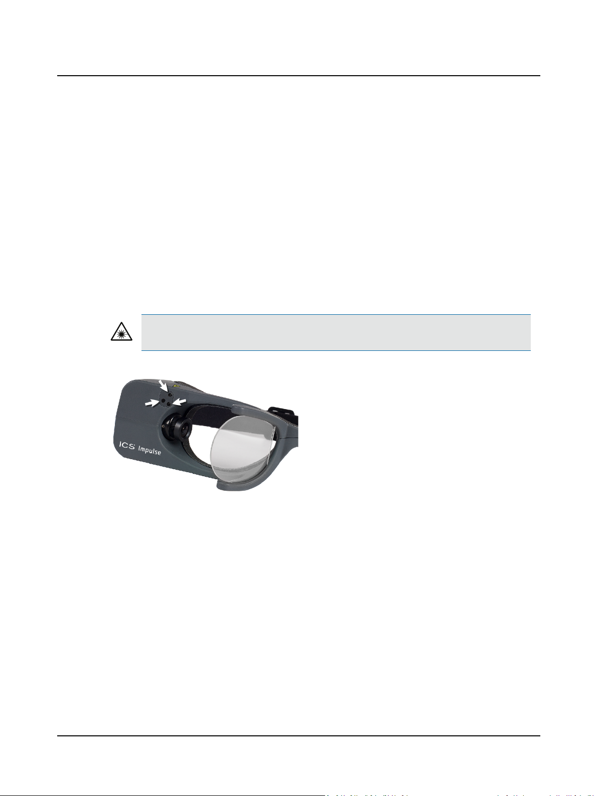
4. A Class 2 Laser product is used for calibration. The laser beam projects from the front of the goggles onto a solid surface.
Caution• Do not look directly at the lasers. Use of controls or adjustments, or performance of procedures
other than those specified herein, may result in hazardous radiation exposure.
5. It is recommended to install the unit in an environment that minimizes the amount of static electricity. For example,
anti-static carpeting is recommended.
6. No parts may be eaten, burnt, or in any way used for purposes other than the applications defined in the Intended Use
section of this manual.
7. The device can be disposed of as normal electronic waste, according to local regulations.
8. For safety reasons, accessories connected to the equipment's outlet fittings must be identical to the type supplied
with the system.
9. The device is disconnected from the mains by removingthe USB cable.
10. Do not touch non-medical parts, such as the laptop/computer or printer and the patient at the same time.
11. Exposure to electromagnetic fields can result in interference with the process of recording correct measurements. ICS
Impulse System camerasand gyroscopesare sensitive to electrical disturbances. Avoid static discharges and electromagnetic fields.
12. No defibrillators or high-frequency surgical equipment should be applied to the patient when connected to the ICS
Impulse System at any time.
13. Immediately discontinue use of the equipment if skin irritation or discomfort occurs.
Otometrics - ICS Impulse USB
57
Page 58
User Guide
14. Installation of any third party software (applications, programs, or utilities) other than those specified by Natus
Medical Denmark can compromise the safety or effectiveness of this system.
15. The ICS Impulse System needs to be installed and put into service according to the EMC information provided in this
manual. Portable and mobile RF communications equipment can affect medical electrical equipment. The ICS
Impulse System may be interfered with by other equipment with CISPR emission requirements.
16. The use of accessories and cables other than those specified for this device may result in increased emissions or
decreased immunity of the ICS Impulse System. Refer to the accessories list in the Reference Manual.
17. The ICS Impulse System should not be used adjacent to or stacked with other equipment and that if adjacent or
stacked use is necessary, the equipment or system must be observed to verify normal operation in the configuration
in which it will be used.
18. A small cooling fan is inside the goggles housing. In the unlikely event of the cooling fan vent being blocked, the tem-
perature of the goggles surface in contact with the patient may rise to 42.2° C.
19. Warning notes:
When connecting equipment to the USB connectors, the following must be considered:
• Equipment must be certified to relevant EN/IEC safety standards, e.g. EN/IEC 60950.
• Use of connected equipment in a patient environment, see Note 1. Ensure that the medical electrical system complies with the requirements of EN 60601-1 or IEC 60601-1 (2005), 3. ed.
Note 1: The ICS Impulse system is a part of an medical electrical system. When assembling an medical
electrical system , the person carrying out the assembly must take into account that connecting other
equipment that does not comply with the same safety requirements as the ICS Impulse system may lead
to a reduction in the overall safety level of the system. The ICS Impulse system is designed to ensure compliance with requirements in EN 60601-1 or IEC 60601-1 (2005), 3. ed. when the PC, printer, etc. are
placed out of reach of the patient, i.e. not closer than approx. 1.5 meters/5 ft.
22 Definition of symbols
ICS Impulse
System
CAUTION: Laser radiation. Do not stare into beam. Class 2 laser product.
Consult user manual for warnings and cautions.
Follow instructions for use.
58 Otometrics - ICS Impulse USB
Page 59
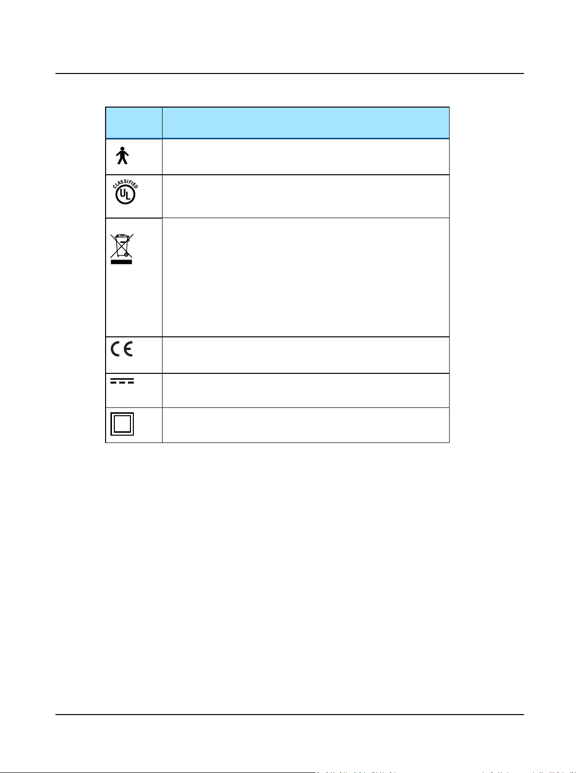
ICS Impulse
C
U
L
US
®
X X X X
System
User Guide
Complies with Type B requirements of IEC60601-1.
MEDICAL - General Medical Equipment as to electrical shock, fire and mechanical
hazards only in accordance with UL 60601-1, first edition, 2003 CAN/CSA-22.2 No.
601.1-M90.
Electronic equipment covered by the Directive 2002/96/EC on waste electrical
and electronic equipment (WEEE).
All electrical and electronic products, batteries, and accumulators must be taken
to separate collection at the end of their working life. This requirement applies in
the European Union. Do not dispose of these products as unsorted municipal
waste.
You can return your device and accessories to Natus Medical Denmark, or to any
Natus Medical Denmark supplier. You can also contact your local authorities for
advice on disposal.
Complies with Medical Devices Directive 93/42/EEC.
Suitable for direct current only.
(Applies to the goggles.)
Complies with Class II requirements of the safety standard IEC 60601-1.
22.1 Label locations
For an overview of the labels found on the ICS Impulse system components, refer to the Reference Manual.
23 Notes on EMC (Electromagnetic Compatibility)
• ICS Impulse USB is part of a medical electrical system and is thus subject to special safety precautions. For this reason,
the installation and operating instructions provided in this document should be followed closely.
• Portable and mobile high-frequency communication devices, such as mobile phones, may interfere with the functioning of ICS Impulse USB.
Otometrics - ICS Impulse USB
59
Page 60
User Guide
Guidance and manufacturer'sd eclaration - electromagnetic emissionsfor allequipment and systems
ICS Impulse USB is intended for use in the electromagnetic environment specified below. The user of ICS Impulse U SB should ensurethat it is used in such an
environment.
Emissions test Compliance Electromagnetic environment - guidance
RF emissions
CISPR 11
RF emissions
CISPR 11
Harmonic emissions IEC61000-3-2 ClassA
Voltagefluctu ations/flicker emissions IEC
61000-3-3
Group 1 ICS Impulse USB uses RF energyonly for its internalfunction. Therefore, itsRF emissions are
verylo w and arenot likely to cause any in terference in nearby electronic equipment.
ClassA ICS Impulse USB is suitable for use in all establishments oth er than domestic and th ose dir-
ectly con nected to the public low-voltagepower supply network that supp lies buildin gs
used for domestic p urpo ses.
Complies
Immunity- All Equipment and Systems
The ICS Impulse USB System wasnot tested for immunity to electromagnetic disturbances.
60 Otometrics - ICS Impulse USB
 Loading...