

Page 1

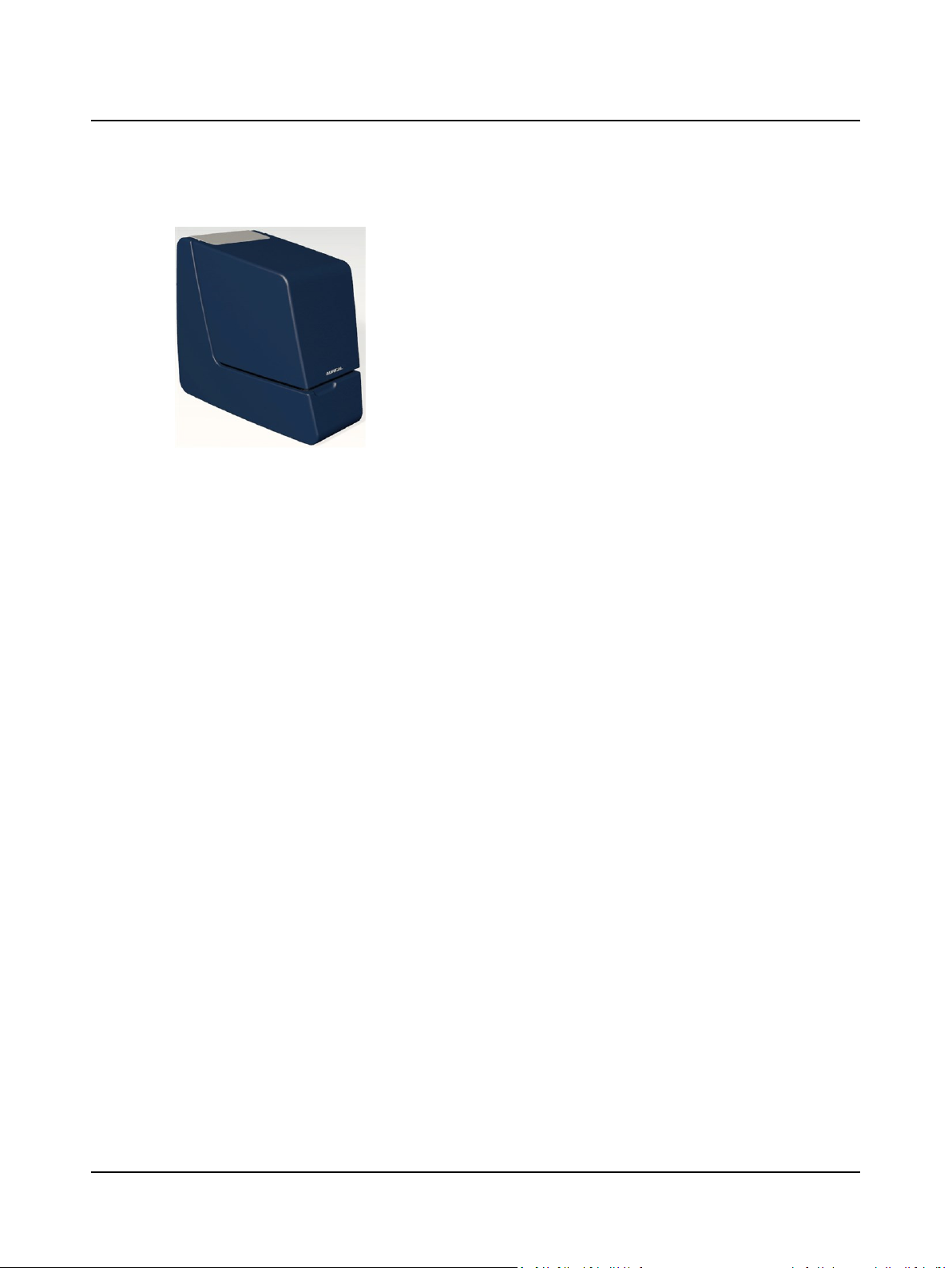
AURICALHIT and the
OTOsuite HITModule
Reference Manual
Doc. No. 7-50-1150-EN/06
Part No. 7-50-11500-EN
Page 2

Copyrightnotice
© 2012,2017GNOtometricsA/S. Allrights reserved. ® Otometrics,the OtometricsIcon,AURICAL,MADSEN, ICSand HORTMANN
are registered trademarks of GNOtometricsA/S in the U.S.A.and/or other countries.
Version release date
2017-03-12 (153432)
Technical support
Please contactyour supplier.
2
Otometrics - AURICALHIT
Page 3

Table of Contents
1 Introduction 5
1.1 Intended Use 5
1.2 Typographical conventions 6
1.2.1 Navigating this manual 6
2 AURICALHIT 7
2.1 Unpacking AURICALHIT 7
2.2 Installation 7
2.2.1 Connecting AURICALHIT 7
2.2.2 Initial calibration 7
2.3 The test chamber 7
2.3.1 Reference microphone 9
2.3.2 BTE adapter tube 9
2.3.3 The coupler assembly 9
2.3.4 Battery simulator 11
2.3.5 Cable groove 11
2.3.6 Elevation plate 11
2.3.7 Coupler microphone sockets 12
2.3.8 Sound absorbing foam lining 12
2.3.9 Main loudspeaker 12
2.3.10 Rear loudspeaker 12
2.3.11 The AURICALHIT lid 12
2.3.12 Telecoils 12
2.3.13 The AURICALHIT handle 13
2.4 The Accessory Box 14
3 Testing hearing instruments 15
3.1 Calibrating the reference microphone 15
3.2 Positioning the hearing instrument for testing 16
3.3 Traditional BTE hearing instruments 20
3.4 Thin-tube hearing instruments 21
3.5 ITE hearing instruments 22
3.6 Telecoil testing 24
3.7 Hearing instruments with wireless transmitters (e.g. FM) 24
3.8 Body-worn hearing instruments 26
3.9 Testing the hearing instrument with OTOsuite HIT 26
4 HIT FreeStyle testing 29
4.1 Navigating in HIT FreeStyle 29
5 Cleaning, Repair and Calibration 32
5.1 Cleaning 32
Otometrics - AURICALHIT
3.2.1 General guidelines for positioning the hearing instrument 16
3.2.2 Using the battery simulator 18
3.2.3 Coupler adapters 19
3.3.1 With BTE adapter tube 20
3.4.1 Using the HA-1 ITE, RIE, thin-tube adapter 21
3.9.1 How to perform a standard test 26
3.9.2 How to test the directional microphone 27
5.1.1 Cleaning the device 32
3
Page 4

5.1.2 Cleaning accessories 32
5.2 Service and repair 33
5.2.1 Replacing/updating the reference microphone 33
5.2.2 Replacing/updating the coupler microphone 33
5.2.3 Replacing floor lining 33
5.3 Calibration 34
5.3.1 How often is calibration necessary? 34
5.3.2 Environment Report 34
Procedure 34
5.3.3 Calibrating the coupler microphone 36
5.4 The battery simulator 37
6 Troubleshooting 38
7 Standards and Safety 39
7.1 AURICALHIT 39
7.2 Warning notes 39
7.3 The OTOsuite HIT Module 40
7.4 Manufacturer 41
7.4.1 Responsibility of the manufacturer 41
8 Technical specifications 42
Index 45
4 Otometrics - AURICALHIT
Page 5
1 Introduction
Hearing instruments
It is easy to position hearing instruments on snap-on couplers inside the AURICALHIT test chamber and it is easy to access
the hearing instruments in the test chamber during test without disturbing the test setup.
The battery pill types are recognized automatically, and the reference microphone ensures reliable positioning in the test
chamber.
Directionality
The Directionality feature provides for fast measurement of directionality and quality check of the hearing instruments.
AURICALHIT is designed for Hearing Instrument Testing and Coupler-Based Fitting.
AURICALHIT connects via USB to a computer running the OTOsuite software.
• With the OTOsuite HITModule you can perform traditional hearing instrument testing according to either the ANSI or IEC test protocols, and obtain a
consistent picture of every hearing instrument, regardless of manufacturer or
type.
• With the OTOsuite PMM Module you can perform Probe Microphone Measurements in a coupler for pre-programming and pre-fitting hearing instruments
without the client being present.
RECD
Real ear response can be recorded without having AURICALHIT at hand, and coupler-based fitting can be performed by
itself without using AURICALFreeFit.
Coupler-based fitting using RECD is a "coupler" mode as part of the PMM functionality for providing simple hearing instrument fitting. Coupler-based fitting is described in the AURICALFreeFit and the Probe Microphone Measurements User
Manual.
AURICALHIT supports stored coupler values which drastically reduces the need for measuring coupler responses.
NOAH integration
AURICALHIT can operate either as a stand-alone system, or under the NOAH software, which was developed by HIMSA as a
common software platform for programming and fitting hearing instruments. NOAH integrates client records, audiological
data and the dedicated fitting modules from various hearing instrument manufacturers.
1.1 Intended Use
AURICALHIT is intended for testing purposes by audiologists, hearing instrument dispensers, and other health care professionals in testing programmable hearing instruments.
Required qualifications
It is assumed that the user has a basic knowledge of how to compare the results of the hearing instrument tests with the
specifications from the hearing instrument manufacturer and to detect typical malfunctions of the hearing instrument.
Otometrics - AURICALHIT
5
Page 6

1 Introduction
1.2 Typographical conventions
The use of Warning, Caution and Note
To draw your attention to information regarding safe and appropriate use of the device or software, the manual uses precautionary statements as follows:
Warning • Indicates that there is a risk of death or serious injury to the user or patient.
Caution• Indicates that there is a risk of injury to the user or patient or risk of damage to data or the device.
Note•Indicates that you should take special notice.
1.2.1 Navigating this manual
Menus, icons and functions to select are shown in bold type, as for instance in:
• Click the Set options icon on the toolbar or select Tools > Options.
6 Otometrics - AURICALHIT
Page 7

2 AURICALHIT
2.1 Unpacking AURICALHIT
1. Unpack the device carefully.
When you unpack the device and accessories, it is a good idea to keep the packing material in which they were
delivered. If you need to send the device in for service, the original packing material will protect against damage during transport, etc.
2. Visually inspect the equipment for possible damage.
If damage has occurred, do not put the device into operation. Contact your local distributor for assistance.
3. Check with the packing list to make sure that you have received all necessary parts and accessories. If your package is
incomplete, contact your local distributor.
2.2 Installation
• Place AURICALHIT on an absolutely stable surface.
• In order to exclude ambient noise and to comply with the ANSI S3.22 standard, place the system in a moderately
quiet room.
2 AURICALHIT
2.2.1 Connecting AURICALHIT
1. Install OTOsuite on the PC. See the OTOsuite Installation Manual.
2. Connect the USB cable from the USB socket under AURICALHIT to a USB socket in the PC. AURICALHIT is powered by
the PC.
AURICALHIT is selected automatically in OTOsuite.
If you wish to use a demo device, select Tools > Configuration Wizard. Click Configure next to AURICALHIT, and
select Demo device.
2.2.2 Initial calibration
When you have connected AURICALHIT to the PC, you must perform an initial calibration of the reference microphone.
See Calibrating the reference microphone ► 15.
Calibration procedures and general recommendations about calibration are described in Calibration ► 34.
2.3 The test chamber
Using AURICALHIT and positioning hearing instruments in the test chamber are described in Testing hearing instruments
► 15.
Otometrics - AURICALHIT
7
Page 8
2 AURICALHIT
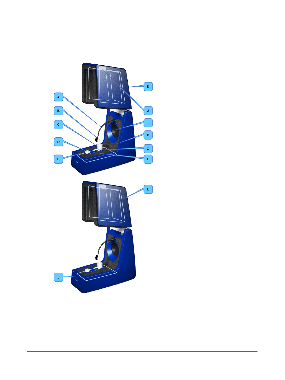
A. Reference microphone ► 9
B. BTE adapter tube ► 9
C. The coupler assembly ► 9
D. Battery simulator ► 11
E. Cable groove ► 11
F. Elevation plate ► 11
G. Coupler microphone sockets ► 12
H. Sound absorbing foam lining ► 12
I. Main loudspeaker ► 12
J. Rear loudspeaker ► 12
K. The AURICALHIT lid ► 12
L. Telecoils ► 12
8 Otometrics - AURICALHIT
Page 9
2.3.1 Reference microphone
The position of the reference microphone is easy to adjust. Make sure that the reference microphone does not come into
contact with AURICALHIT when you close the lid so that the microphone is not pushed out of place when you close the
lid for testing.
2 AURICALHIT
The AURICALHIT handle ► 13
(some models only)
The Accessory Box ► 14
2.3.2 BTE adapter tube
2.3.3 The coupler assembly
Coupler adapter
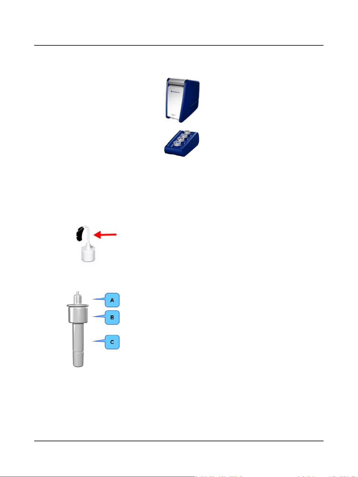
The Accessory Box provides a range of adapters for easy positioning of different types of hearing instruments.
The BTE adapter tube can be bent to correctly position the microphone or microphones of
the hearing instrument in relation to the main loudspeaker. It is used for verification of
BTE hearing instruments as well as for measuring the coupler portion of RECD.
The adapter tube is compliant with ANSI and IEC requirements.
The coupler assembly consists of the following parts:
A. Coupler adapter
B. Coupler cavity
C. Coupler microphone
Otometrics - AURICALHIT
9
Page 10

2 AURICALHIT
Coupler cavity
During tests in the test chamber, the hearing instrument is connected to a 2cc coupler cavity manufactured in accordance
with the ANSI standard. Alternatively, you can use an ear simulator.
Note•The ear simulator is not ANSI or IEC compliant, and is not recommended for RECD measurements.
You can use the Coupler Type icons in the toolbar to toggle between 2cc coupler and ear sim-
ulator. The selected coupler type is saved with measurements for later reference.
Coupler microphone
The coupler microphone is located in a coupler bottom piece which must be attached to the coupler cavity.
You can use the coupler microphone either directly in AURICALHIT or in the Accessory Box.
The system automatically detects and activates the coupler microphone regardless of which setup you are using.
AURICALHIT
A. BTE testing - Low coupler position
B. ITE, RIE, thin-tube testing - High coupler position
The Accessory Box
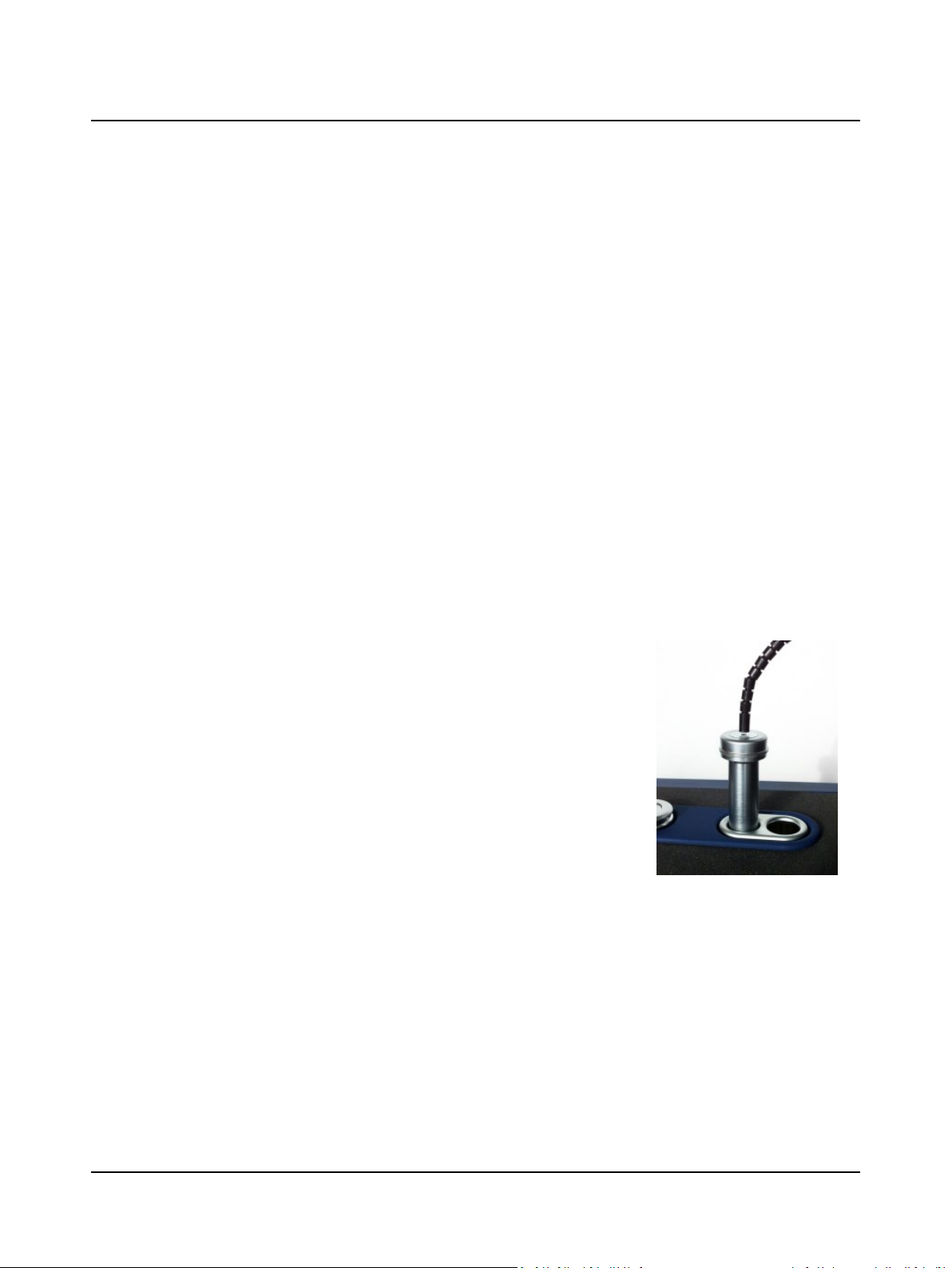
Connect the mini-jack cable from the Accessory Box to the mini-jack socket under AURICALHIT, and insert the coupler
microphone in the microphone socket in the Accessory Box.
A. Wireless hearing instrument testing
10 Otometrics - AURICALHIT
Page 11
The purpose of using the coupler microphone in the Accessory Box is to acoustically separate the input signal from the
hearing instrument. This makes it possible to verify the external input device independently of the hearing instrument,
and is mainly used for testing devices such as FM and Bluetooth transmitters.
2.3.4 Battery simulator
Using a battery simulator is highly recommended because it ensures that the hearing instrument is powered with the correct voltage and you avoid unnecessary battery waste for the purpose of coupler measurements.
See Using the battery simulator ► 18.
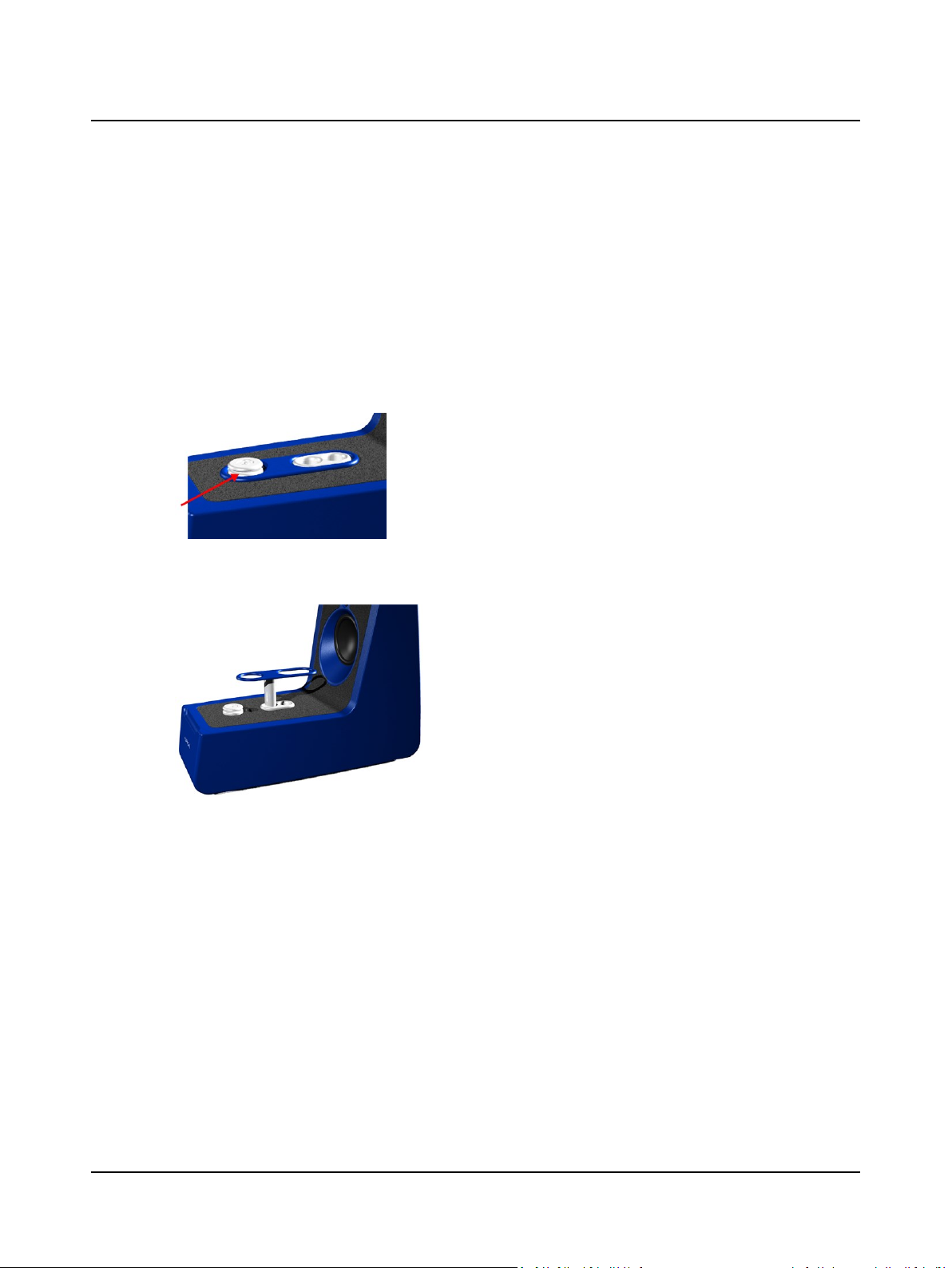
2.3.5 Cable groove
2 AURICALHIT
Wrap the programming cable of the hearing instrument once around the
cable groove. This prevents the hearing instrument from being pulled
out of place when you close the lid for testing.
2.3.6 Elevation plate
• To use the plate, lift it up from its recess and place it in the high-position coupler socket.
Use the elevation plate to facilitate positioning of wireless transmitters
and body worn hearing instruments at a level where the microphone or
microphones are approximately centered in relation to the loudspeaker.
Otometrics - AURICALHIT
11
Page 12
2 AURICALHIT
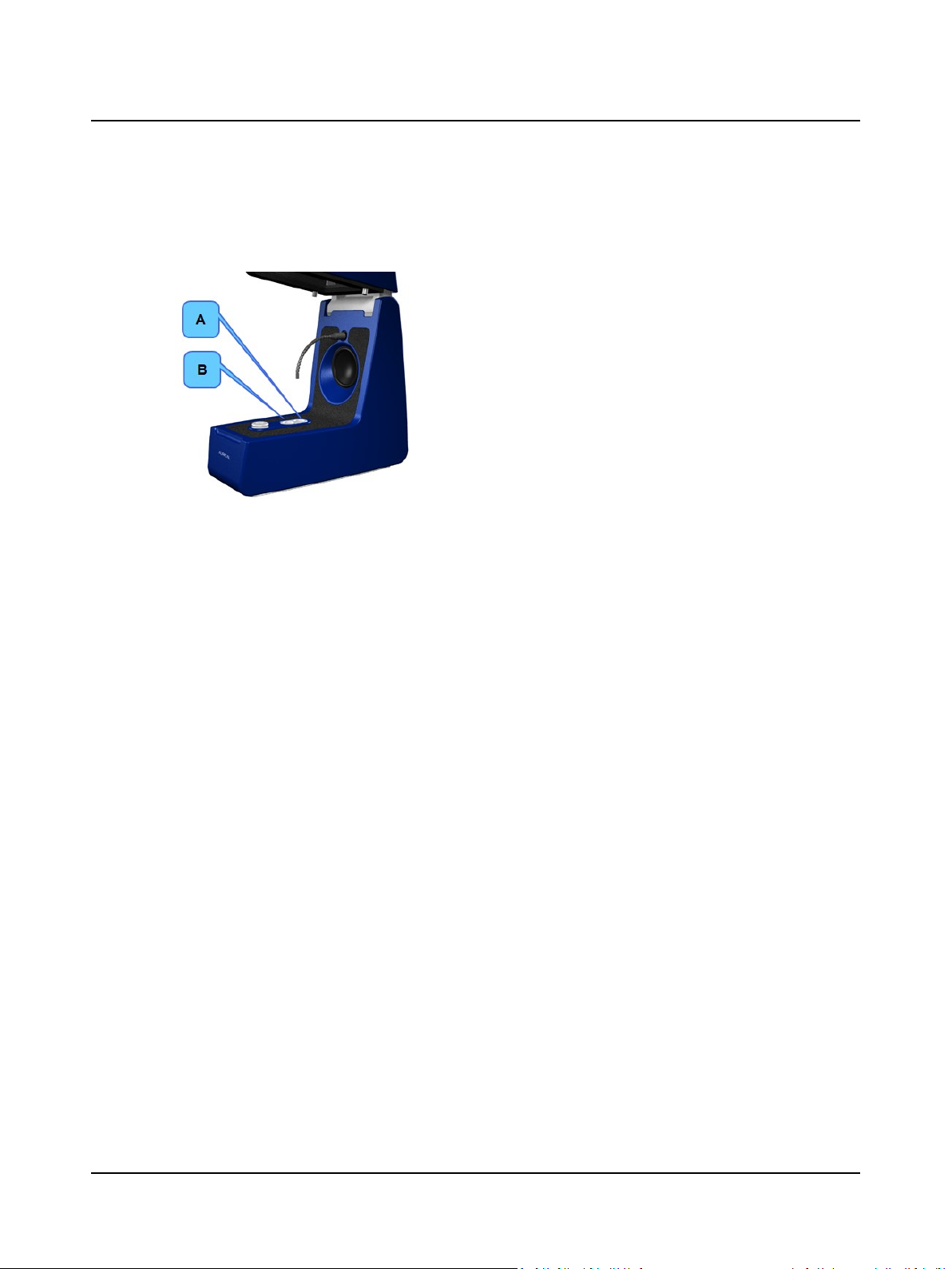
2.3.7 Coupler microphone sockets
AURICALHIT
2.3.8 Sound absorbing foam lining
AURICALHIT is lined with sound absorbing foam which is specifically designed to enhance the acoustic performance. Do
not remove any foam before measuring.
A. BTE testing - Low coupler position
B. ITE, RIE, thin-tube testing - High coupler position
2.3.9 Main loudspeaker
The main loudspeaker is used for presenting regular acoustic test signals.
2.3.10 Rear loudspeaker
The rear loudspeaker presents the signal from behind the hearing instruments and is used for directional microphone testing.
2.3.11 The AURICALHIT lid
The lid of AURICALHIT has a closing mechanism that prevents the lid from slamming shut, which could upset the position
of the hearing instrument for testing.
Opening the lid
To open the lid, use only one hand to lift the lid gently.
Closing the lid
To close the lid, place your hand on the lid and press gently until the closing mechanism takes over the action.
2.3.12 Telecoils
4 induction loops are fitted in AURICALHIT for testing telecoil functioning:
BTE testing ITE testing
12 Otometrics - AURICALHIT
Page 13
2.3.13 The AURICALHIT handle
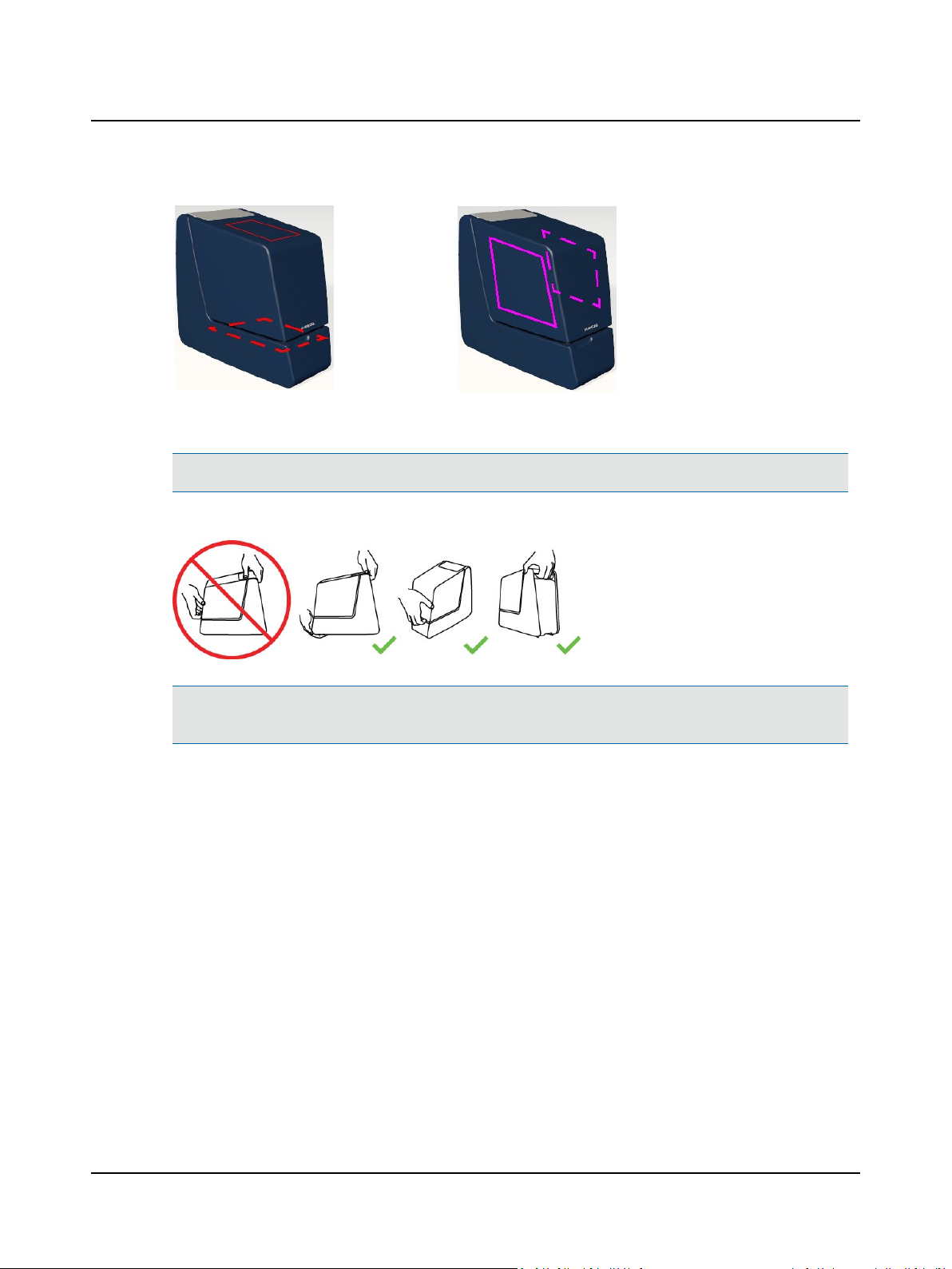
Note•This only applies to models equipped with a carrying handle.
The handle is designed for carrying AURICALHIT.
2 AURICALHIT
Caution• If you carry AURICALHIT by its handle, do not use your other hand to support it by the lid, as this may
cause the lid to open and squeeze your fingers.
Otometrics - AURICALHIT
13
Page 14
2 AURICALHIT
2.4 The Accessory Box
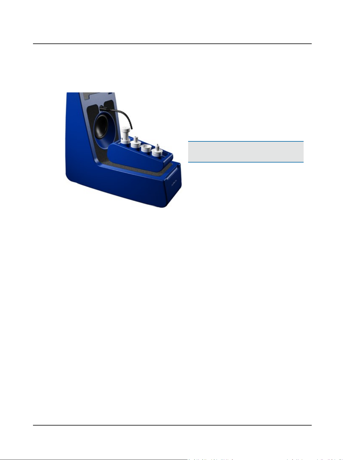
The Accessory Box is suited for storing coupler adapters,
battery simulators, etc., and fits in the test chamber when
not in use.
The Accessory Box serves as holder for the coupler microphone for testing hearing instruments outside
AURICALHIT. See The coupler assembly ► 9.
Caution• Do not place the Accessory Box inside
AURICALHIT during transportation.
14 Otometrics - AURICALHIT
Page 15
3 Testing hearing instruments
With AURICALHIT and the OTOsuite HITModule you can test the performance of hearing instruments according to both
ANSI and IEC standards. You can also perform coupler-based fitting as described in the AURICALFreeFit and the Probe
Microphone Measurements User Manual.
Testing a hearing instrument involves the following main tasks:
1. Calibrating the reference microphone
Otometrics recommends that you calibrate the reference microphone daily or weekly. Set up the interval to suit your purposes. See Calibrating the reference microphone ► 15.
2. Positioning the hearing instrument
General instructions are described in
• Traditional BTE hearing instruments ► 20
• Thin-tube hearing instruments ► 21
• ITE hearing instruments ► 22
3. Testing
When you have positioned the hearing instrument correctly, you can test it using the OTOsuite HIT module as described
in Testing the hearing instrument with OTOsuite HIT ► 26, or you can perform coupler-based fitting as described in the
AURICALFreeFit and the Probe Microphone Measurements documentation.
3 Testing hearing instruments
3.1 Calibrating the reference microphone
1. Launch OTOsuite and select the HIT module in the Navigation
panel.
2. Position the microphones in the center of the test chamber.
Otometrics - AURICALHIT
15
Page 16
3 Testing hearing instruments
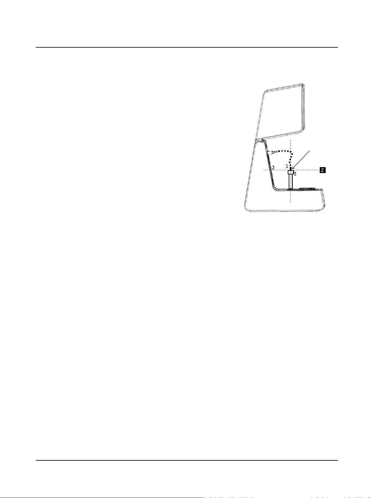
3. Position the reference microphone (1) pointing straight down from
above and centered 1-2 millimeters above the coupler measurement microphone (3).
4. During calibration the microphones must have the exact same distance to the main loudspeaker (2), along the Z axis. You can ensure
this by looking at the test chamber from the side when you adjust
the reference microphone position for calibration.
5. Close the lid.
6. Select Tools> AURICALHIT Calibration > Reference Microphone.
7. Follow the on-screen instructions.
3.2 Positioning the hearing instrument for testing
How you position the hearing instrument for testing in the test chamber depends on the type of hearing instrument or
device you wish to test.
Regardless of form factor (the type of hearing instrument), the only two important things to remember are:
• Aligning directional microphones along the loudspeaker axis.
• Positioning the reference microphone as close as possible to the front microphone of the hearing instrument without
touching it.
Single-microphone omni mode:
If the hearing instrument is not capable of single-microphone omni mode, it is recommended that you position the
hearing instrument at a 90° angle so that the distance is the same between the AURICALHIT main loudspeaker and
the two hearing instrument microphones.This also means that you must reposition the hearing instrument in the
standard position before directional measurements are performed.
3.2.1 General guidelines for positioning the hearing instrument
The absolute position of the hearing instrument is not critical, as long as the reference microphone is correctly positioned.
You can position the hearing instrument to perform all standard hearing instrument tests without repositioning the hearing instrument between the individual tests:
• acoustic measurements,
• inductive telecoil measurements,
• directional microphone test.
1. Positioning the hearing instrument
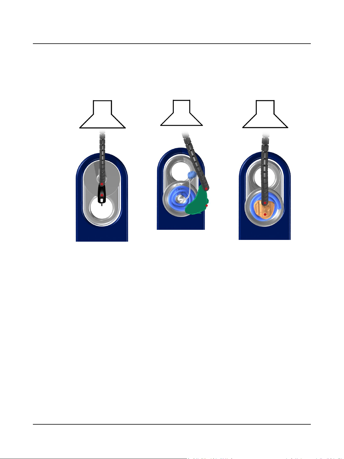
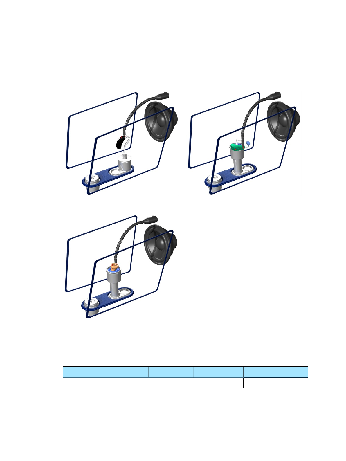
– Angle or turn the hearing instrument so that the front microphone (1) faces the main loudspeaker as it would
when worn on a person’s ear.
16 Otometrics - AURICALHIT
Page 17
3 Testing hearing instruments
– Position the hearing instrument so that a line through the front and rear directional microphones coincide with
the loudspeaker axis.
BTE Thin tube and RIE ITE
2. Positioning the reference microphone
– As a rule of thumb, position the reference microphone as close as possible to the front microphone of the hearing
instrument without actually touching it.
Maximum permitted distances are:
Vertically (Y axis) 8mm (above)
Sideways (X axis) ±12mm
Back-to-front (Z axis) ±3mm
Otometrics - AURICALHIT
17
Page 18
3 Testing hearing instruments
BTE Thin tube
ITE
3.2.2 Using the battery simulator
1. Select a battery simulator and insert it in the hearing instrument.
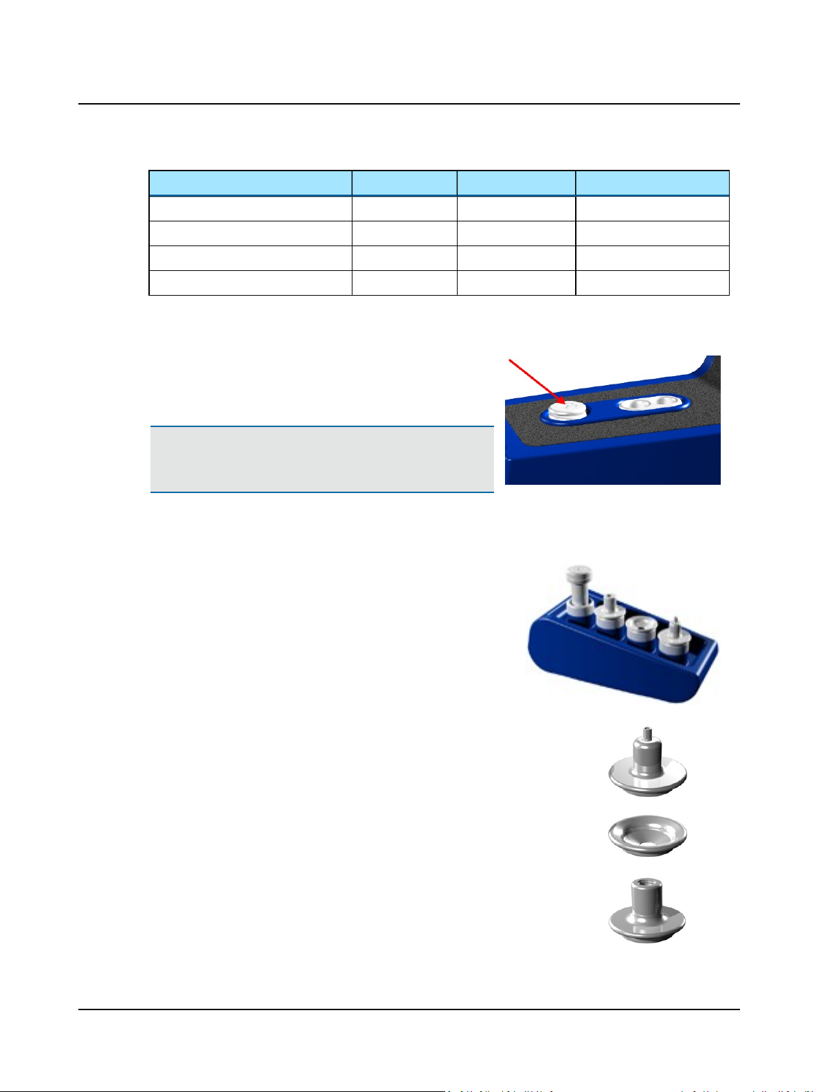
With AURICALHIT you receive a set of color-coded battery simulators, which are used to power the hearing instrument. They are also used as probes for measuring the power consumption.
Color code Size IEC ANSI
Red 5 PR63 7012ZD
18 Otometrics - AURICALHIT
Page 19
3 Testing hearing instruments
Color code Size IEC ANSI
Yellow 10 PR70 7005ZD
Brown 312 PR41 7002ZD
Orange 13 PR48 7000ZD
Blue 675 PR44 7003ZD
The metal strip between the battery simulator and the handle fits between the battery door and the hearing instrument casing.
2. Insert the mini-jack connector of the battery simulator in the battery simulator socket in the test chamber.
AURICALHIT automatically detects the battery simulator.
Caution• When you have connected the battery simulator, make
sure that it does not touch other metal parts as this may shortcircuit the system.
3.2.3 Coupler adapters
Adapters for use with the coupler are snapped onto the coupler cavity.
The adapters in the Accessory Box make it easy to position hearing instruments in the test chamber for testing
• HA-2 (BTE)
Traditional BTE hearing instruments ► 20
• HA-1 (ITE, RIE, thin-tube)
Thin-tube hearing instruments ► 21 and ITE hearing instruments ► 22
• Thin-tube hearing instruments ► 21
Otometrics - AURICALHIT
19
Page 20
3 Testing hearing instruments
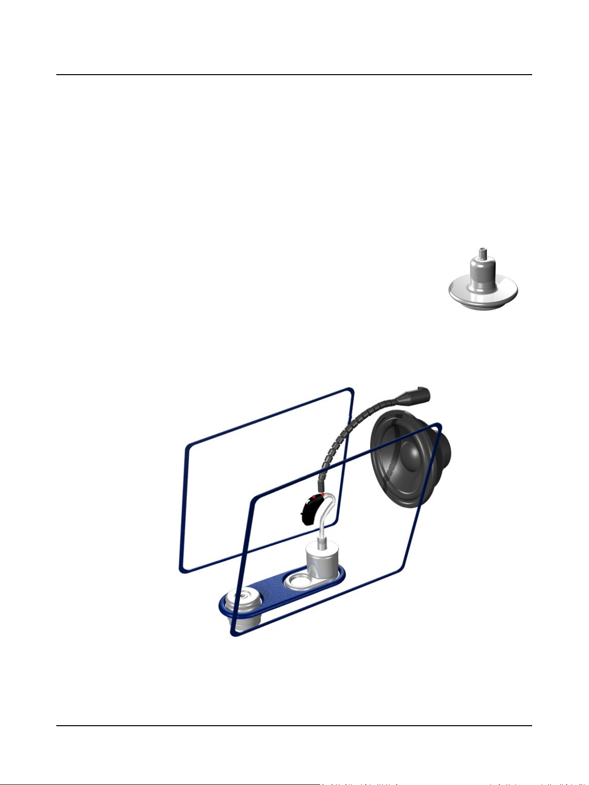
To fix the hearing instrument on the adapter, snap the adapter off the coupler cavity, and attach the hearing instrument to
the adapter outside the test chamber.
3.3 Traditional BTE hearing instruments
This procedure applies to any type of standard BTE hearing instruments with traditional ear molds.
Positioning the hearing instrument for directional testing is described in General guidelines for positioning the hearing
instrument ► 16.
3.3.1 With BTE adapter tube
1. Attach the BTE adapter tube to the tube stub on the HA-2 BTE adapter.
The tube must completely cover the tube stub on the adapter.
If a metal wire protrudes from the BTE adapter tube, turn the tube
upside down or use a new one.
2. Attach the hearing instrument to the free end of the BTE adapter tube
so that the metal wires in the tube align with the sides of the hearing
instrument.
3. Click the adapter with hearing instrument into place on the coupler and
place the coupler in the low position in AURICALHIT.
.
20 Otometrics - AURICALHIT
Page 21
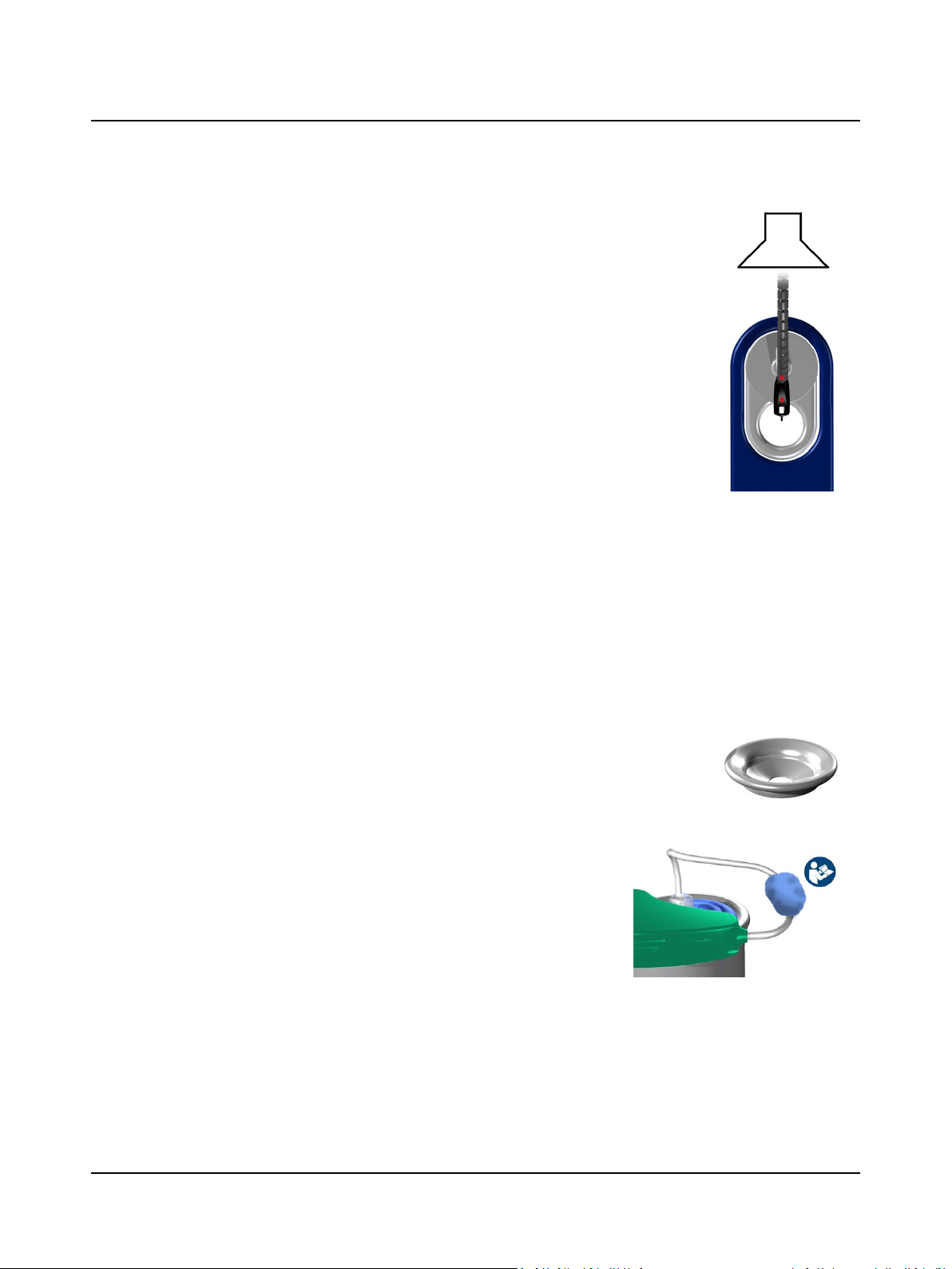
4. Align the microphones along the loudspeaker axis.
5. Position the reference microphone as close as possible to the front
microphone of the hearing instrument without touching.
6. Close the lid. You are ready to start testing.
3.4 Thin-tube hearing instruments
This type of procedure applies to any type of thin-tube hearing instruments, including instruments with the Receiver In
the Ear (RIE)/Receiver In the Canal (RIC), and pre-bent tubing.
Positioning the hearing instrument for directional testing is described in General guidelines for positioning the hearing
instrument ► 16.
3 Testing hearing instruments
3.4.1 Using the HA-1 ITE, RIE, thin-tube adapter
1. Remove the dome or tulip ear piece from the thin tube.
2. Wrap a thin roll of acoustic putty around the end of the thin tube.
3. Place the thin tube in the center of the hole in the HA-1 adapter so that
the thin tube’s entry hole is flush with the underside of the adapter.
4. Press the acoustic putty firmly around the thin tube.
5. Position the hearing instrument horizontally on a piece of acoustic putty
on the surface of the adapter so that the receiver part and the tubing
are not subjected to twisting or excessive force.
6. If you place some acoustic putty on the receiver wire, this will shift its
resonance frequency and prevent the wire from vibrating and creating
feedback during testing.
7. Click the adapter with hearing instrument into place on the coupler and
place the coupler in the high position in AURICALHIT.
Otometrics - AURICALHIT
21
Page 22
3 Testing hearing instruments
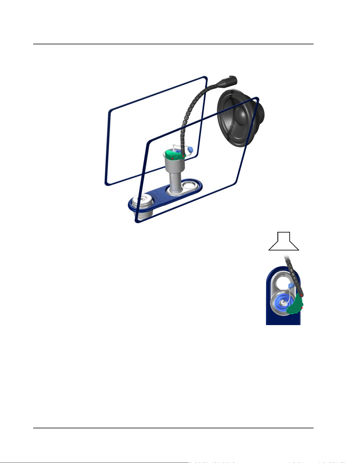
8. Align the microphones along the loudspeaker axis.
9. Position the reference microphone as close as possible to the front
microphone of the hearing instrument without touching.
10. Close the lid. You are ready to start testing.
3.5 ITE hearing instruments
This procedure applies to any type of custom hearing instruments, including ITE (In The Ear), ITC (In The Canal), CIC (Completely In the Canal).
Positioning the hearing instrument for directional testing is described in General guidelines for positioning the hearing
instrument ► 16.
1. Wrap a thin roll of acoustic putty around the receiver end of the hearing
instrument.
22 Otometrics - AURICALHIT
Page 23
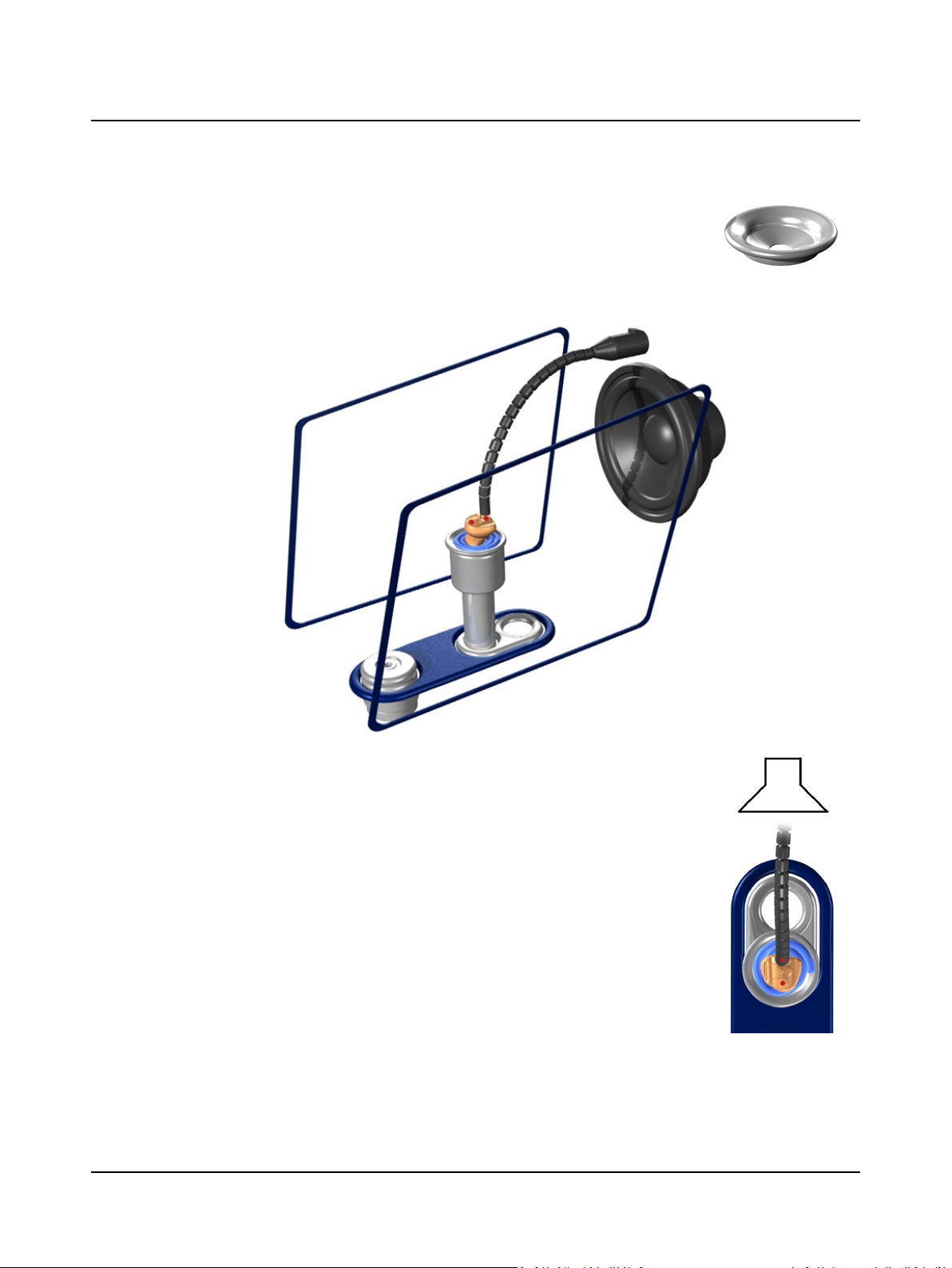
2. Place the receiver end in the center of the hole in the HA-1 adapter so
that the receiver end’s entry hole is flush with the underside of the
adapter.
3. Click the adapter with hearing instrument into place on the coupler and
place the coupler in the high position in AURICALHIT.
3 Testing hearing instruments
4. Align the microphones along the loudspeaker axis.
5. Position the reference microphone as close as possible to the front
microphone of the hearing instrument without touching.
6. Close the lid. You are ready to start testing.
Otometrics - AURICALHIT
23
Page 24

3 Testing hearing instruments
3.6 Telecoil testing
1. Position the hearing instrument in AURICALHIT as described in Traditional BTE hearing instruments ► 20, Thin-
tube hearing instruments ► 21 or ITE hearing instruments ► 22, so that the maximum field strength will be
achieved for the hearing instrument.
During telecoil testing AURICALHIT automatically detects the orientation of the hearing instrument.
2. Enable telecoil mode in the hearing instrument.
3. Close the lid and start testing.
3.7 Hearing instruments with wireless transmitters (e.g. FM)
When you test hearing instruments with wireless sound transmission, it is sometimes necessary to separate the input
device (transmitter) from the output device (receiver).
• To do so, place the transmitter in AURICALHIT and the receiver on the coupler microphone in the Accessory Box.
• To set up the Accessory Box, see The coupler assembly ► 9.
This procedure applies to hearing instruments with FM functionality. Use the procedure to verify that the FM system is correctly adjusted for transparency and FM advantage.
The FM verification measurements (reference, transparency and FM advantage measurements) involve coupler measurements both inside and outside the test chamber.
What you need for testing
• AURICALHIT
• An FM transmitter
• Hearing instrument with FM receiver
• Coupler assembly (adapter, coupler cavity and coupler microphone) placed in Accessory Box
• Coupler cable between Accessory Box and AURICALHIT
• Insulating pad under Accessory Box
• Acoustic putty (sealing material), such as Bostik Blu-Tack™
The measurement procedures described below serve as a guideline to show the intended workflow. This includes a
description of how to use the two special tests for FM Sequence testing with the Feature-2-Benefit functionality in the
OTOsuite PMM module.
For detailed instructions on FM and hearing instrument settings, as well as interpretation of these measurements, see the
documentation provided by the manufacturer of the specific FM device.
Use the two special tests for FM testing in the OTOsuite PMM module. You can use these tests to automatically collect
and compare the relevant measurements for FM transparency and advantage. These special tests are based on a traditional
65dBSPL speech signal for reference and transparency, and an 80dBSPL speech signal for FM advantage.
Perform reference measurements
1. To perform reference measurements, position the hearing instrument as described in Traditional BTE hearing instru-
ments ► 20, Thin-tube hearing instruments ► 21 and ITE hearing instruments ► 22. Leave the hearing instru-
ment placed on the coupler assembly in AURICALHIT.
2. Set the hearing instrument to FM+HI mode.
24 Otometrics - AURICALHIT
Page 25
3 Testing hearing instruments
3. Make sure that only the hearing instrument receives an input signal by muffling the FM transmitter microphone.
4. In the OTOsuiteTest Selector select the special test FM Reference Sequence - HI in AURICALHIT on the PMM tab.
The FreeStyle test screen in PMM is launched.
5. Close AURICALHIT and click the Sequence button in the Control Panel to measure curves 1 and 3.
Perform FM transparency and FM advantage measurements
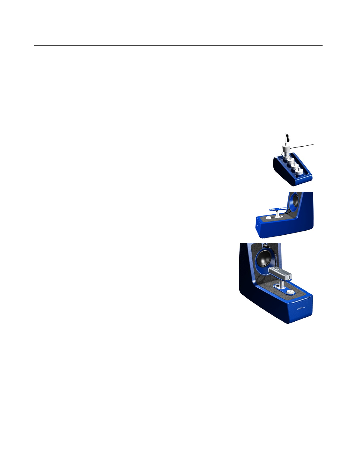
1. Connect the coupler cable from the Accessory Box to AURICALHIT.
2. Place the hearing instrument setup in the top position coupler hole of
the Accessory Box and place the Accessory Box on an insulating pad to
prevent noise and vibration from influencing the test.
3. Raise the elevation plate in the test chamber.
4. Make sure that you have removed the material used to muffle the FM
transmitter microphone for the reference measurements.
For FM transmitter with built-in microphone:
– Place the FM transmitter on the elevation plate in the test cham-
ber. If the transmitter has two or more microphones for directionality, align them along the loudspeaker axis.
For FM transmitter with lapel microphone:
– If the FM transmitter is equipped with a lapel microphone, run the
cable into the test chamber and fix the microphone to the elevation
plate.
Otometrics - AURICALHIT
25
Page 26
3 Testing hearing instruments
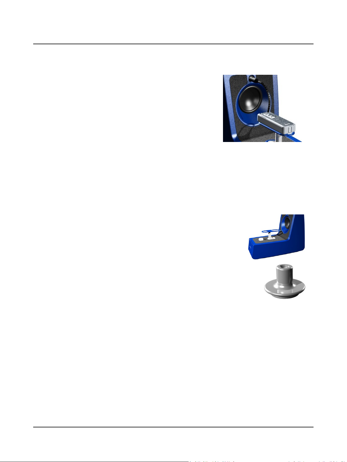
5. Position the reference microphone as close as possible to the microphone of the FM transmitter, but without touching.
6. In the OTOsuiteTest Selector select the special test FM Transparency
& Advantage Sequence - HI outside AURICALHIT on the PMM tab.
7. Close the lid and click the Sequence button in the Control Panel to
measure curves 2 and 4.
8. Check the results in the dB Gain Difference graphs in the Feature-2-
Benefit view.
3.8 Body-worn hearing instruments
This procedure applies to body-worn hearing instruments.
What you need for testing
• Coupler assembly (coupler cavity and coupler microphone) in Accessory Box
• Adapter for body-worn hearing instrument
• Coupler cable between Accessory Box and AURICALHIT
1. Raise the elevation plate in AURICALHIT.
2. Place the body-worn device on the elevation plate in the test chamber. If the device
has two or more microphones for directionality, align them along the loudspeaker
axis.
3. Remove the ear mold, if any, from the ear piece and attach the ear piece to the
adapter.
4. Connect the coupler cable from the Accessory Box to AURICALHIT.
5. Place the ear piece setup in the top position coupler hole of the Accessory Box.
6. Close the lid. You are ready to start testing.
3.9 Testing the hearing instrument with OTOsuite HIT
When you have positioned the hearing instrument, you are ready to start testing.
• To perform standard hearing instrument testing, see How to perform a standard test ► 26.
• To perform coupler-based fitting, see the AURICAL FreeFit and the Probe Microphone Measurements manual.
3.9.1 How to perform a standard test
With OTOsuite you can perform standard electro-acoustic verification of hearing instruments according to the latest ANSI
and IEC standards. You can also customize the available options and save them as user tests or start-up settings.
The procedure
1. Launch the fitting software for the hearing instrument so that you can control its parameters.
2. Launch OTOsuite and select HIT in the Navigation panel.
26 Otometrics - AURICALHIT
Page 27
3 Testing hearing instruments
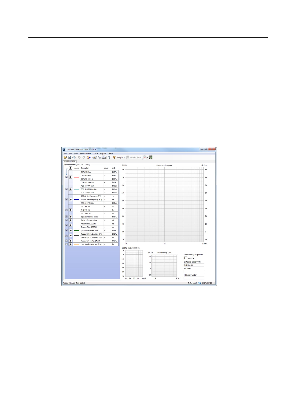
3. Open the Test Selector and select the ANSI or IEC special test.
4. If OTOsuite is used without Noah, you can fill out the Hearing Instrument fields in the lower right corner of the
Standard Tests screen. These fields are filled in automatically when you use OTOsuite with Noah together with the fit-
ting software for the hearing instrument.
5. Position the hearing instrument so that it is ready for testing, and switch it on.
6. If you wish to measure the Battery Consumption, make sure that you connect the battery simulator.
7. Close the lid.
8. If needed, click the arrow buttons in the Measurements table to include the individual tests you wish to perform.
9. Click the Start button in the top left corner of the Measurements table.
This will start a sequence of selected tests.
10. Make sure that you follow the on-screen instructions.
11. If you wish to redo an individual test, click on the Start button next to the test.
3.9.2 How to test the directional microphone
Directionality measurements as described in the hearing instrument test standards cannot be performed with regular desktop test chambers such as AURICALHIT. Such measurements require large anechoic chambers. Small test chambers always
exhibit acoustic reflections that obscure the true directional behavior of the hearing instrument.
However, in AURICALHIT you can make a functional test of the directional microphone in a hearing instrument. In this
test, the signal is first presented to the front of the hearing instrument and then to the back of the hearing instrument.
This is done automatically when you start a directional test. The signal used for this test is a flat spectrum Broad Band
Noise, band-pass filtered between 750 Hz and 5kHz, and presented at 70dBSPL.
Otometrics - AURICALHIT
27
Page 28

3 Testing hearing instruments
The procedure
1. Position the hearing instrument as described in Traditional BTE hearing instruments ► 20, Thin-tube hearing instru-
ments ► 21 and ITE hearing instruments ► 22 depending on the type of hearing instrument.
2. In the field Directionality Adaptation in the OTOsuite HIT module, you can define the duration of the signal present-
ation before the actual measurement is made. This value accommodates any adaptational behavior of the hearing
instrument. Adaptive directionality often takes 10 to 15 seconds or more before the directionality of the hearing
instrument is fully efficient.
3. You can either combine the Directional Test with your standard test sequence by checking the sequence checkbox,
or run it separately by clicking the Start button.
The result
The Directional Test result is shown as a 1/3 octave curve of the difference between the measurement with noise presen-
ted from the main loudspeaker and the measurement with noise presented from the rear loudspeaker. The numerical directionality result shown in the Measurements table indicates the average front/back difference in the measured
frequency range.
The Measurements table also includes the adaptation interval used in seconds.
28 Otometrics - AURICALHIT
Page 29
4 HIT FreeStyle testing
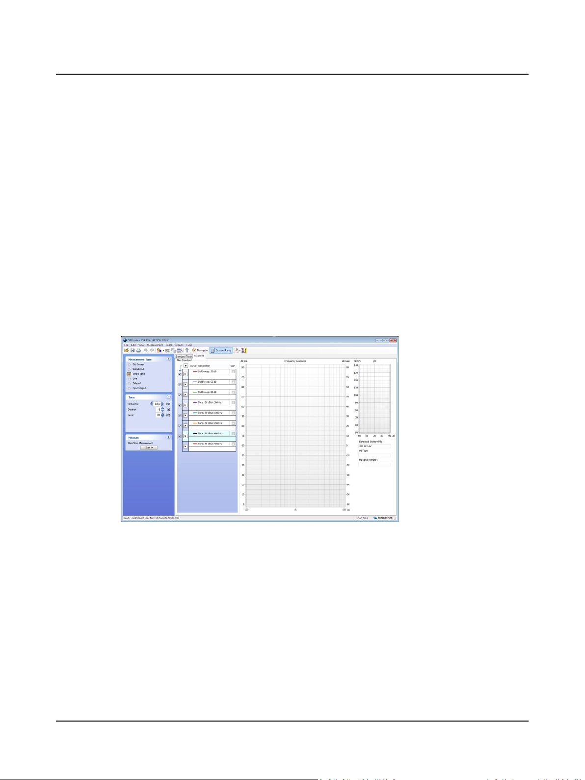
The HIT FreeStyle test feature provides you with a supplementary toolbox to the standard HIT tests.
The standard tests focus on testing hearing instruments according to the latest ANSI and IEC standards, whereas the HIT
FreeStyle test provides you with a variety of tests for use in demonstrating and verifying hearing instrument fitting and features to fit specific needs in the clinic.
The procedure
1. Launch OTOsuite and select HIT in the Navigation panel.
2. If needed, open the Test Selector and select a suitable user test.
3. If OTOsuite is used without Noah, you can fill out the Hearing Instrument fields in the lower right corner of the
Standard Tests screen. These fields are filled in automatically when you use OTOsuite with Noah together with the fit-
ting software for the hearing instrument.
4. Position the hearing instrument as described in Testing hearing instruments ► 15, so that it is ready for testing.
5. Close the lid.
6. Click the Start button in the top left corner of the Measurements table.
This will start the selected test(s).
4 HIT FreeStyle testing
4.1 Navigating in HIT FreeStyle
The Measurements table
You can use the measurement table straight away without any predefined settings. The table will be populated with the
tests as you perform them. You define the tests by clicking your selections in the Control Panel. You will find additional settings available in the Options dialog, when you select Tools > Options.
Customizing the testtable
1. You can customize different measurement tables which you can save and reload as user tests. This also allows you to
start a sequence of measurements.
Otometrics - AURICALHIT
29
Page 30
4 HIT FreeStyle testing
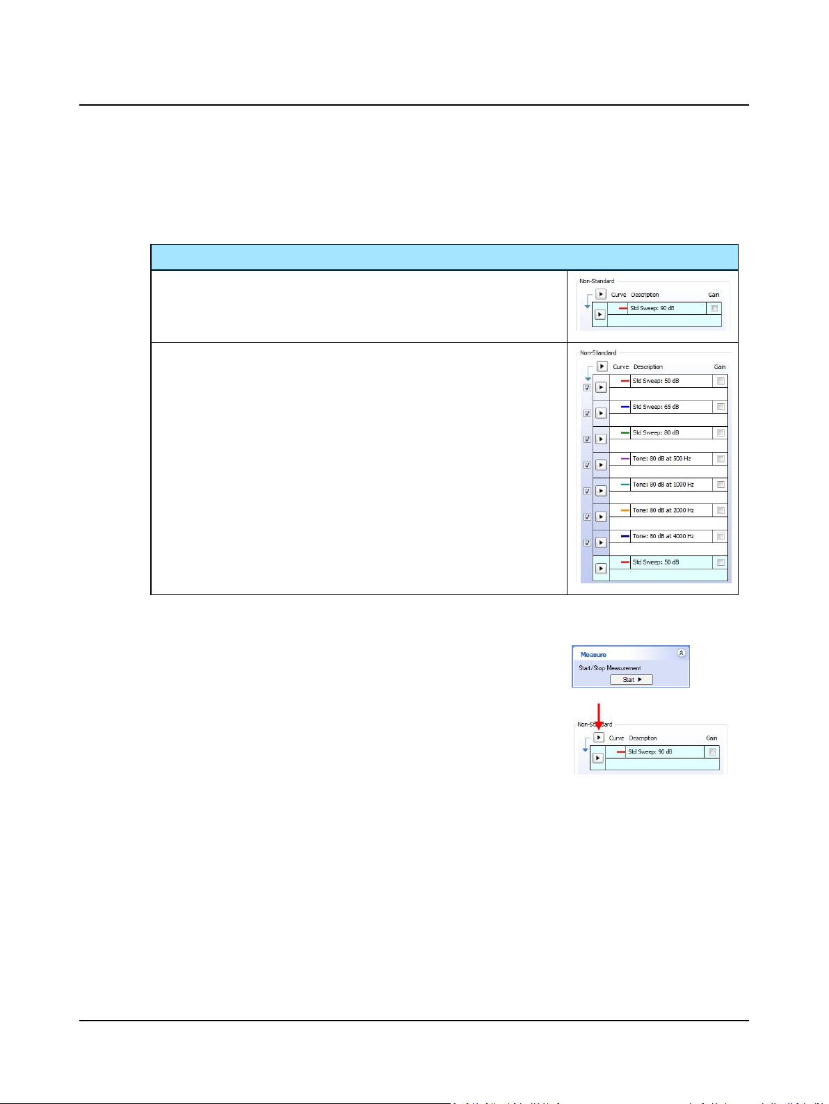
2. You can add tests to or delete tests from a sequence. To add a test to a sequence, simply right-click the test in the
table and select Add Test to Sequence.
3. You can change the order in which the tests are organized in the measurement table by moving them up or down.
Right-click on the test and select.
Example
Before you start adding tests to a sequence.
When you have added tests. Note that the bottom test has not been added to the
sequence.
Starting the test
• You can run the current test settings in the Control Panel as a test by clicking
the Start button in the Measure part of the Control Panel.
• You can run a test sequence by clicking the Start button in the top left corner of
the Measurements table.
Redoing a measurement
You can click any existing measurement in the table to load its settings. You can then repeat the measurement by starting
it at the bottom of the table.
Deleting a measurement
To delete the existing measurement, right-click the measurement and select Delete Curve. Note that for predefined
sequences, the cleared test will remain in the table.
30 Otometrics - AURICALHIT
Page 31
4 HIT FreeStyle testing
The Control Panel
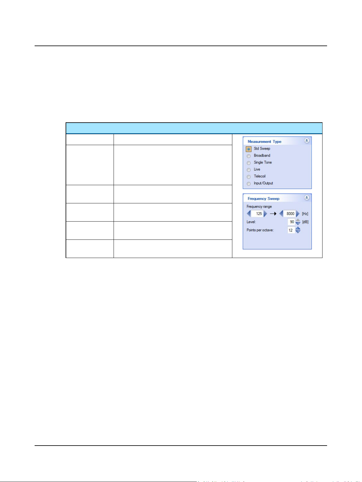
You define the tests by clicking your selections in the Control Panel. You will find additional settings available in the
Options dialog, when you select Tools > Options.
When you click on a selection in the Measurement Type part of the Control Panel, the related settings are shown in the
panel just below.
Control Panel settings
Std Sweep
Broadband
Single Tone
Live
Telecoil
Input/Output
A frequency sweep within the range defined.
Pre-recorded signals that can be selected from an
extensive sound library. With broadband signals you
have the option of using front or back speaker. You
can also set the duration of the signal, which is useful
when measuring dynamic signals such as speech.
Measuring single tones is particularly useful to establish the harmonic distortion of the tested device.
Measures without any signal. Useful for measuring susceptibility for background noise.
Presents a frequency sweep within the range defined.
The stimulus level is defined as mA/m.
Presents the single tone at several levels and measures the output as a function of each input level.
Combining sequences
If you have measured a sequence, you can load another sequence to add to the first one.
Showing/hiding curves
You can hide a measured curve by deselecting the check box in the Curve legend in the measurement table.
Gain axis
You can display the measurement gain by clicking the Gain check box in the measurement table.
The gain is calculated as the difference between the coupler microphone and the reference microphone in the test chamber.
Otometrics - AURICALHIT
31
Page 32

5 Cleaning, Repair and Calibration
5 Cleaning, Repair and Calibration
Warning • Under no circumstances disassemble AURICALHIT. Contact your supplier. Parts inside AURICALHIT
must only be checked or serviced by authorized personnel.
Calibration
Calibration of the coupler microphone, and calibration of a new reference or coupler microphone must only be performed
by authorized personnel.
Maintenance
AURICALHIT requires no preventive maintenance except for cleaning and regular calibration of the reference microphone.
Repair
For any type of repair, please contact your supplier.
• Reference microphone
The reference microphone can be replaced. The procedure is described in Replacing/updating the reference micro-
phone ► 33. Replacement of the reference microphone should only be performed by authorized service personnel.
• Test chamber foam lining
AURICALHIT is lined with sound absorbing foam. The foam in the base area of the test chamber can be replaced. See
Replacing floor lining ► 33. Replacement of the foam lining should only be performed by authorized service per-
sonnel.
Calibration
The reference microphone should be calibrated regularly. See Calibrating the reference microphone ► 15.
If a new coupler microphone has been taken into use, see Calibrating the coupler microphone ► 36.
5.1 Cleaning
There are no specific requirements to sterilization or disinfection of the device.
5.1.1 Cleaning the device
Make sure that the device is kept clean and free of dust:
• Remove dust using a soft brush.
• To clean the cabinet, use a soft, slightly damp cloth with a small amount of mild detergent on it.
Keep the unit away from liquids. Do not allow moisture inside the unit. Moisture inside the unit can damage the instru-
ment and it may result in a risk of electrical shock to the user or patient.
5.1.2 Cleaning accessories
Adapters
If needed, remove any acoustic putty residue, and use an alcohol based wipe to clean the adapter.
32 Otometrics - AURICALHIT
Page 33
5.2 Service and repair
It is recommended that you keep the packing material in which AURICALHIT was delivered. If you need to send it in for
service, the original packing material will ensure protection against damage during transport, etc.
For the sake of safety and in order not to void the warranty, service and repair of electro-medical equipment should be carried out only by the equipment manufacturer or by service personnel at authorized workshops. In case of any defects,
make a detailed description of the defect(s) and contact your supplier. Do not use a defective device.
5.2.1 Replacing/updating the reference microphone
This task must be performed by a qualified service technician.
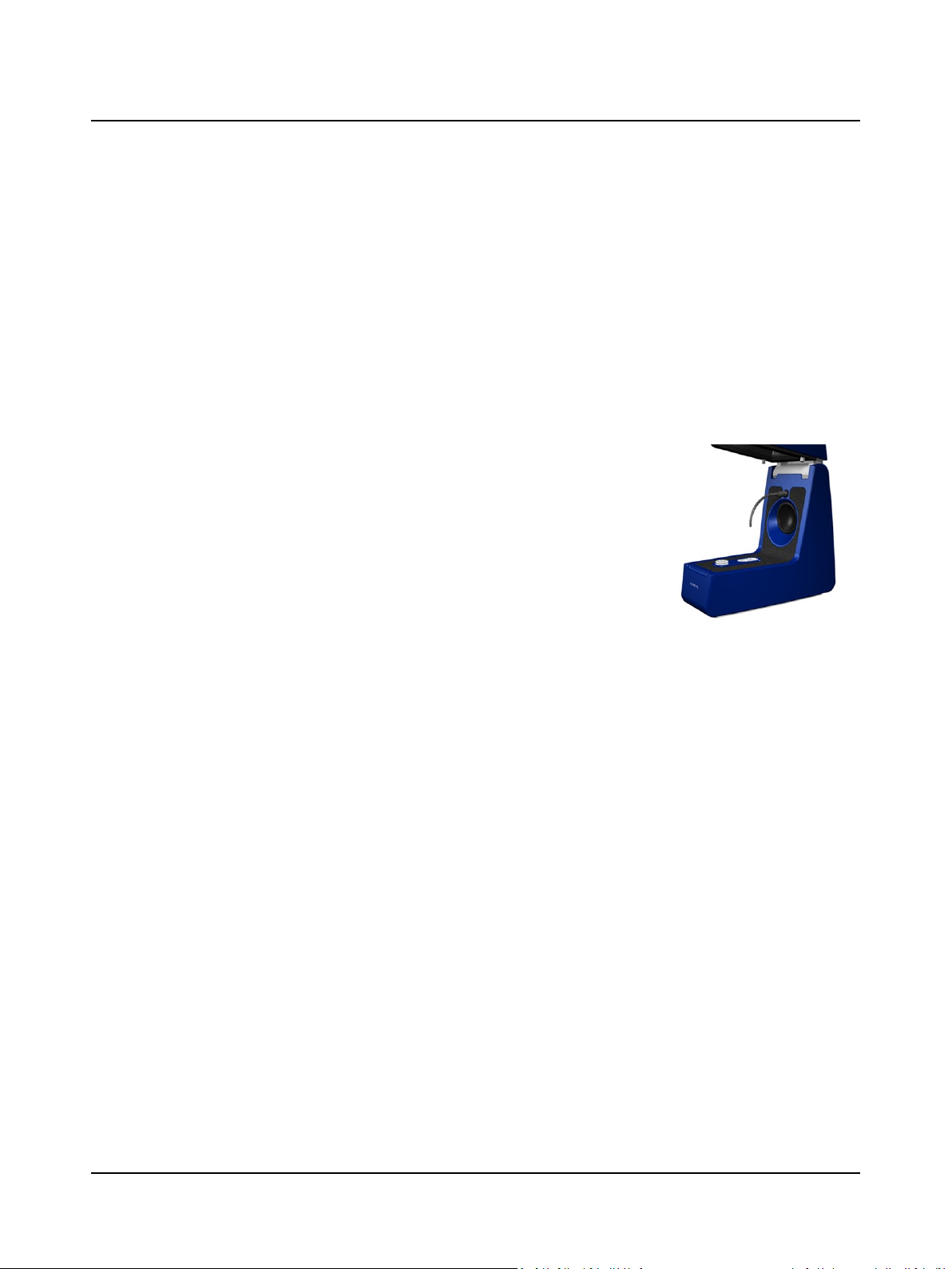
1. Gently remove the reference microphone by pulling it carefully out of its socket.
1. Gently remove the reference microphone by pulling it carefully out of its socket.
2. Insert the new reference microphone in the socket.
3. Launch OTOsuite and select the HIT module in the Navigation panel.
4. Select Tools > AURICALHIT Calibration > More > New Reference Microphone.
5. Browse to select the calibration file supplied with the new reference microphone.
Make sure that the listed microphone serial number matches the serial number of
the file.
6. Load the file.
7. Calibrate the reference microphone with the coupler microphone. See Calibrating
the reference microphone ► 15.
5 Cleaning, Repair and Calibration
5.2.2 Replacing/updating the coupler microphone
This task must be performed by a qualified service technician.
1. Place the new coupler microphone in the high position.
2. Insert the new reference microphone in the socket.
3. Launch OTOsuite and select the HIT module in the Navigation panel.
4. Select Tools > AURICALHIT Calibration > More > New Coupler Microphone.
5. Browse to select the calibration file supplied with the new coupler microphone. Make sure that the listed microphone serial number matches the serial number of the file.
6. Load the file.
7. Calibrate the coupler microphone using a 94 dB calibrator. See Calibrating the coupler microphone ► 36.
5.2.3 Replacing floor lining
Remove the old floor lining from the base area, and place a new lining in the same position.
Otometrics - AURICALHIT
33
Page 34

5 Cleaning, Repair and Calibration
5.3 Calibration
5.3.1 How often is calibration necessary?
Otometrics recommends that you set up a schedule for fully testing and calibrating the AURICALHIT microphones at regular intervals. This will help meet standards, and will ensure continued reliability and accuracy.
Reference microphone
Otometrics recommends that you calibrate the reference microphone daily or weekly. Set up the interval to suit your purposes. See Calibrating the reference microphone ► 15.
Coupler microphone
Otometrics recommends that a qualified service technician calibrates and validates the coupler microphone at least once a
year. See Calibrating the coupler microphone. OTOsuite will prompt you with an indication of when the calibration
expires.
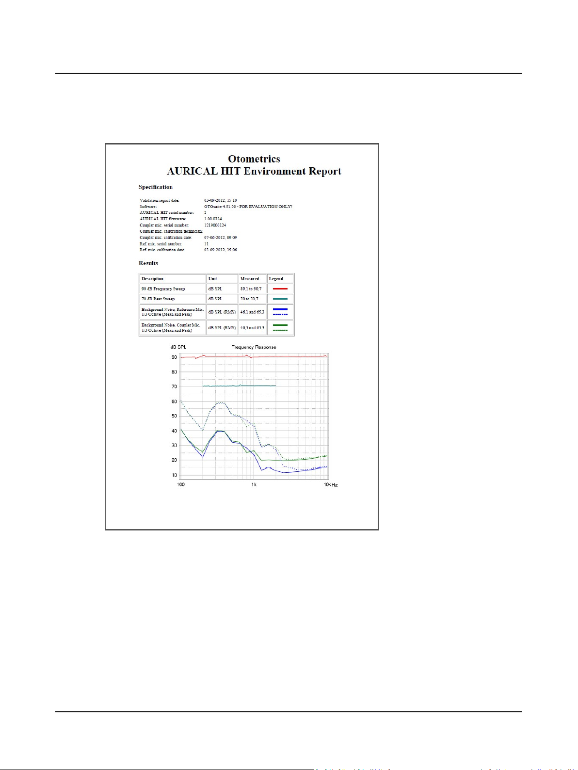
5.3.2 Environment Report
The Environment Report is a troubleshooting/system self-test tool, which can be used for verifying that the microphones,
loudspeakers, internal electronics and the acoustic chamber are functioning properly.
Note•Make sure that you follow the on-screen instructions carefully to obtain correct results.
The tool executes the following measurements in an automatic sequence:
• 90 dB front speaker frequency sweep
• 70 dB back speaker frequency sweep
• Background noise
Both reference microphone and coupler microphone are used in each of these measurements, and the results are compared between them.
Procedure
1. Make sure that the test environment is as silent as possible.
2. Place the coupler in the high position.
3. Position the reference microphone (1) pointing straight down from above and
centered 1-2 millimeters above the coupler measurement microphone (3).
34 Otometrics - AURICALHIT
Page 35
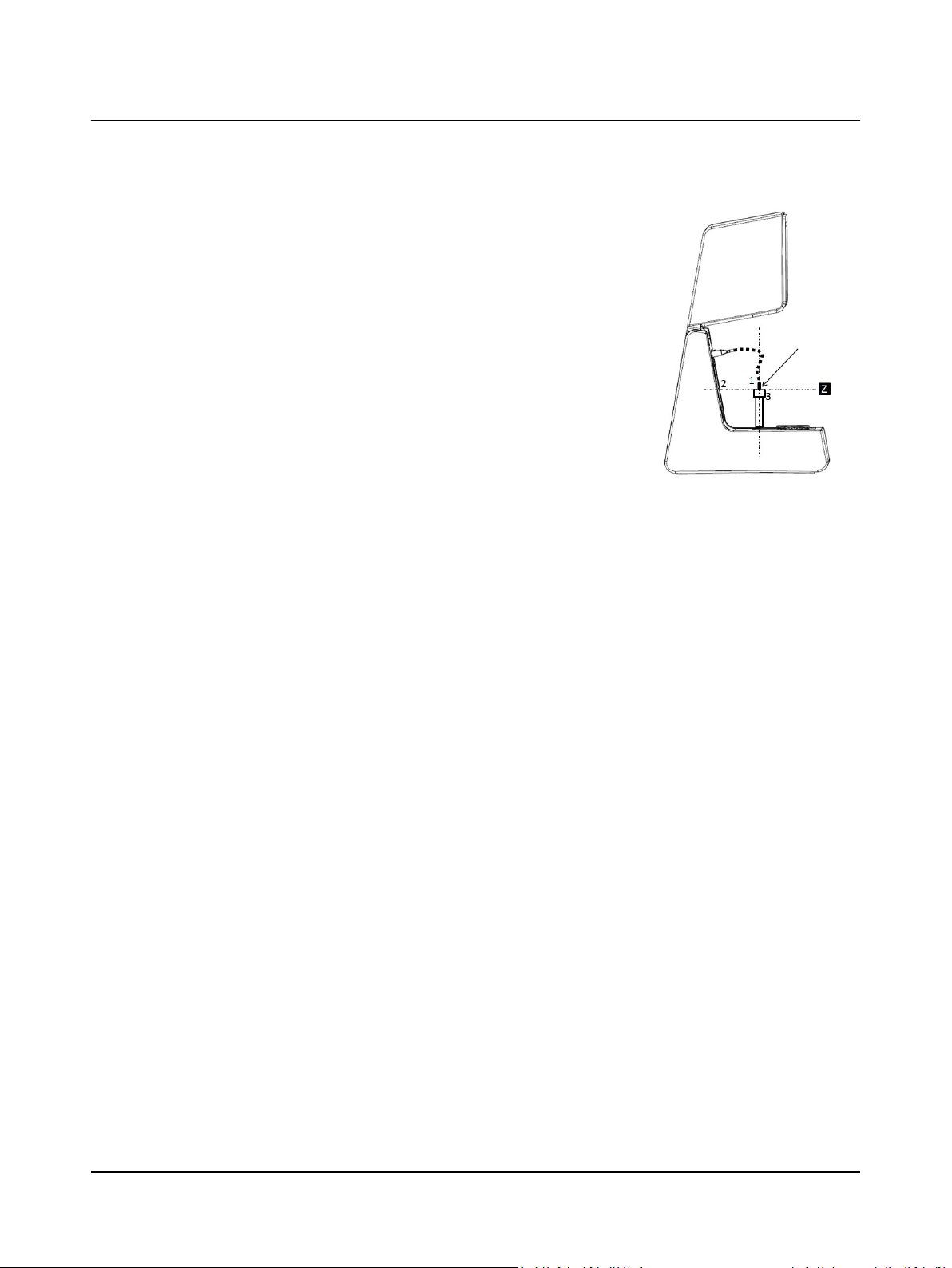
4. The microphones must have the exact same distance to the main loudspeaker
(2), along the Z axis. You can ensure this by looking at the test chamber from the
side when you adjust the reference microphone position for validation.
5. Close the lid.
6. Select Tools > AURICALHIT Calibration > More > Environment Report.
7. Click Start. The test lasts less than 1 minute.
5 Cleaning, Repair and Calibration
Otometrics - AURICALHIT
35
Page 36
5 Cleaning, Repair and Calibration
The report
5.3.3 Calibrating the coupler microphone
Coupler microphone calibration must be performed by a certified service technician.
What you need to calibrate
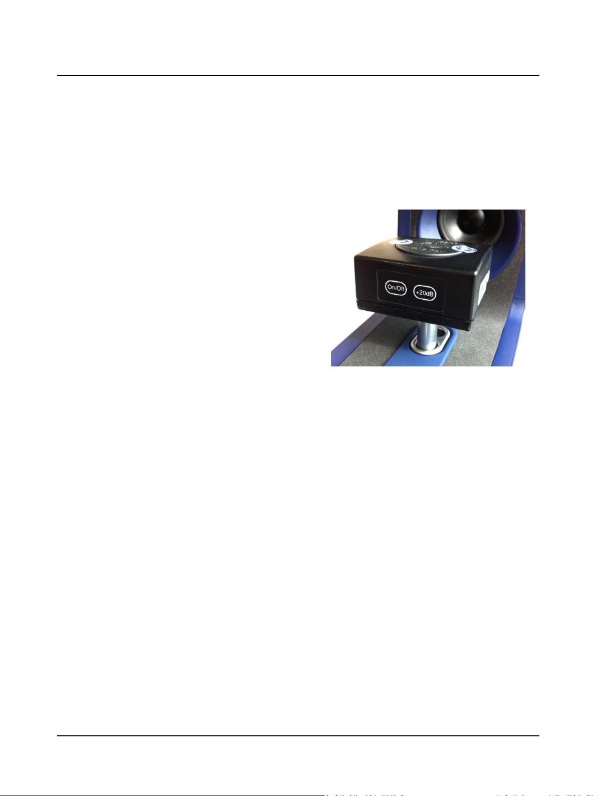
• 94 dB sound level calibrator
• ½ in microphone adapter
36 Otometrics - AURICALHIT
Page 37
The procedure
1. Launch OTOsuite and select the HIT module in the Nav-
igation panel.
2. Select Tools > AURICALHIT Calibration > More >
Coupler Microphone.
3. Screw the ½ in microphone adapter onto the coupler
microphone.
4. Place the sound level calibrator on the coupler microphone and place it in the high position in the test chamber.
5. Switch on the calibrator.
6. Close the lid.
7. Click Start.
8. Follow the on-screen instructions carefully.
9. When you have calibrated the coupler microphone, you
should calibrate the reference microphone. See Cal-
ibrating the reference microphone ► 15.
5 Cleaning, Repair and Calibration
5.4 The battery simulator
A 1/8” stereo jack supplies direct current from AURICALHIT to a battery which is inserted into the battery compartment
of the hearing instrument during testing.
The voltage and source impedance of the battery simulator are controlled by the test software and the current can be
measured by the simulator and the software.
Five different battery pills are available as optional accessories (see Accessories ► 43 for details).
Voltage range 0 to 3.5 V
Current range 0 to 50 mA
Source impedance range
Tip Battery supply
Ring Sense voltage
Shield Ground
0 to 25.5 Ω.
Otometrics - AURICALHIT
37
Page 38

6 Troubleshooting
6 Troubleshooting
Problem Action
Active screen disappears
Test results
seem incorrect
Too much ambient noise
• If your active screen becomes hidden, move the top screen(s) until you can click on your active
screen to bring it to the front of your desktop.
If your test results seem to be incorrect, do the following:
1. Open AURICALHIT and remove the hearing instrument and the coupler microphone.
2. Point the reference microphone towards the area of the coupler microphone socket in
AURICALHIT.
3. Close the lid.
4. Run the test.
5. Look at the curve at 90dBSLP. It must be as flat as possible.
6. If it is not, make a Validation Report, recalibrate, and repeat the sequence above.
7. If test results still seem incorrect, replace the relevant microphone and calibrate the new
microphone.
In order to exclude ambient noise and to comply with the ANSI S3.22 standard, place the system in
a moderately quiet room.
• If noise enters the test chamber, try moving the device a little, as this can cause big changes in
the noise level of certain frequencies.
• If noise enters the test chamber via the table or stand, try adding a heavy-duty mounting mat
or replace the table or stand with a more suitable support.
• If needed, place the PC and any other equipment on a separate table to prevent noise and
vibrations from influencing sensitive tests.
38 Otometrics - AURICALHIT
Page 39
7 Standards and Safety
This manual contains information and warnings, which must be followed to ensure the safe performance of the devices and
software covered by this manual. Local government rules and regulations, if applicable, should also be followed at all times.
7.1 AURICALHIT
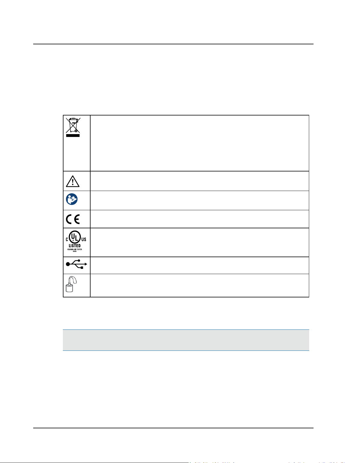
Electronic equipment covered by the Directive 2002/96/EC on waste electrical and electronic equipment
(WEEE).
All electrical and electronic products, batteries, and accumulators must be taken to separate collection at
the end of their working life. This requirement applies in the European Union. Do not dispose of these
products as unsorted municipal waste.
You can return your device and accessories to Otometrics, or to any Otometrics supplier. You can also contact your local authorities for advice on disposal.
Consult user manual for warnings and cautions.
Consult instructions for use.
7 Standards and Safety
Complies with Medical Devices Directive 93/42/EEC and RoHS Directive (2011/65/EC).
UL listing mark.
USB socket for connecting AURICALHIT to a computer.
Socket for connecting external coupler microphone.
7.2 Warning notes
Warning • For warning notes applying to AURICALHIT when in use with AURICAL FreeFit, see the warning notes
in the AURICAL FreeFit Safety section in the AURICAL FreeFit documentation.
1. The device is intended for testing purposes by audiologists, hearing instrument dispensers, and other health care professionals in testing programmable hearing instruments.
2. Accidental damage and incorrect handling can have a negative effect on the functionality of the device. Contact your
supplier for advice.
Otometrics - AURICALHIT
39
Page 40

7 Standards and Safety
3. For the sake of safety and in order not to void the warranty, service and repair of electro-medical equipment should
be carried out only by the equipment manufacturer or by service personnel at authorized workshops. In case of any
defects, make a detailed description of the defect(s) and contact your supplier. Do not use a defective device.
4. It is recommended to install the unit in an environment that minimizes the amount of environmental noise.
5. It is recommended to install the unit in an environment that minimizes the amount of static electricity. For example,
anti-static carpeting is recommended.
6. Do not store or operate the device at temperatures and humidity exceeding those stated in the Technical Specifications, Transport and storage.
7. Keep the unit away from liquids. Do not allow moisture inside the unit. Moisture inside the unit can damage the
instrument and it may result in a risk of electrical shock to the user or patient.
8. Do not use the instrument in the presence of flammable agents (gases) or in an oxygen-rich environment.
9. No parts may be eaten, burnt, or in any way used for purposes other than the applications defined in the Intended Use
section of this manual.
10. The device should be turned off before any connections are established. To disconnect the device from the power
supply, pull the USB plug out of the PC, or shut down the PC.
11. We recommend that an annual calibration be performed on accessories containing microphones. Furthermore, we
recommend that calibration be performed if the equipment has suffered any potential damage (e.g. microphone
dropped on the floor). Note that calibration has been performed only on the microphones supplied! If you wish to use
other microphones for testing with the device, please contact your local distributor first.
12. To prevent cross-infection, use fresh acoustic putty when you test the next hearing instrument.
13. For safety reasons and due to effects on EMC, accessories connected to the equipment's outlet fittings must be
identical to the type supplied with the system.
14. Unwanted noise may occur if the device is exposed to a strong radio field. Such noise may interfere with the process
of testing or fitting a hearing instrument. Many types of electrical devices, e.g. mobile telephones, may generate radio
fields. We recommend that the use of such devices in the vicinity of the device is restricted as much as possible. Likewise, we recommend that the device is not used in the vicinity of devices sensitive to electromagnetic fields.
15. Changes or modifications not expressly approved by the manufacturer could void the user's authority to operate the
equipment.
16. The device can be disposed of as normal electronic waste, according to local regulations.
17. Use only the power supply specified in Technical Specifications, Technical specifications ► 42.
When assembling a system, the person carrying out the assembly must take into account that other connected equipment which does not comply with the same safety requirements as this product (e.g. PC
and/or printer) may lead to a reduction in the overall safety level of the system. The equipment must comply with IEC 60950.
7.3 The OTOsuite HIT Module
Complies with Medical Devices Directive 93/42/EEC and RoHS Directive (2011/65/EC).
40 Otometrics - AURICALHIT
Page 41

Used in error message dialogs if software program fails. See the detailed information in the dialog box.
7.4 Manufacturer
GNOtometricsA/S
Hoerskaetten 9, 2630 Taastrup
Denmark
( +45 45 75 55 55
7 +45 45 75 55 59
www.otometrics.com
7.4.1 Responsibility of the manufacturer
The manufacturer is to be considered responsible for effects on safety, reliability, and performance of the equipment only
if:
• All assembly operations, extensions, re-adjustments, modifications or repairs are carried out by the equipment manufacturer or personnel authorized by the manufacturer.
• The electrical installation to which the equipment is connected complies with EN/IEC requirements.
• The equipment is used in accordance with the instructions for use.
The manufacturer reserves the right to disclaim all responsibility for the operating safety, reliability and performance of
equipment serviced or repaired by other parties.
7 Standards and Safety
Otometrics - AURICALHIT
41
Page 42

8 Technical specifications
8 Technical specifications
Type identification
AURICALHIT is type 1082 from GNOtometricsA/S.
Acoustic stimulus generation
In closed test chamber
Frequency response, re. 1 kHz, main loudspeaker (equalized)
Frequency response, re. 1 kHz, rear loudspeaker (equalized)
Maximum output level, main loudspeaker 90 dB SPL (pure tone), 78 dB SPL (speech)
Harmonic distortion, acoustic tone output, main loudspeaker
125 to 200 Hz: ± 3.0 dB
200 to 2000 Hz: ± 1.5 dB
2000 to 5000 Hz: ± 2.5 dB
5000 to 10000 Hz: ± 3.0 dB
125 to 10000 Hz: ± 3.0 dB
Less than 0.5 % up to 70 dB SPL, Less than 2.0 %, 70-90 dB SPL
Acoustic measurements
Frequency range, coupler microphone
(equalized)
125 to 200 Hz: ± 3 dB
200 to 5000 Hz: ± 1 dB
5000 to 10000 Hz: ± 3 dB
Battery simulator
Voltage range 0 to 2.0 V
Resolution, voltage 0.02 V
Accuracy, voltage ± 0.05 V
Output impedance range 3 to 10 ohm
Resolution, impedance 0.1 ohm
Accuracy, impedance ± 5 %
Current measurement range 0.5 to 40 mA
Current measurement accuracy ± 5 %
Tele coil
Max. field strength 31.6 mA/m
USB port connector
Type: USB device port, type B
Interface: USB 2.0
42 Otometrics - AURICALHIT
Page 43

8 Technical specifications
Speed: High speed
Power consumption: Max. 2.5 W
Dimensions
Approximately, WxDxH 16 x 31 x 28 cm (6.3 x 12.2 x 11 in)
Weight
Weight 6.3 kg (13.9 lb)
Transport and storage
Temperature: -15ºC to +55ºC (5ºF to 131ºF)
Air humidity: 10% to 90%, non-condensing
Operating environment
Operating environment Indoors
Operating temperature range 15 to 35 ºC (59 to 95 ºF)
Maximum relative humidity Maximum relative humidity 80% for temperatures up to 31ºC (88 ºF) decreas-
ing linearly to 50% relative humidity at 40ºC (104 ºF).
Altitude Up to 2,000 m (6,562 feet)
Warm-up time < 15 min
Standards
AURICALHIT CE-marked according to the Electrical Safety Directive IEC 61010-1
Test standards ANSI S3.22
IEC 60118-7
EMC IEC 61326-1
Accessories
• BTE adapter tube
• Coupler set, including 2cc coupler, and snap-on adapters HA-1 (ITE), HA-2 (BTE), and body-worn
• Elevation plate
• Reference microphone
• Coupler microphone
• Accessory Box
• Battery Probe Kit
• Accessory Box microphone cable
• USB cable
Otometrics - AURICALHIT
43
Page 44

8 Technical specifications
• Acoustic putty
• Ear simulator
• AURICALHIT Reference Manual
• AURICALHIT User Guide
44 Otometrics - AURICALHIT
Page 45

Index
Index
A
Accessories
cleaning 32
list 43
Accessory Box
description 14
Acoustic measurements 42
Acoustic stimulus generation 42
Adapters 19
Ambient noise
troubleshooting 38
AURICAL HIT
accessories 43
cleaning 32
connecting 7
dimensions 43
general description 7
installation 7
maintenance 32
operating conditions 43
repair 33
replace foam lining 33
safety 39
standards 39, 43
technical specifications 42
test chamber 7
transport and storage 43
weight 43
B
Battery simulator 18, 42
description 11
details 37
Bluetooth
testing 24
Body-worn
adapter 19
hearing instruments
testing 26
BTE
adapter tube description 9
testing hearing instruments 20
testing with adapter tube 20
C
Cable groove
description 11
Calibration 34
coupler microphone 36
how often 34
initial calibration 7
reference microphone 15
Cleaning 32
accessories 32
device 32
Connecting
AURICAL HIT 7
Coupler adapters 19
Coupler assembly 9
Coupler microphone
calibration 36
replacement 33
sockets 12
Coupler microphone sockets 12
Coupler type 9
D
Description
Accessory Box 14
AURICAL HIT lid 12
Battery simulator 11
BTE adapter tube 9
cable groove 11
coupler assembly 9
coupler microphone sockets 12
elevation plate 11
induction loops 12
main loudspeaker 12
rear loudspeaker 12
reference microphone 9
sound absorbing lining 12
test chamber 7
Dimensions 43
Directionality
introduction 5
testing 27
Otometrics - AURICALHIT
45
Page 46

Index
E
Elevation plate
description 11
Environmental noise
troubleshooting 38
F
FM
advantage 24
testing 24
transparency 24
FM testing
elevation plate description 11
Foam lining
replacement 33
H
HA-1 19
testing ITE hearing
instruments 22
testing thin-tube hearing instru-
ments 21
HA-2 19
testing BTE 20
Hearing instruments
adapters 19
battery simulator 18
Bluetooth testing 24
body-worn testing 26
BTE testing 20
directionality testing 27
FM testing 24
FreeStyle test 29
introduction 5
ITE testing 22
positioning 16
standard test 26
telecoil testing 24
testing 15
testing in OTOsuite HIT 26
testing wireless
transmitters 24
thin-tube testing 21
thin-tube testing with HA-1
adapter 21
HIT module
testing 26
I
Induction loops
description 12
Initial calibration 7
Installation 7
initial calibration 7
Intended use 5
required user qualifications 5
Introduction 5
ITE hearing instruments
testing 22
L
Lid
description 12
Loudspeaker
description 12
rear, description 12
M
Main loudspeaker
description 12
Maintenance 32
Manufacturer 41
Microphone
calibrate coupler
microphone 36
calibrate reference
microphone 15
positioning reference micro-
phone 17
replace coupler microphone 33
replace reference
microphone 33
N
NOAH
integration 5
46 Otometrics - AURICALHIT
Page 47

Index
Noise
troubleshooting too much
noise 38
O
Operating conditions 43
OTOsuite HIT
testing 26
P
Positioning
general guidelines 16
hearing instruments 16
reference microphone 17
R
Rear loudspeaker
description 12
RECD
introduction 5
Reference microphone
calibration 15
description 9
positioning 17
replacement 33
Repair 33
Replacement
coupler microphone 33
foam lining 33
reference microphone 33
S
Safety
AURICAL HIT 39
AURICAL HIT warning notes 39
Screen
disappears, troubleshooting 38
Sound absorbing lining
description 12
Standard test 26, 29
Standards 43
AURICAL HIT 39
Storage 43
T
Technical specifications 42
accessories 43
acoustic measurements 42
acoustic stimulus
generation 42
battery simulator 42
dimensions 43
operating conditions 43
standards 43
telecoil 42
transport and storage 43
USB connection 42
weight 43
Telecoil
specifications 42
telecoils in AURICAL HIT 12
testing 24
Test chamber
Accessory Box 14
battery simulator 11
cable groove 11
coupler assembly 9
coupler microphone sockets 12
description 7
elevation plate 11
induction loops 12
lid 12
main loudspeaker 12
rear loudspeaker 12
reference microphone 9
sound absorbing lining 12
Testing
adapters 19
battery simulator 18
Bluetooth 24
body-worn hearing
instruments 26
BTE hearing instruments 20
directionality 27
FM 24
FreeStyle test 29
guidelines 15
hearing instruments 15
Otometrics - AURICALHIT
47
Page 48

Index
incorrect test results,
troubleshooting 38
ITE hearing instruments 22
main tasks 15
OTOsuite HIT 26
positioning hearing
instruments 16
positioning reference micro-
phone 17
standard test 26
telecoil 24
thin-tube hearing
instruments 21
thin-tube hearing instruments
with HA-1 adapter 21
wireless transmitters 24
with BTE adapter tube 20
Thin-tube hearing instruments
testing 21
testing with HA-1 adapter 21
Thin tube adapter 19
Transport and storage 43
Troubleshooting 38
active screen disappears 38
ambient noise 38
incorrect test results 38
U
USB
specifications 42
W
Warning notes
AURICAL HIT 39
Weight 43
Wireless transmitters
testing 24
48 Otometrics - AURICALHIT
 Loading...