

Page 1

AURICALAud
Reference Manual
Doc. No.7-50-1030-EN/15
Part No.7-50-10300-EN
Page 2

Copyrightnotice
© 2011,2017GNOtometricsA/S. Allrights reserved. ® Otometrics, the OtometricsIcon,AURICAL, MADSEN, ICSand HORTMANN
are registered trademarks of GNOtometricsA/S in the U.S.A.and/or other countries.
Version release date
2017-03-13 (153515)
Technical support
Please contactyour supplier.
2
Otometrics - AURICAL Aud
Page 3

Table of Contents
1 Introduction to AURICAL Aud 7
1.1 AURICAL Aud 7
1.2 HI-PRO2 8
1.3 AURICAL speaker unit 8
1.4 The OTOsuite Audiometry Module 8
1.4.1 NOAH 9
1.5 Intended use 9
1.6 About this manual 10
1.6.1 Installation and assembly 10
1.6.2 Safety 10
1.6.3 Training 10
1.7 Typographical conventions 10
1.7.1 Navigation 11
2 Navigating in the OTOsuite Audiometry Module 13
2.1 The Audiometry Module main window 13
2.2 Menus and toolbar icons 13
2.2.1 File menu 14
2.2.2 Edit menu 14
2.2.3 View menu 14
2.2.4 Measurement menu 15
2.2.5 Tools menu 16
2.3 The Patient Responder indicator 16
2.4 The Masking Assistant 17
2.5 The Control Panels 19
2.5.1 Quick Select - Tone 20
2.5.2 Quick Select - Speech 21
2.5.3 Test Options 22
2.5.4 Monitor and Level 24
2.6 The stimulus bar 25
2.6.1 Test controls 25
2.6.2 The Tone stimulus bar 26
2.6.3 The Speech stimulus bar 27
2.7 The Tone test screen 27
2.7.1 The work area in the Tone screen 28
2.7.2 The audiogram 28
2.7.3 Curves and symbols selection 30
2.7.3.1 Selecting a symbol or curve 30
2.7.3.2 Creating new symbols 31
2.7.4 Compare audiograms 32
2.7.5 Tone feature boxes 32
2.7.6 Tone editing options 34
2.8 Work-flow related features 35
2.8.1 Selecting orientation 35
2.8.2 Automatic frequency/level shift when storing 35
2.8.3 Stimulus duration 36
2.8.4 Ear shift frequency and level setting 36
2.8.5 Saving non-stimulus channel as masking 36
2.9 The Speech test screen 36
Otometrics - AURICAL Aud
3
Page 4

2.9.1 Selecting word or phoneme scoring 37
2.9.2 Selecting speech material 41
2.9.3 Scoring words using integrated OTOsuite Speech Material 43
2.9.4 Scoring words using external sound source 45
2.9.5 Scoring phonemes using integrated OTOsuite speech material 46
2.9.6 Scoring phonemes using external sound source 47
2.9.7 Saving source levels for speech material 48
2.10 Speech testing - tabular view 49
2.10.1 Creating and editing the speech test table 50
2.10.2 Speech editing options - tabular view 51
2.10.3 Storing SNR for Speech testing 52
2.11 Speech testing - graph view 52
2.11.1 Speech editing options - graph view 54
2.12 Speech feature boxes 55
2.13 Terms and abbreviations used in Speech testing 55
2.14 Special tests 57
2.14.1 SISI (Short Increment Sensitivity Index) 57
2.14.1.1 Navigating in SISI 57
2.14.1.2 The test process - SISI 60
2.14.2 ABLB (Alternate Binaural Loudness Balance) 60
2.14.2.1 Navigating in ABLB 60
2.14.2.2 The test process 63
2.14.3 TEN (Threshold-Equalizing Noise) 63
2.14.4 Ambient Noise Assessor 64
2.14.4.1 Selecting the FreeFit device in OTOsuite 64
2.14.4.2 Measuring Ambient Noise with AURICALFreeFit 64
2.14.4.3 Noise level indicators stored with measurements 67
2.14.4.4 Activating the Ambient Noise Assessor automatically 68
2.14.4.5 Minimum HTL per transducer type 69
2.15 Test controls (keyboard, mouse) 69
2.15.1 PC keyboard controls 69
3 Preparing for testing 71
3.1 Preparing the test environment 71
3.2 Preparing the test equipment 71
3.3 Listening check 72
3.4 Preparing the client 72
3.4.1 Hygienic precautions 72
3.4.2 Inspecting the client’s ear(s) 72
3.5 Proper transducer placement 72
4 Examples of audiometric testing 75
4.1 Testing the older child or adult patient 75
4.1.1 Assessing pure tone threshold using the Hughson/Westlake procedure 75
4.1.2 Assessing pure tone or speech most comfortable loudness level (MCL) 76
4.1.3 Assessing pure tone or speech uncomfortable loudness level (UCL) 76
4.1.4 Assessing speech reception threshold (SRT) using the Hughson/Westlake procedure 77
4.1.5 Assessing word recognition score 77
4.2 Special Tests 78
4.2.1 Performing Tone Decay using the Modified Carhart Method 78
4.2.2 Performing a pure tone Stenger 79
4.2.3 Performing speech Stenger 79
4.2.4 Performing Weber 80
4 Otometrics - AURICAL Aud
Page 5

4.2.5 Performing Rinne 80
4.2.6 Performing Alternate Binaural Loudness Balancing (ABLB) test 81
4.2.7 Performing Short Increment Sensitivity Index (SISI) test 81
4.3 Testing with sound files 82
4.3.1 Playing sound files without word lists 82
4.3.2 Playing sound files with word lists 82
4.4 Performing sound-field speech audiometry off site 83
4.4.1 Enabling portable sound-field audiometry 83
4.4.2 Performing a manual calibration of AURICAL Aud speakers 83
4.4.3 Using manual speaker calibration values 84
5 Unpacking and Installing 85
5.1 Requirements to the location 85
5.1.1 Requirements to noise in the test environment 85
5.2 Unpacking 86
5.3 Storing 86
5.4 Views of AURICAL Aud 86
5.4.1 AURICAL Aud 86
5.4.2 AURICAL Aud - with HI-PRO2 87
5.4.3 AURICAL speaker unit 88
5.5 Connection panels 88
5.5.1 AURICALAud connection panel 88
5.5.2 Built-in HI-PRO2 connection panel 92
5.5.3 AURICAL speaker unit connection panel 92
5.6 Assembling AURICAL Aud 93
5.7 Desktop or wall installation 94
5.7.1 Connecting accessories and PC to AURICAL Aud 95
5.7.2 Mounting AURICAL Aud on the mounting plate 95
5.8 AURICAL speaker unit installation 95
5.8.1 Connecting cables to the AURICAL speaker unit 96
5.8.2 Connecting accessories and PC to AURICAL Aud 98
5.8.3 Mounting AURICAL Aud on the AURICAL speaker unit 99
5.9 Powering AURICAL Aud 99
6 Configuring the Audiometry Module 101
7 Communicating with the device 103
7.1 Reconnecting to the device 103
7.2 Updating device firmware 103
8 AURICAL Aud with HI-PRO2 105
9 Tuning the AURICAL Aud speaker for use with third-party applications 106
9.1 Microphone placement for use with RoomTune 106
9.2 Preparing to use RoomTune 106
9.3 Using RoomTune in a new environment 107
9.4 Using RoomTune to keep AURICAL Aud speakers in tune 108
9.5 Cancelling faulty RoomTune data 109
9.6 Using RoomTune to measure sound levels 109
9.7 Exiting RoomTune 110
10 Maintenance and calibration 111
10.1 Service and repair 111
Otometrics - AURICAL Aud
5
Page 6

10.1.1 Fuses 111
10.2 Maintenance 111
10.3 Cleaning 111
10.4 Calibration 112
11 Troubleshooting 113
11.1 Powering 113
11.2 Software/device communication 113
11.3 HI-PRO2 113
12 Standards and Safety 115
12.1 AURICALAud 115
12.2 Warning notes 115
12.2.1 Connector warning notes 115
12.2.2 General warning notes 116
12.3 The OTOsuite Audiometry Module 118
12.4 Manufacturer 118
12.4.1 Responsibility of the manufacturer 118
13 Technical specifications 119
13.1 AURICAL Aud 119
13.2 HI-PRO2 (built-in) 127
13.3 AURICAL speaker unit 128
13.4 Accessories 128
13.5 Notes on EMC (Electromagnetic Compatibility) 129
Index 133
6 Otometrics - AURICAL Aud
Page 7
1 Introduction to AURICAL Aud
1.1 AURICAL Aud
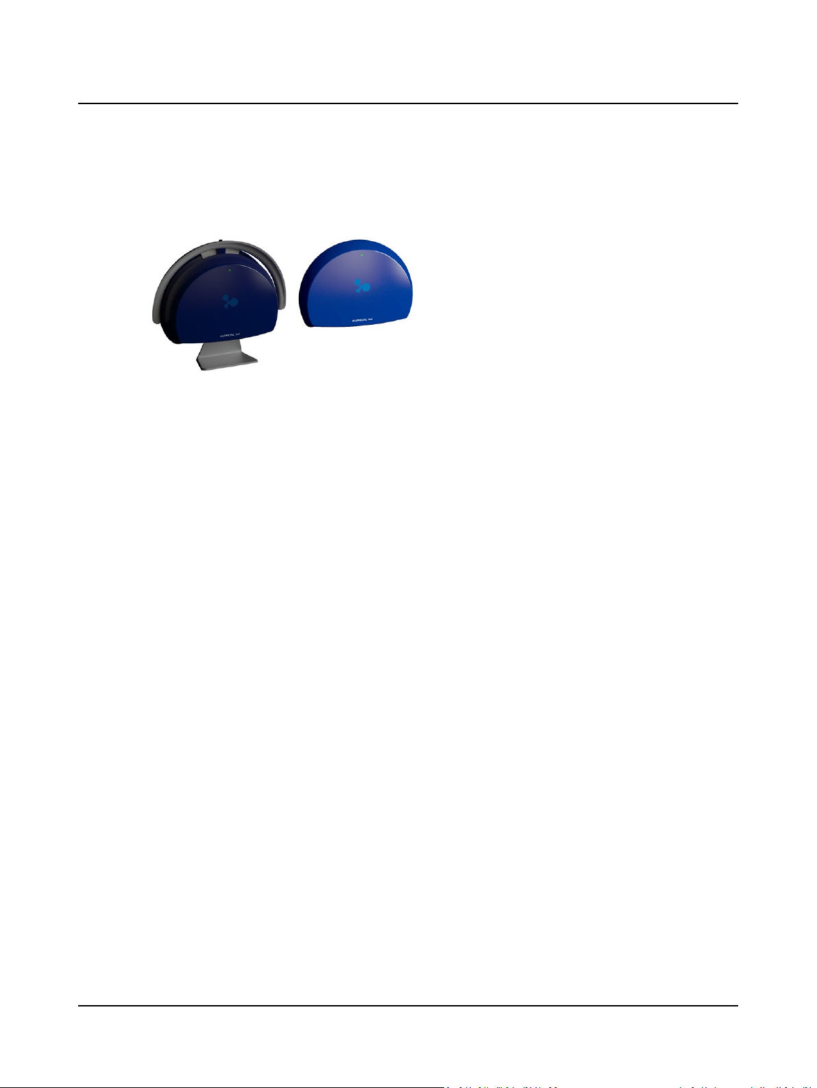
AURICAL Aud is a PC-controlled audiometer for testing a
person's hearing. The audiometer, which is connected to a
PC via USB, is operated from the OTOsuite Audiometry
Module PC software.
With AURICAL Aud you can perform all standard audiometric tests, tone and speech audiometry and special
tests.
The intuitive graphical user interface and the user test feature enable you to carry out your tests with very little
effort.
You can connect other devices easily through the built-in USB Hub, and AURICAL Aud provides the necessary connections
to carry out counseling using the OTOsuite Counseling and Simulations module.
Configurations
AURICAL Aud is available as:
• part of the integrated AURICAL system
• a separate audiometer
Each configuration is available with an optional built-in HI-PRO2 and an optional AURICAL speaker unit. AURICAL Aud can
be placed on the desk top, mounted directly on the back of the AURICAL speaker, or, if the optional kit is used, it can be
mounted on the wall or under the desk.
Operating AURICAL Aud
• You operate AURICAL Aud from the PC’s keyboard/mouse with the OTOsuite Audiometry Software Module acting as
the display showing the intensity, frequency as well as current settings and other information on the PC monitor.
• From the OTOsuite Audiometry Software Module, which is NOAH compatible, you can monitor test results, create
User Tests, store and export data, and print reports.
Test intensities and frequencies as well as the current test settings and other information are shown on the PC monitor.
• Speech input signals can be taken from audio files on the PC hard drive, CD-ROM, external line-in devices such as a CD
player, or live-voice from a microphone.
Outputs
AURICAL Aud supports the following types of output:
• One set of headphones. The supported headphone types are:
– TDH39 headphones
– TDH39 with ME70
– Holmco
– HDA 200/HDA300
• Insert phones
• Bone oscillator
Otometrics - AURICAL Aud
7
Page 8

1 Introduction to AURICAL Aud
• 2 sound field speakers. The speakers can use either the power amplifier built into AURICAL Aud or an external power
amplifier.
Note•Sound-field testing is not available on some models.
1.2 HI-PRO2
AURICAL Aud is available with an optional built-in HI-PRO2 (Hearing Instrument Programming Unit).
The HI-PRO2 serves as a standardized interface between OTOsuite and programmable hearing instruments, and can serve
as a remote control for programmable hearing instruments.
In the HI-PRO2 section of the AURICAL Aud cabinet there are two connectors for the cables to the programmable hearing
instruments (or remote control), so that both a left and a right hearing instrument can be programmed.
The PC software for programming the hearing instrument is made by the hearing instrument manufacturer.
The cables for connecting hearing instruments to HI-PRO2 are supplied by the hearing instrument manufacturer.
1.3 AURICAL speaker unit
AURICAL Aud is available with the optional AURICAL speaker unit. The AURICAL Speaker is for use with AURICALFreeFit
and the PMM and Counseling and Simulations modules in OTOsuite. The speaker unit can be attached to an AURICAL Aud
audiometer or to an AURICAL Aud that is not enabled as an audiometer. You can use AURICAL Aud to connect and drive
the accessories for OTOsuite PMM and the OTOsuite Counseling and Simulations module. The speaker unit also contains a
built-in charger for FreeFit.
Note•The instructions for assembly are the same, whether or not the audiometer is activated.
1.4 The OTOsuite Audiometry Module
OTOsuite
OTOsuite is a software tool that integrates a suite of hearing tests and hearing instrument fitting functionality with result review and reporting capabilities into a single powerful PC
application.
OTOsuite integrates closely with the latest generation of Otometrics test devices by offering real time presentation of test
results and full test control directly from a PC with a comprehensive user interface and NOAH compatibility.
The OTOsuite Audiometry Module is designed to operate with AURICAL Aud as the test device.
The OTOsuite Audiometry Module
The OTOsuite Audiometry Module provides you with comprehensive control and overview of the current stimulus and
masking choices both numerically and graphically in the displayed audiogram when you test with a connected Otometrics
audiometer.
As the module is part of OTOsuite, audiograms can be used directly in other OTOsuite modules such as the PMM and
Immittance modules for an optimized workflow independent of NOAH, and for combined reporting.
The Audiometry Module provides you with a wide range of features:
8 Otometrics - AURICAL Aud
Page 9

1 Introduction to AURICAL Aud
Testing
• Testing, using the Audiometry Module as a handy control panel while you follow stimulus settings and test progress on
your PC display
• Tone testing
• Speech testing
• Special tests
• Controlling play-back of speech test material
• Creating complete User Tests for specific audiometric tasks, including selecting specific speech lists, viewing preferences, activating operator monitoring peripherals, etc.
• Entering tester details and test date entry for manually entered audiograms
• Entering special test and tuning fork test results
Viewing and printing
• Viewing and printing test results
• Viewing the progression of a range of tests online
• Viewing historic audiometry results from NOAH or XML
• Viewing online audiometry results during testing
• Viewing masking level indicator in audiogram
• Viewing audiogram overlays
1.4.1 NOAH
OTOsuite integrates with:
• NOAH systems
• NOAH for ENT
• NOAH-compatible Office Management systems.
The NOAH System is a HIMSA product for managing clients, launching hearing test applications and fitting software, and
storing audiological test results. OTOsuite stores test results using NOAH.
Note•Whenever reference in this manual is made to NOAH, this reference should also apply to NOAH-com-
patible systems.
1.5 Intended use
AURICAL Aud and the Audiometry module
Users: audiologists, ENTs and other health care professionals in testing the hearing of their patients.
Use: diagnostic and clinical audiometric testing.
AURICAL Aud with HI-PRO2 and the Audiometry module
Users: audiologists, ENTs, hearing instrument dispensers and other health care professionals.
Use: As for AURICAL Aud, and hearing instrument fitting.
Otometrics - AURICAL Aud
9
Page 10

1 Introduction to AURICAL Aud
Speaker unit
Users: audiologists, hearing instrument dispensers and other health care professionals.
Use: The AURICAL speaker unit is intended to present audio signals for use with AURICAL Aud and the Audiometry module, with AURICALFreeFit and the OTOsuite PMM module and the OTOsuite Counseling and Simulations module.
1.6 About this manual
This is your guide to installing, calibrating and using AURICAL Aud and to using the OTOsuite Audiometry Module. It also
introduces you to the key features of the device and the software, as well as to working scenarios for performing tests and
viewing and printing test results.
We strongly recommend that you read this manual carefully before using AURICAL Aud and the Audiometry Module for
the first time.
Note•If you are using the Audiometry Module with NOAH, we recommend that you are familiar with the screens
and functions provided in NOAH.
1.6.1 Installation and assembly
Unpacking ► 86 and Assembling AURICAL Aud ► 93 contain a full description of unpacking instructions and how to
assemble the device. For instructions on installing the software, see the OTOsuite Installation Guide.
1.6.2 Safety
This manual contains information and warnings which must be followed to ensure the safe performance of AURICAL Aud.
Warning • Local government rules and regulations, if applicable, should be followed at all times.
Safety information is stated where it is relevant, and general safety aspects are described in Standards and Safety ► 115.
1.6.3 Training
It is recommended that you read this manual and try out test scenarios before you start operating AURICAL Aud so that
you are familiar with both the device and the software program before testing a patient.
1.7 Typographical conventions
The use of Warning, Caution and Note
To draw your attention to information regarding safe and appropriate use of the device or software, the manual uses precautionary statements as follows:
Warning • Indicates that there is a risk of death or serious injury to the user or patient.
10 Otometrics - AURICAL Aud
Page 11

Caution• Indicates that there is a risk of injury to the user or patient or risk of damage to data or the device.
Note•Indicates that you should take special notice.
1.7.1 Navigation
Menus, icons and functions to select are shown in bold type, as for instance in:
• Click the Set Options icon on the toolbar or select Tools> Options...
1 Introduction to AURICAL Aud
Otometrics - AURICAL Aud
11
Page 12

1 Introduction to AURICAL Aud
12 Otometrics - AURICAL Aud
Page 13

2 Navigating in the OTOsuite Audiometry Module
The general functions for navigating in the main window are described in the OTOsuite manual.
You will find descriptions of the Audiometry test screens in:
• The Tone test screen ► 27
• The Speech test screen ► 36
Special tests are described in:
• Special tests ► 57
2.1 The Audiometry Module main window
The basic OTOsuite functions are described in the OTOsuiteUser Guide.
Audiometry elements
A. Audiometry toolbar
B. Control Panel
C. Work area
2.2 Menus and toolbar icons
General icons - see the OTOsuite manual
Otometrics - AURICAL Aud
D. Stimulus bar
E. Masking level indicator
F. Stimulus marker
13
Page 14
2 Navigating in the OTOsuite Audiometry Module
Audiometry icons and menu selections
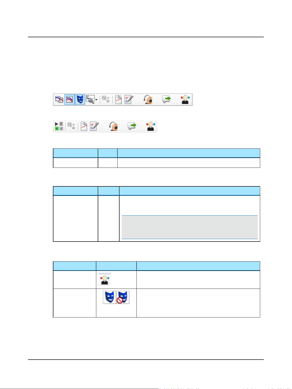
The icons and menu selections that are unique to Audiometry functionality depend on the test functions included in OTOsuite and/or whether a test device is connected.
Tone audiometry
Speech audiometry
2.2.1 File menu
Menu item Icon Description
New Audiogram
2.2.2 Edit menu
Menu item Shortcut Description
Audiometric prop-
...
erties
2.2.3 View menu
Menu item (Tone) Icon Description
Select Orientation
Masking Assistant
Ctrl+U
Select new audiogram. You will be prompted to save or cancel current data.
Click to enter Tester name, Test Date, and air conduction transducer for a manually entered audiogram.
Note•The air conduction transducer is stored when you have selected it
in the transducer section of the Control Panel (or with device controls, if
applicable) and data points are entered on the audiogram.
Click to select the perspective of the patient's ears as presented on
the screen for graph and table views.
Enable or disable the Masking Assistant.
The Masking Assistant causes an unmasked threshold to flash
repeatedly if masking is recommended.
• See The Masking Assistant ► 17.
14 Otometrics - AURICAL Aud
Page 15
Menu item (Tone) Icon Description
Overlays
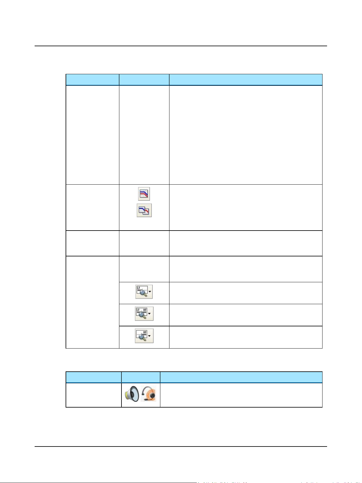
Combined Audiogram
Enables or disables the overlays. Overlays display
• pictures
• severity
• speech banana,
• speech letters,
• unusable area
on the audiogram.
Overlays can also be displayed by selecting them from the overlays
box below or next to the audiogram.
To view/hide the overlays box, select Tools> Options> General.
See Tone feature boxes ► 32.
Combined View
• Click to view both ears in a single audiogram.
Split View
• Click to view separate audiograms for each ear.
Click to toggle between viewing both ears in a single audiogram (combined audiogram) or both a left and a right audiogram on your screen.
2 Navigating in the OTOsuite Audiometry Module
Audiogram Legend
Standard / All / High
frequencies
2.2.4 Measurement menu
Menu item Icon Description
Monitoring
Click to enable or disable the display of the audiogram legend. The
legend contains the most commonly used symbols for the audiogram.
It is not configurable.
The graph shows up to 20,000 Hz. AURICAL Aud presents stimulus up
to 12,500 Hz.
• Click to choose between viewing:
Standard Frequencies
Displays the audiogram from 125 to 8000 Hz.
All Frequencies
Displays the audiogram from 125 to 20,000 Hz.
High Frequencies
Displays the audiogram from 8000 to 20,000 Hz.
Enables or disables the monitor speaker for monitoring stimuli presented
to the patient from the Stimulus or Masking channel.
Otometrics - AURICAL Aud
15
Page 16
2 Navigating in the OTOsuite Audiometry Module
Menu item Icon Description
Talk Forward
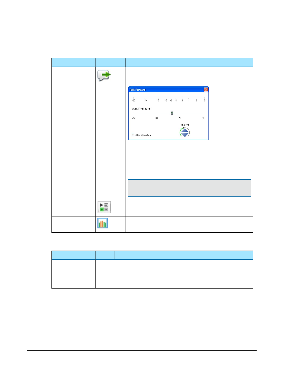
Enables communicating with the patient in the sound booth. This will display the Talk Forward dialog box, where you can control the talk forward
microphone sensitivity and the output level (in dB HL) to the patient.
When enabled, the monitor speaker will be disabled.
When the Allow stimulation checkbox is checked, you can present stimuli
while leaving Talk Forward on. This is useful when you wish to present
stimuli and verbally reinforce the patient quickly, as for instance during
pediatric testing.
Note•Be aware that background noise must not be present if
Allow stimulation is checked.
Scoring and Playing See Selecting word or phoneme scoring ► 37.
Ambient Noise
See Ambient Noise Assessor ► 64.
Assessor
2.2.5 Tools menu
Menu item Icon Description
Curves and Symbols Click to select the Curves and Symbols dialog box.
This dialog box and its related function are specific to configuring the curves and
symbols to be displayed on the audiogram or speech graph during testing.
See Curves and symbols selection ► 30.
2.3 The Patient Responder indicator
When the patient presses the Patient Responder this is shown on the Stimulus bar, and a sound signal from the PC is heard
through the Monitor Speaker or Operator Headset. The sound signal is optional (Tools> Options> Audiometry>
General> Measurement, Misc> Audible patient response).
16 Otometrics - AURICAL Aud
Page 17
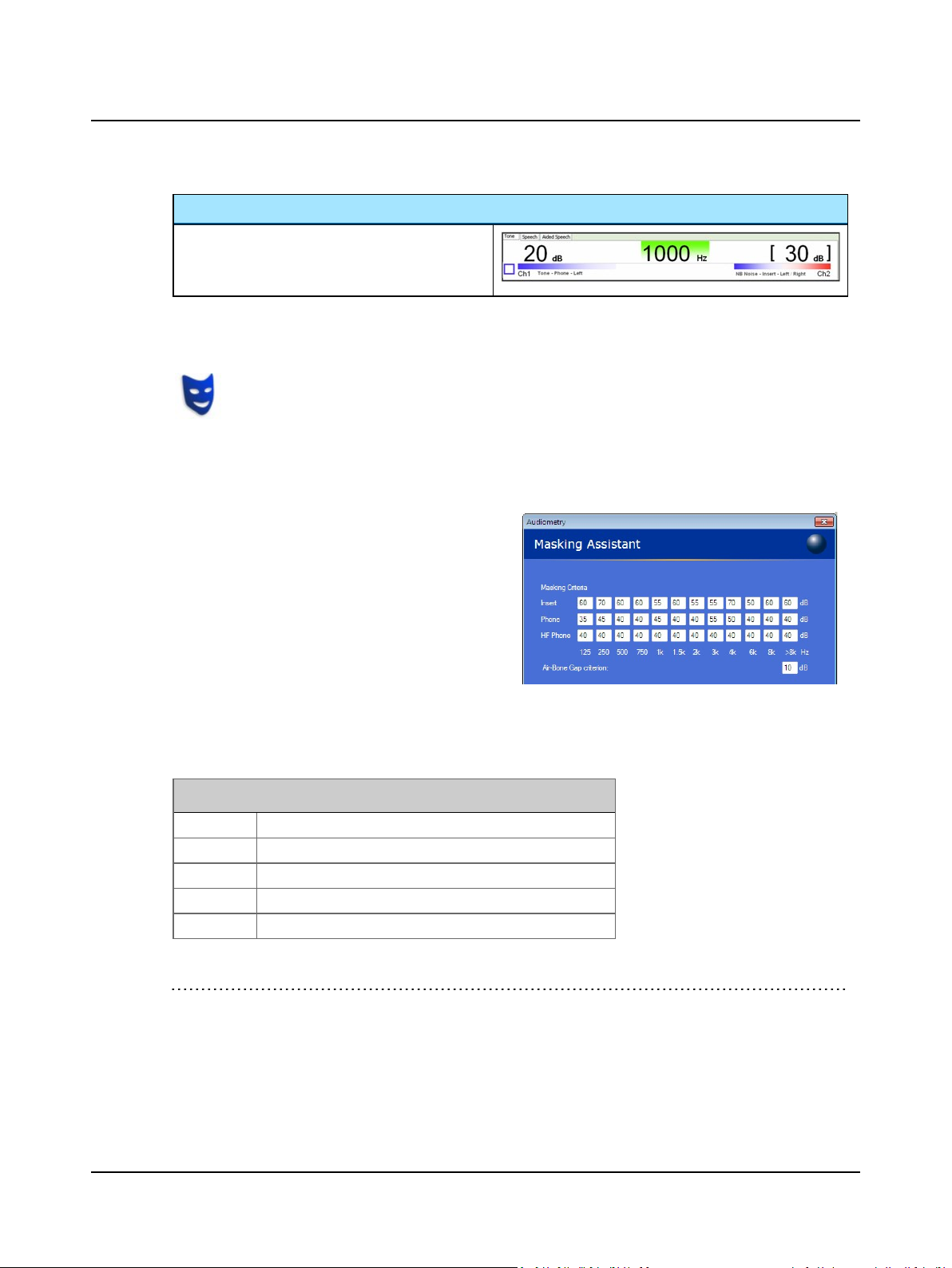
Single Responder setup
• Green
Indicates that the patient is pressing the Patient
Responder.
2.4 The Masking Assistant
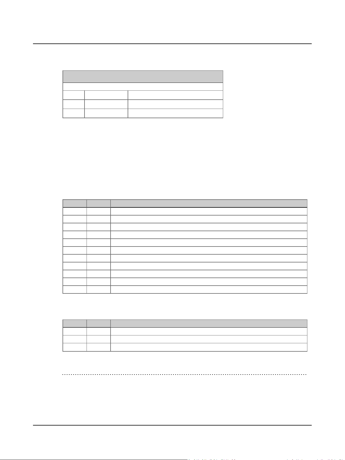
If the Masking Assistant is enabled, it will at all times check for frequencies that may require testing with
masking. This also applies to old audiograms imported from NOAH or XML as long as a supported transducer
was stored with the data.
The Masking Assistant is a tool provided to help you with an indication that there may be frequencies where testing with
masking1is recommended.
• The audiogram symbol will flash at the specific frequencies where contralateral masking may be recommended2.
• The masking criteria are configurable so that you can
set them up to match your local recommendations for
masking. You can for instance choose either frequency
specific criteria, which increases the efficacy of your
work, or the traditional "one-level-fits-all" criteria.
Select the Tools> Configuration Wizard> Audi-
ometry - Configure... > Masking Assistant to set up
the masking criteria.
2 Navigating in the OTOsuite Audiometry Module
All masking signals are calibrated in effective masking.
How does the Masking Assistant work?
Terminology
AC AC test ear
ACc AC contra
BC BC
BCc BC contra
Min IA Minimum inter-aural attenuation.
1
(Katz, J., Lezynski, J. (2002). Clinical Masking. In J. Katz, ed., Handbook of Clinical Audiology, Williams and Wilkins, Bal-
timore.)
2
Based on criteria described in Clinical Masking, Essentials of Audiology, Stanley A. Gelfand, Thieme 1997, and Meas-
urement of Pure Tone Hearing Thresholds, Audiologists’ Desk Reference - Vol 1, James W. Hall III, H. Gustav Mueller
III, Singular Publishing Group 1997. and Munro K.J., Agnew N. A comparison of inter-aural attenuation with the Etymotic ER-3A insert earphone and the Telephonics TDH-39 supra-aural earphone. Br J Audiol 1999; 33: 259-262.
Otometrics - AURICAL Aud
17
Page 18
2 Navigating in the OTOsuite Audiometry Module
When is masking required?
Masking is recommended when the following conditions are met:
AC AC > ACc + Min IA
or AC > BCc + Min IA
BC BC < AC - x* dB
Only stored thresholds measured without masking are checked. Levels which did not evoke a response are excluded from
the check. This means that as soon as a masked threshold has been stored, the flashing stops for that frequency.
* denotes configurable Air/Bone gap criterion (Tools> Configuration Wizard> Audiometry - Configure...> Masking
Assistant).
Min IA is frequency specific
These are the Min IA tables for TDH-39 and Otometrics Inserts used in the Masking Assistant1.
Min IA (supraaural phone: TDH-39), frequency specific
Hz dB
125 35 Katz & Lezynski, (2002)
250 48 Munro & Agnew, BJA (1999)
500 44 Munro & Agnew, BJA (1999)
750 40 N/A - fulfill traditional approach
1000 48 Munro & Agnew, BJA (1999)
1500 40 N/A - fulfill traditional approach
2000 44 Munro & Agnew, BJA (1999)
3000 56 Hall J.W. III & Mueller G.H. III / Munro & Agnew, BJA (1999)
4000 50 Katz J / Munro & Agnew, BJA (1999)
6000 44 Hall J.W. III & Mueller G.H. III / Munro & Agnew, BJA (1999)
8000 42 Katz J / Munro & Agnew, BJA (1999)
Min IA insert phone
Hz dB
125 60 N/A - traditional value
250 72 Munro & Agnew, BJA (1999)
500 64 Munro & Agnew, BJA (1999)
1
Katz, J., Lezynski, J. (2002). Clinical Masking. In J. Katz, ed., Handbook of Clinical Audiology, Williams and Wilkins, Bal-
timore. Munro, K.J., Agnew, N. A comparison of inter-aural attenuation with the Etymotic ER-3A insert earphone and
the Telephonics TDH-39 supra-aural earphone. Br J Audiol 1999; 33: 259-262. Hall, JW., MUELLER, HG. (1997). The audiologists’ desk reference, Volume I., Singular Publishing Group, San Diego.
18 Otometrics - AURICAL Aud
Page 19
Hz dB
750 60 N/A - traditional value
1000 58 Munro & Agnew, BJA (1999)
1500 60 N/A - traditional value
2000 56 Munro & Agnew, BJA (1999)
3000 58 Munro & Agnew, BJA (1999)
4000 72 Munro & Agnew, BJA (1999)
6000 54 Munro & Agnew, BJA (1999)
8000 62 Munro & Agnew, BJA (1999)
2.5 The Control Panels
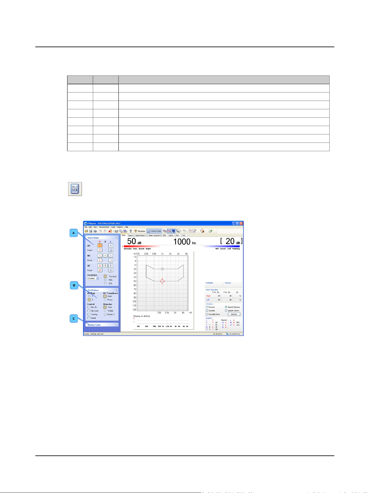
Click the Control Panel icon in the toolbar to activate the Control Panel.
The Tone Control Panel
2 Navigating in the OTOsuite Audiometry Module
A. Quick Select - Tone ► 20
B. Test Options ► 22
C. Monitor and Level ► 24
Otometrics - AURICAL Aud
19
Page 20
2 Navigating in the OTOsuite Audiometry Module
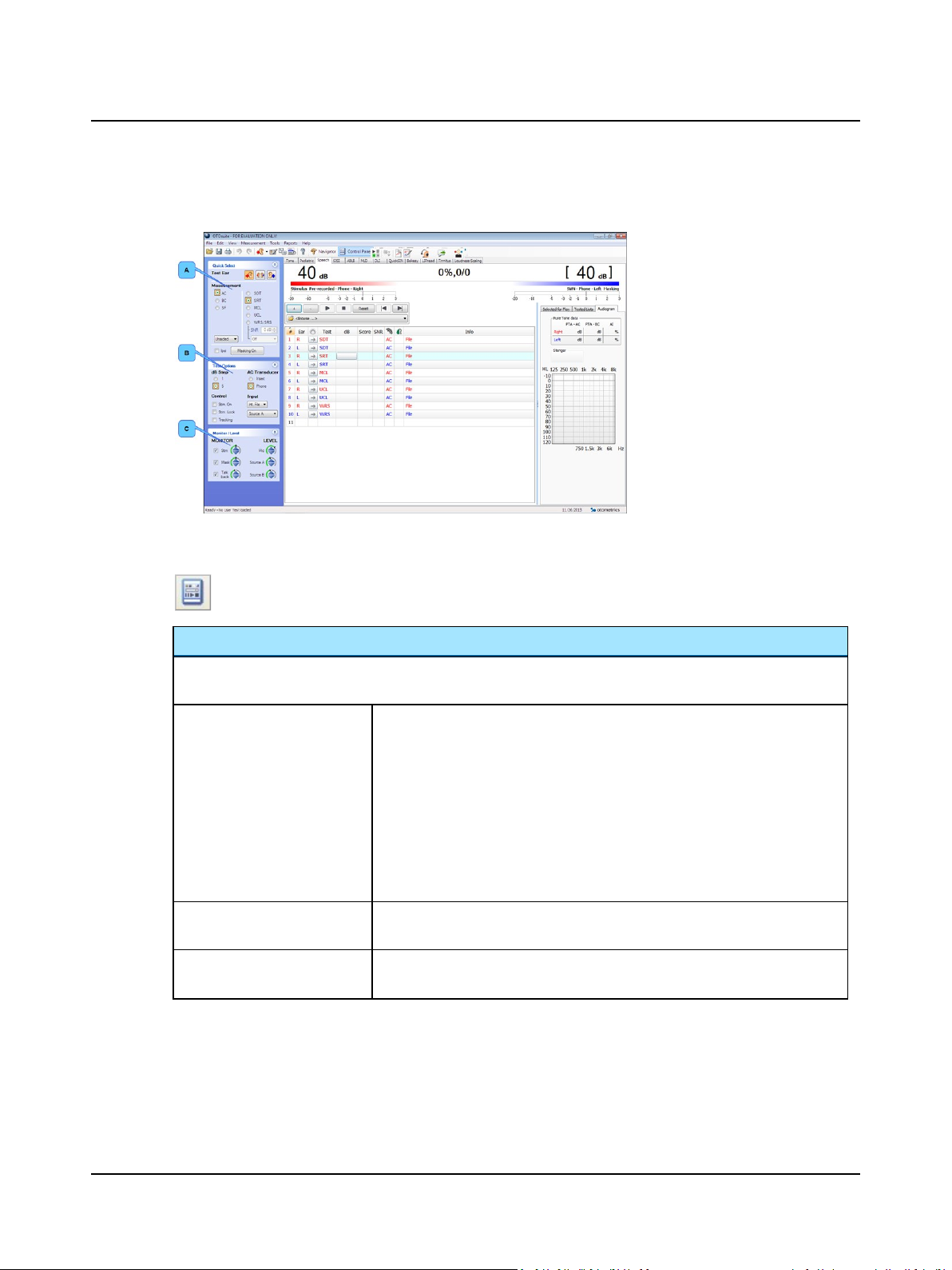
The Speech/Aided Speech Control Panel
2.5.1 Quick Select - Tone
Click the Control Panel icon in the toolbar to activate the Control Panel.
A. Quick Select - Speech ► 21
B. Test Options ► 22
C. Monitor and Level ► 24
Quick Select
Click to select the options you wish to use. You can customize the symbols to suit your purposes: See Curves and sym-
bols selection ► 30.
R, B, L
(Right, Binaural, Left)
AC (Air Conduction)
Click to select whether your transducer selections will be routed to the right, left,
or both right and left transducers.
This will also reflect on how the results are stored:
• Left symbols will be stored on the left-ear audiogram (or on the combined audiogram)
• Right symbols will be stored on the right-ear audiogram (or on the combined
audiogram)
• Binaural symbols will be stored on both audiograms (or once on the combined
audiogram)
Presents the stimulus and/or masking using the selected AC transducer.
Mask
BC (Bone Conduction)
Presents the stimulus and/or masking through the bone oscillator.
Mask
20 Otometrics - AURICAL Aud
Page 21

Quick Select
2 Navigating in the OTOsuite Audiometry Module
SF (Sound Field)
Mask
Condition
Click to select the conditions you wish to apply to the audiogram.
Condition
Click to define the viewing mode you wish to apply to the audiogram.
Threshold
MCL
UCL
2.5.2 Quick Select - Speech
Click the Control Panel icon in the toolbar to activate the Control Panel.
Presents the stimulus and/or masking through the soundfield speakers.
• If you are using only 2 speakers, the routing is determined by the typical routing controls (left, right, binaural).
• If you are using only 2 speakers, you can set up a channel to provide stimulus/masking via a different transducer (i.e. when providing masking to one ear
and stimulating the other ear using the soundfield speakers).
• Unaided
• Aided Speech 1
• Aided Speech 2
Threshold view
Most Comfortable Level view
UnComfortable Level view
Test Ear
Click to select the test ear to be recorded in the audiogram.
Measurement
Click to select the transducer type used.
AC
BC
SF
Otometrics - AURICAL Aud
• Left/Both/Right
• Air Conduction
• Bone Conduction
• Sound Field
Note•Sound-field testing is not available on some models.
21
Page 22
2 Navigating in the OTOsuite Audiometry Module
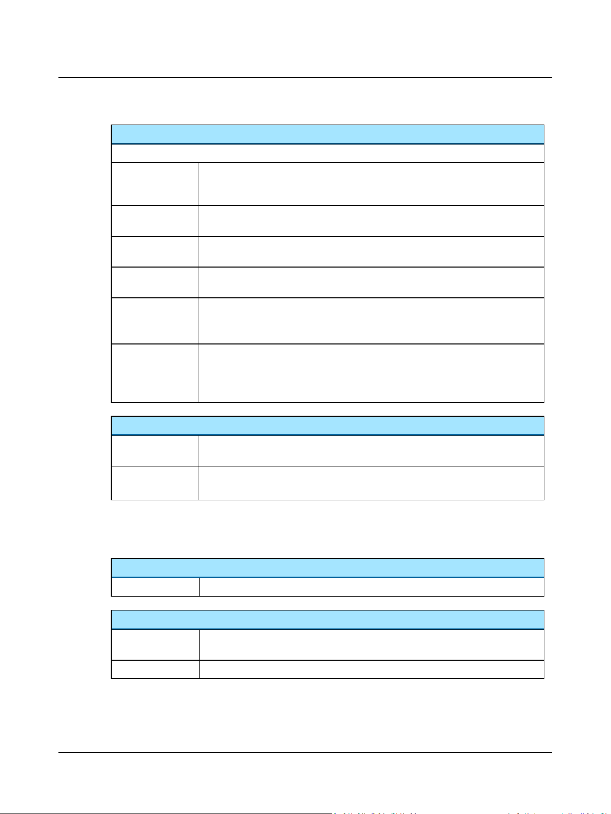
Measurement
Click to select the condition you wish to apply to the audiogram.
SDT • The data will be stored as a S peech D etection T hreshold. This is the lowest level at
which the patient responds to speech at least 50% of the time (also known as SAT - Speech
Awareness Threshold).
SRT • The data will be stored as a S peech R eception T hreshold. This is the lowest level at
which the patient repeats at least 50% of spondaic words correctly.
MCL • The data will be stored as a M ost C omfortable L oudness level. This is the level at which
the patient reports it is most comfortable to listen to the speech stimulus.
UCL • The data will be stored as an U nC omfortable L oudness level. This is the level at which
the patient reports that the speech stimulus is uncomfortably loud.
WRS/SRS • The data will be stored as a W ord R ecognition S core or S entence R ecognition S core.
This test requires monosyllabic words to be presented at the patient's MCL level or above.
The patient is instructed to repeat the words he or she hears.
SNR/dB step • S ignal to N oise R atio in dB step.
If you check SNR , you can report a S ignal to N oise R atio in the speech result description box. This also stores the speech data as a "speech in noise" test and is accordingly differentiated from a regular speech measurement.
IPSI routing
IPSI
Masking/Stimulus 2
On
2.5.3 Test Options
General options
dB Step
1, 5 (dB)
AC Transducer
Insert Presents the stimulus or masker through the insert earphones. See Configuring the Audi-
Phone
• Click to select the IPSI routing. IPSI routes the non-stimulus channel to the same ear as the
speech stimulus. That way, a speech in noise test can readily be administered.
• Click Masking/Stimulus 2 On to enable non-stimulus channel presentation.
This selection depends on the Input selection for the non-stimulus channel.
Defines the intensity of the stimulus and masker used to record the audiogram.
ometry Module ► 101.
Presents the stimulus or masker through supra-aural headphones.
22 Otometrics - AURICAL Aud
Page 23
Control
2 Navigating in the OTOsuite Audiometry Module
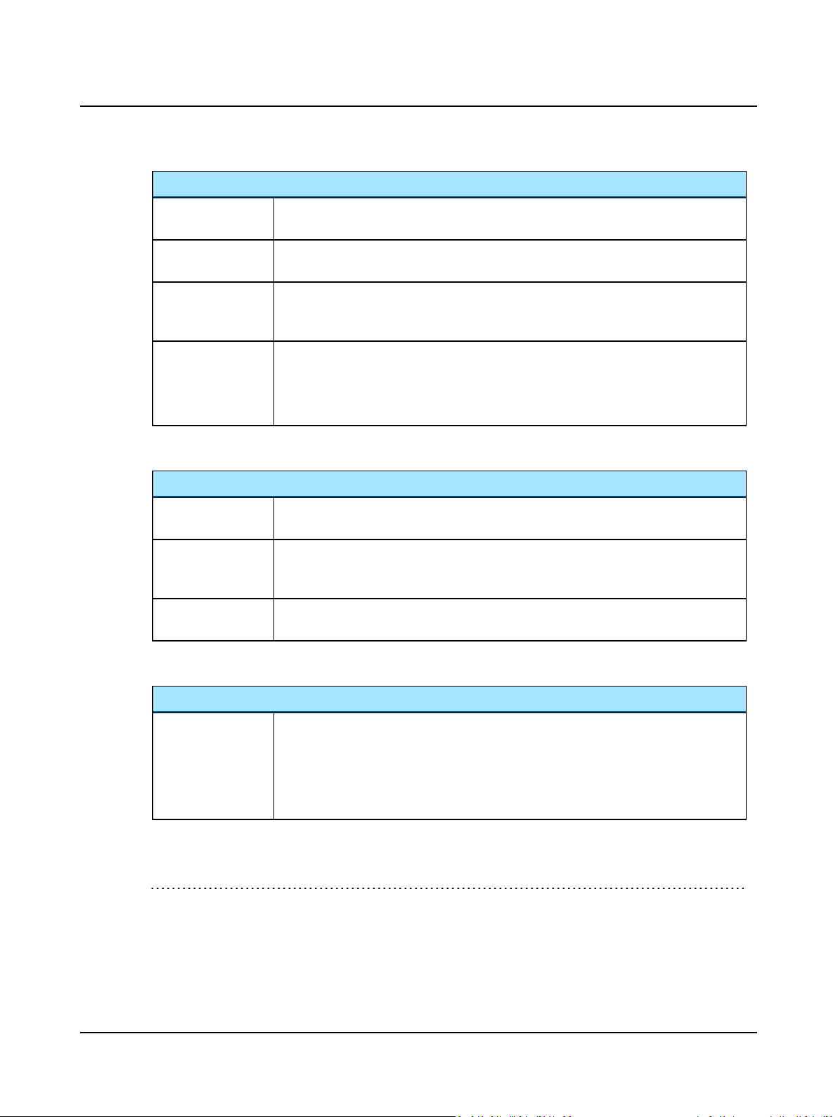
Stim On
Stim. Lock
Tracking
When checked, the stimulus will be continuously on and will turn off when you press the stimulus button.
The stimulus/masker from both channels will be presented simultaneously if this option is
enabled.
When the intensity of the stimulus/masker for a channel is increased/decreased by xdB the
intensity of the stimulus/masker for the other channel will also increase/decrease by the same
xdB if this option is enabled.
Pulsed Tone only:
The stimulus pulses 200ms on and 200ms off if this option is enabled.
The pulse duration is configurable: Select Tools> Options...> Audiometry> Tone> Meas-
urement> Pulsed.
Tone specific options
Stimulus
Tone
Warble
FRESH Noise
Presents a pure tone as the stimulus type.
• 125Hz to 12,500Hz is standard.
Presents a warbled pure tone as the stimulus type. This stimulus type should be used for sound
field testing to avoid any standing waves. Warble depth and rate are configurable: select
Tools> Options> Audiometry> Tone> Measurement, Misc> Warble.
Presents the customized FRESH noise as the stimulus type.
FRESH stands for FREquency Specific Hearing assessment noise.
ab
Speech specific options
Input
Speech material
source (drop down
list)
a
The FRESH noise is implemented according to specifications of "Stimuli for Sound Field Audiometry: A Response to
Lippmann and Adams", G. Walker and H. Dillon, 1984 in Journal of Speech and Hearing Disorders, p 219, and H. Dillon
(2008), personal communication.
b
For more information read: "Narrow Band Noise Audiometry: The Effect of Filter Slope", Daneil J. Orchik and Nancy L.
Mosher, 1975 in The Journal of American Audiology Society, Vol. 1, No. 2, p.50-53.
Otometrics - AURICAL Aud
Determines the input to Source A and Source B.
The options are:
• Int. File (stored on hard drive),
• Int. CD (internal CD drive built into the PC),
• Line In (external medium connected to the PC).
23
Page 24
2 Navigating in the OTOsuite Audiometry Module
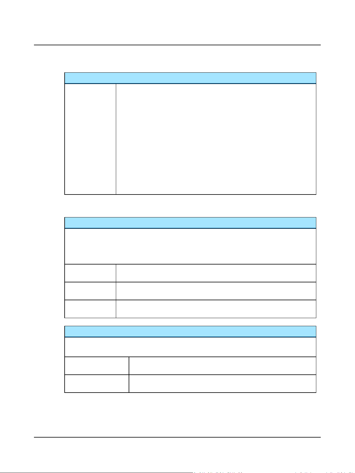
Input
Source...
2.5.4 Monitor and Level
Monitor
The signal level changes in 3dB steps with each click of the arrow up or arrow down buttons.
• To change the signal level by more than one click at a time, use the mouse scroll wheel.
• The check boxes are used for enabling/disabling of monitoring. You can also define this in Tools> Options> Audi-
ometry> General> Measurement> Monitor.
The options are:
• Mic
For live voice speech testing by the Operator. The operator presents live speech material
through a microphone.
• Source A
Delivers recorded speech material from sourceA.
• Source B
Delivers recorded speech material from sourceB
• Source A+B
Delivers recorded speech material from sourceA and B. This is only possible for the integrated speech material, if it has been prepared for this.
• Source B+A
Delivers recorded speech material from sourceB+A. This is only possible for the integrated speech material, if it has been prepared for this.
Stim
Mask
Talkback
The stimulus can be monitored if this option is enabled. The indicator displays the level of the
signal.
Masking can be monitored if this option is enabled. The indicator displays the level of the signal.
Talkback can be monitored if this option is enabled. The indicator displays the level of the signal.
Level
The signal level changes in 1dB steps with each click of the arrow up or arrow down buttons.
• To change the signal level by more than one click at a time, use the mouse scroll wheel.
Mic
For adjusting the sensitivity of the test microphone reflected on the VU meter (only
used for Speech testing).
Source A, Source B For adjusting the sensitivity of the signal coming from Source A or Source B reflected on
the VU meter (only used for Speech testing).
24 Otometrics - AURICAL Aud
Page 25
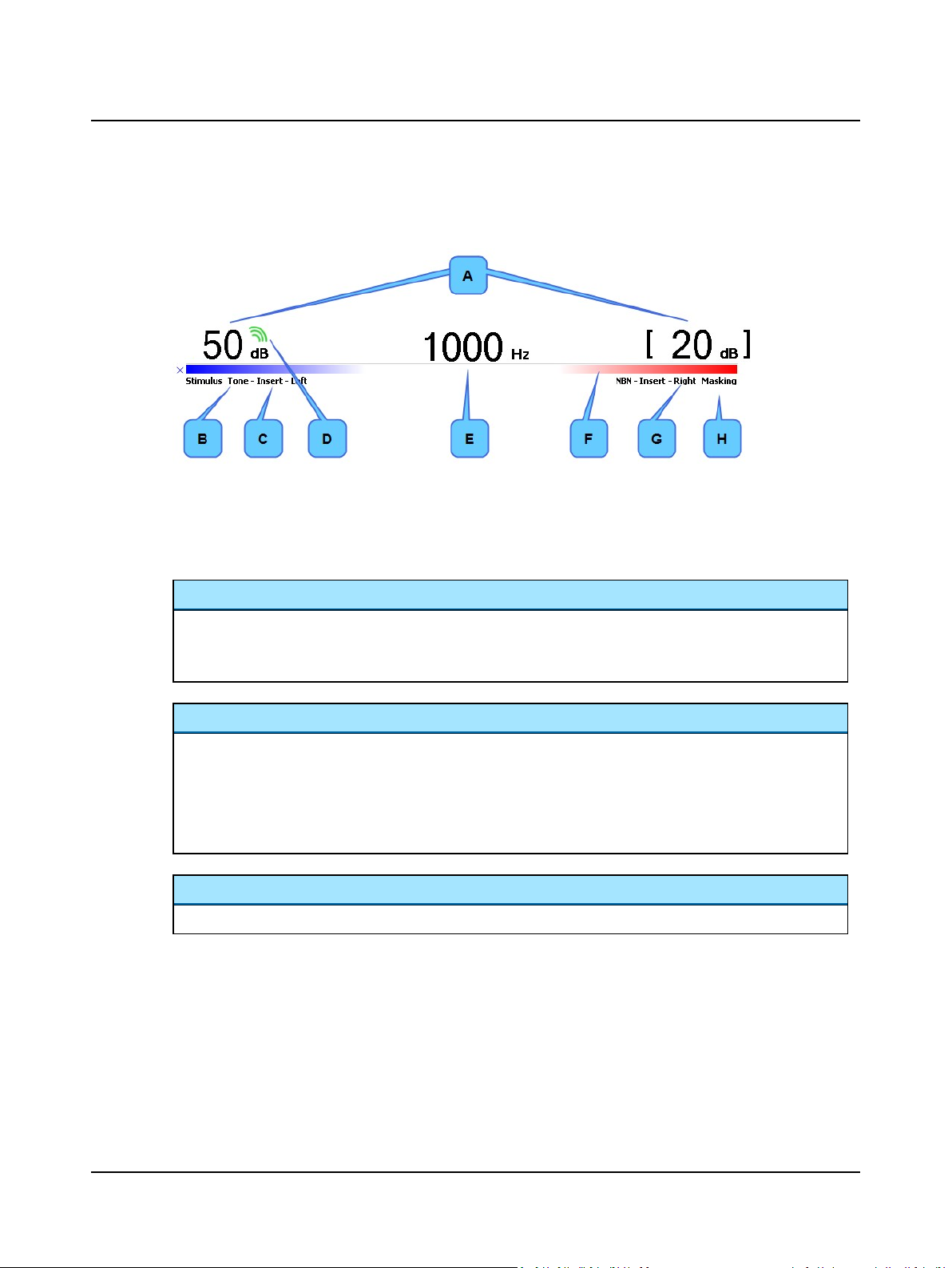
2.6 The stimulus bar
2 Navigating in the OTOsuite Audiometry Module
A. Intensity
B. Stimulus indicator
C. Transducer indicator
D. Stimulus being presented
E. Frequency
F. Stimulus bar color
G. Routing indicator
H. Masking on
Intensity
Indicated by the dB level above the channel status bars.
• Masking is denoted by square brackets around the level (calibrated in effective masking level).
• The green triple wave symbol above the level indicates that the stimulus is currently being presented.
Stimulus bar color
Indicates the routing for each channel:
• Blue = left ear
• Red = right ear
• Blue/Red = binaural
• Gray = unspecified
Stimulus, transducer and routing indicators
The stimulus/masking type, the transducer and the routing for each channel.
2.6.1 Test controls
Test controls provide a means of operating the audiometer if you use the mouse and on-screen options to perform tests.
• To enable test controls, select Tools> Options> Audiometry> General> On-screen controls> Show> On.
Otometrics - AURICAL Aud
25
Page 26
2 Navigating in the OTOsuite Audiometry Module
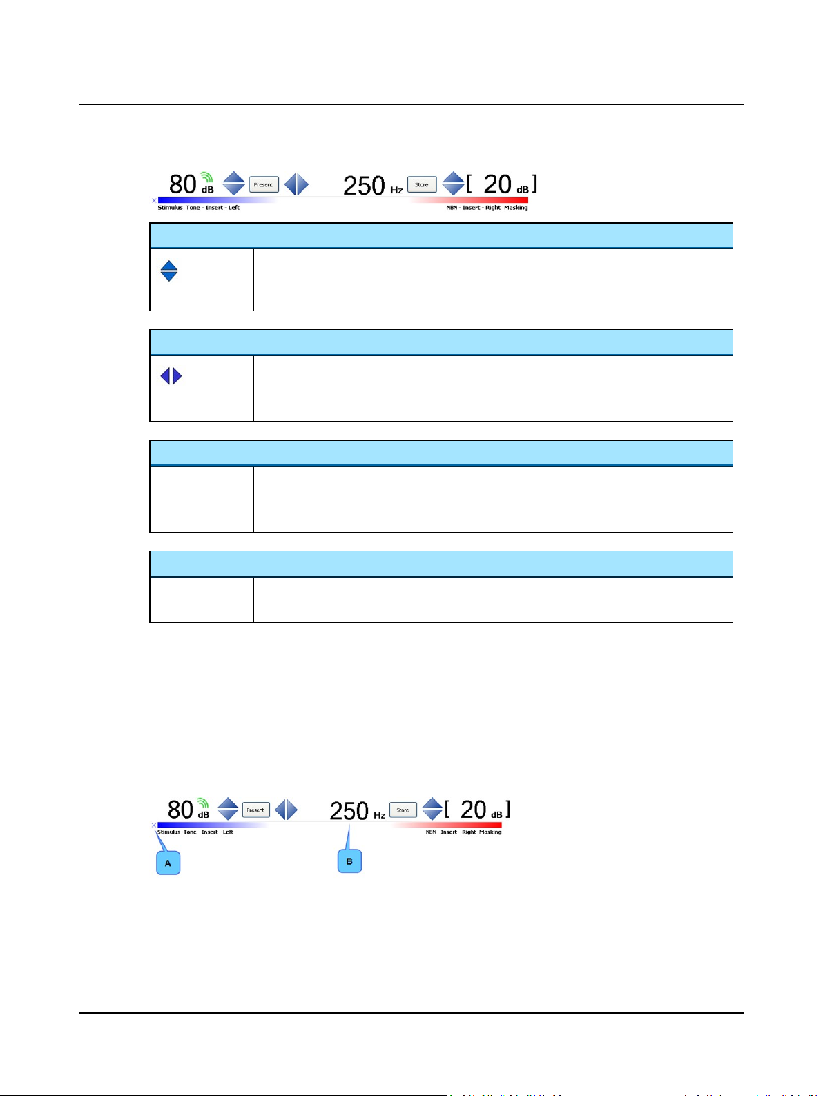
Up and down arrows
Tone and Speech. Stimulus and Masking
• The Arrow Up and the Arrow Down buttons change the stimulus level depending on the set-
ting in Tools> Options> Audiometry> Tone> Misc.> Level Direction of Arrow Keys.
Left and right arrows
Tone. Stimulus and Masking
• Arrow left decreases the stimulus frequency.
• Arrow right increases the stimulus frequency.
Stimulate button
Present Tone
• Presents stimulus.
• If Continuous On is enabled, activating the button interrupts the stimulus.
Store button
Store Tone and Speech
• Stores the data point on the audiogram(s) or in the Speech screen.
Silence Mode
Silence Mode allows you to control tone levels and presentation by hovering the mouse cursor over the respective onscreen controls. This is particularly useful when the operator of the audiometer and the person being tested are in the
same room.
• To enable silence mode, select Tools> Options> Audiometry> General> On-screen controls> Silence Mode> On.
• To change the level and frequency by more than one click at a time, use the mouse scroll wheel.
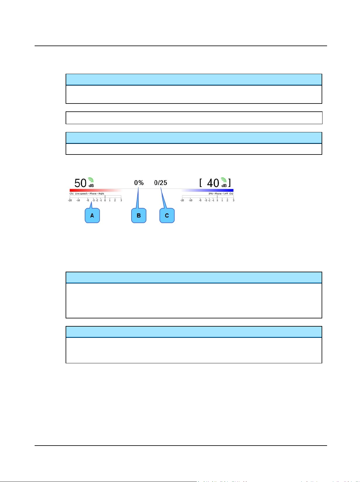
2.6.2 The Tone stimulus bar
A. Symbol B. Frequency
During online testing, the stimulus bar shows:
26 Otometrics - AURICAL Aud
Page 27
2 Navigating in the OTOsuite Audiometry Module
Symbol
• Indicates the symbol that will be displayed on the audiogram(s) when a data point is stored. The symbol shown
reflects the current audiometer measurement settings.
See also
Curves and symbols selection ► 30
Frequency
• Indicated by the Hz value in the center of the stimulus bar.
2.6.3 The Speech stimulus bar
A. VU meter
B. Speech score
C. Word count
During online testing, the stimulus bar shows:
Speech Score/Word Count
• Displays the percentage correct/incorrect and the amount of words correct/incorrect out of a given number of
words. You can display speech score and word count either as “% Correct” or as “% Incorrect”. To set your preference, select Tools> Options> Speech> Misc.> Score Presentation.
% Correct is the default setting.
.
VU Meter
• Displays the level (in volume units) of the test microphone or speech material from Source A or Source B. Speech
should always be delivered at 0dB on the VU meter so that the dB level on the stimulus intensity bar represents
the level actually being delivered to the patient.
2.7 The Tone test screen
During online testing, the screen reflects the test done by the audiometer as it progresses.
Otometrics - AURICAL Aud
27
Page 28

2 Navigating in the OTOsuite Audiometry Module
2.7.1 The work area in the Tone screen
The Tone test work area consists of a range of elements for viewing and selecting various features:
• The audiogram ► 28
With a description of audiogram elements, how to view single or dual graphs, and how to view the intensity levels
used for masking.
• Tone feature boxes ► 32
With a description of result boxes for special tests, utilities such as a timer and an overlays selector, and instructions
for how to view/hide the feature boxes.
A. Stimulus bar
B. Work area
C. Feature boxes
2.7.2 The audiogram
Audiogram elements
Cross hatch
Indicates your current stimulus level and frequency. The color indicates the routing:
• Blue = left
• Red = right
• Black = binaural
Mouse cursor
Indicates where you place the mouse. The color indicates the routing:
• Blue = left
• Red = right
• Black = binaural
28 Otometrics - AURICAL Aud
Page 29
Audiogram
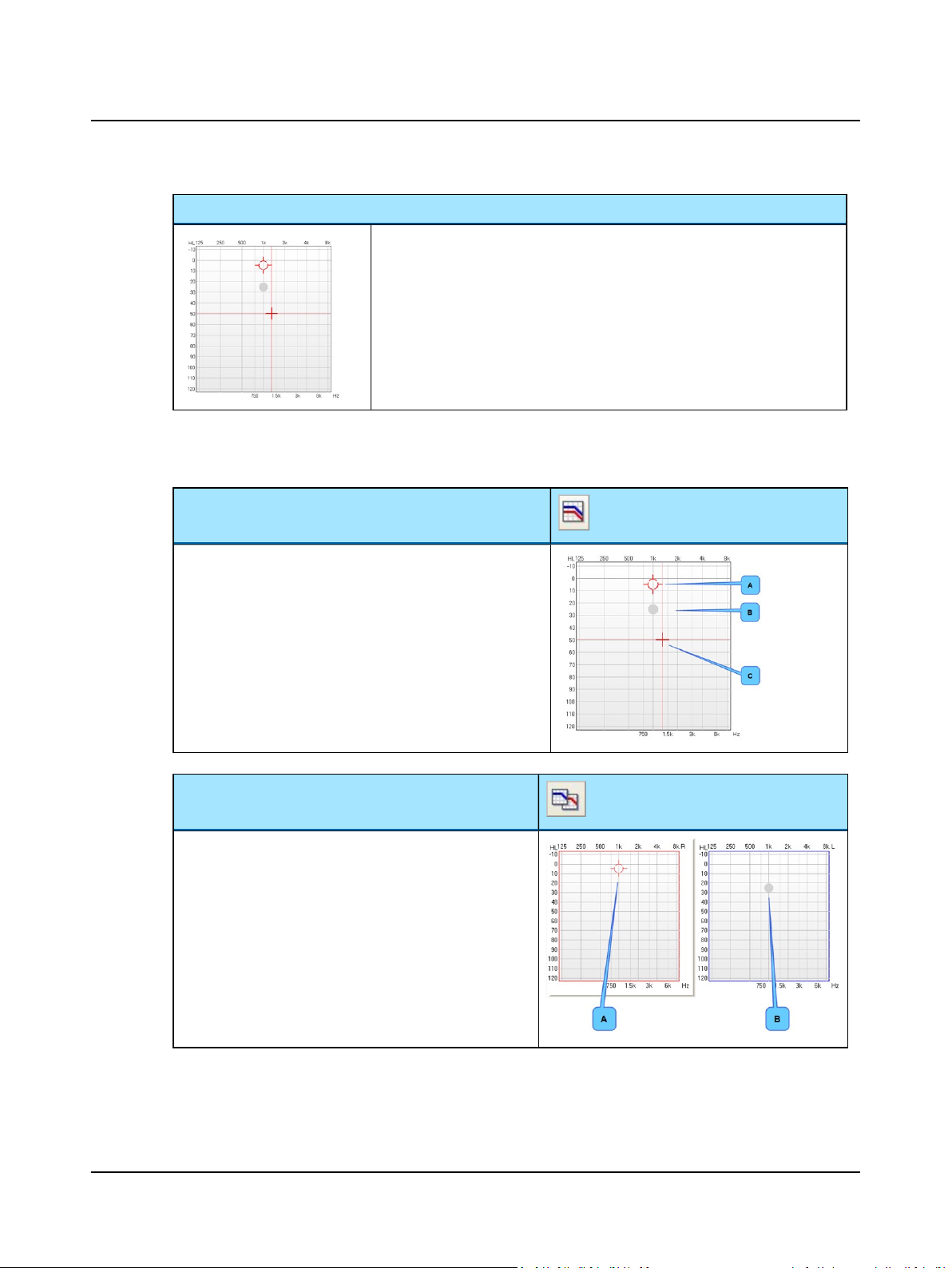
Viewing the audiogram
You can choose between:
Single graph view
A. Stimulus marker (ear color)
B. Masking level indicator
C. Mouse cursor (ear color)
2 Navigating in the OTOsuite Audiometry Module
• Intensity is shown to the left of the audiogram in dBHL.
• Octave frequencies are shown below the audiogram in Hz.
• Interoctave frequencies are shown above the audiogram in Hz.
Dual graph view
When you use the dual graph viewing option, the graph that
corresponds with the stimulus ear will have a gray outline to
denote the active audiogram.
You can switch the position of the right and left graphs to correspond to your viewing preference.
1. Select Tools> Options> Tone> Misc.> Dual Graph View
or in the menu bar under View.
A. Stimulus marker (ear color)
B. Masking level indicator
Otometrics - AURICAL Aud
29
Page 30
2 Navigating in the OTOsuite Audiometry Module
Viewing masking levels
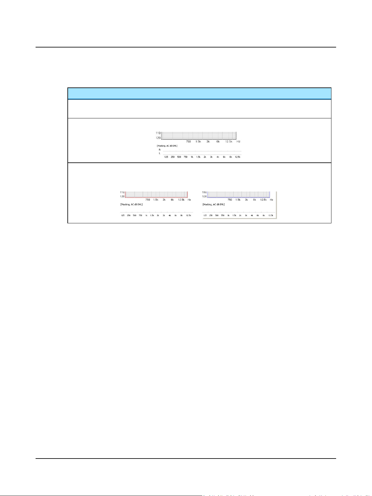
Masking levels
Below the audiogram, the intensity levels used for masking can be displayed. It is an option to display the masking
levels. Select Tools> Options> Tone> View> Misc.> Masking Levels.
• In combined view, the non-test ear masking levels are shown below the graph.
• In Dual Graph View, the masking level used for masking the non-test ear is by default displayed under the graph
for the test ear. The masking level can be set to be displayed either under the test ear or under the non-test ear:
select Tools> Options> Tone> View> Misc> Masking Table Placement.
2.7.3 Curves and symbols selection
You can select a symbol and/or a curve style for a specific measurement and you can create new symbols.
2.7.3.1 Selecting a symbol or curve
You can select a symbol and/or a curve style for a specific measurement.
1. Select Tools> Curves and Symbols...
2. Click on the selections that apply to your measurement under Test, Transducer, and Aided Condition. The current
symbols and line style are shown.
3. Double-click on the symbol you wish to change. The Symbols selection dialog box is shown.
4. Double-click on the symbol you wish to use.
5. To change the line style of the curve, select from the Line Style drop-down list.
6. To change the color, double-click on the current Color square. Select a new color or click on Define custom colors>>
to select a color not shown. Click OK.
7. To optimize viewing of the audiogram, you can offset the symbols in relation to the audiogram grid in the fields Hori-
zontal Offset and Vertical Offset.
30 Otometrics - AURICAL Aud
Page 31
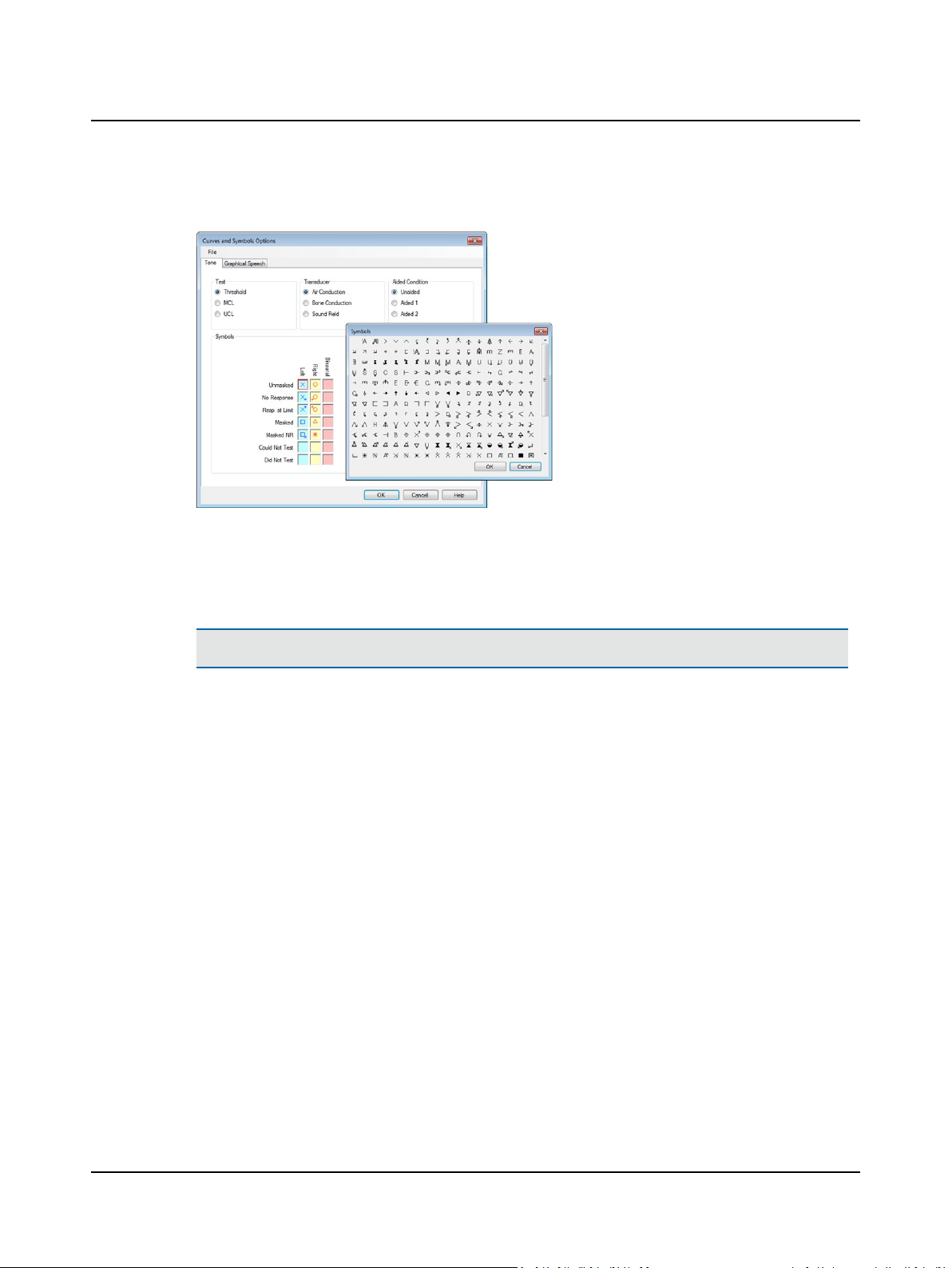
You can superimpose symbols on the audiogram where two different points share the same value (i.e. air and bone
threshold). In order to see both superimposed symbols, you can define an offset direction for each individual symbol.
2.7.3.2 Creating new symbols
1. Use Microsoft Powerpoint to create graphics that can be saved in Enhanced Meta Files (*.emf) format.
2. The outer size of the EMF file must be less than or equal to 1x1inches (2.5x2.5cm).
2 Navigating in the OTOsuite Audiometry Module
Note•If the symbols are created larger, this may severely compromise the performance of OTOsuite.
The standard symbols are drawn within a centered inner frame of 1.5 x 1.5 cm (0.6 x 0.6 inches).
The area between the inner and outer frames is used for additions to the main symbol, such as arrows for No
Response or Response at Limit, and designators for Aided Left or Aided Right.
3. Before you store the new graphic, make sure that the outer and inner frames are invisible: Select the frame, and set
the line color to No Line. Repeat this for each frame.
4. To save as an *.emf graphics file, select all elements in the drawing (including the invisible outer frame as well as the
symbol itself centered within the frame). Right-click and select Save as picture...
5. Name the file and select the file type *.emf.
6. Save it in C:\Program Files\GN Otometrics\OTOsuite\AudSymbols.
7. Launch the OTOsuite Audiometry Module and select Tools> Curves and Symbols.
The new symbol should appear on the list of symbol options.
In this dialog box, you also have options for setting the color, line type, and horizontal and vertical offsets that will
apply when you use the new symbol.
Otometrics - AURICAL Aud
31
Page 32
2 Navigating in the OTOsuite Audiometry Module
2.7.4 Compare audiograms
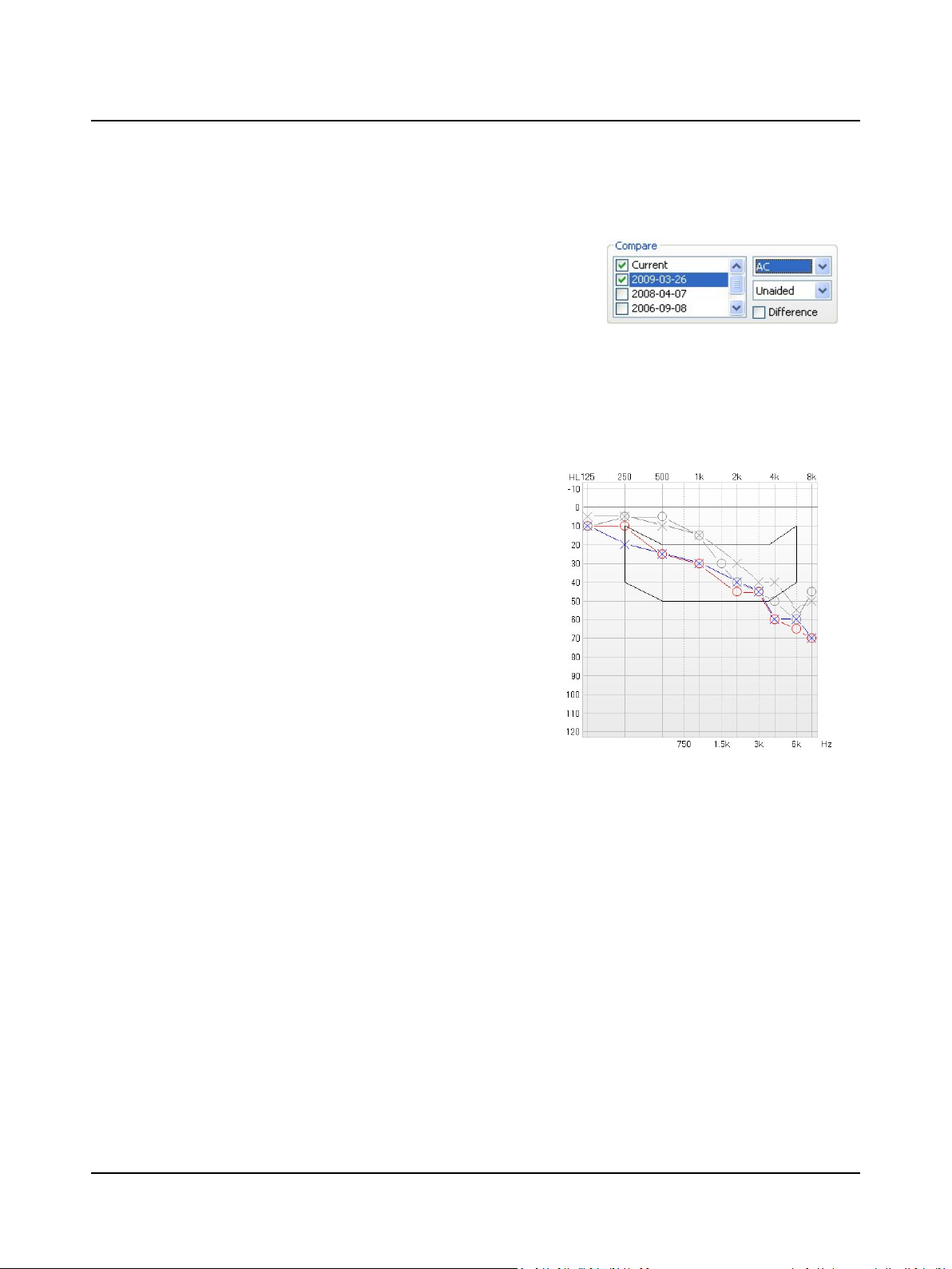
Make sure the feature box for Compare Audiograms is visible in the OTO-
suite main view area (if not, set Tools> Options> Tone> View> Show
Compare Audiograms to On).
OTOsuite under NOAH
All sessions relating to the selected client, and containing audiometry data are automatically loaded into the Compare
Audiograms feature box.
Compare current and historical audiograms
1. In the Compare Audiograms feature box, single-click to select
the audiograms you wish to view from the list of historical audiograms. Any selected historical audiogram will appear with grey
curves in the audiogram graph.
2. All curves of the selected audiograms are viewed and compared
simultaneously unless you explicitly select a curve type from
the feature box drop-down lists. The lists let you define the test
type and aided condition that you wish to view and compare.
3. You can enhance the compare view by enabling the Difference
view. This is done by checking the Difference option in the fea-
ture box. The Difference view highlights any difference
between the most recent and any older audiogram curves selected in the list.
4. If you decide to make a new audiogram, then a new Current audiogram is generated in the Compare Audiograms fea-
ture box list, and what was previously the current audiogram consequently becomes a historical one, displayed with
measurement date.
5. If you deselect the viewing of a Current audiogram so that it is no longer shown, then it will instantly be reselected if
you try to edit a curve.
6. You can keep any previously collected audiogram visible in the graph while collecting the current audiogram simply by
keeping it selected in the Compare Audiograms feature box while measuring.
2.7.5 Tone feature boxes
You can access a number of Tone view options directly from the Tone main screen.
The view options can be turned on/off. To do so, select Tools> Options> Tone.
32 Otometrics - AURICAL Aud
Page 33
Feature boxes
2 Navigating in the OTOsuite Audiometry Module
Weber
Stenger
Rinne
Reliability
Displays the results of a Weber test.
• Scoring options are left (arrow left), right (arrow right) or center (arrow up).
Displays the results of a pure tone Stenger test.
• Scoring options are positive (+) or negative (-).
Displays the results of a Rinne tuning fork test.
• Scoring options are positive (+) or negative (-).
Displays the reliability of the patient's responses (good, fair, poor).
Timer Allows you to time the length of a tone presentation (e.g. during Tone Decay test-
ing).
• The arrow starts the timer.
• The square stops the timer.
• The Reset button resets the timer to 00:00.
Pure Tone Data
Displays the pure tone average (PTA) for air conduction and bone conduction as well
as the articulation index (AI).
• The AI is calculated according to the “Count-the-dot” method.
• To configure PTA calculation, select Tools> Options> General> Misc> PTA Fre-
quency Multipliers AC/BC.
Tone Decay
Displays the results of the tone decay test.
Scoring options are:
• Rosenberg Method (Normal, Mild, Moderate, Marked) or
• Jerger STAT Method (Negative, Positive).
Overlays
Otometrics - AURICAL Aud
Select the overlay to be displayed on the audiogram.
These overlays assist in the counseling process.
• Select Tools> Options> Audiometry> Tone> Overlay Selection Box.
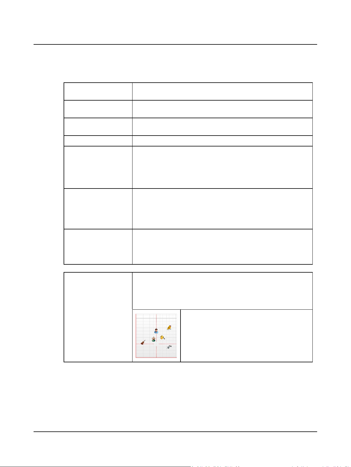
The overlay options are:
Pictures
Displays pictures representing common environmental sounds
at their approximate dBlevel (e.g. bird, plane).
33
Page 34
2 Navigating in the OTOsuite Audiometry Module
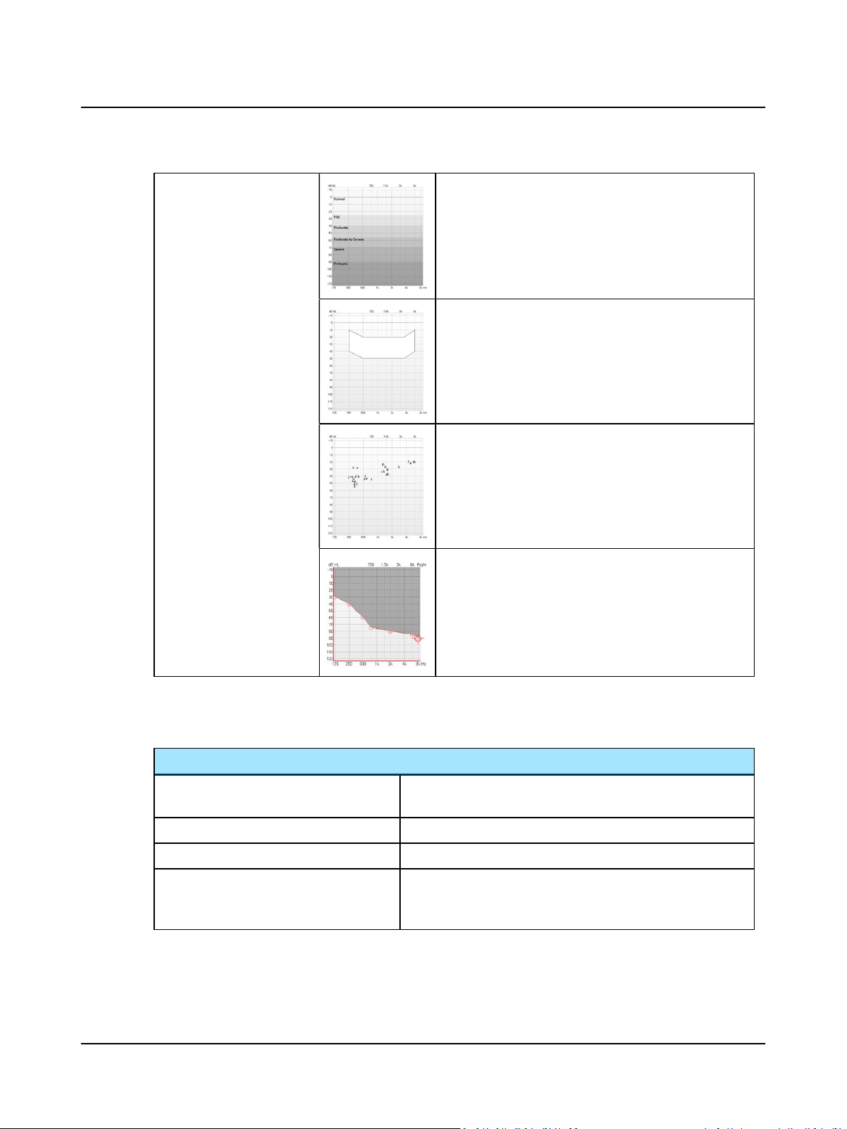
Severity
Displays the audiometric severity levels (normal, mild, moderate, moderate-to-severe, severe, profound).
Speech Banana
Displays the speech banana of a listener with normal hearing.
Speech Letters
Displays speech sounds at their approximate dB level.
2.7.6 Tone editing options
When you right-click on the main screen in Tone mode, the following options appear:
Tone editing options
Selected Point (e.g. Left AC threshold, 1kHz)
Delete Point
Delete Curve
Insert “No Response”
Unusable area
Shades the area which is outside the patient's dynamic range
of hearing.
If more than one symbol is at the same intensity/frequency, select
the data point of interest from the drop-down list.
• Deletes a selected data point.
• Deletes a selected data curve.
• Inserts a “no response” symbol (default: symbol with arrow downward) on the audiogram. You can also access the “no response”
symbol by holding down the "S" key on the keyboard.
34 Otometrics - AURICAL Aud
Page 35
Tone editing options
2 Navigating in the OTOsuite Audiometry Module
Insert “Response at Limit”
Insert "Did Not Test" • Inserts a "Did Not Test" symbol (default: symbol with DNT) on
Insert "Could Not Test" • Inserts a "Could Not Test" symbol (default: symbol with CNT) on
2.8 Work-flow related features
2.8.1 Selecting orientation
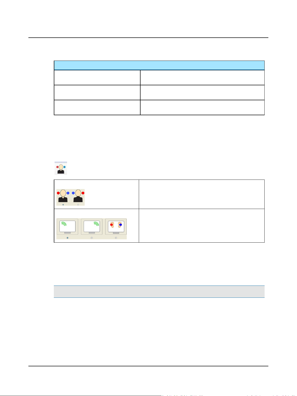
Select graph, table and control layout
Graphs and Tables
Control
• Inserts a "response at limit" symbol (default: symbol with arrow
upward) on the audiogram.
the audiogram.
the audiogram.
Click Select Orientation on the toolbar to see the following dialog:
Click to select the way you view the patient in relation to your monitor.
Click to select the position of the stimulus channel on the screen.
2.8.2 Automatic frequency/level shift when storing
When you use the Wrap or Butterfly method for testing, this feature enables you to speed up the test process by auto-
matically shifting frequency (and level) when you store a point in the audiogram. To do so, select Tools> Options> Tone>
Measurement> Auto Freq./Level Shift.
Note•Masking is always switched off when the frequency is changed automatically.
You can set up the definitions for each of the test types THR/MCL and UCL individually:
Otometrics - AURICAL Aud
35
Page 36
2 Navigating in the OTOsuite Audiometry Module
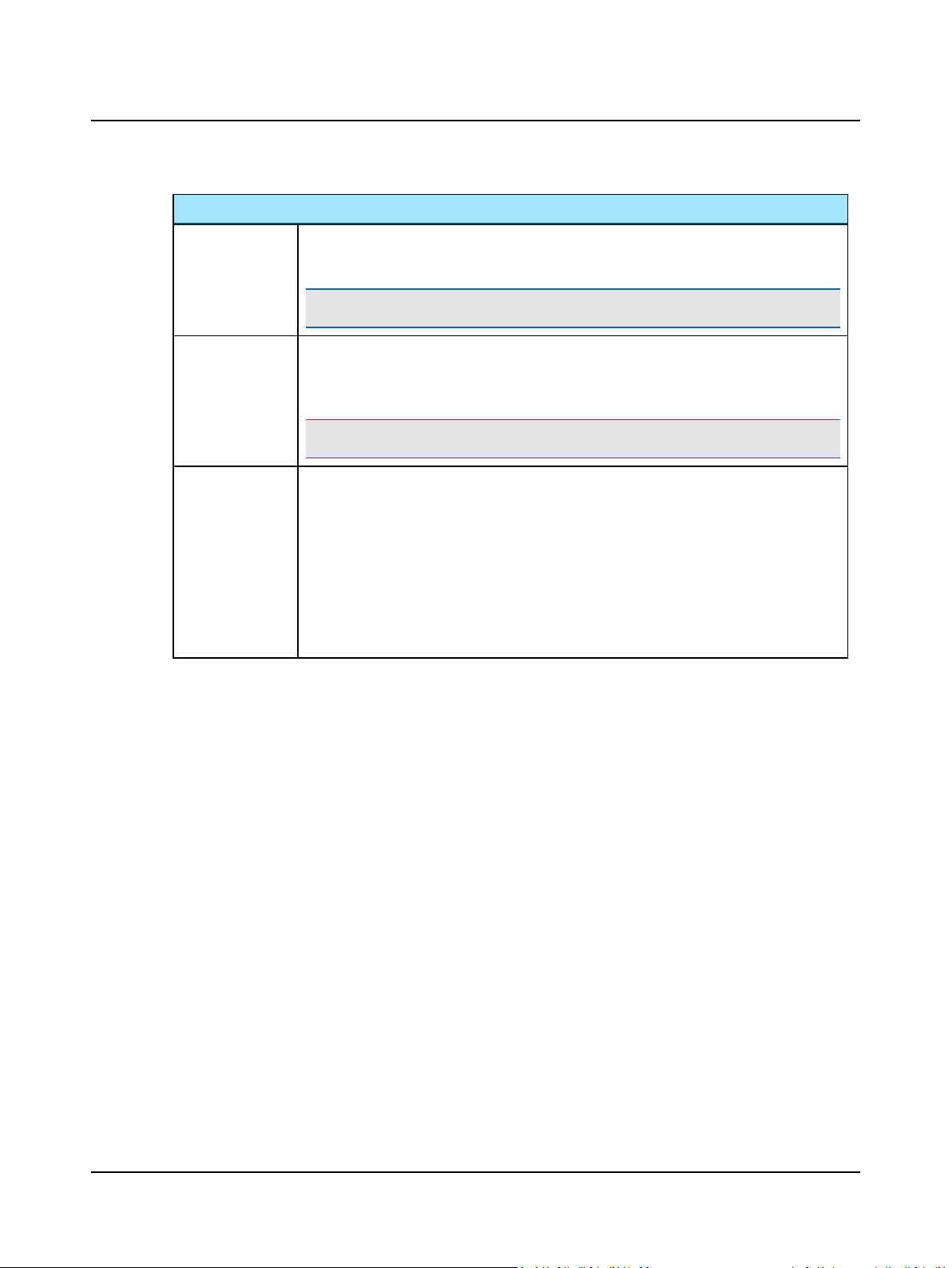
Options
Included AC/BC/SF
Frequencies
Level Shift when
Storing
Frequency Shift
when Storing
(None, Wrap, Butterfly)
Defines which frequencies to exclude from the automatic frequency shift. The actual available
frequency range is defined by the selected transducer.
Note•You can always select any frequency manually.
You can choose whether the new level should be referenced to the previous data point or be set
to a fixed level. If a data point already exists at the new frequency, this will be used as a reference point.
Note•The automatically selected level never exceeds 80dBHL for reasons of safety.
• Wrap:
Automatically selects the next, higher frequency. When it reaches the highest available frequency, it wraps around to the lowest frequency.
• Butterfly:
Automatically selects the next, higher frequency. When it reaches the highest available frequency, it goes to 1000 Hz and automatically selects the next, lower frequency. When it
reaches the lowest frequency, it automatically goes to 1000Hz.
The direction depends on whether the previous data point was stored at a higher or lower
frequency.
2.8.3 Stimulus duration
You can set a fixed duration of the presentation of the tone stimulus. To do so, select Tools> Options> Tone> Meas-
urement> Stimulus Duration.
2.8.4 Ear shift frequency and level setting
When you change test ear, you can define that the frequency and level should be set to 1000Hz at 20dBHL. To do so,
select Tools> Options> Tone> Measurement> Ear Shift Frequency and Level. Check Ear Shift Frequency and Level.
2.8.5 Saving non-stimulus channel as masking
If you use an external masking signal (non-audiometer masking noise) for speech masking, you can choose to store the
presentation level of the non-stimulus channel as a masking level.
To do so, set Tools> Options> Speech> Measurement> Use Non-Stimulus Channel as Masking to Yes.
2.9 The Speech test screen
Selecting the work area in the Speech screen
You can perform tests and view the speech test results in the work area.
• Speech testing - tabular view ► 49
• Speech testing - graph view ► 52
36 Otometrics - AURICAL Aud
Page 37

2 Navigating in the OTOsuite Audiometry Module
Selecting word or phoneme scoring
• Select word or phoneme scoring. See Selecting word or phoneme scoring ► 37
Scoring and playing speech material
There are some basic differences in how the settings for Scoring and Playing are applied and relate to each other
in word or phoneme scoring, and in whether you use integrated OTOsuite Speech Material or speech recordings
from other sources. These differences are described in detail in the following sections.
• Set up the Control Panel and select the speech material.
See Selecting speech material ► 41
Word scoring
• Scoring words using integrated OTOsuite Speech Material ► 43
• Scoring words using external sound source ► 45
Phoneme scoring
• Scoring phonemes using integrated OTOsuite speech material ► 46
• Scoring phonemes using external sound source ► 47
Editing options
• Speech editing options - tabular view ► 51
• Speech editing options - graph view ► 54
Storing speech data
You can store the current data as the result either by clicking with the mouse on the highlighted field, or by pressing the
Store shortcut key on the keyboard (S).
See also
• Storing SNR for Speech testing ► 52
2.9.1 Selecting word or phoneme scoring
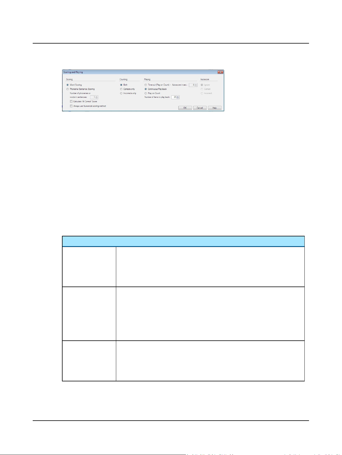
Scoring and Playing is a control where you can configure how to play back recordings and score the results. The control
contains four different columns as listed and described below. These columns present various controls, which you can combine to define how to run the test.
To set up word or phoneme scoring,
• click
or
• select Tools> Options> Speech> Scoring and Playing and click the pop-up button.
The Scoring and Playing dialog is shown.
Otometrics - AURICAL Aud
37
Page 38
2 Navigating in the OTOsuite Audiometry Module
The Scoring and Playing dialog
Word scoring
In word scoring you score either correct or incorrect responses using + or - in the Speech Player Panel.
Numerical phoneme/sentence scoring
In numerical scoring you click the numbered buttons in the Speech Player Panel to score the number of correct phonemes
in phoneme scoring or words in sentence scoring. The maximum score in a single presentation is either determined as a
fixed value (1 to 9 in the Scoring and Playing dialog) or automatically as determined by the integrated word list.
Specific phoneme/sentence scoring
Some speech materials support specific scoring. This means that you can click the scorable items directly in the speech list.
Scorable items can be either individual phonemes in phoneme scoring or individual words in sentence scoring.
You can use the All Correct button when the patient responds correctly to a presentation.
When you use specific phoneme scoring, you can keep your focus on the speech list by using the Play button next to the
item in the speech list.
Scoring
Scoring
Number of phonemes
or words in sentence
Calculate 'All Correct'
Score
Word scoring
Enable Word Scoring.
Phoneme/Sentence scoring
Enable Phoneme/Sentence Scoring.
Word scoring
Does not apply to word scoring.
Phoneme/Sentence scoring
Defines the total number of phonemes in the word. The default is 3 phonemes intended for
monosyllabic words. The corresponding number of buttons is enabled in the Speech Player
Panel, and on the Numerical pad of the PC keyboard.
Word scoring
Does not apply to word scoring.
Phoneme/Sentence scoring
Calculates all correctly scored phonemes or items based on
38 Otometrics - AURICAL Aud
Page 39
Scoring
2 Navigating in the OTOsuite Audiometry Module
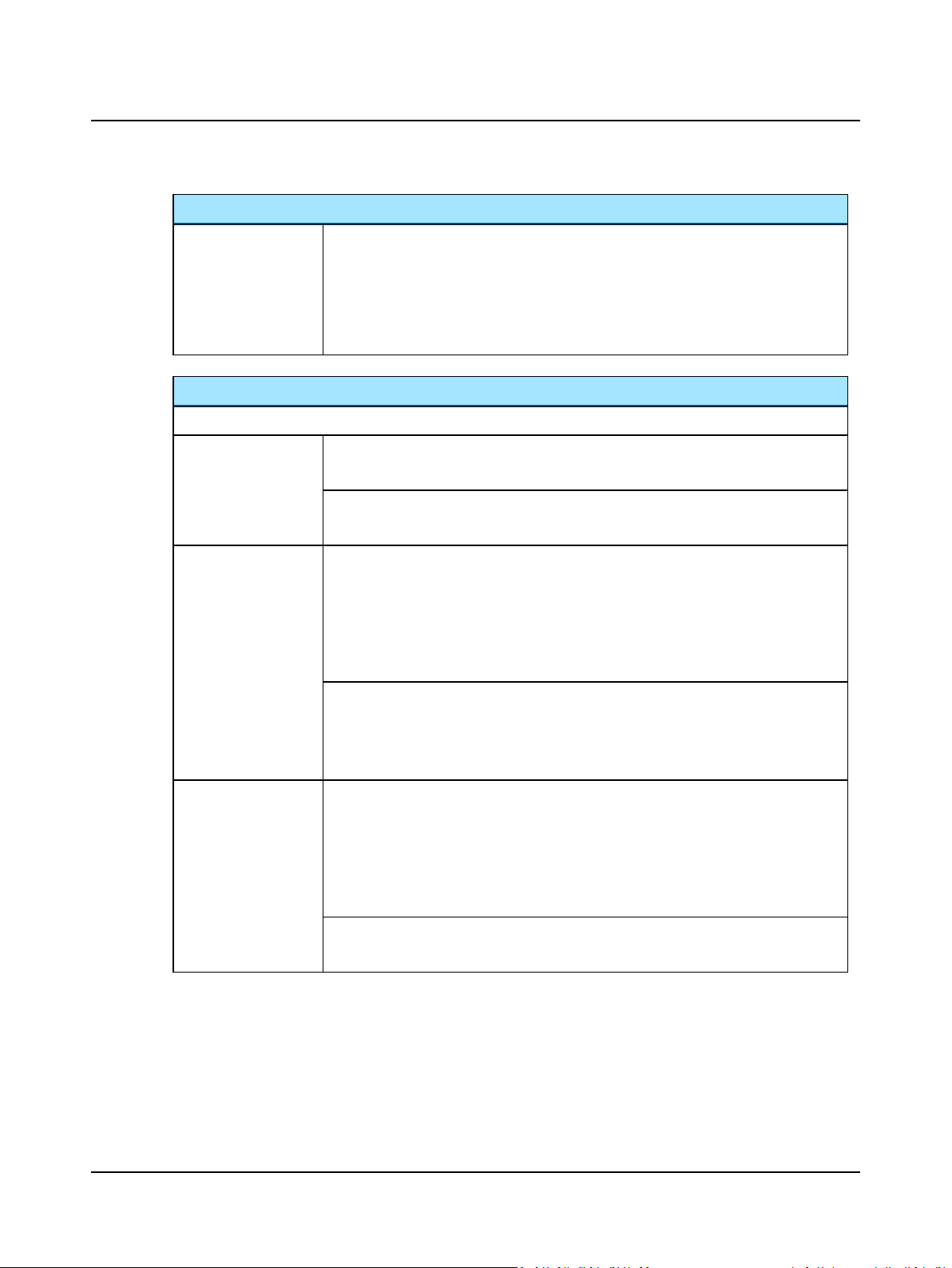
Always use Numerical
scoring method
Word scoring
Does not apply to word scoring.
Phoneme/Sentence scoring
Select this if you use lists using specific phoneme/sentence scoring, but prefer to score the
test items numerically.
Counting
Defines how you want to score words (Both, Corrects only and Incorrects only).
• Both
Word scoring
You manually score correct and incorrect words. The word counter is updated accordingly.
Phoneme/Sentence scoring
Does not apply to phoneme scoring.
• Corrects only
Word scoring
Software assumes the word is incorrect unless you manually score it as correct.
External speech material:
The percentage is calculated based on the total number of words you have defined in
advance - Tools> Options> Audiometry> Speech> Scoring and Playing> Number of
items to play back.
• Incorrects only
Phoneme/Sentence scoring
Score the number of correct phonemes using the corresponding numbers in the Counter.
External speech material:
Always enter a score for each word. This will update the counter accordingly.
Word scoring
Software assumes word is correct unless you manually score it as incorrect.
External speech material:
The percentage is calculated based on the total number of words you have defined in
advance - Tools> Options> Audiometry> Speech> Scoring and Playing> Number of
items to play back.
Phoneme/Sentence scoring
Does not apply to phoneme scoring.
Otometrics - AURICAL Aud
39
Page 40
2 Navigating in the OTOsuite Audiometry Module
Playing
Playing
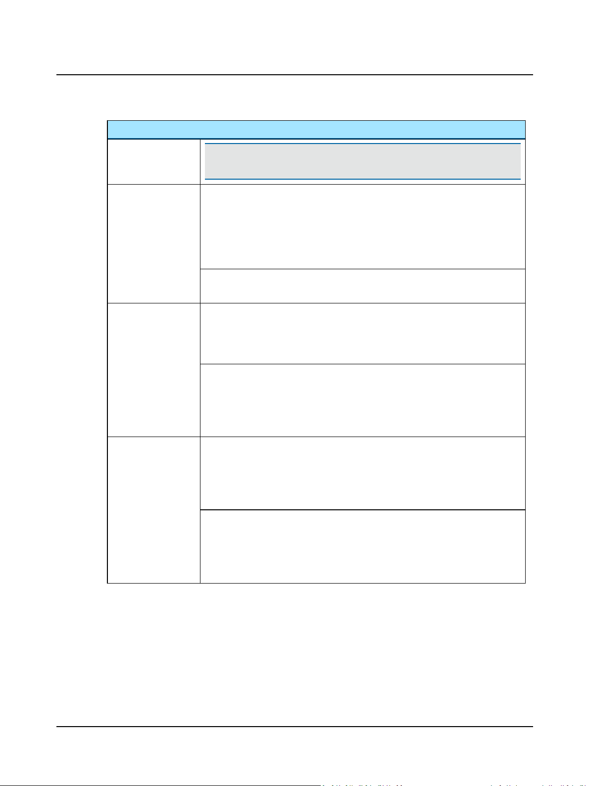
• Time-out (Play on
Count)
• Continuous Play-
back
Note•This feature applies to the playback of integrated word lists from the OTO-
suite Speech Material. It contains the following options:
Word scoring
Next word is presented every x seconds based on the value set in the Autoscore in sec box.
If the word is scored, the next word will be presented without pausing. If the current word
times out, the Autoscore is applied.
External speech material:
Does not apply to external sound source speech material.
Phoneme/Sentence scoring
Does not apply to phoneme scoring.
Word scoring
The word list is presented exactly as the original recording without pausing.
External speech material:
Does not apply to external sound source speech material.
Phoneme/Sentence scoring
The word list is presented exactly as the original recording without pausing. If a word is
presented without any phonemes being counted, the Autoscore is applied.
External speech material:
Does not apply to external sound source speech material.
• Play on Count
Word scoring
Next word plays after previous word is scored. To enable this option, select the value Both
under Counting.
External speech material:
Does not apply to external sound source speech material.
Phoneme/Sentence scoring
When the number of correct phonemes has been scored for a word, the next word is presented.
External speech material:
Does not apply to external sound source speech material.
40 Otometrics - AURICAL Aud
Page 41
Playing
2 Navigating in the OTOsuite Audiometry Module
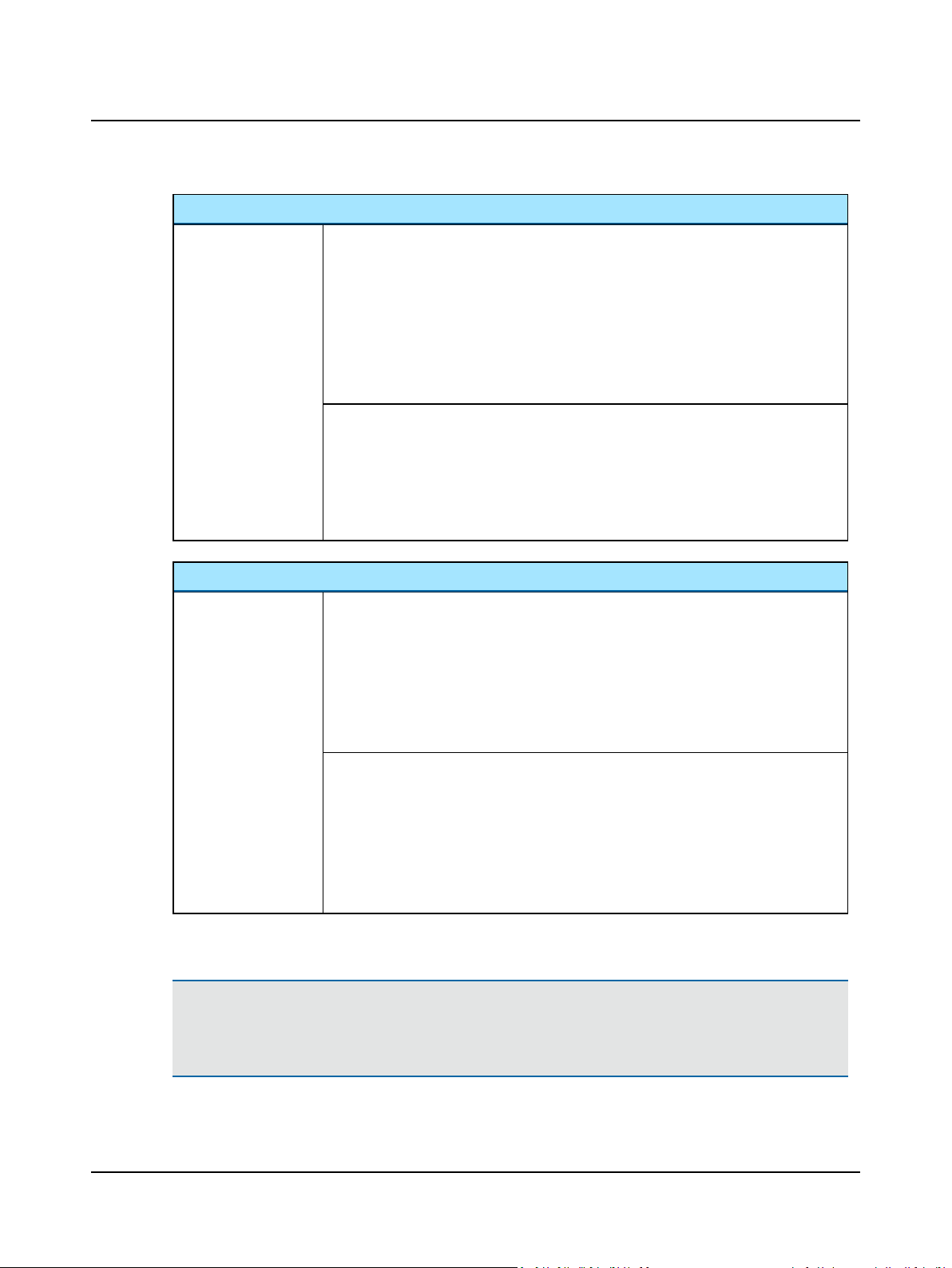
• Number of items
to play back
Autoscore
Autoscore
Word scoring
Defines the number of words to be presented from the integrated/external word list.
Integrated speech material:
The player pauses after presenting the defined number of words. Press Play to continue playing the rest of the list.
External speech material:
This is the total number on which the percentage should be based when counting Corrects
only or Incorrects only.
Phoneme/Sentence scoring
Defines the number of words to be presented from the integrated word list. The player
pauses after presenting the defined number of words. Press Play to continue playing the
rest of the list.
External speech material:
Does not apply to external sound source speech material.
Word scoring
When you score words, Autoscore is defined by the combinations of the settings in the
columns Counting and Playing.
If a word is not manually scored before Time-out or before the next word is presented by
Continuous Playback, the scoring is set automatically.
External speech material:
Does not apply to external sound source speech material.
Phoneme/Sentence scoring
When you score phonemes, you can define Autoscore manually to either ignore the entire
word, or count it as fully correct or incorrect.
If phonemes are not manually scored before Time-out or before the next word is presented
by Continuous Playback, the scoring is set automatically.
External speech material:
Does not apply to external sound source speech material.
2.9.2 Selecting speech material
Caution• Only speech material supplied on the OTOsuite Speech material CD is precalibrated according to the
description supplied with the original speech material.
If you use any other speech material, make sure that it is calibrated correctly.
Otometrics - AURICAL Aud
41
Page 42
2 Navigating in the OTOsuite Audiometry Module
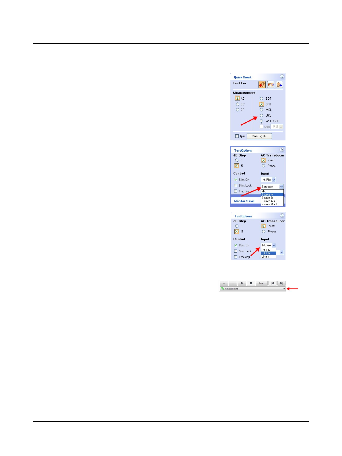
1. The speech measurement selection determines which type of speech
test will be stored.
2. Select speech input signals.
You can choose from either microphone input or pre-recorded input
sources. Combining Source A and Source B as Input sources in the Test
Options section of the Control Panel will replace the audiometer
speech masking with a recorded input.
3. Select speech input from pre-recorded input sources for Source A or
Source B from the drop-down lists in the Test Options section of the
Control Panel.
– Int. CD (CD material in CD/DVD drive)
– Int. File (integrated OTOsuite Speech Material or regular sound
files)
– Line In (analog input from external sound players, eg. CD, MD, MP3
or cassette recorders connected to the audiometer via the Line In
input).
4. You can find the speech material files in the File/track/list selection
drop-down list.
Speech list files (provided by Otometrics)
When you use integrated OTOsuite Speech Material, you can choose between speech lists in the File/track/list
selection drop-down list.
• Select Int. File in the Control Panel, and browse to the folder where your speech material is installed (default
location: c:\ Program Files\GN Otometrics\OTOsuite\Wordlists\...).
Regular sound files (files not supplied on the OTOsuite Speech Material CD)
You can use any sound file stored on your PC hard drive:
• Select Int. File in the Control Panel, and browse to the folder where your recordings are stored.
42 Otometrics - AURICAL Aud
Page 43
CD material
You can use any type of CD sound recordings of your choice.
• Select Int. CD in the Control Panel, and browse to the drive you wish to use.
These files are shown as CD track numbers in the File/track/list selection drop-down list.
Line In
When Line In is selected, only the Counter of the Player Panel is activated.
2.9.3 Scoring words using integrated OTOsuite Speech Material
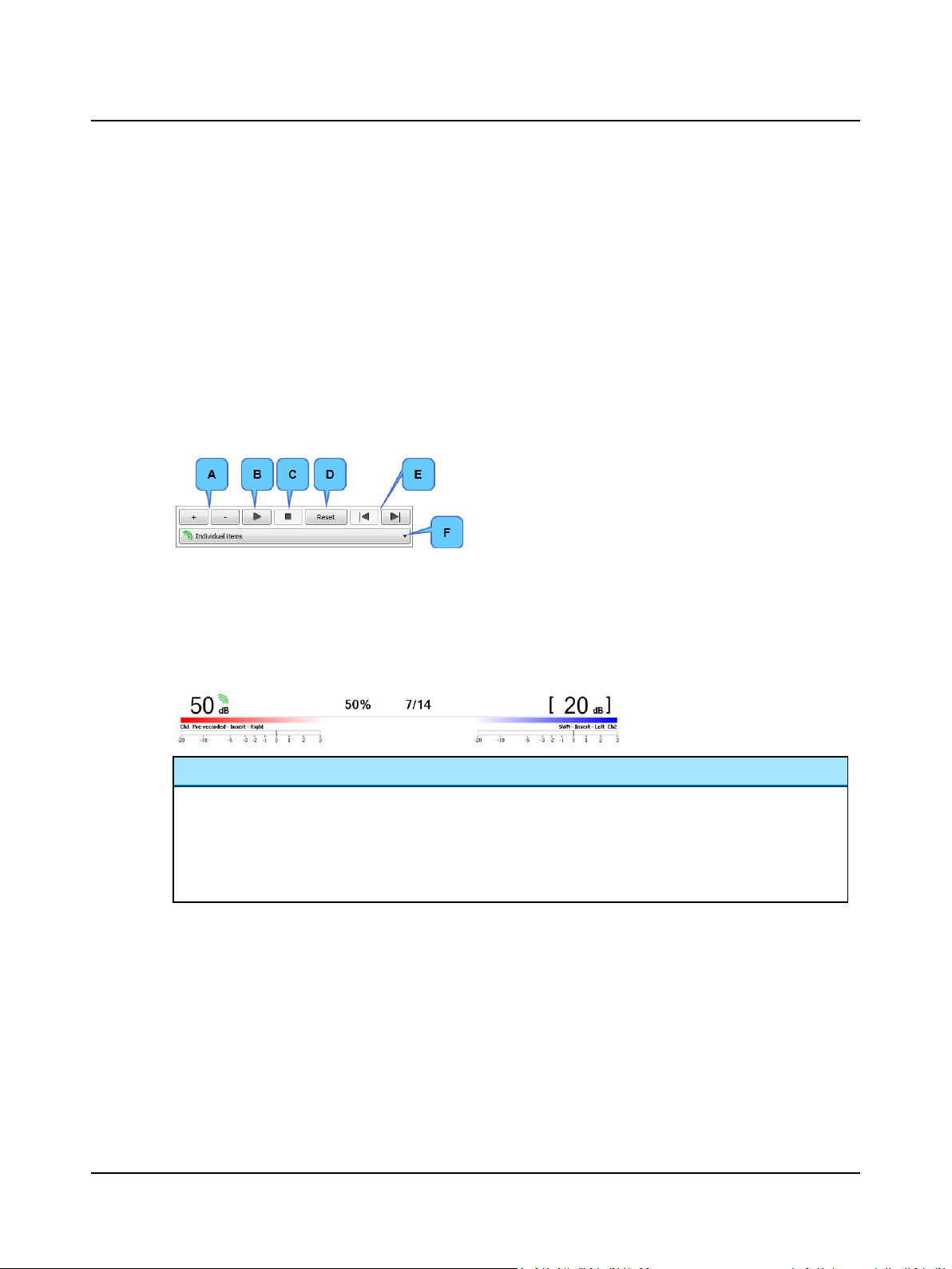
The Speech Player Panel
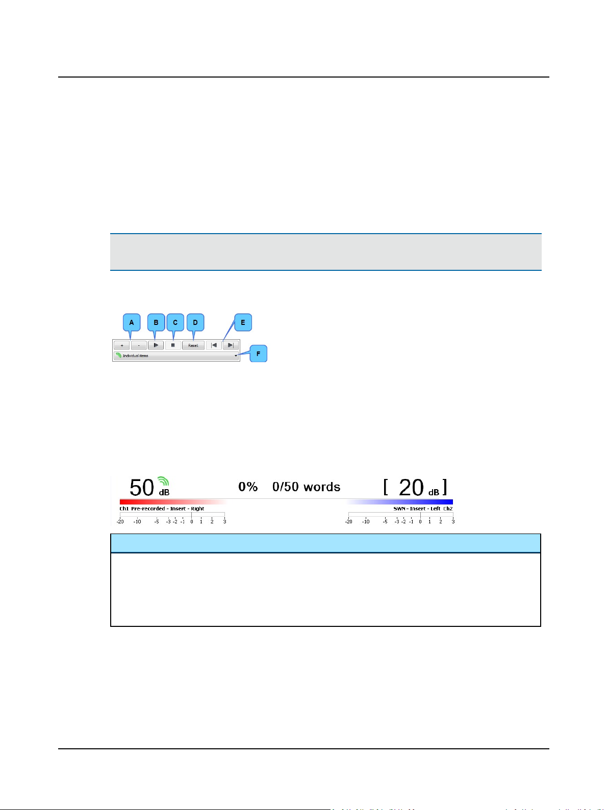
A. Word score counter buttons:
Correct (+)
Incorrect (-)
B. Play/Pause
C. Stop
D. Reset word score
E. Previous/next list
F. File/track/list selection
2 Navigating in the OTOsuite Audiometry Module
Setting up for Scoring and Playing
To set up for scoring and playing, see Selecting word or phoneme scoring ► 37.
The Stimulus bar - word score
Scoring Panel
The score percentage and the Correct or Incorrect scores relating to the number of words played are shown at the top
of the screen.
When you use integrated word lists, the Scoring Panel is either initialized to "0% 0/0" or to “100% 0/0”, depending on
the setting in Tools> Options> Audiometry> Speech> View> Score Presentation.
• Click on the relevant Word score counter button to record the response of the client.
Otometrics - AURICAL Aud
43
Page 44
2 Navigating in the OTOsuite Audiometry Module
The Word List box
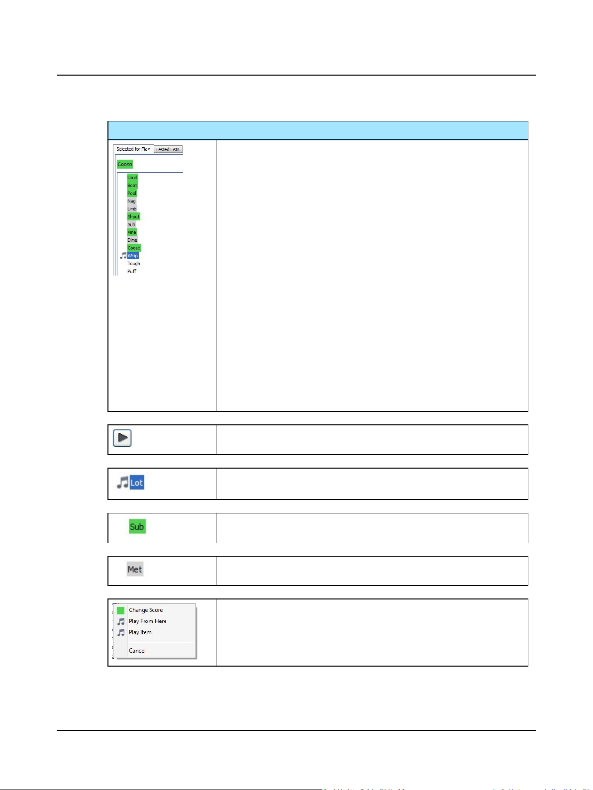
The Word List box consists of a tab showing the list Selected for Play, and Tested Lists.
Selected for Play
The Word List is shown automatically in the Selected for Play tab, when you select an
integrated word list.
You can view the selected OTOsuite Speech Material in the Word List, and use it to
review and edit scoring during the test.
Scoring
You can always click on any word to change the score.
The word that has just been played is also shown above the list so that you can easily
score it.
• Specific scoring:
• Numerical scoring:
Tested Lists
After you have scored the integrated word lists they will appear in the Tested Lists tab.
The Tested Lists tab will show the list belonging to the test currently selected in the
Speech Results table (tabular) or Speech legend (graphical). The tested lists are also available for printing.
Click on the word to toggle between Correct, Incorrect. or Not Scored,
or
Use the traditional score controls (+/- for word scoring, or 0, 1, 2, 3... for phoneme
and sentence scoring) in the Player Panel.
When you mouse over an item in the speech list, a Play button appears to the left of
the item. Click the Play button to present the item to the patient.
The word currently playing is indicated by a musical note and highlighted in blue in the
list.
A word that was correctly repeated is highlighted in green in the list.
A word that was incorrectly repeated is highlighted in gray in the list.
• You can right-click on a word to change the score or control the play-back of the
word list.
• You can either play back a single item or select a place in the list where you want
to start the play-back.
44 Otometrics - AURICAL Aud
Page 45
Using word lists with monitored live voice testing
When you have loaded an integrated OTOsuite Speech Material, you can use the word list to read from using Mic. stimulus, for live voice testing.
Store the word scores
See Storing speech data ► 37.
2.9.4 Scoring words using external sound source
Note•Using an external sound source includes the use of all types of sound sources such as CDs, MP3 players,
cassette recorders, and sound files on the PC hard drive except for the integrated OTOsuite Speech Material.
The Speech Player Panel
2 Navigating in the OTOsuite Audiometry Module
A. Word score counter buttons:
Correct (+)
Incorrect (-)
B. Play/Pause
C. Stop
D. Reset word score
E. Previous/next list
F. File/track/list selection
(disabled when Line In is selected)
Setting up for Scoring and Playing
To set up for scoring and playing, see Selecting word or phoneme scoring ► 37.
The Stimulus bar - word score
Scoring Panel
The score percentage and the Correct or Incorrect scores relating to the number of words played are shown at the top
of the screen.
When you use external word lists, the Scoring Panel is either initialized to "0% 0/n" or to “100% n/n”, depending on
the setting in Tools> Options> Audiometry> Speech> View> Score Presentation.
• Click on the relevant Word score counter button to record the response of the client.
Store the word scores
See Storing speech data ► 37.
Otometrics - AURICAL Aud
45
Page 46
2 Navigating in the OTOsuite Audiometry Module
2.9.5 Scoring phonemes using integrated OTOsuite speech material
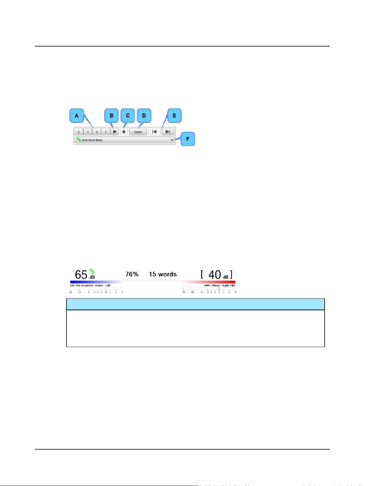
The Speech Player Panel
A. Phoneme score counter buttons:
No correct phonemes (0)
1 phoneme correct (1)
2 phonemes correct (2)
All 3 phonemes correct (3)
B. Play/Pause
C. Stop
D. Reset Counter scoring and Player
E. Previous/next list
F. File/track/list selection
In the Speech Player Panel example shown above, the Number of phonemes setting in the Scoring and Playing dialog
box is set to 3.
Configurable number of phonemes
The integrated speech materials dictate the number of phonemes and provide the appropriate number of scoring buttons
automatically. This can be configured specifically for each item in the integrated Speech material. Please contact your supplier for further information.
Setting up for Scoring and Playing
To set up for scoring and playing, see Selecting word or phoneme scoring ► 37.
The Stimulus bar - phoneme score
Scoring Panel
The score percentage and the number of words played are shown at the top of the screen.
The Scoring Panel is either initialized to "0% 0 words" or to “100% 0 words”, depending on the setting in Tools>
Options> Audiometry> Speech> View> Score Presentation.
• Click on the relevant phoneme score counter button to record the response of the client.
46 Otometrics - AURICAL Aud
Page 47
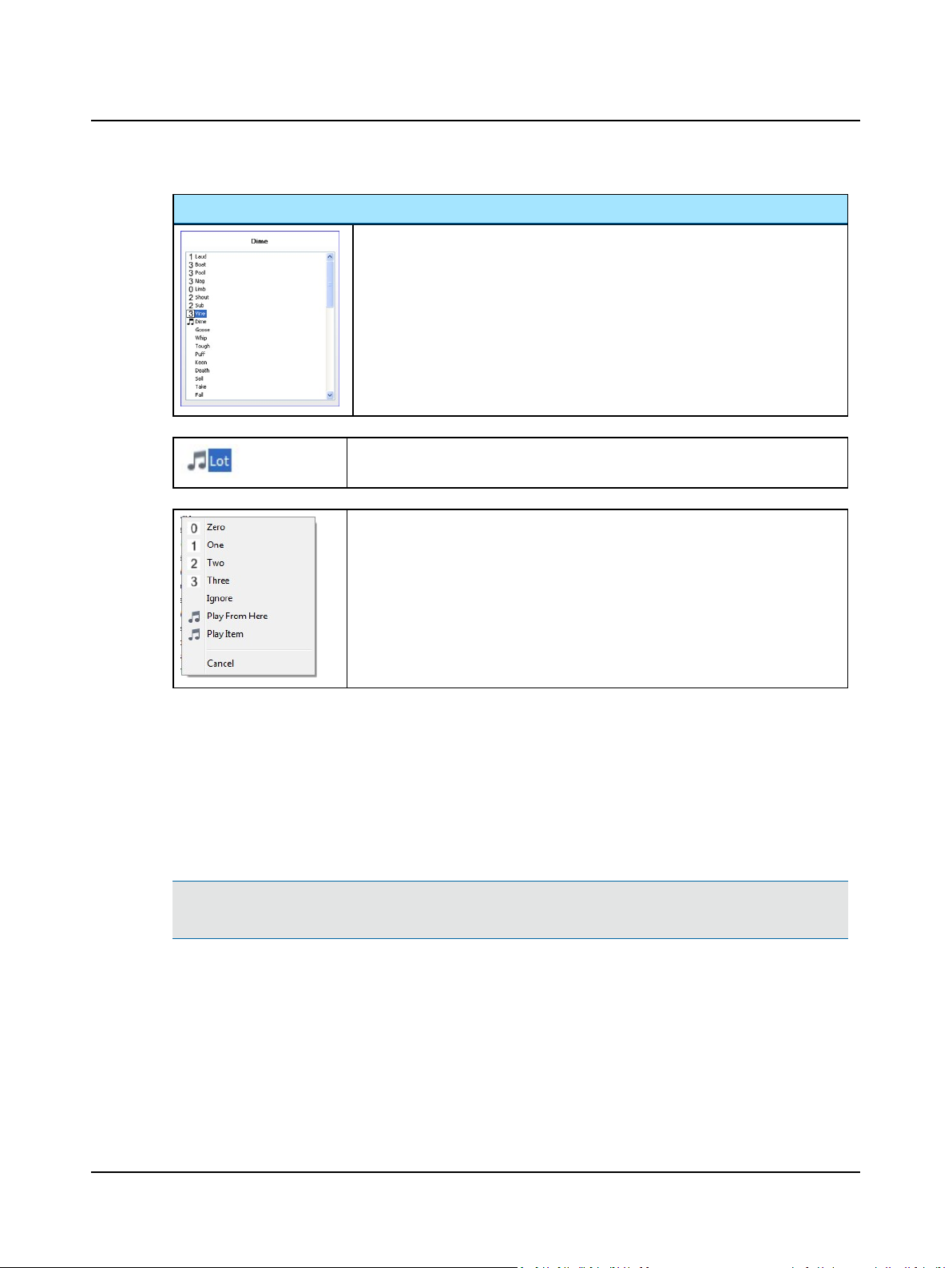
The Word List
2 Navigating in the OTOsuite Audiometry Module
The Word List is shown automatically when you select an integrated word list.
You can view the currently selected integrated OTOsuite Speech Material in the Word
List, and use it to review and edit scoring during the test. You can also see the word
currently being played back for monitoring purposes.
The number of correct phonemes repeated is marked with the corresponding number
to the left of the word in the list.
The word currently playing is indicated by a musical note and highlighted in blue in the
list.
• You can right-click on a word to change the score or control the play-back of the
word list.
• You can either play back a single item or select a place in the list where you want
to start the play-back.
Using word lists with monitored live voice testing
When you have loaded an integrated OTOsuite Speech Material, you can use the word list to read from using Mic. stimulus, for live voice testing.
Store the phoneme score results
See Selecting the work area in the Speech screen ► 36.
2.9.6 Scoring phonemes using external sound source
Note•Using an external sound source includes the use of all types of sound sources such as CDs, MP3 players,
cassette recorders, and sound files on the PC hard drive except for the integrated OTOsuite Speech Material.
Otometrics - AURICAL Aud
47
Page 48
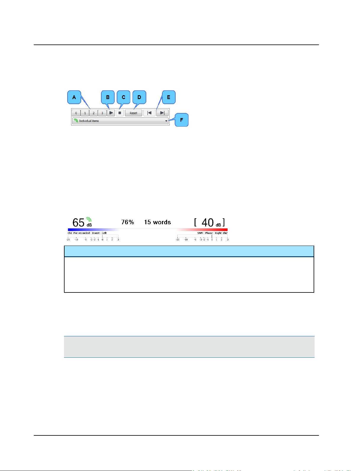
2 Navigating in the OTOsuite Audiometry Module
The Speech Player Panel
In the Speech Player Panel example shown above, the Number of phonemes setting in the Scoring and Playing dialog
box is set to 3.
Setting up for Scoring and Playing
To set up for scoring and playing, see Selecting word or phoneme scoring ► 37.
The Stimulus bar - phoneme score
A. Phoneme score counter buttons:
No correct phonemes (0)
1 phoneme correct (1)
2 phonemes correct (2)
All 3 phonemes correct (3)
B. Play/Pause
C. Stop
D. Reset Counter scoring and Player
E. Previous/next list
F. File/track/list selection
(disabled when Line In is selected)
Scoring Panel
The score percentage and the number of words played are shown at the top of the screen.
The Scoring Panel is either initialized to "0% 0 words" or to “100% 0 words”, depending on the setting in Tools>
Options> Audiometry> Speech> View> Score Presentation.
• Click on the relevant phoneme score counter button to record the response of the client.
Store the phoneme score results
See Selecting the work area in the Speech screen ► 36.
2.9.7 Saving source levels for speech material
Note•This feature applies to sound files on the PC hard drive except for the integrated OTOsuite Speech Mater-
ial.
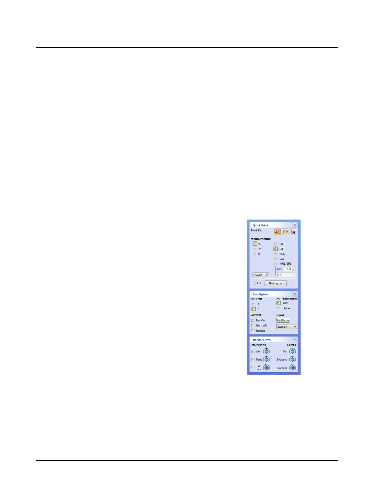
If you have a folder on the PC containing WAVE (.wav) files, eg. from a CD, you can calibrate these files by adjusting the
Source A and Source B levels in the Monitor and Level section of the control panel. The next time you browse to this
folder (or create a user test) the Source A and Source B level settings will automatically be set to the saved level.
48 Otometrics - AURICAL Aud
Page 49
Procedure
1. Browse to the folder containing the WAVE (.wav) file or files you wish to adjust to a specific level.
2. Play the calibration file from the Speech player.
3. Use the dials in the Monitor and Level section of the control panel to adjust the levels to zero, as seen on the VU
meter.
4. Open the Play list in the Speech player and click Save Source A & B level in this folder.
5. A file called "0.speechlevel" is created in this folder.
The next time you play any file from this folder, it will be calibrated to the level set in the "0.speechlevel" file.
2.10 Speech testing - tabular view
Selecting tabular or graphical view
In the Speech test screen of the OTOsuite Audiometry module you can use either tabular view or graphical view.
1. To select the view you wish to use, select Tools> Options> Audiometry> Speech> Speech View Mode> Tabular
View or Graphical View.
2 Navigating in the OTOsuite Audiometry Module
AURICAL Aud is intended for use with predefined speech protocols
that are loaded automatically when you select a user test.
You can have a full overview and instantly select measurement
type, ear, transducer, stimulus type, routing, and speech material.
• If you wish to make manual changes on the fly, use the control
panel to select.
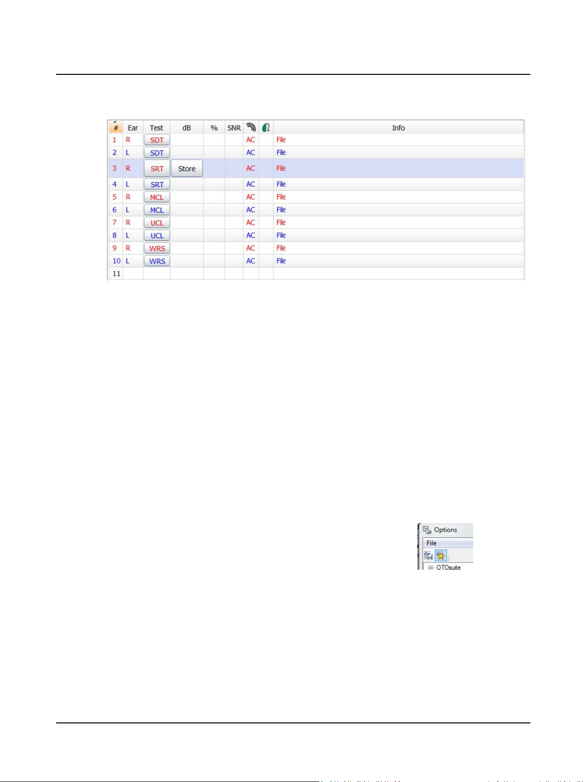
The predefined tests are incorporated as rows in the speech table.
• To select a predefined test, simply click the button in the Test colum. This will load all the speech settings and speech
material.
Otometrics - AURICAL Aud
49
Page 50
2 Navigating in the OTOsuite Audiometry Module
If you perform a test which is not available in a predefined Speech table, a speech row is created automatically. This temporary row will exist as long as there is stored test data for that measurement setup.
2.10.1 Creating and editing the speech test table
You can create the speech test table if a predefined test is not available, or if you wish to change settings on the fly.
1. Select ear, transducer, stimulus type, routing, test type, and speech material.
2. To permanently add the test row to the table, you must
– pin it to the table,
– save it to a user test.
Pinning the test
You can pin one or several rows to the table,one by one. To do so, right-click the active row in the speech table,
select Configure > Pin Test.
When you have pinned the test row to the table, you can change the order of the pinned tests. To do so, right-click
the active row in the speech table, select Configure > Move Up/Move Down.
You can also assign a different speech material or stimulus source. To do so, make your stimulus selection, right-click
the active row in the speech table, and select Configure > Assign selected stimulus.
Saving the table to a user test
When you have pinned the new test rows to the speech table, you
must save it to a user test or to your start-up settings.
Open the Tools > Options dialog and click to save as a user test or as
start-up settings.
Saving different speech tables to specific user tests has several benefits:
• You can have identical test setups, but use different speech materials for different patient groups (e.g. different languages, pediatric materials)
• You can use different test setups depending on the task (e.g. diagnosis/hearing aid verification)
You can load and include several different speech tables when you test a patient. Rows with no data will be discarded
(right-click in the row to select Did not test or Could not test if you wish to retain blank rows before you load additional
user tests).
50 Otometrics - AURICAL Aud
Page 51
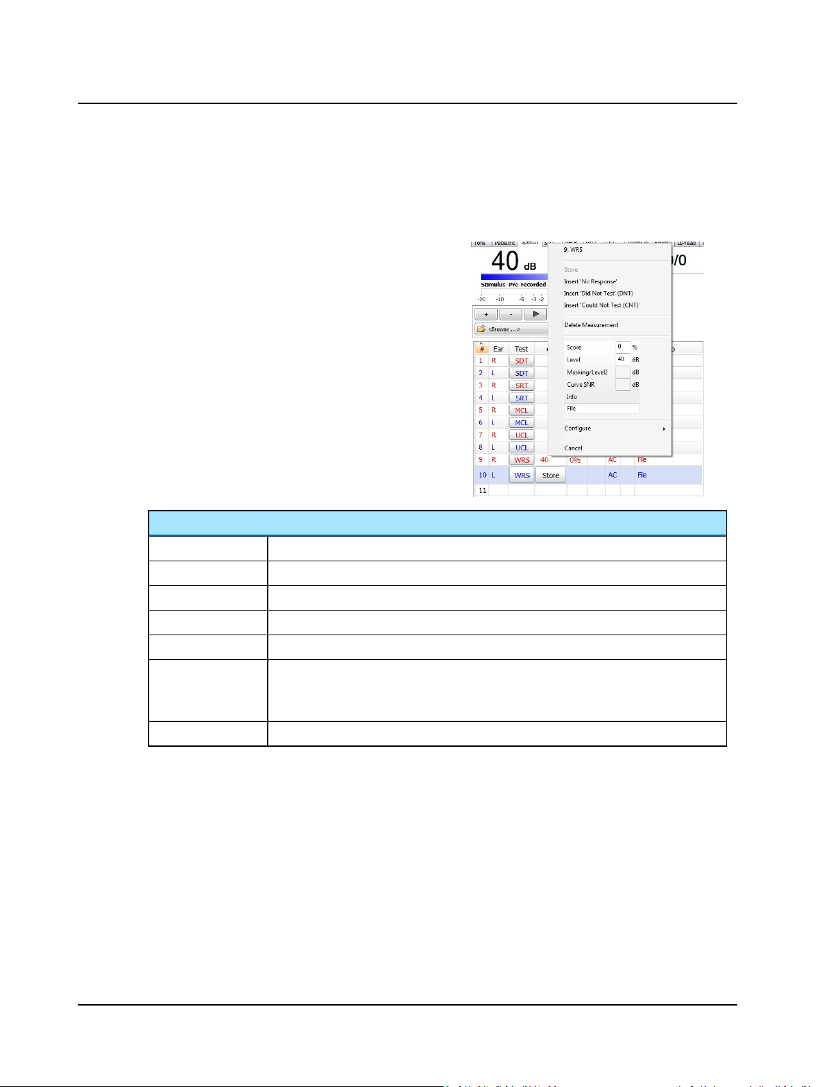
If you do not use any predefined tests, you must select all settings and speech material manually. Rows will then automatically be added and you retain them in the table by storing the result.
2.10.2 Speech editing options - tabular view
When you right-click any of the rows in tabular view, the following options appear:
2 Navigating in the OTOsuite Audiometry Module
Options
Store
Insert No Response
Insert Did Not Test
Insert Could Not Test
Delete Measurement
Entry fields
Stores the dB level(s) currently displayed to the field that is highlighted.
NR will replace the stimulus level for the selected speech test.
DNT will replace the stimulus level for the selected speech test.
CNT will replace the stimulus level for the selected speech test.
Deletes an existing measurement.
Enables you to enter results in the selected field.
• When you have typed in the desired data, confirm by pressing Enter or cancel by pressing
Esc.
Configure See Creating and editing the speech test table ► 50.
Editing a row
Click on the data you wish to edit and use the right-click menu to change the value.
Deleting a row
Right-click on the field you wish to delete and select Delete Measurement.
Sorting the tabular speech data
You can sort your data either by ear or by its sequential number depending on your needs. Usually, the sequential sorting
is preferred during data collection when you perform one test type at a time. Sorting by ear is sometimes preferred when
you compare the ears when analyzing the complete results.
• To sort data by their sequential number, click the number field in the table header (marked with the #symbol).
Otometrics - AURICAL Aud
51
Page 52
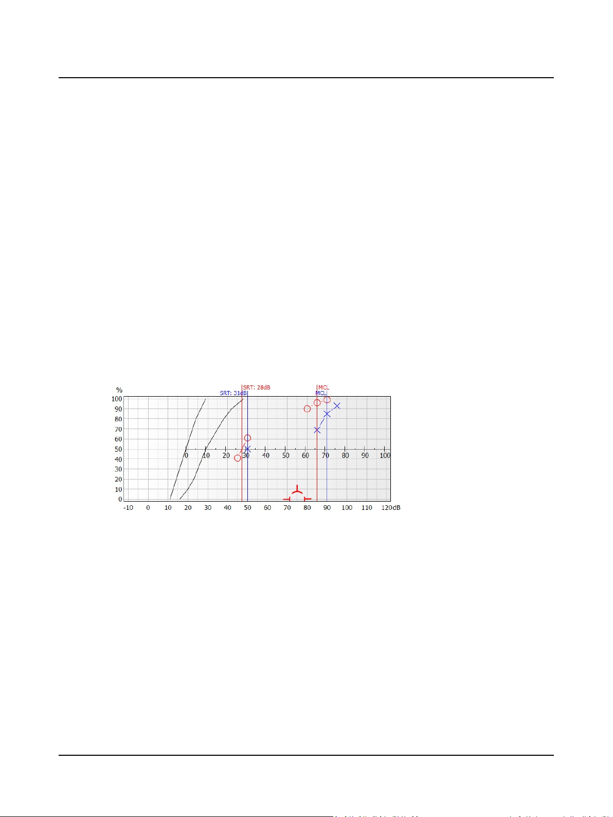
2 Navigating in the OTOsuite Audiometry Module
• To sort data by ear, click the ear field in the table header.
The Info field
The Info field provides additional information such as a stimulus source (e.g. CD, Live, File, or specific speech material), as
well as noise condition, and your own comments if desired. To add your own comments, right-click the Info field.
2.10.3 Storing SNR for Speech testing
Word and Sentence Recognition tests can be performed in noise. The Signal to Noise Ratio can be stored with the data
regardless of whether the noise comes from the recording or is generated in the audiometer.
You can enter an SNR manually or set it to be calculated automatically based on the difference between the Stimulus and
the noise channel levels.
• Manual:
is useful when signal and noise are mixed together in the speech recording.
• Automatic:
is useful when you mix speech and noise from the two audiometer channels.
2.11 Speech testing - graph view
General description
The Speech Graph screen displays the speech graph which includes SDT, MCL, UCL noted by a line (blue = left, red = right)
at the corresponding dB level.
For SRT and WRS/SRS, or WRS/SRS with noise, symbols will be shown based on the location corresponding to the dBlevel
of presentation and the percentage of correct responses.
The graphical speech legend
The graphical speech legend shows the measurement conditions for testing and displays the corresponding symbols from
the graph. The legend rows are color coded according to their respective routing.
The legend adapts to the tests and adds a row for each measurement you make. You can also pin tests so that they are
readily available for future testing.
Adaptive rows
The rows in the adaptive legend always show the current measurement settings and the measurements you have made. A
new row will be added to the legend every time you make a new test.
52 Otometrics - AURICAL Aud
Page 53
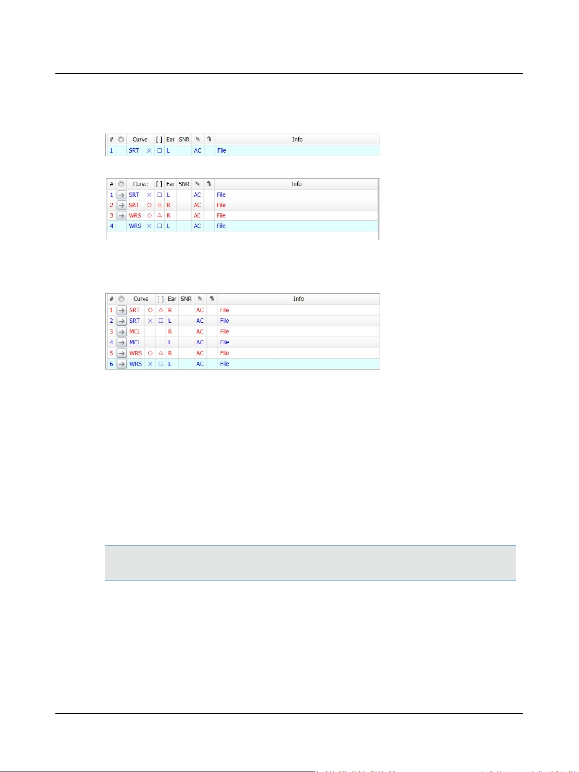
2 Navigating in the OTOsuite Audiometry Module
Example
The adaptive Speech legend showing the current measurement settings. Data has not been stored at this point.
The adaptive Speech legend showing the three first measurements followed by a blank row with the current measurement
settings ready to be stored.
Pinned rows
You can pin a row to make it available in advance in order to reflect the measurements usually performed in your clinic. A
legend with pinned rows will always look the same when you start testing a new patient.
This customized layout provides you with a consistent work environment and makes it easy to see what to do next, or if
any test has been deliberately left out.
A test that is not pinned to the legend is added automatically below the pinned rows.
Click 'n' Get
The Click 'n' Get feature allows you to perform a test from the predefined legend simply by clicking the Apply Settings
arrow button in the second column of the legend. Click 'n' Get loads all the relevant settings including the integrated
speech files.
Pinning a test
You can pin one test per measurement condition.
Note•You can pin a test to the legend, if you have not already pinned an identical test. To edit a pinned test,
make sure that User Tests are not write protected in the Configuration Wizard.
To pin a row, simply select the row, right-click and select Pinned Tests> Pin Test. Here you can also rearrange pinned
rows by moving them up or down in the legend.
Modifying Click 'n' Get for a pinned test
You can assign a different speech stimulus and/or transducer to a pinned test. This will load the desired word list, transducer, etc., when you use the Click 'n' Get feature.
Otometrics - AURICAL Aud
53
Page 54

2 Navigating in the OTOsuite Audiometry Module
Changing assigned speech stimulus for a pinned test
1. Select the speech stimulus, such as a specific integrated word list, or internal CD or line-in device, in the Control Panel
and/or speech player.
2. Right-click on the Apply Settings button in the pinned test row, and select Assign Selected Stimulus.
Changing an assigned transducer for a pinned test
1. Select the transducer in the Control Panel.
2. Right-click on the Apply Settings button in the pinned test row, and select Assign Selected Transducer.
Note•When you use Click 'n' Get to apply settings, the AC transducer as well as the speech stimulus are loaded
as your preferred starting point. You can always adjust them in the Control Panel or in the Speech Player panel.
Example 1:
You typically use insert phones but you have a patient with an ear infection and you wish to use supra-aural headphones. Use Click 'n' Get to load the desired test, and simply switch to Phone in the Control Panel before you
start the test.
Example 2:
You typically wish to start the Speech test by familiarizing the patient with a specific word list before starting the
actual test with a different word list. Use Click 'n' Get to load the desired starting point, and simply switch to any
word list you wish to use after the familiarization.
Storing data in a row
To store data in a row, click the dB field in the relevant row or press S on your keyboard.
The Info field
The Info field provides additional information such as a stimulus source (e.g. CD, Live, File, or specific speech material), as
well as noise condition, and your own comments if desired. To add your own comments, right-click the Info field.
Editing a row
Click on the data you wish to edit and use the right-click menu to change the value.
Deleting a row
Right-click on the field you wish to delete and select Delete Measurement.
2.11.1 Speech editing options - graph view
When you right-click on a measurement in the graph, the following options appear:
Options
Selected Point (e.g. WRS, Left,
Live, AC)
Delete Point
If more than one symbol is at the same %/intensity, select the data point of interest
from the drop down.
Deletes a selected data point.
54 Otometrics - AURICAL Aud
Page 55
Options
2 Navigating in the OTOsuite Audiometry Module
Delete Curve
Insert No Response
Insert Did Not Test
Insert Could Not Test
%
All Correct score
Level
Masking/Level2
Curve SNR
When you right-click on a row in the graph legend, the following options appear:
Deletes a selected data curve.
This will overwrite the current symbol with a No Response symbol.
This will overwrite the current symbol with a Did Not Test symbol.
This will overwrite the current symbol with a Could Not Test symbol.
If needed, change the score.
Is shown if
log.
If needed, change the level.
Displays the effective masking level of the measurement point (dB EML).
Displays the Signal to Noise ratio used for the entire curve (SNR).
Calculate 'All Correct' Score
is enabled in the
Options
Selected Point (e.g. WRS, Left, Live, AC)
Info
Identifies the curve in the graph that you wish to edit.
If needed, enter information of your choice.
Scoring and Playing
dia-
2.12 Speech feature boxes
You can access a number of speech display options directly from the Speech main screen.
Feature boxes
Pure Tone Data
Displays the pure tone average for air conduction and bone conduction as well as the articulation
index.
• To configure pure tone average (PTA) calculation, select Tools> Options> Audiometry> Gen-
eral> Misc.> PTA Frequency AC/BC.
• The AI is calculated according to the “Count-the-dot” method.
Stenger
Displays the results of a speech Stenger test (optional).
• Scoring options are positive (+) or negative (-).
2.13 Terms and abbreviations used in Speech testing
SDT
SRT
Otometrics - AURICAL Aud
Speech Detection Threshold
Speech Recognition Threshold
55
Page 56

2 Navigating in the OTOsuite Audiometry Module
MCL
UCL
WRS/SRS
PTA
AI
Most Comfortable Loudness Level
UnComfortable Loudness Level
Word Recognition Score/Sentence Recognition Score
• Score
Percentage of correct/incorrect words.
• Level
dB level at which the words were presented.
• [Msk]
Effective masking level (dB EML) used for contralateral masking.
• SNR
Signal-to-Noise Ratio.
Pure Tone Average
• PTA - AC
Pure Tone Average for Air Conduction thresholds.
• PTA - BC
Pure Tone Average for Bone Conduction thresholds.
Articulation Index (%), based on the Count-the-dot method.
56 Otometrics - AURICAL Aud
Page 57
2.14 Special tests
2.14.1 SISI (Short Increment Sensitivity Index)
The SISI Test was developed by Jerger and co-workers (Jerger, Shedd, and Harford, 1959) and was introduced as a procedure that was reliable and reasonably objective.
The test consists of superimposing brief bursts of 1dB intensity increments on a sustained tone presented monaurally
through earphones at a sensation level of 20dB at each tested frequency.
The patient is instructed to report any jumps in loudness detected while listening to the sustained tone for a period of
about two minutes.
2.14.1.1 Navigating in SISI
The Control Panel
Channel
Continuous On
Transducer
Insert
Phone
High Frequency
Routing
Left
Right
Test Options - SISI
Transducer
dB Step
SISI dB Step
When checked, the stimulus will be continuously on and will turn off when you press the stimulus button.
Presents the stimulus through the insert earphones.
Presents the stimulus through the headphones.
Presents the stimulus through the high frequency headphones.
Stimulus is routed to the left transducer.
Stimulus is routed to the right transducer.
This determines the dB step size for the intensity of the stimulus when presenting the tone
manually. Options are 1, 2, and 5.
This determines the dB step size for the intensity of the stimulus when presenting the tone
automatically using the play button. Options are 1 (should be used for testing), 2, and 5.
Otometrics - AURICAL Aud
57
Page 58
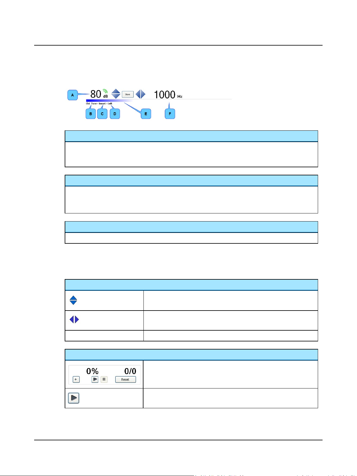
2 Navigating in the OTOsuite Audiometry Module
SISI Stimulus Bar
Intensity
Indicated by the dB level above the channel status bars.
• The green wave symbol above the level indicates with two waves that the stimulus carrier tone is currently being
presented, and with three waves that the increment is applied.
Stimulus bar color
Indicates the routing for the channel:
• Blue = left ear
• Red = right ear
A. Intensity
B. Stimulus indicator
C. Transducer indicator
D. Routing indicator
E. Stimulus bar color
F. Frequency
Stimulus, transducer and routing indicators
Indicates the stimulus type, the transducer and the routing for each channel.
Test controls
Test controls provide a means of operating the audiometer if you use the mouse and on-screen options to perform tests.
• To enable test controls, select Tools> Options> Audiometry> General> On-screen controls.
Controlling intensity and frequency, and storing data
• The Arrow up button increases the intensity.
• The Arrow down button decreases the intensity.
• The Arrow left button decreases the stimulus frequency.
• The Arrow right button increases the stimulus frequency.
Store
Scoring Level Intensity Change Recognition
• Stores the data point.
• Click the + button each time the patient acknowledges that a change in
intensity was heard
• Play button
Starts the test.
58 Otometrics - AURICAL Aud
Page 59
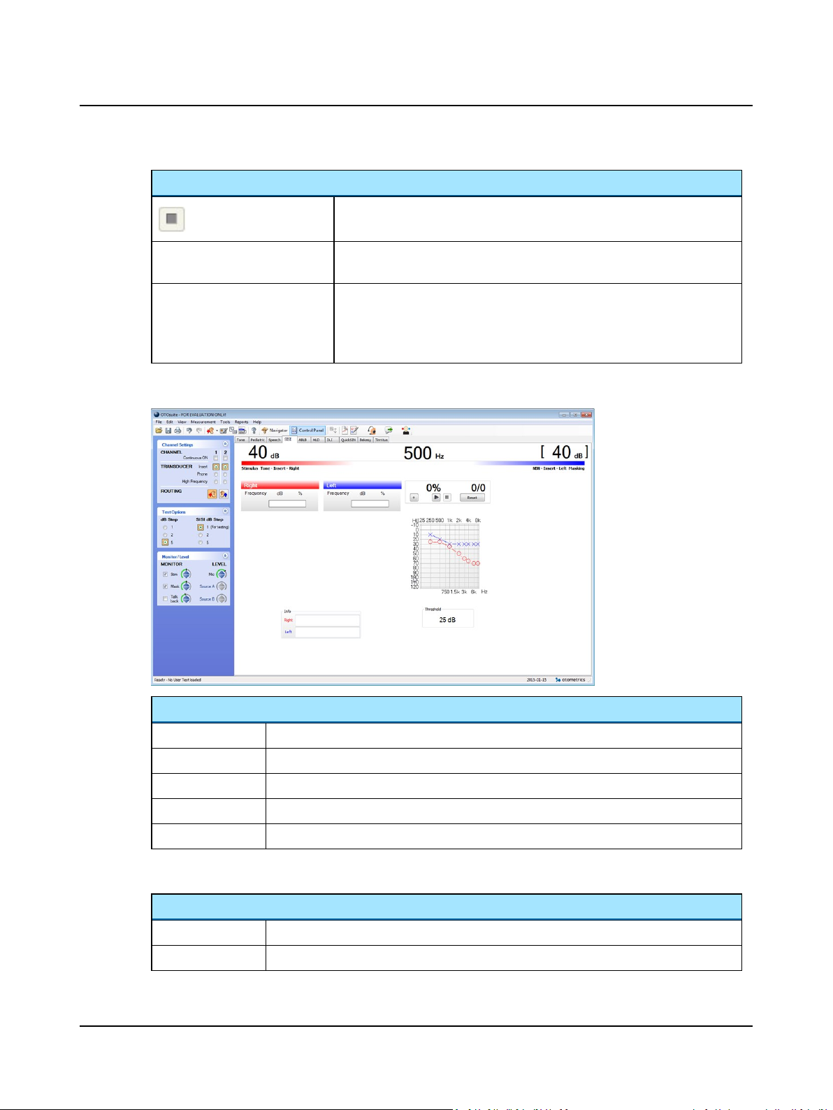
Scoring Level Intensity Change Recognition
• Stop button
Stops the test.
Reset • Reset button
Resets the score to 0% and 0/0.
The score box tracks the number of 1dB intensity changes presented and the
number of 1dB intensity changes the patient heard.
The percentage is a ratio of the number of intensity changes heard compared to
the number of intensity changes presented.
SISI data
2 Navigating in the OTOsuite Audiometry Module
Data display in SISI screen
Frequency
dB
%
Audiogram
Threshold
SISI editing options
Editing options
Delete
Delete all
Otometrics - AURICAL Aud
• The frequency which was presented.
• The intensity.
• The score.
• Displays pure tone audiogram.
• Displays pure tone average.
• Deletes the data for a particular frequency for a particular ear.
• Deletes the data for all the frequencies for a particular ear.
59
Page 60
2 Navigating in the OTOsuite Audiometry Module
2.14.1.2 The test process - SISI
The audiometer produces an intensity increment every 5seconds. Each increment has a rise time of 50msec, a duration
at full strength of 200 msec, and a decay time of 50 msec. The size of the increment can be varied from 0 to 5dB in 1dB
steps (selected on-screen from the Increment box), although the test is scored only on the percentage of 1dB increments
correctly identified by the patient. Twenty 1dB increments are presented during the test. If the subject responds 10
times out of the 20 1dB increments, the sensitivity index is 50%.
Before starting the test
Before starting the test, present five 5dB increments to give the patient a noticeably intense increment to respond to.
2.14.2 ABLB (Alternate Binaural Loudness Balance)
This test was first described by Fowler (1928).
Hearing levels at which a pure tone sounds equally loud to both ears of a subject are compared.
The test is applicable when there is a difference in hearing loss of at least 20dB between the two ears at the pure-tone
test frequency.
2.14.2.1 Navigating in ABLB
The Control Panel
Channel
Continuous On
Transducer
Insert
Phone
High Frequency
Routing
Left
Right
Test Options - ABLB
Transducer
dB Step
ABLB dB Step
This determines the dB step size for the intensity of the reference stimulus tone. Options are 1, 2,
and 5.
This determines the dB step size for the intensity of the ABLB test stimulus. Options are 1 (should be
used for testing), 2, and 5.
When checked, the stimulus will be continuously on and will turn off when you press the stimulus
button.
Presents the stimulus through the insert earphones.
Presents the stimulus through the headphones.
Presents the stimulus through the high frequency headphones.
Left transducer is considered the ABLB test ear.
Right transducer is considered the ABLB test ear.
60 Otometrics - AURICAL Aud
Page 61
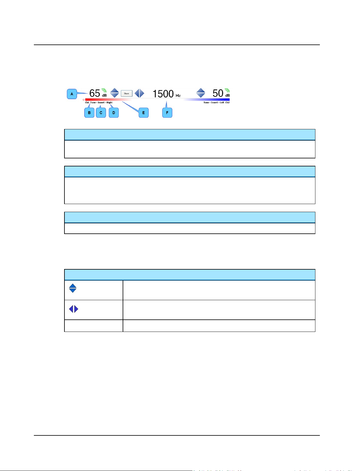
2 Navigating in the OTOsuite Audiometry Module
ABLB Stimulus Bar
A. Intensity
B. Stimulus indicator
C. Transducer indicator
D. Routing indicator
E. Stimulus bar color
F. Frequency
Intensity
Indicated by the dB level above the channel status bars.
• The green triple wave symbol above the level indicates that the stimulus is currently being presented.
Stimulus bar color
Indicates the routing for the channel:
• Blue = left ear
• Red = right ear
Stimulus, transducer and routing indicators
Indicates the stimulus type, the transducer and the routing for each channel.
Test controls
Test controls provide a means of operating the audiometer if you use the mouse and on-screen options to perform tests.
• To enable test controls, select Tools> Options> Audiometry> General> On-screen controls.
Controlling intensity and frequency, and storing data
• Arrow up increases the intensity.
• Arrow down decreases the intensity.
• Arrow left decreases the stimulus frequency.
• Arrow right increases the stimulus frequency.
Store
• Stores the data point.
Otometrics - AURICAL Aud
61
Page 62
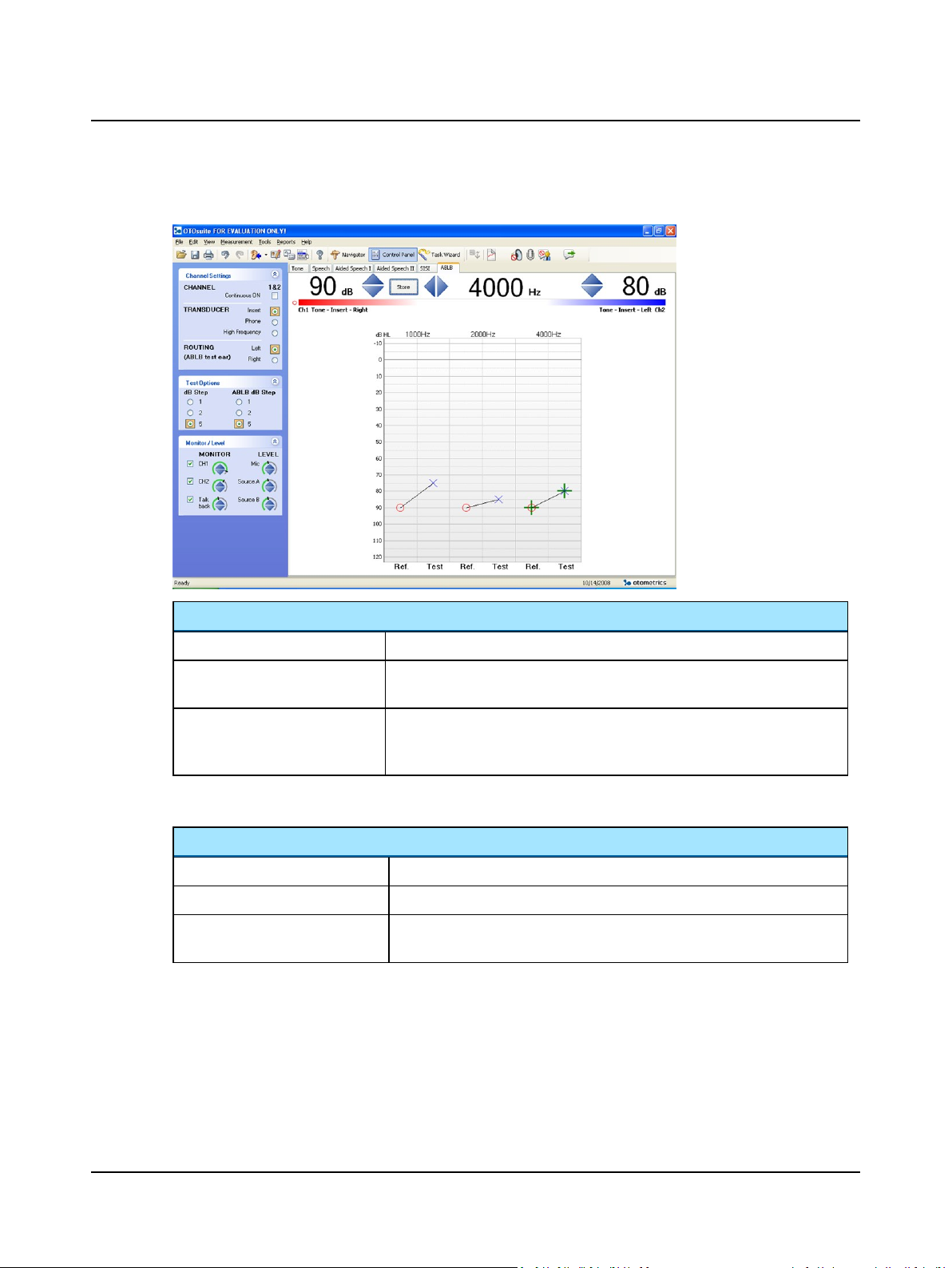
2 Navigating in the OTOsuite Audiometry Module
ABLB data
Data display in ABLB screen
Frequency column
Ref
Test
ABLB editing options
Editing options
Selected point
Delete selected measurement
Delete all at x (e.g. 1000) Hz
• Each frequency displays low to high intensity from top to bottom.
• The ear that is considered to be the reference ear. A steady tone at a particular intensity is presented to this ear.
• The ear that is considered the test ear. A steady tone with adjustable intensity is presented to this ear until equal loudness with the reference ear is
determined.
• e.g. 1000 Hz (90/75) dB
• Deletes the data for the frequency that is currently displayed.
• Deletes the data for that particular column when the frequency is currently
set differently from that column.
62 Otometrics - AURICAL Aud
Page 63
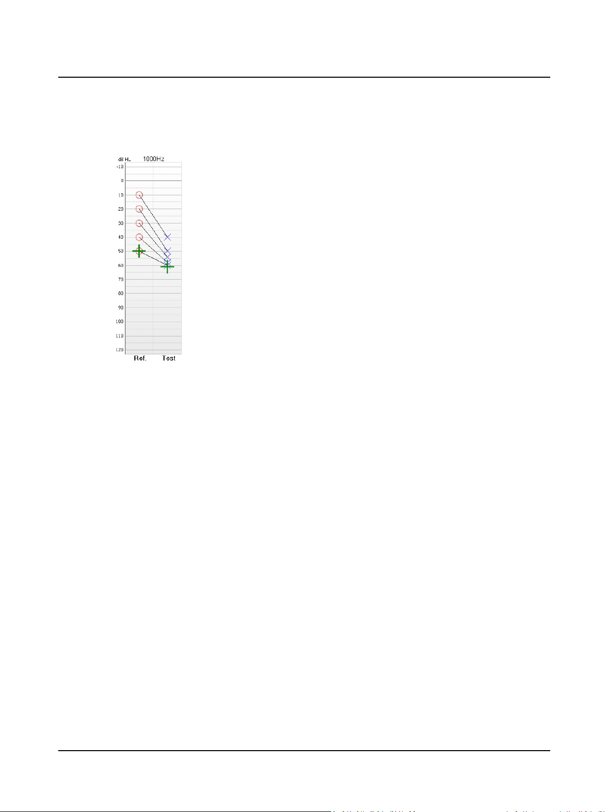
2.14.2.2 The test process
2 Navigating in the OTOsuite Audiometry Module
Tones are presented alternately to both ears, and the patient is asked to make an equal loudness judgment.
2.14.3 TEN (Threshold-Equalizing Noise)
Purpose of the test
The TEN test is a tool for identifying dead regions (regions with no functioning inner hair cells and/or neurones) in the
cochlea. Dead regions can be difficult to determine with standard pure-tone audiometry. Persons with dead regions may
not benefit from hearing instrument amplification in those regions, and amplification may even reduce speech intelligibility. However, people with high-frequency dead regions may have some benefit from amplification for frequencies up
to approximately 70% higher than the "edge frequency" of a dead region.
When the pure-tone signal frequency falls in a dead region, the signal will only be detected when it produces sufficient
basilar membrane vibration at a remote region in the cochlea where there are surviving inner hair cells and neurons. The
amount of vibration produced by the tone at this remote region will be less than in the dead region, and so the noise will
be very effective in masking it. Thus, the signal threshold is expected to be markedly higher than normal.
Procedure
1. Select Tone in the Audiometry Module.
2. Perform a pure-tone test to register a pure-tone audiogram.
3. In Tone, select TEN as masking noise, and route it ipsi-laterally so that both the tone and noise are presented in the
test ear.
The stimulus for each frequency of the pure-tone signal is presented at a level 10 dB above the established threshold.
For frequencies where the hearing loss is less than or equal to 60 dBHL, set the TEN level to 70 dBHL. This is not
unpleasantly loud for most people, and it leads to a definitive result.
When the hearing loss is 70 dBHL or more at a given frequency, set the TEN level 10 dB above the audiometric
threshold at that frequency. For example, if the audiometric threshold is 75 dBHL, set the TEN level to 85 dBHL.
4. If the TEN is found to be unpleasantly loud, or if the maximum TEN level of 90 dBHL is reached, you can set the TEN
level equal to the audiometric threshold. This should still produce a definitive result.
Otometrics - AURICAL Aud
63
Page 64

2 Navigating in the OTOsuite Audiometry Module
It typically takes about 4 minutes per ear to perform the TEN(HL) test for all test frequencies.
Interpretation of the test result
The criteria for diagnosing a dead region at a specific frequency are:
• The threshold of the test tone in the TEN is 10 dB or more above the TEN level.
• The threshold of the test tone in the TEN is 10 dB or more above the audiometric (absolute) threshold.
Sources
Web site: hearing.psychol.cam.ac.uk
2.14.4 Ambient Noise Assessor
Note•The Ambient Noise Assessor feature is based on ANSI standard S3.1, and is available by special request
only. If you are interested in this feature, please contact your local OTOsuite sales representative.
With Ambient Noise Assessor, you can use AURICALFreeFit to measure ambient noise levels during audiometric tests in
the Tone screen and in the Speech screen in tabular view. The permissible noise level is calculated according to ANSI
S3.1.
The Ambient Noise Assessor dialog indicates whether the current noise level is permissible for the current measurement
according to ANSI S3.1. The permissible noise level depends on the frequency and level of the stimulus that is being
tested, as well as other factors, such as the transducer type.
2.14.4.1 Selecting the FreeFit device in OTOsuite
You must select your FreeFit device in the configuration wizard before you can use FreeFit for the first time.
1. In OTOsuite, click Tools> Configuration Wizard..., and then click the Configure... button for PMM.
2. On the Select Your FreeFit page, select your device.
– If the device is not listed, turn on FreeFit by pressing the power button on the device. Check the My device is
turned on and ready to be found check box, and then click Search.
3. Click Finish twice to close the configuration wizard.
For more information about connecting FreeFit, see the "Configuring PMM" section in the AURICALFreeFit and the Probe
Microphone Measurements Module Reference Manual.
2.14.4.2 Measuring Ambient Noise with AURICALFreeFit
To use the Ambient Noise Assessor to monitor noise levels while performing Audiometry, follow this procedure:
1. Fit FreeFit with counterweights. (For detailed
instructions, see the reference manual for
FreeFit.)
64 Otometrics - AURICAL Aud
Page 65
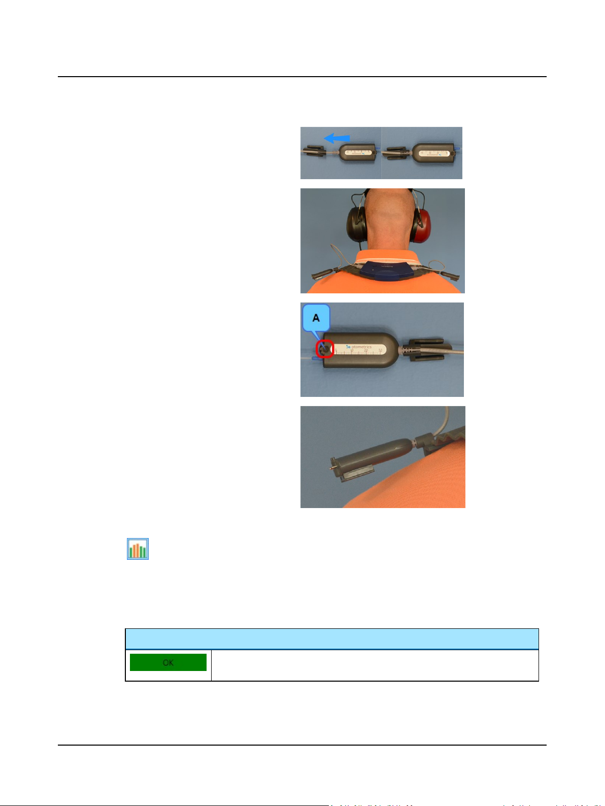
2. Slide the probe cable into place so it fits snugly
in the cable holder on an Ambient Noise
Assessor clip. Repeat with another clip for the
second probe.
3. Place FreeFit on the patient's shoulders. Clip
the probes to the FreeFit collar.
– Position the probes so that they are above
the patient's shoulders.
2 Navigating in the OTOsuite Audiometry Module
4. Adjust each probe carefully:
– The reference microphone should face the
ceiling.
– Ensure that the probe housing does not
touch the patient's clothing and that the
microphone is not covered by anything,
such as clothing or hair.
5. Open the audiometry control panel.
If the Ambient Noise Assessor is not already open, click the button on the Audiometry toolbar.
6. Press the power button on FreeFit. If FreeFit does not connect, ensure that your FreeFit has been selected in the
PMM configuration wizard. Also check the battery status of FreeFit. (See Charging, Powering and Connection Status in
the reference manual for FreeFit.)
The Ambient Noise Assessor dialog indicates the status of the noise level:
A. Reference
microphone
Ambient Noise Status
Otometrics - AURICAL Aud
The measured ambient noise level is below the maximum permissible level for the stimulus that is currently selected.
65
Page 66
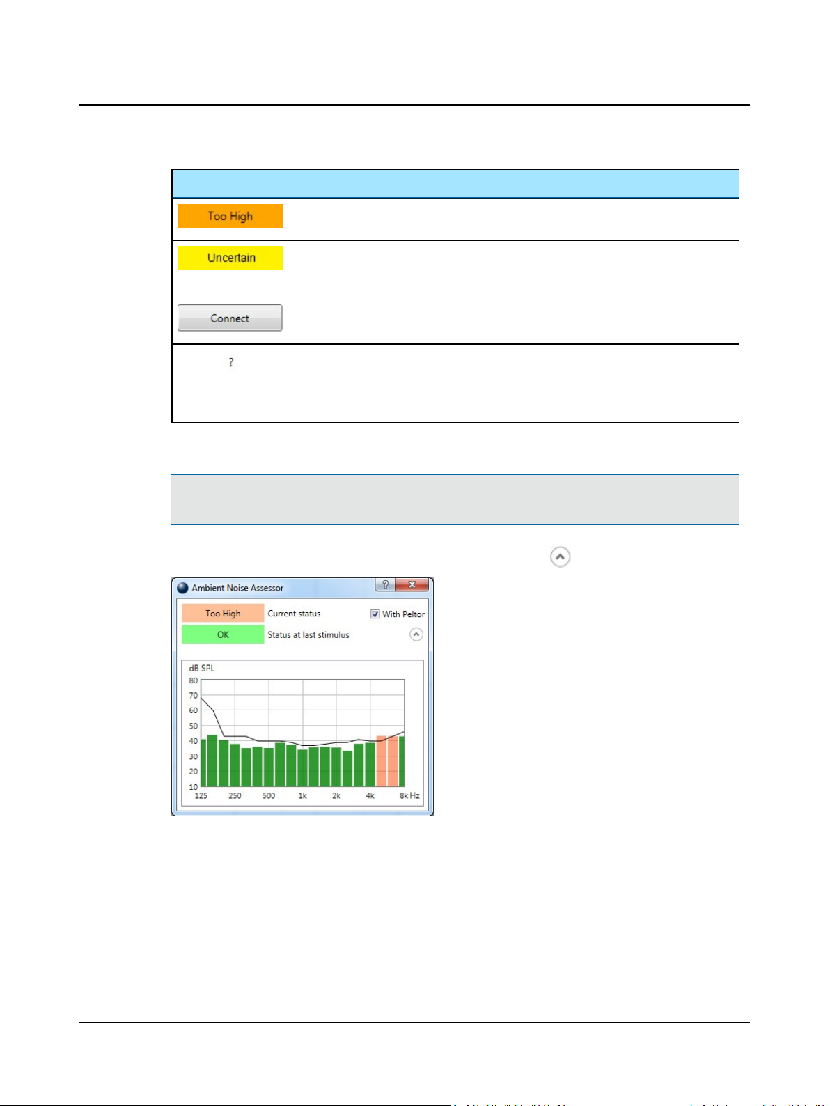
2 Navigating in the OTOsuite Audiometry Module
Ambient Noise Status
The ambient noise level is above the maximum permissible level calculated by the standard. Reduce noise if possible.
The measured ambient noise level is above the maximum permissible noise level.
However, the level is so low that it may be noise from FreeFit itself, rather than ambient
noise.
A
Connect
If you view the
ToneorSpeech
level is calculated, and therefore no status can be displayed. A question mark is also displayed if no audiometer is connected.
7. If you are using TDH39 headphones with Peltor noise reduction enclosure, select the With Peltor option.
button is displayed if FreeFit is not connected.
Ambient Noise Assessor
, you can view the ambient noise bar graph, but no maximum permissible
dialog in an Audiometry test screen other than
Note•The ANSIstandard used to calculate the maximum permissible noise level is based on use of the
TDH39 with Peltor noise reduction.
8. To see a live graphical display of ambient noise, click the Show Details button .
– The curve shows the maximum permissible ambient noise level for the selected stimulus.
– The columns show the current measured noise for each 1/3 octave band between 125 Hz and 8 kHz. Each column
is green, orange, or yellow, corresponding to the color symbols described above.
– If the measured noise exceeds the maximum permissible level 2 seconds before or 0.5 seconds after the stimulus
is presented, a warning marker is displayed at the corresponding frequency. The warning marker will disappear if a
new measurement is made when the ambient noise level is OK. The warning marker also disappears if you switch
to a new test frequency.
9. When the noise level is acceptable to you, you can store a point in the audiogram as you would normally.
66 Otometrics - AURICAL Aud
Page 67
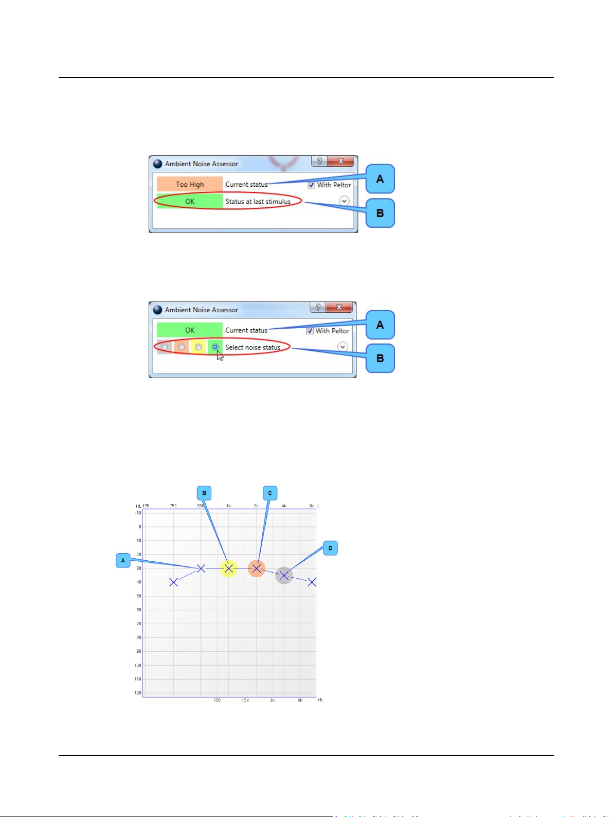
2 Navigating in the OTOsuite Audiometry Module
– In the Tone screen, when a point is stored, the noise level status from the last presentation of the stimulus is
stored.
A. Current noise status
B. Noise status at last stimulus - auto-
matically selected by OTOsuite -
will be stored with audiogram
point
– In the Speech screen, the noise level status is not assigned automatically because OTOsuite cannot judge if noise
registered after the stimulus is ambient noise or the patient's answer. You can use the Ambient Noise Assessor
dialog to keep an eye on the current noise level, and then present the stimulus when the status is OK (Green).
Then you can select the status in the dialog box before storing:
A. Current noise status
B. Noise status at last stimulus - selec-
ted by user - will be stored with
audiogram point
The selected status will be stored when you store a point in the audiogram.
2.14.4.3 Noise level indicators stored with measurements
Tone audiometry
When you make an audiogram using the Ambient Noise Assessor, the background color behind each point in the audiogram indicates the following:
A. No background color: The noise level was below the
maximum permissible level.
B. Yellow: The measured ambient noise level was
above the maximum permissible noise level for the
stimulus. However, the level is so low that it may be
noise from the FreeFit itself, rather than ambient
noise. (See Minimum HTL per transducer type ►
69.)
C. Orange: The measured ambient noise was above the
maximum permissible noise level for the stimulus.
D. Gray: The status of ambient noise is unknown. Either
FreeFit was not activated when the point was measured, or the frequency was stored without the signal
having been presented.
Otometrics - AURICAL Aud
67
Page 68
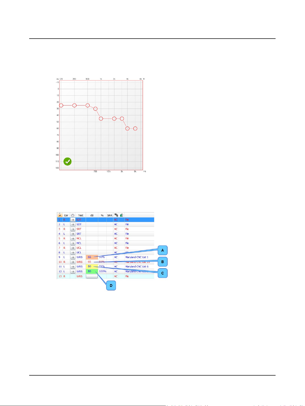
2 Navigating in the OTOsuite Audiometry Module
These indicators are stored with the audiogram. If the noise level was measured and was below maximum permissible
levels for all points in a stored audiogram, a check mark is displayed in the bottom-left corner of the audiogram:
Speech audiometry
When you perform a test in the Speech screen using tabular view, you manually select the status in the Ambient Noise
Assessor dialog, and the selection appears as a background color behind each measurement in the table. The colors have
the following meaning:
A. Orange: The measured ambient noise was above the
B. Gray: the status of ambient noise is unknown. Meas-
C. Yellow: The measured ambient noise level was
D. Green: The noise level was below the maximum per-
2.14.4.4 Activating the Ambient Noise Assessor automatically
You can use the toolbar button to open the Ambient Noise Assessor when you need it, or you can set the feature to open
automatically.
In Options> Audiometry> General> Measurement, Misc. you can set Show Ambient Noise Assessor to Yes. Then the
Ambient Noise Assessor dialog will open automatically when you open the Tone or Speech tab in Audiometry.
maximum permissible noise level for the stimulus.
urements stored with this status appear the same as
measurements made without the Ambient Noise
Assessor activated.
above the maximum permissible noise level for the
stimulus. However, the level is so low that it may be
noise from the FreeFit itself, rather than ambient
noise. (See Minimum HTL per transducer type ►
69.)
missible level.
68 Otometrics - AURICAL Aud
Page 69
2.14.4.5 Minimum HTL per transducer type
The following table describes the minimum HTLs for which the Ambient Noise Assessor can measure ambient noise, for
various transducers. For stimuli below the given level, the Ambient Noise Assessor cannot distinguish between noise produced by the transducer and ambient noise. For stimuli below the minimum level, the ambient noise status indicator will
be yellow.
Transducer Minimum HTL (dB HL)
Bone 30
Supra Aural, TDH 39/MX41 15
TDH39 with Peltor enclosure 0
Insert -10
2.15 Test controls (keyboard, mouse)
2 Navigating in the OTOsuite Audiometry Module
2.15.1 PC keyboard controls
You can open an overview of PCkeyboard shortcuts from the OTOsuite Manuals file.
OTOsuiteManuals was installed on your PCwhen you installed OTOsuite. You can
open OTOsuite Manuals from the Windows Start menu.
Otometrics - AURICAL Aud
69
Page 70

2 Navigating in the OTOsuite Audiometry Module
70 Otometrics - AURICAL Aud
Page 71

3 Preparing for testing
It is important to prepare properly before making measurements with AURICAL Aud and the OTOsuite software. It is timesaving for both you and the client if the environment, the client, the test device, and the software are ready for the test.
3.1 Preparing the test environment
Before you start testing, make sure that the test environment is conducive to testing.
• The test environment should be quiet, preferably in a sound proof booth, for accurate threshold results.
• The test room or sound booth should have a minimum of furniture and hard surfaced articles (i.e. filing cabinets, tables
etc), as these can cause reverberation during sound field testing.Live voice examinations are best carried out when
using a sound booth, so that the client/patient cannot hear the tester's voice directly. With tester and client/patient
in the same room, especially of clients with normal or almost normal hearing, false results could be obtained.
Furniture
The test environment should include
• a comfortable chair for the client,
• a child-sized chair if testing pediatrics,
• a comfortable chair for the assistant.
The examiner should be able to see the client/patient. The client/patient should be seated so that it is not possible to see
what the examiner is doing or how the equipment is being operated. This reduces the likelihood that the client/patient
can anticipate when the stimulus will be presented.
For pediatric testing consider using a highchair, which is a familiar environment for most children and will place them
closer to eye level with the visual reinforcement toys. Make sure if performing visual reinforcement audiometry that the
reinforcing toys can be seen by the child. A child cannot look over and up at a toy until approximately 9 months of age.
Lighting
The lighting in the booth should be bright enough for the examiner to adequately see the client.
Toys
If testing pediatrics, several interesting toys are needed to center the child (obtain the child's attention toward the assistant or tester) prior to stimulus presentation. It is best if these toys do not produce sounds.
The child should be conditioned to respond to the sound of the stimulus only. Competing sounds from toys can confuse
the child and reduce the reliability of the test.
Soft toys are needed to keep a young child's attention during behavioral observation or visual reinforcement audiometry.
Younger children like to tap the toy on the highchair tray and therefore a toy that does not create much sound would be
more appropriate during testing.
Blocks, buckets, puzzles are needed to keep a child's attention during play audiometry.
3.2 Preparing the test equipment
Accessories
Make sure that you have connected the required accessories to the audiometer:
• headphones
• insert phone(s)
• bone oscillator
• patient responder.
Otometrics - AURICAL Aud
71
Page 72

3 Preparing for testing
AURICAL Aud and the Audiometry module
• Make sure the cables of the test equipment are connected correctly.
• Launch OTOsuite and the Audiometry module on the PC (see the OTOsuiteUser Guide).
• Make sure AURICAL Aud is switched on.
• Make sure the connection between the Audiometry module and AURICAL Aud is enabled.
See Configuring the Audiometry Module ► 101.
3.3 Listening check
Perform listening checks routinely to make sure that the equipment is functioning properly.
• Use a person who has auditory thresholds below 10 dB and make sure that he or she can hear a very faint sound for
each stimulus type, frequency and for each transducer at 0 to 5 dB.
• If the person cannot hear the stimulus, contact the manufacturer or local representative to troubleshoot the system.
• It is recommended that the system be calibrated annually or according to the local requirements.
3.4 Preparing the client
3.4.1 Hygienic precautions
It is important that hygienic precautions are taken to protect the client from cross-infection. Be sure to follow any established infection control procedures for the setting in which you are working.
• Headphones
Clean the headphones between patients, e.g. with a non-alcohol based antibacterial wipe, such as Audiowipes.
• Insert earphones
Warning • To prevent cross-infection, use new eartips when you test the next client.
3.4.2 Inspecting the client’s ear(s)
1. Position the client so that you can easily access the client’s ear(s).
2. Grasp the pinna and gently pull it back and slightly up and away from the client's head.
3. Inspect the ear canal and make sure that you can see the ear drum.
If you can see apparent narrowing of the ear canal, it may be blocked by vernix or debris, or it may not be straight.
4. If the ear canal is blocked, for instance by vernix or debris, the outcome of the procedures may be affected.
Clean the ear canal if required.
3.5 Proper transducer placement
Headphones
1. Loosen the headband and place both the left and right side of the headphones simultaneously.
72 Otometrics - AURICAL Aud
Page 73

3 Preparing for testing
2. Make sure that the blue indicator is on the left ear and the red indicator is on the right ear. The center of the headphone diaphragm should be directly opposite the opening of the ear canal for the left and right side.
Note•If the headphones are not placed properly, there is risk of causing the ear canal to collapse which will res-
ult in elevated thresholds.
3. Ask the patient if the headphones are comfortable.
4. Tighten the headband while holding the headphones in place with your thumbs.
5. Examine the placement of the headphones to make sure they are level, and properly positioned.
Insert Earphones
Young children tolerate insert earphones better than headphones.
The insert earphones are color-coded:
• the blue indicator for the left ear,
• the red indicator for the right ear.
1. Select the largest foam eartip that will fit into the patient's ear.
If the eartip is too small the sound will leak out and the dB level will not be accurate at the eardrum.
Insert earphones have greater attenuation between ears especially at the low frequencies; this reduces the need for
masking.
2. It is best to clip the insert earphone transducers behind the child or on the back of their clothing and then fit the
foam eartip into the child's ears.
If the foam eartip is a little too large, consider cutting it down to make it a little smaller.
Bone Oscillator
Note•For unmasked bone thresholds, you can store binaural data:
Note•If there is a difference of 10dB or greater between the bone conduction threshold and the air conduction
threshold of the same ear, masking is needed. The Masking Assistant can assist you in determining which
thresholds need to be masked.
Note•If the SRT of the test ear and the SRT or PTA of the nontest ear differ by 45dB or more, masking is
needed.
If the SRT of the test ear and the bone conduction PTA of the nontest ear differ by 45 dB or more, masking is
needed.
Mastoid placement
1. Move any hair covering the mastoid out of the way and place the flat round part of the bone oscillator securely on the
boniest portion of the mastoid without any part of the transducer touching the external ear.
2. Make sure the bone oscillator is tight on the mastoid but still comfortable.
Otometrics - AURICAL Aud
73
Page 74

3 Preparing for testing
3. If you are going to perform masking with earphones, position the other end of the bone oscillator headband over the
patient's temple on the opposite side of the head so that the headband of the earphones and bone oscillator fit on
the patient's head.
74 Otometrics - AURICAL Aud
Page 75

4 Examples of audiometric testing
4.1 Testing the older child or adult patient
4.1.1 Assessing pure tone threshold using the Hughson/Westlake procedure
Threshold
This is the lowest level at which the patient responds to the stimulus at least 50% of the time.
1. Talk to the patient while you walk him/her to the booth. This will give you some idea of how well he/she is hearing.
– Ask him/her which ear is his/her better hearing ear.
2. Perform otoscopic inspection of the ear canals to make sure that the ears are free from occluding cerumen (earwax) or
debris.
3. Optional: Perform tympanometry and reflexes prior to audiometric test.
4. Properly place the earphones. Begin the test with the air conduction transducer.
– If you are planning to test high frequencies, use the HDA 300 earphones for all frequencies (if they have been cal-
ibrated for all frequencies).
5. Give the patient the responder(s).
6. Instruct the patient so that he/she knows what to expect: "You will hear various sounds from low pitches to high
pitches. Push the button when you hear a sound, even if it is very soft."
7. If the patient reports having tinnitus, consider using a pulsed tone for testing.
8. Make sure that the control panel of the OTOsuite software is set to the correct transducer and desired routing, sound
level, and frequency. Make sure that threshold test (THR) is selected.
9. Begin the test in the ear reported as the better hearing ear.
– Tell the patient in which ear the test will begin.
10. Start the testing at 1000 Hz.
11. Start presenting the tone at a sound level that should be clearly audible to the patient to confirm that instructions for
responding were understood.
– Present the tone for 1 to 2 seconds.
12. If the patient responds to the initial sound level presented, proceed with the test by decreasing the level in 10dB
steps until no response is obtained.
– Increase the level in 5dB steps until a response is obtained again.
– Continue decreasing in 10dB steps and increasing in 5dB steps until you determine the lowest level at which the
patient responds correctly to two of three trials. This is the threshold.
– Once threshold is obtained, store the response.
13. Continue testing with this up/down procedure in the following frequency order: 2000, 4000, 8000, 500, 250, 125,
and reconfirm the threshold at 1000Hz.
– If there is a 20dB difference or greater between octaves, test the interoctave frequencies.
– Talk to the patient occasionally. Encourage the patient to concentrate on the task. This will keep your patient
from getting bored or becoming an unreliable responder.
14. Switch to the other ear and tell the patient to listen for the sounds in that ear.
15. Repeat steps 11 to 13.
Otometrics - AURICAL Aud
75
Page 76

4 Examples of audiometric testing
16. If there is a difference of 40dB or more between the test ear threshold and nontest ear threshold, the better ear
must be masked to test the poorer ear. The Masking Assistant can assist you in determining which thresholds need to
be masked.
17. To use masking noise in combination with the pure tone, either check Stim. Lock to coordinate the presentation of
two channels or check Continuous On to keep the masking channel presenting continuously.
18. After the air conduction thresholds are determined, bone conduction audiometry can be performed.
19. Properly place the bone oscillator.
20. Instruct the patient again to push the button in response to the tone even if the stimulus is very soft.
21. Make sure that the control panel of the OTOsuite software is set to the correct transducer and desired routing, sound
level, and frequency.
22. Repeat steps 9 to 13.
– If there is a difference of 10dB or greater between the bone conduction threshold and the air conduction
threshold of the same ear, masking is needed. The Masking Assistant can assist you in determining which
thresholds need to be masked.
23. When all air and bone conduction thresholds are determined, the pure tone average (PTA) for each will appear in the
PTA/AI box. The Articulation Index (AI) and the overlay options can be used for counseling the patient.
24. Click in the Reliability box to report the reliability of the patient's responses during testing - Good, Fair, or Poor.
4.1.2 Assessing pure tone or speech most comfortable loudness level (MCL)
1. Properly place the earphones.
– Begin the test with the air conduction transducer.
2. Instruct the patient that you are trying to find the level at which he/she is most comfortable listening to the sounds.
3. Make sure that the control panel of the OTOsuite software is set to the correct transducer, desired routing and sound
level.
– Make sure that most comfortable level test (MCL) is selected.
4. Start at a moderate level. Present the stimulus and ask the patient if the current level is comfortable or if he/she
would prefer it louder or softer.
– Increase and decrease the sound level until the patient's preferred level is determined. This is the MCL.
– Once MCL is obtained, store the response.
5. Repeat steps 3 and 4 for each frequency if performing MCL testing for pure tones.
6. Switch to the other ear and tell the patient to listen for the sounds in that ear.
7. Repeat steps 3 and 4 for the opposite ear.
4.1.3 Assessing pure tone or speech uncomfortable loudness level (UCL)
1. Properly place the earphones.
– Begin the test with the air conduction transducer.
2. Instruct the patient that you are trying to find the level at which the sound is uncomfortably loud. It should be tolerable and not painful.
3. Make sure that the control panel of the OTOsuite software is set to the correct transducer and desired routing and
sound level.
– Make sure that uncomfortable loudness testing (UCL) is selected.
76 Otometrics - AURICAL Aud
Page 77

4 Examples of audiometric testing
4. Start at a moderate level. Present the stimulus and then ask the patient if the current level is okay or uncomfortable.
Increase the presentation level in 5 to 10dB steps until the patient's uncomfortable loudness level is determined.
5. Repeat steps 3 and 4 for each frequency if performing UCL testing for pure tones.
6. Switch to the other ear and tell the patient to listen for the sounds in that ear.
7. Repeat steps 3 and 4 for the opposite ear.
4.1.4 Assessing speech reception threshold (SRT) using the Hughson/Westlake procedure
1. Properly place the earphones.
– Begin the test with the air conduction transducer.
2. Instruct the patient so that he/she will know what to expect: "You will hear various words, like hotdog, ice cream, ect.
When you hear a word, repeat it back to me even if the word is very soft. It is okay to guess if you are unsure of the
word."
3. Make sure that the control panel of the OTOsuite software is set to the correct transducer and desired routing and
sound level.
– Make sure that speech reception threshold (SRT) is selected.
4. Begin the test in the ear that has the lower PTA.
– Inform the patient in which ear the test will begin.
5. Start presenting words at a level that should be clearly audible to the patient to confirm that the instructions for
responding were understood.
6. It is best to use recorded speech to reduce variability.
– If the automated presentation speed of the recorded speech is too fast for the patient, you can deliver the recor-
ded words one at a time by double-clicking on the word in the word list.
– You can also present the speech material using monitored live-voice.
7. If the patient responds to the initial sound level presented, proceed with the test by decreasing the level in 10dB
steps until no response is obtained.
– Increase the level in 5dB steps until a response is obtained again.
– Continue decreasing in 10-dB steps and increasing in 5-dB steps until you determine the lowest level at which the
patient responds correctly to two of three trials. This is the SRT.
– Once the SRT is obtained, store the response.
8. If the SRT of the test ear and the SRT or PTA of the nontest ear differ by 45dB or more, masking is needed.
If the SRT of the test ear and the bone conduction PTA of the nontest ear differ by 45 dB or more, masking is needed.
9. Switch to the other ear and tell the patient to listen for the words in that ear.
10. Repeat steps 3 to 7.
11. The SRT will be ±8dB of the PTA for each ear if the data are reliable.
4.1.5 Assessing word recognition score
1. Properly place the earphones.
– Begin the test with the air conduction transducer.
2. Instruct the patient so that he/she will know what to expect: "You will hear various words, like bird, dog, etc. When
you hear a word, repeat it back to me. This time the words will all be loud enough to hear. It is okay to guess if you
are unsure of the word."
Otometrics - AURICAL Aud
77
Page 78

4 Examples of audiometric testing
3. Make sure that the control panel of the OTOsuite software is set to the correct transducer and desired routing and
sound level.
– Make sure that word recognition score (WRS/SRS) is selected.
4. Begin the test in the ear with the lower PTA and/or SRT.
– Tell the patient in which ear the test will begin.
5. It is best to use recorded speech to reduce variability.
– If the automated presentation speed of the recorded speech is too fast for the patient, you can deliver the recor-
ded words one at a time by double-clicking on the word in the word list.
– You can also present the speech material using monitored live-voice.
6. Present the words at a sound level that is 30 to 40dB higher than the SRT score.
– Some examiners prefer to give the patient a couple of words to make sure that the response instructions are
understood. These words should not be part of the test word list as familiarity can bias the test.
7. Score the responses using the +/- buttons. Typically, 25 or 50 words are presented in a list. Once all the words on the
list have been presented, you have a percentage correct. This is the WRS.
– Once the WRS is obtained, store the response.
8. Switch to the other ear and tell the patient to listen for the words in that ear.
9. Repeat steps 6 to 7.
10. Type any desired notes regarding the test (for example, "NU-6, word list 3A") in the box to the left of the scores (tabular view) or symbols (graphical view).
4.2 Special Tests
4.2.1 Performing Tone Decay using the Modified Carhart Method
1. Properly place the earphones.
– Begin the test with the air conduction transducer.
2. Give the patient a responder.
3. Instruct the patient so that he/she knows what to expect: "You will hear a continuous tone. Press the button on the
responder as long as the tone stays the same. If the pitch changes or you can no longer hear the tone, release the
responder button."
4. Select tone decay in the Test Selector.
– Make sure that the control panel of the OTOsuite software is set to the correct transducer, and desired routing,
sound level and frequency. Any frequency can be used.
5. Make sure that the tone decay box and the timer box have appeared in the display.
6. Start the test at 5dB above the patient's threshold for that frequency in that ear.
7. As soon as the subject responds, start the timer. You will be presenting a tone for at least one minute.
8. If the patient indicates that the tone was audible at the same pitch for one minute, then the test is complete.
– Store the test result in the Tone Decay Box.
9. If the patient indicates that the tone is no longer audible or changes pitch before one minute passes, increase the
level of the tone by 5dB.
– Reset the timer when you increase the level and begin timing again.
78 Otometrics - AURICAL Aud
Page 79

10. Continue increasing the tone by 5dB until a level is reached at which the patient indicates that the tone is audible at
the same pitch for one minute.
11. If desired, test additional frequencies or the opposite ear.
12. Store the test result in the Tone Decay box.
4.2.2 Performing a pure tone Stenger
1. To perform this test, the pure tone thresholds for the chosen stimulus frequency should be at least 20 dB different in
each ear.
– You must suspect that the patient is malingering.
2. Properly place the earphones.
– Begin the test with the air conduction transducer.
3. Instruct the patient to push the button in response to the tone even if the sound is very soft.
4. Select Puretone Stenger in the Test Selector.
– Make sure that the control panel of the OTOsuite software is set to the correct transducer and desired routing,
frequency, and sound level.
– Choose any frequency.
– Set the level for the better ear at 10dB above recorded threshold and set the level in the poorer ear at 10dB
below recorded threshold.
5. Make sure that the Stenger box has appeared in the display.
6. Make sure that Stim. Lock is enabled and present the tone to both ears simultaneously.
7. If the patient truly has a hearing loss in the poorer ear, he/she will only hear the presented tone in the better ear and
will respond that the tone is present.
– This is a negative Stenger response.
8. If the patient does not truly have a hearing loss in the poorer ear, he/she will only hear the presented tone in the
reportedly poorer ear. As the patient is trying to appear as if he/she has a hearing loss in that ear, the patient will not
respond to the tone.
– This is a positive Stenger response.
9. Store the test result in the Stenger box.
4 Examples of audiometric testing
4.2.3 Performing speech Stenger
1. To perform this test, the SRT should be at least 20dB different in each ear.
– You must suspect that the patient is malingering.
2. Properly place the earphones. Begin the test with the air conduction transducer.
3. Instruct the patient to repeat the word back to the examiner even if the word is very soft.
4. Select Speech Stenger in the Test Selector.
– Make sure that the control panel of the OTOsuite software is set to the correct transducer, and desired routing
and sound level.
– Set the level for the better ear at 10dB above recorded SRT and set the level in the poorer ear at 10dB below
recorded SRT.
5. Make sure that the Stenger box has appeared in the display.
6. Make sure that Stim. Lock is enabled and present the word to both ears simultaneously.
Otometrics - AURICAL Aud
79
Page 80

4 Examples of audiometric testing
7. If the patient truly has a hearing loss in the poorer ear, he/she will only hear the presented word in the better ear and
will respond by repeating the word.
– This is a negative Stenger response.
8. If the patient does not truly have a hearing loss in the poorer ear, he/she will only hear the presented word in the
reportedly poorer ear. As the patient is trying to appear as if he/she has a hearing loss in that ear, the patient will not
repeat the word.
– This is a positive Stenger response.
9. Store the test result in the Stenger box.
4.2.4 Performing Weber
1. Properly place the bone oscillator on the forehead.
2. Instruct the patient so that he/she knows what to expect: "You will hear a tone. Tell me whether you hear the tone in
the left, right or both ears."
3. Select Weber in the Test Selector.
– Make sure that the control panel of the OTOsuite software is set to the correct transducer and desired routing,
sound level and frequency.
4. Make sure that the Weber box has appeared in the display.
5. Present a pure tone at a frequency below 1000Hz and a sound level above the patient's bone conduction threshold.
6. If the patient reports hearing the tone equally in both ears, this is indicative of normal hearing.
7. If the patient reports hearing the tone in the poorer ear, this is indicative of a conductive hearing loss.
8. If the patient reports hearing the tone in the better ear, this is indicative of a sensorineural hearing loss.
9. Store the test result in the Weber box.
4.2.5 Performing Rinne
1. This test is performed using a 256 or 512Hz tuning fork and compares that patient's hearing to air and bone conduction.
– This test is used to confirm a conductive hearing loss.
2. Instruct the patient that two tones will be presented to him/her. Ask the patient to tell you when the tone can no
longer be heard.
3. Make sure that the Rinne box is present.
4. Strike the tuning fork against the knee or the elbow, not the table, otherwise the vibrations will be excessive and
cause the patient discomfort.
5. Hold the fork for 2-3 seconds and then place it on the patient's mastoid.
Note•The time interval from initial stimulus perception to inability to hear the tone.
6. Strike the fork again.
7. Hold the fork for 2-3 seconds and then place it in front of the patient's ear.
Note•The time interval from initial stimulus perception to inability to hear the tone.
80 Otometrics - AURICAL Aud
Page 81

8. If air conduction perception is better than bone conduction, this is a positive Rinne and agrees with normal hearing
9. If bone conduction perception is better than air conduction, this is a negative Rinne and indicative of a conductive
hearing loss.
10. If air conduction and bone conduction are equal, this is a positive Rinne and indicative of a sensorineural hearing loss.
11. Store the test result in the Rinne Box.
4.2.6 Performing Alternate Binaural Loudness Balancing (ABLB) test
If you have measured thresholds prior to performing ABLB, then these will appear already plotted in the ABLB graph.
1. Properly place the earphones.
2. Give the patient the responder(s).
3. Instruct the patient so that he/she knows what to expect: "You will hear a continuous tone. The level of this tone will
be changed periodically. Press the button on the responder immediately each time you hear a change. I will ask you if
the test tone is softer than, louder than or equal to the reference tone in the opposite ear."
4. Choose the ABLB tab or select ABLB in the Test Selector.
– Make sure that the control panel of the OTOsuite software is set to the correct transducer and desired routing.
– If left ear is selected as the test ear in the Control Panel Routing section, then the right ear will be the reference
ear.
5. Set the reference level (Ch1).
6. Set the test level (Ch2) to 10dB above the patient's threshold for that ear.
7. Adjust the level of the test signal (Ch2) until the patient reports that the two signals sound equally loud.
8. Store the data points.
9. Repeat steps 5 to 8 for additional frequencies.
10. If desired, switch routing to test the opposite ear and repeat steps 5 to 8.
4 Examples of audiometric testing
4.2.7 Performing Short Increment Sensitivity Index (SISI) test
1. Properly place the earphones.
2. Give the patient the responder(s).
3. Instruct the patient so that he/she knows what to expect: "You will hear a continuous tone. The level of this tone will
be changed periodically. Press the button on the responder immediately each time you hear a change."
4. Choose the SISI tab or select SISI in the Test Selector.
– Make sure that the control panel of the OTOsuite software is set to the correct transducer and desired routing.
– Make sure that the frequency is correct.
5. Begin the test in the ear with the lower PTA or SRT.
6. Start with 5dB SISI dB step and set the level 20dB above the patient's threshold for that frequency in that ear.
7. The test begins with 1000 Hz.
8. Make sure that the patient understands the response task.
9. Change the SISI dB step to 1dB. Set the level 20dB above the patient's threshold for that frequency in that ear and
press the Play button.
10. Store the data points.
11. Repeat steps 6 to 10 for additional frequencies.
Otometrics - AURICAL Aud
81
Page 82

4 Examples of audiometric testing
4.3 Testing with sound files
4.3.1 Playing sound files without word lists
Prepare playback
1. Use either Int. CD or Int. File as Sound Source.
2. If Int. CD is chosen, select CD Drive Selection and/or CD Track Selection in the Options dialog or directly in the
Player Panel. This will list CD tracks in the Player Panel combo box.
3. If Int. File is chosen, select Sound File Selection in the Options dialog or browse for a folder containing sound files in
the Player Panel. This will list all sound files contained in the same folder as the Sound File Selection file in the
Player Panel combo box.
How to play back / stop playback
1. Use either the Play or Pause button.
2. A click on the Pause button (actually a stop icon) will pause playing (this is different when using word lists).
3. A click on Reset stops the playback and resets the score.
How to score
• Use the score buttons or shortcut keys (+, -).
When to reset score
Notice the field Reset Score Counter in the Options dialog.
• Reset Score Counter = True
The Scoring panel is reset if you change Channel Settings (except Continuous On), the Intensity or if the Reset but-
ton is clicked.
• Reset Score Counter = False
Does not change the score even if Reset is clicked.
4.3.2 Playing sound files with word lists
Prepare playing
1. Use either Int. CD or Int. File as Sound Source.
2. If Int. CD is chosen, select a CD drive in CD Drive Selection in the Options dialog or in the Player Panel. It is import-
ant that an XML file (extension *.wordlistdefinition) describing the word lists exist on your PC (in the installation
folder). If not the tracks on the CD will be listed and not the actual words.
3. If Int. File is chosen, select a .wav file in the Sound File Selection which is located in the same folder as a word-
listdefinition file. You can also browse for a folder in the Player Panel that contains a wordlistdefinition.
How to play/stop files
1. Use either the Play or Pause button.
2. A double click on a word in the Word list control plays the selected word.
3. A Play button click will start to play back the word list from the current index to the end.
4. If you like to change index during playback, just change index in the Word list control and it will keep on playing from
that position.
82 Otometrics - AURICAL Aud
Page 83

How to score
• Use the score buttons or shortcut keys (+, -), or make a right click on a given word already played in the Word list con-
trol.
When to reset score
Notice the field Reset Score Counter in the Options dialog.
• Reset Score Counter = True
The Scoring panel as well as the Word list control images (+, -) is reset if changes are made to the Channel Settings
(except Continuous On), the Intensity or when the Reset button is clicked.
• Reset Score Counter = False
We actually reset the score in some cases even if Reset Score Counter = False. This is in situations where we go from
using a word list to e.g. StimulusCH1=StimulusCH2=Mic.
4.4 Performing sound-field speech audiometry off site
When a service technician performs an annual calibration on your AURICAL Aud speaker, the calibration is performed in
the location where you most often use AURICAL Aud, for example, in your consultation office. However, you may want to
take AURICAL Aud with you to perform sound-field speech audiometry in other locations, such as in a client's home or in a
nursing home. In that case, the AURICAL Aud speaker must be calibrated for the new location. You can use a sound level
meter, together with OTOsuite, to make a temporary manual calibration.
4 Examples of audiometric testing
Overview of portable sound-field audiometry tasks
To prepare for off-site sound-field speech audiometry:
• Enable portable sound-field audiometry in the Configuration Wizard.
• When you are at the site where you will perform off-site sound-field audiometry, click Calibrate in the Speech Audi-
ometry control panel to open the Portable Sound-Field Audiometry window. Use this window to:
– Calibrate one speaker - first the primary signal, then the secondary signal
– Calibrate the second speaker, if applicable. First the primary signal, then the secondary signal
– Save the calibration values.
• To use the new calibration values, select Portable Sound-Field Audiometry in the Control panel, and then perform
speech audiometry as you normally would.
If you move to another off-site location, remember to repeat the manual calibration.
When you return to your default location, deselect Portable Sound-Field Audiometry in the control panel.
4.4.1 Enabling portable sound-field audiometry
Before you can make a manual calibration of the speaker, you must:
• Select Enable Portable Sound-Field Audiometry in the configuration wizard, on the Preferences page.
Once you have enabled portable audiometry, the Portable Sound-Field Audiometry option appears in the control panel
on the Speech tab.
4.4.2 Performing a manual calibration of AURICAL Aud speakers
To prepare for portable sound-field audiometry, you must configure the speakers and then calibrate them.
Otometrics - AURICAL Aud
83
Page 84

4 Examples of audiometric testing
1. In the Speech Audiometry control panel, click the Calibrate button to open the Portable Sound-Field Audiometry
window.
First, configure the speaker setup:
2. Select the output that you want to calibrate- either the built-in AURICAL Aud speaker, or external speakers.
3. Indicate the speaker's position in relation to the client.
4. If you are using two speakers, you can select the Lock Stimulus to Speaker 1 option to present the stimulus from
speaker 1 and masking from speaker 2.
Calibrate the speaker or speakers:
5. Before you start the calibration, position the sound level meter in the location where the client's head will be.
6. Select the speaker that you want to calibrate.
If you use two speakers, you must calibrate first one and then the other. If you use only one speaker, you only need to
calibrate the left speaker.
7. Click Start calibration.
The primary signal is played.
8. Use the Up and Down buttons to adjust the level until the sound level meter reads 70 dB and then click
Accept Level
The primary signal stops and the secondary signal is played.
9. Again, use the arrow buttons to adjust the level until the sound level meter reads 70 dB, and then click Accept Level.
10. If you are using two speakers, select the second speaker as the channel to calibrate, and then repeat steps 6-8.
11. Click OK to save the calibration values and close the dialog.
4.4.3 Using manual speaker calibration values
After you perform a manual calibration of the AURICAL Aud speakers, you can use the values for the room where the calibration was performed.
To use the manual calibration values:
1. In the Control panel, select Portable Sound-Field Audiometry.
Now you can continue to perform Speech audiometry as you normally would.
84 Otometrics - AURICAL Aud
Page 85

5 Unpacking and Installing
This section applies to AURICAL Aud as well as to the various accessories available. If the accessories are not part of your
configuration, disregard the instructions relating to the accessories.
To install and get started with AURICAL Aud and the OTOsuite Audiometry Module, follow the sequence below:
• Install OTOsuite on the PC before you connect to AURICAL Aud from the PC.
• Unpack AURICAL Aud (see Unpacking ► 86).
• Assemble AURICAL Aud (see Assembling AURICAL Aud ► 93).
• Connect the cables of the test equipment. See
– Desktop or wall installation ► 94
– AURICAL speaker unit installation ► 95
• Run the OTOsuite Configuration Wizard to connect to and set up communication with AURICAL Aud. (See Configuring
the Audiometry Module ► 101.)
5.1 Requirements to the location
A sound cabin or sound treated room is not necessary, but it is recommended that you use a room where reverberation
time is not too long.
To ensure safe performance, AURICAL Aud must be correctly installed and the requirements listed in Standards and
Safety ► 115 and Technical specifications ► 119 must be complied with.
Warning • The charger unit should be kept away from the client area.
Warning • Keep AURICAL Aud away from all liquids and sources of heat (for detailed specifications, see Oper-
ating environment ► 126).
Warning • It is recommended to install the unit in an environment that minimizes the amount of static electricity.
For example, anti-static carpeting is recommended.
5.1.1 Requirements to noise in the test environment
Audiometry testing does not require a quieter testing environment than do other traditional Real Ear Measurement systems.
Although Audiometry testing is designed for use in a regular dispensing office environment, the test environment should
in some cases be adapted to suit the specific test types.
• Make sure that the test environment is as quiet as possible. The quieter the room is, the more accurate your testing
will be.
It is very important that the measurements are not influenced by sounds or noise relating to anything else than the
presented test signals. Measurements of peak levels will be influenced by any sounds louder than the presented test
signals. Even extremely brief sounds may impact the measurements.
It is therefore important that the environment is well controlled to prevent any unforeseen influence.
• Check that testing is not being done under an air conditioner or in front of a fan or ventilator.
Otometrics - AURICAL Aud
85
Page 86
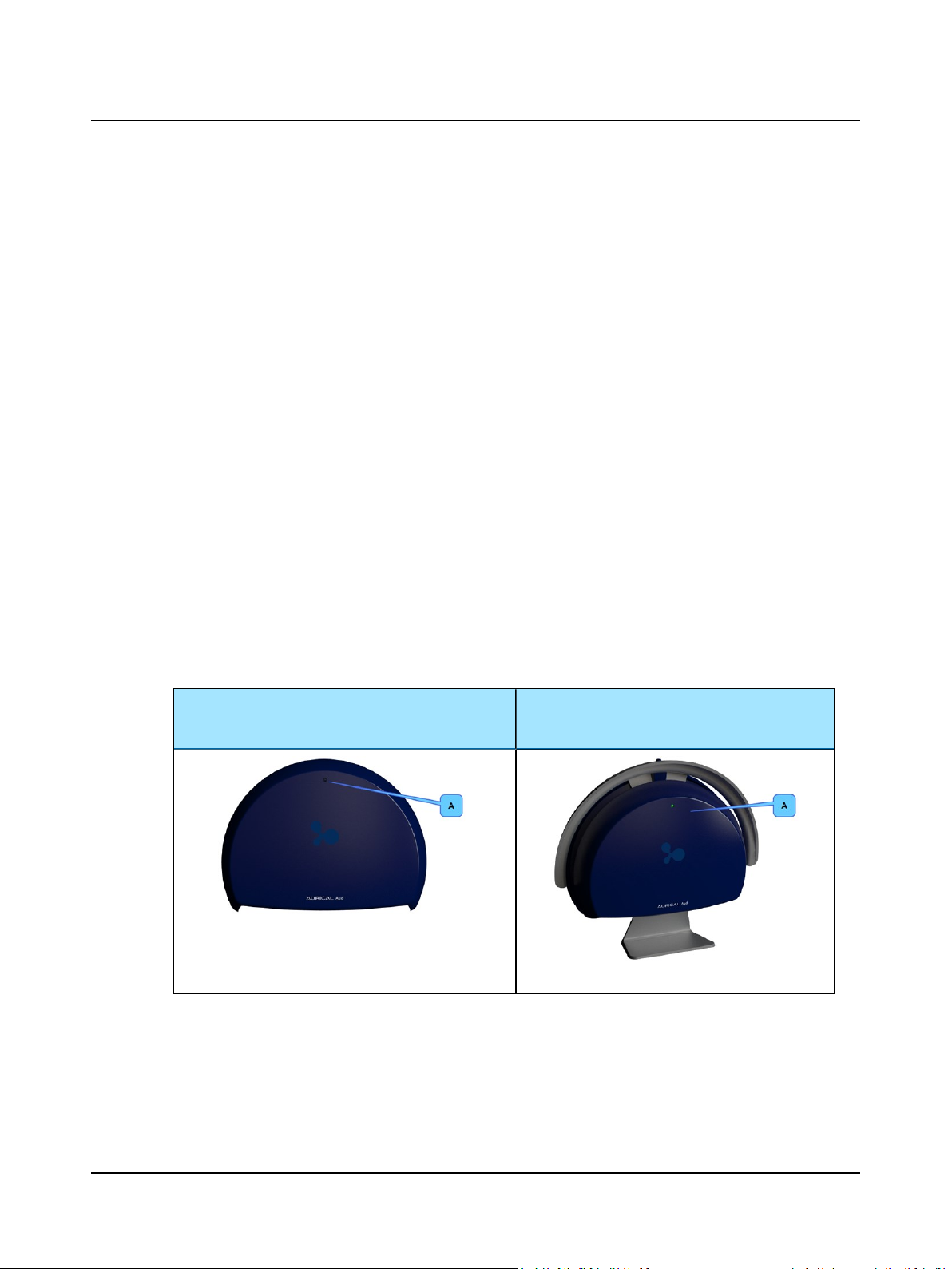
5 Unpacking and Installing
5.2 Unpacking
1. Unpack the device carefully.
When you unpack the device and accessories, it is a good idea to keep the packing material in which they were
delivered. If you need to send the device in for service, the original packing material will protect against damage during transport, etc.
2. Visually inspect the equipment for possible damage.
If damage has occurred, do not put the device into operation. Contact your local distributor for assistance.
3. Check with the packing list to make sure that you have received all necessary parts and accessories. If your package is
incomplete, contact your local distributor.
4. Check the Test Report (Calibration Certificate), make sure that the transducers (headphones and bone oscillator) are
the correct ones, and that they comply with the ordered calibration standards.
5.3 Storing
If you need to store AURICAL Aud before you put it into operation, follow the guidelines below:
• Store AURICAL Aud and accessories in the boxes provided to protect the equipment from damage.
• Store AURICAL Aud and accessories in a dry environment.
See also Transport and storage ► 126.
5.4 Views of AURICAL Aud
5.4.1 AURICAL Aud
Front view - desktop version Front view - mounted on AURICAL speaker
A. On/Off indicator
unit
'
A. On/Off indicator
86 Otometrics - AURICAL Aud
Page 87
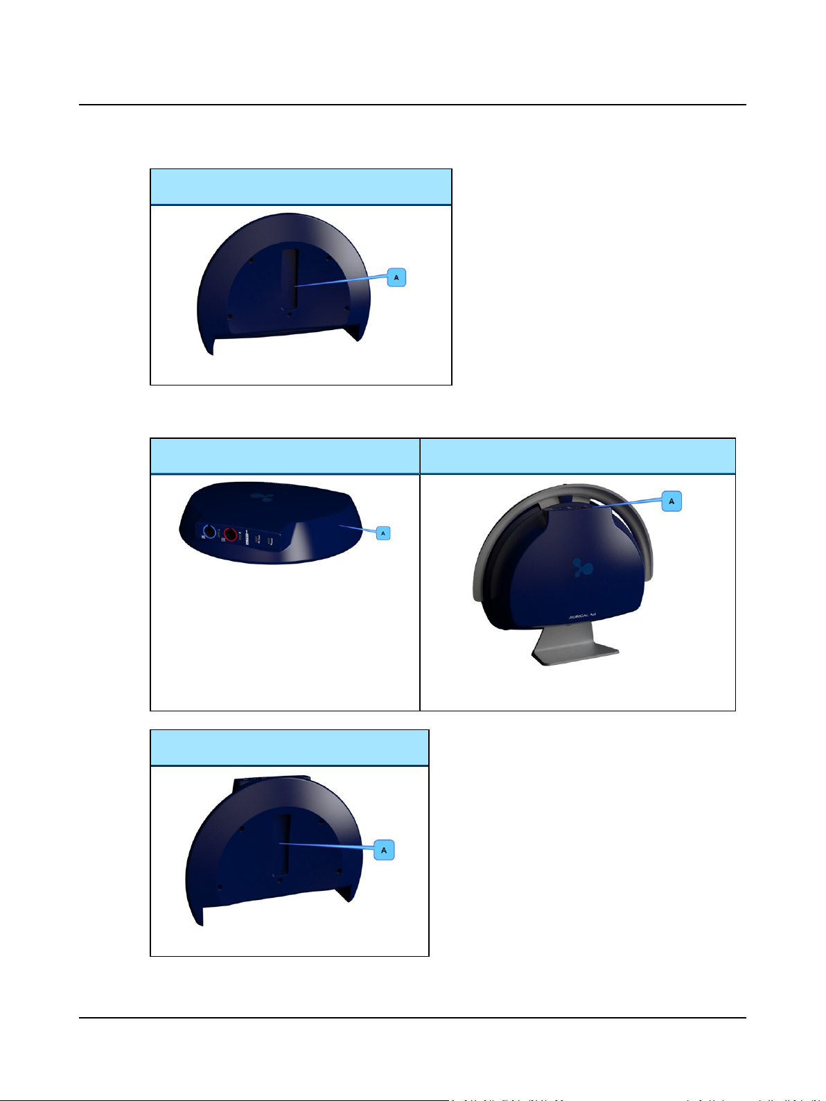
Rear view - for attaching to mounting plate
A. Slot for attaching to mounting plate
5.4.2 AURICAL Aud - with HI-PRO2
Desktop version Mounted on AURICAL speaker unit
5 Unpacking and Installing
A. AURICAL Aud with HI-PRO2
Rear view - for attaching to mounting plate
A. Slot for attaching to mounting plate
Otometrics - AURICAL Aud
A. HI-PRO2 power indicator and connectors for hearing
instrument connection cables
87
Page 88
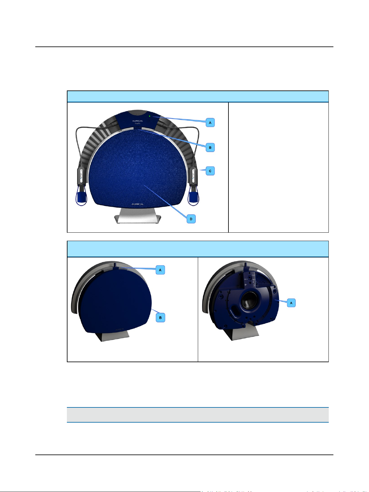
5 Unpacking and Installing
5.4.3 AURICAL speaker unit
AURICAL speaker unit with AURICALFreeFit
A. Status indicator - AURICALFreeFit
B. On/off indicator - AURICAL speaker
unit
C. AURICALFreeFit
D. AURICAL speaker unit with speaker
cover in place
AURICAL speaker unit
A. Charger for AURICALFreeFit
B. AURICAL speaker unit with speaker cover in place
5.5 Connection panels
5.5.1 AURICALAud connection panel
Caution• Install OTOsuite on the PC before you connect to AURICAL Aud from the PC.
A. AURICAL speaker unit with speaker cover removed
88 Otometrics - AURICAL Aud
Page 89
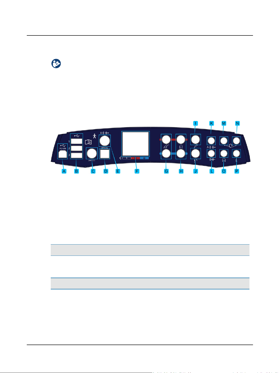
5 Unpacking and Installing
The installation must be carried out in accordance with IEC 60601-1-1 plus addendum in the form of Part 1:
General provisions -1 and UL 60601-1, CAN/CSA-C22.2 NO 601.1-90. The supplementary provisions on the reliability of electro-medical systems.
It is a general rule for all electrical equipment used in the proximity of the client that:
• The connected equipment must comply with IEC 60601-1 and/or IEC 60601-1-1
except for the PC, and equipment connected to the line in and the line out sockets of AURICAL Aud.
See also Warning notes ► 115.
When you have connected the accessories, configure your system setup. To do so, see Configuring the Audiometry Mod-
ule ► 101.
A. PC/USB connection ► 89
B. Powered USB connections for accessories ► 90
C. External power supply ► 90
D. Sound field speaker output (optical digital line-out)
► 90
E. Sound field speaker output (coaxial digital line-out)
► 90
F. Sound field speakers (built-in amplifier output) ►
90
G. Insert earphones ► 91
H. Headphones - air conduction ► 91
I. Patient Responder ► 91
J. Bone oscillator ► 91
K. Speaker, Analog (line output) ► 91
L. Line-in ► 91
M. Operator monitor headset - headphones ► 91
N. Operator monitor headset - boom microphone ►
91
O. Counseling and Simulations headphones ► 91
P. Talk-back microphone ► 91
Note•Blue corresponds to Left and red corresponds to Right.
PC/USB connection
Caution• Install OTOsuite on the PC before you connect to AURICAL Aud from the PC.
To connect AURICAL Aud to a PC, use the supplied USB cable.
1. Plug one end of the USB cable into the PC/USB socket in the connection panel and the other into a USB socket on the
PC.
2. Switch on AURICAL Aud. The driver installation will be initiated.
3. If the Found New Hardware Wizard appears on the screen, click the radio button No, not this time and click Next.
Otometrics - AURICAL Aud
89
Page 90

5 Unpacking and Installing
4. Follow the on-screen instructions.
Powered USB connections for accessories
Caution• Install the OTOsuite Audiometry Module on the PC before you connect AURICAL Aud to the PC.
These USB connections are powered up to 500 mA, so that, for instance, you can connect the USB double-cable version of
OTOcam to two of these USB connections.
To connect accessories to AURICAL Aud, use the supplied USB cable(s).
1. Plug one end of the USB cable(s) into the USB socket in the connection panel and the other end into a USB socket on
the accessory.
External power supply
Warning • Use only the power supply provided by Otometrics.
Warning • AURICAL Aud is not provided with a mains switch.
To connect AURICAL Aud to the mains supply, plug the mains plug into the wall mains outlet.
To disconnect AURICAL Aud from the mains supply, pull the mains plug out of the wall mains outlet. Do not position the unit so that it is difficult to pull the mains plug out of the wall mains.
See Power supply ► 127 for details.
1. Plug the external power supply into the Power socket in the connection panel.
2. Plug the mains plug of the external power supply into an AC mains outlet with a three-wire protective ground.
Sound field speaker output (optical digital line-out)
Optical connection for connecting to an external amplifier for sound field speaker(s). (Currently not in use.)
Sound field speaker output (coaxial digital line-out)
Coaxial connection for connecting to an external amplifier for sound field speaker(s). (Currently not in use.)
Sound field speakers (built-in amplifier output)
Connections for the AURICAL speaker unit and the PMM sound field speakers using the built-in amplifiers (2 sound field
speakers are supported in the software).
• Plug the AURICAL speaker unit into socket no. 3.
• If you are using two sound field speakers in addition to or instead of the AURICAL speaker, plug the cable of the left
speaker into socket no. 1, and the cable of the right speaker into socket no. 2.
• If you are using two sound field speakers in addition to or instead of the AURICAL speaker, set up the configuration in
the Configuration Wizard in OTOsuite. See Configuring the Audiometry Module ► 101.
90 Otometrics - AURICAL Aud
Page 91
Note•Sound-field testing is not available on some models.
Insert earphones
• Plug the insert earphones into the Right and Left Insert sockets.
• If you are using a mono insert earphone, plug it into the Left Insert socket (the lower socket).
Headphones - air conduction
• Plug standard headphone cables (red and blue jacks) into the Right and Left Headphone sockets.
Patient Responder
• If you are using a Patient Responder, plug it into this socket.
Bone oscillator
• Connection for a standard Bone Oscillator for Mastoid or Forehead placement.
Speaker, Analog (line output)
• Connection for a sound field speaker with external amplifier. (Not active on some models.)
5 Unpacking and Installing
Line-in
• Connection for a line-in device (e.g. CD player).
Caution• When you connect other electrical equipment to AURICAL Aud, remember that equipment that does not
comply with the same safety standards as AURICAL Aud can lead to a general reduction in the system's safety
level.
Operator monitor headset - headphones
• If you are using headphones with the operator monitor headset, plug the headphones into this socket.
The jack is marked with this symbol.
Operator monitor headset - boom microphone
• If you are using a boom microphone with the operator monitor headset, plug the boom microphone on the monitor
headset into this socket.
The jack is marked with this symbol.
Counseling and Simulations headphones
• Connection for Counseling and Simulations headphones.
Talk-back microphone
• Connection for an operator desktop microphone.
Otometrics - AURICAL Aud
91
Page 92
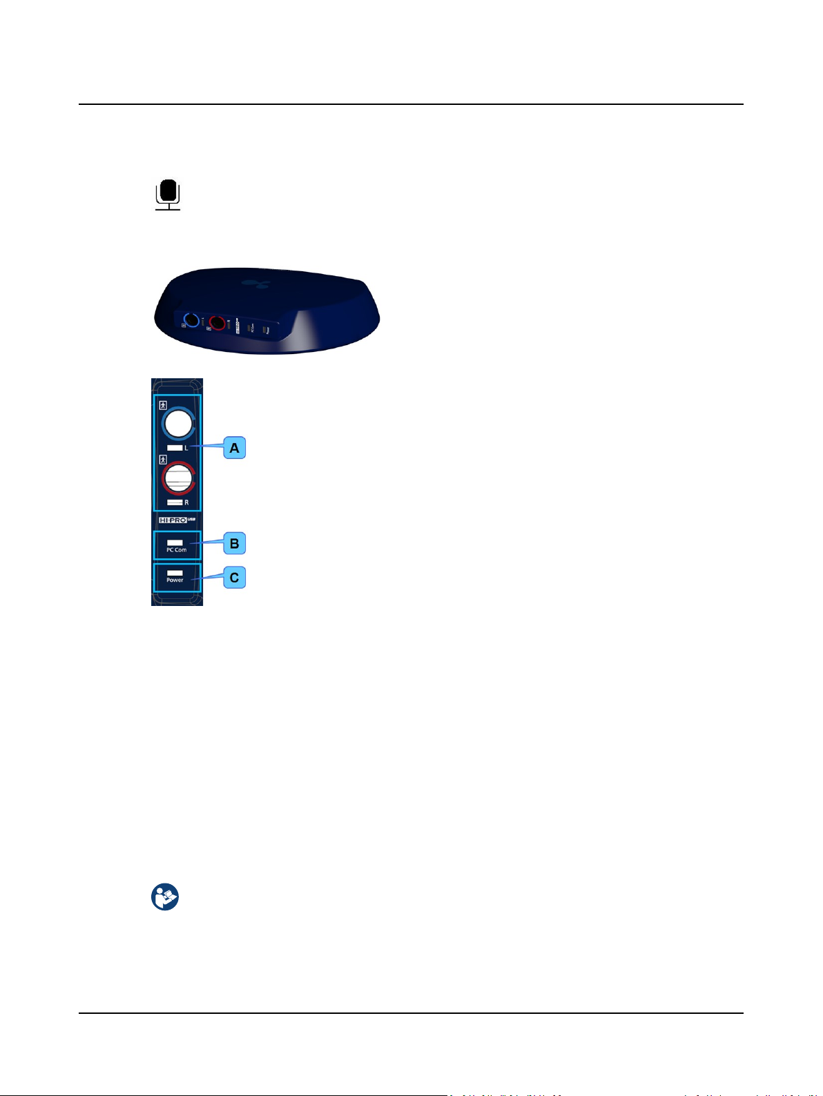
5 Unpacking and Installing
The jack is marked with this symbol.
5.5.2 Built-in HI-PRO2 connection panel
The HI-PRO2 connection panel contains the sockets for hearing
instrument connection cables, and light indicators relating to PC
communication and powering.
A. HI connection cables ► 92
B. PC Com light indicator ► 92
C. Power light indicator ► 92
HI connection cables
Sockets for connecting left and right hearing instrument connection cables. The cables are supplied by the hearing instrument manufacturer.
Connector light indicators are lit when a hearing instrument is being programmed, indicating which side is active.
For standards and warning notes see Standards and Safety ► 115.
PC Com light indicator
This light indicator lights up green during self-test when AURICAL Aud is powered on.
If the light indicator flashes, the self-test has failed, and there is a communication error.
Power light indicator
This light indicator lights up green when AURICAL Aud is powered on.
5.5.3 AURICAL speaker unit connection panel
The installation must be carried out in accordance with IEC 60601-1-1 plus addendum in the form of Part 1:
General provisions -1 and UL 60601-1, CAN/CSA-C22.2 NO 601.1-90. The supplementary provisions on the reliability of electro-medical systems.
92 Otometrics - AURICAL Aud
Page 93
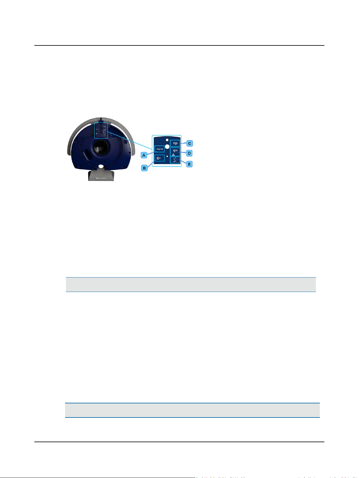
It is a general rule for all electrical equipment used in the proximity of the client that:
• The connected equipment must comply with IEC 60601-1 and/or IEC 60601-1-1
except for the PC, and equipment connected to the line in and the line out sockets of AURICAL Aud.
• To access the AURICAL speaker unit connection panel, remove the speaker cover.
A. USB ► 93
B. BT (Bluetooth) ► 93
C. 24V dc out ► 93
D. 24V dc in ► 93
E. Speaker input ► 93
5 Unpacking and Installing
USB
BT (Bluetooth)
• USB socket for connecting the speaker to the no. 3 USB socket on the
AURICAL Aud connection panel.
See AURICAL speaker unit installation ► 95.
• Socket for Bluetooth dongle.
Insert the Bluetooth dongle in this socket for communication between
AURICALFreeFit and the OTOsuite PMM module.
For a description of Bluetooth communication between PMM and
AURICALFreeFit, see the AURICALFreeFit User Manual.
Power supply connections
Caution• Install the OTOsuite Audiometry Module on the PC before you connect AURICAL Aud to the PC.
24V dc out
24V dc in
• Double-ended male connector for connecting the power supply to AURICAL
Aud.
See AURICAL speaker unit installation ► 95.
• Power supply connector for the external power supply of the AURICAL
speaker unit.
Speaker connection
Speaker input
• Sound field speaker connection to the AURICAL speaker unit from AURICAL
Aud.
See AURICAL speaker unit installation ► 95.
5.6 Assembling AURICAL Aud
Caution• Install the OTOsuite Audiometry Module on the PC before you connect AURICAL Aud to the PC.
Otometrics - AURICAL Aud
93
Page 94
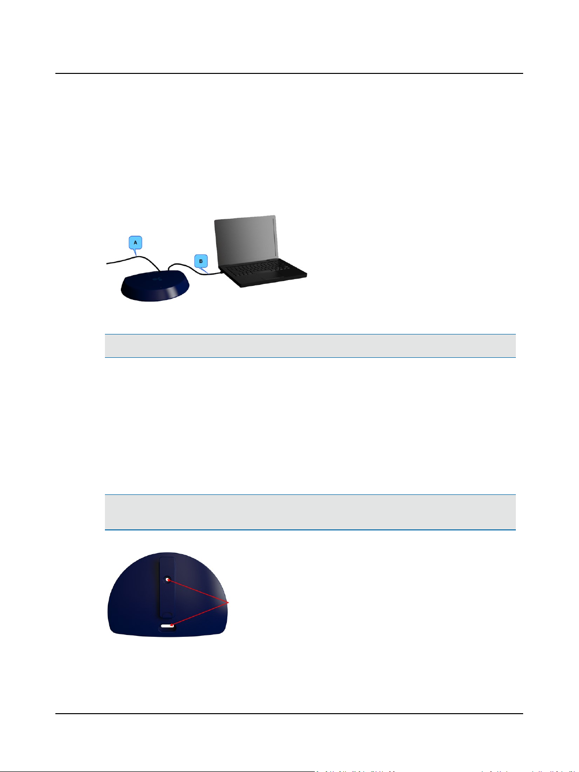
5 Unpacking and Installing
• Read the OTOsuite user documentation before you connect or use AURICAL Aud for the first time.
AURICAL Aud is fully assembled on delivery, and you simply have to connect cables.
If AURICAL Aud is to be mounted under the desk top or on the wall, mount the mounting plate under the desk or on the
wall, and click AURICAL Aud onto the mounting plate. See Desktop or wall installation ► 94.
5.7 Desktop or wall installation
A. External power supply cable
B. USB cable between AURICAL Aud and the PC
Note•Connection cables for accessories connected to AURICAL Aud are not shown. See Connection panels ► 88.
You can place AURICAL Aud on the desktop, or hang it under the desktop or on the wall.
On the desktop
1. Place AURICAL Aud on the desktop.
2. Follow the instructions in Connecting accessories and PC to AURICAL Aud ► 95.
Under the desktop or on the wall
Mount a mounting plate under the desktop or on the wall, and attach AURICAL Aud to the mounting plate.
Tools are needed for mounting the mounting plate.
Note•Make sure that you use screws specifically suited for the type of surface on which you will be hanging
AURICAL Aud.
1. Mount the mounting plate securely on the wall or under the desktop.
2. Fit the screws through the slots marked by the arrows.
3. Click AURICAL Aud onto the mounting plate.
94 Otometrics - AURICAL Aud
Page 95
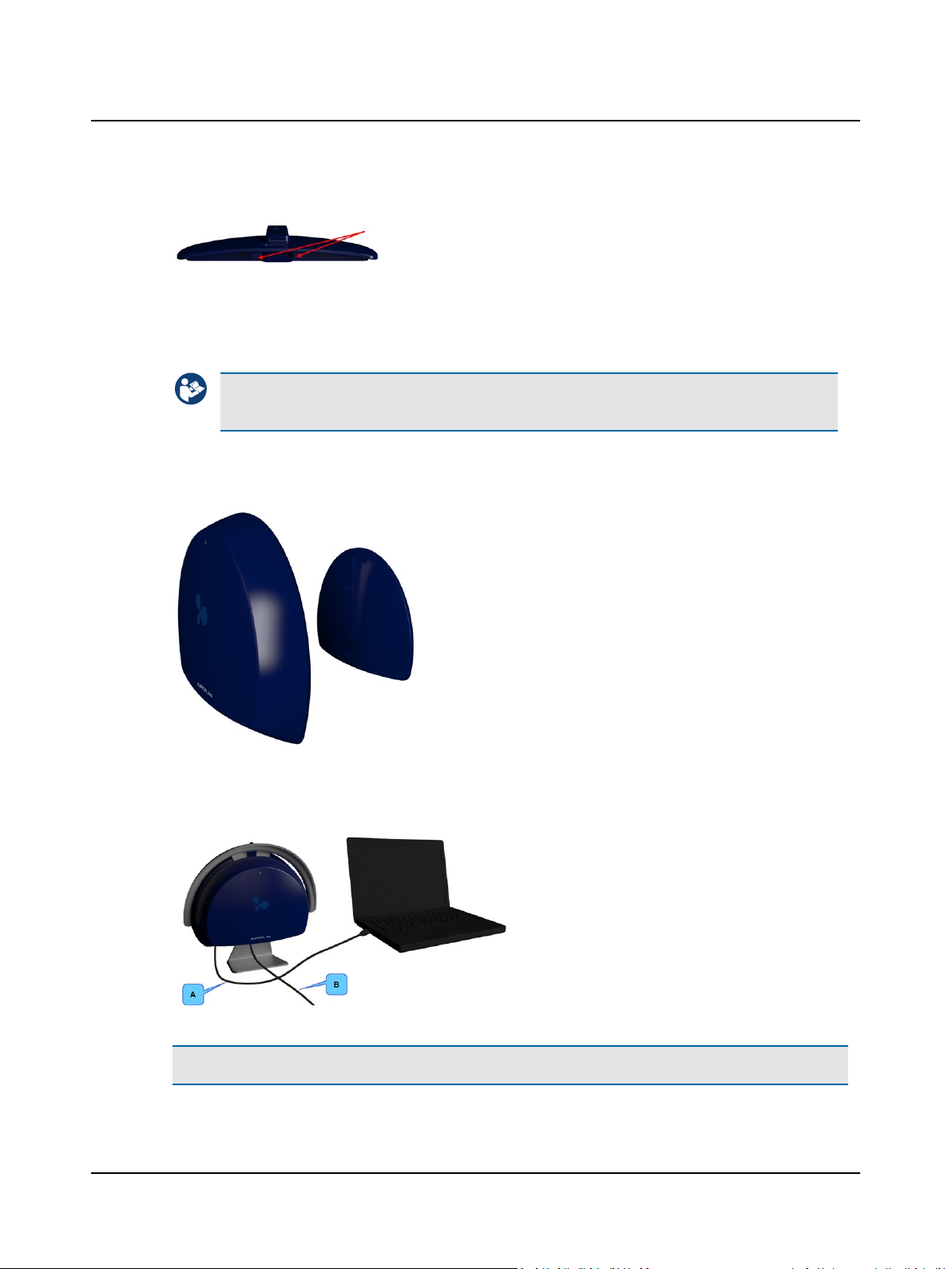
4. You can fit the power cable and the USB cable behind one of the
braces in order to keep them free of the cables for the accessories.
5.7.1 Connecting accessories and PC to AURICAL Aud
1. Connect the accessories to AURICAL Aud. See Connection panels ► 88 for a description of the connection panel.
2. Connect AURICAL Aud to the PC with the USB cable supplied.
Caution• To connect AURICAL Aud to the PC, use the supplied USB cable. The cable length must not
exceed 3 m (approx. 10 feet).
5.7.2 Mounting AURICAL Aud on the mounting plate
5 Unpacking and Installing
1. Click AURICAL Aud onto the mounting plate.
5.8 AURICAL speaker unit installation
Note•Connection cables for accessories connected to AURICAL Aud are not shown. See Connection panels ► 88.
Otometrics - AURICAL Aud
A. USB cable between AURICAL Aud and the PC
B. External power supply cable
95
Page 96
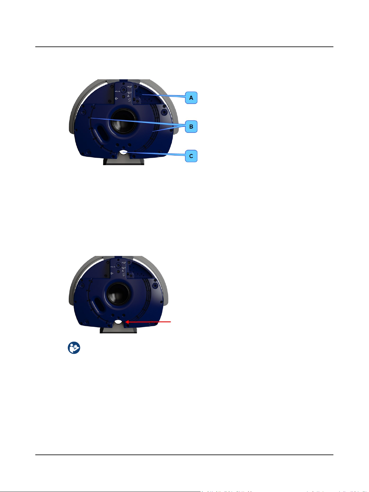
5 Unpacking and Installing
1. Remove the cover on the AURICAL speaker unit and connect the short connection cables between the AURICAL
speaker unit and AURICAL Aud as described in Connecting cables to the AURICAL speaker unit ► 96.
2. When you connect AURICAL Aud to the AURICAL speaker unit, gently press the cables into the cable guides on the
front of the speaker.
You can insert cable strips in the cable strip guides in order to hold the cables in place.
A. Guides for inserting cable strips
B. Cable guides
C. Opening for fitting cables through
5.8.1 Connecting cables to the AURICAL speaker unit
Connecting cables
The installation must be carried out in accordance with IEC 60601-1-1 plus addendum in the form of Part 1:
General provisions -1 and UL 60601-1, CAN/CSA-C22.2 NO 601.1-90. The supplementary provisions on the reliability of electro-medical systems.
It is a general rule for all electrical equipment used in the proximity of the client that:
• The connected equipment must comply with IEC 60601-1 and/or IEC 60601-1-1
except for the PC, and equipment connected to the line in and the line out sockets of AURICAL Aud.
See also Warning notes ► 115.
1. Fit the cables through the opening in the AURICAL
speaker unit below the speaker.
2. When you have connected all the cables to the
AURICAL speaker unit, place the speaker cover on
the speaker.
96 Otometrics - AURICAL Aud
Page 97
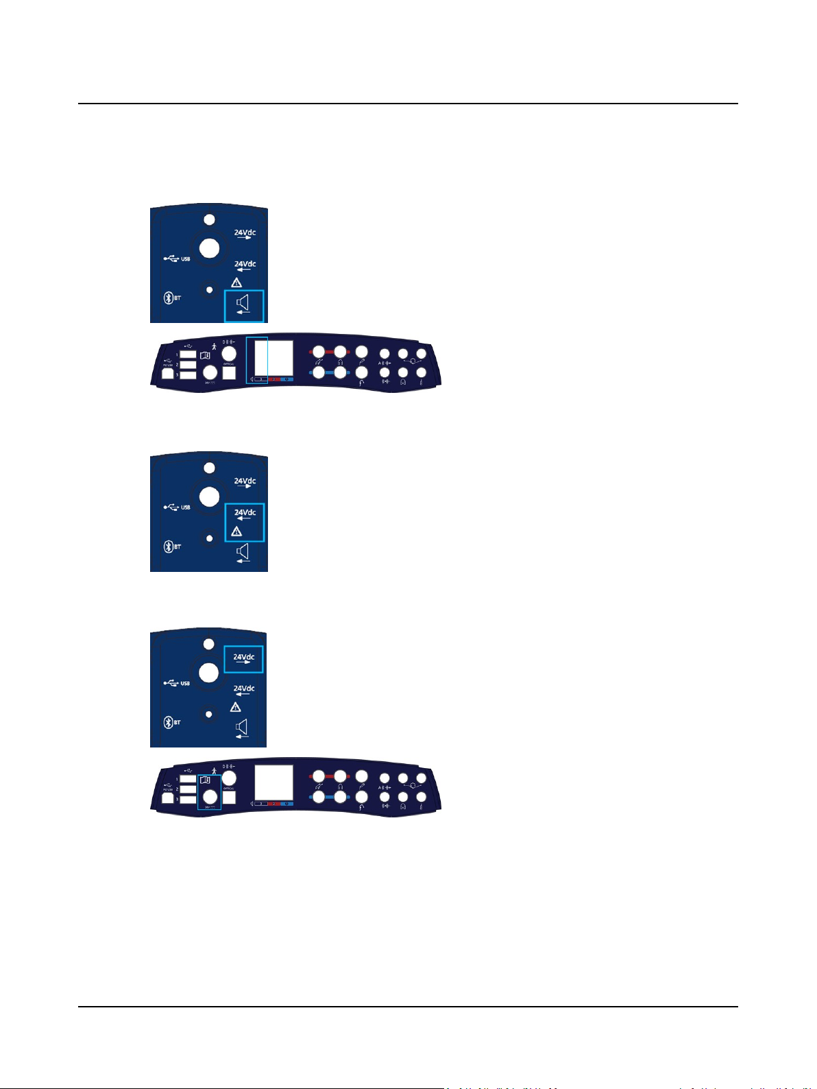
Connecting the speaker connection cable to AURICAL Aud
1. Plug the speaker connection cable into this socket.
2. Fit the cable in the left-most cable guide on the
3. Plug the other end of the connection cable from
24V DC external power supply cable
1. Plug the external power supply cable into this
2. Fit the cable in the center cable guide on the right
3. When you have completed connecting the cables,
5 Unpacking and Installing
right side of the speaker.
the AURICAL speaker unit into the no. 3 speaker
socket on the AURICAL Aud connection panel.
socket.
side of the speaker.
plug the external power supply cable into the
mains outlet.
Connecting the 24V DC power supply cable to AURICAL Aud
1. Plug the power supply cable between the speaker
2. Fit the cable in the right-most cable guide on the
3. Plug the other end of the power supply cable into
and AURICALAud into this socket.
right side of the speaker.
the 24V DC socket on the AURICALAud connection panel.
Otometrics - AURICAL Aud
97
Page 98
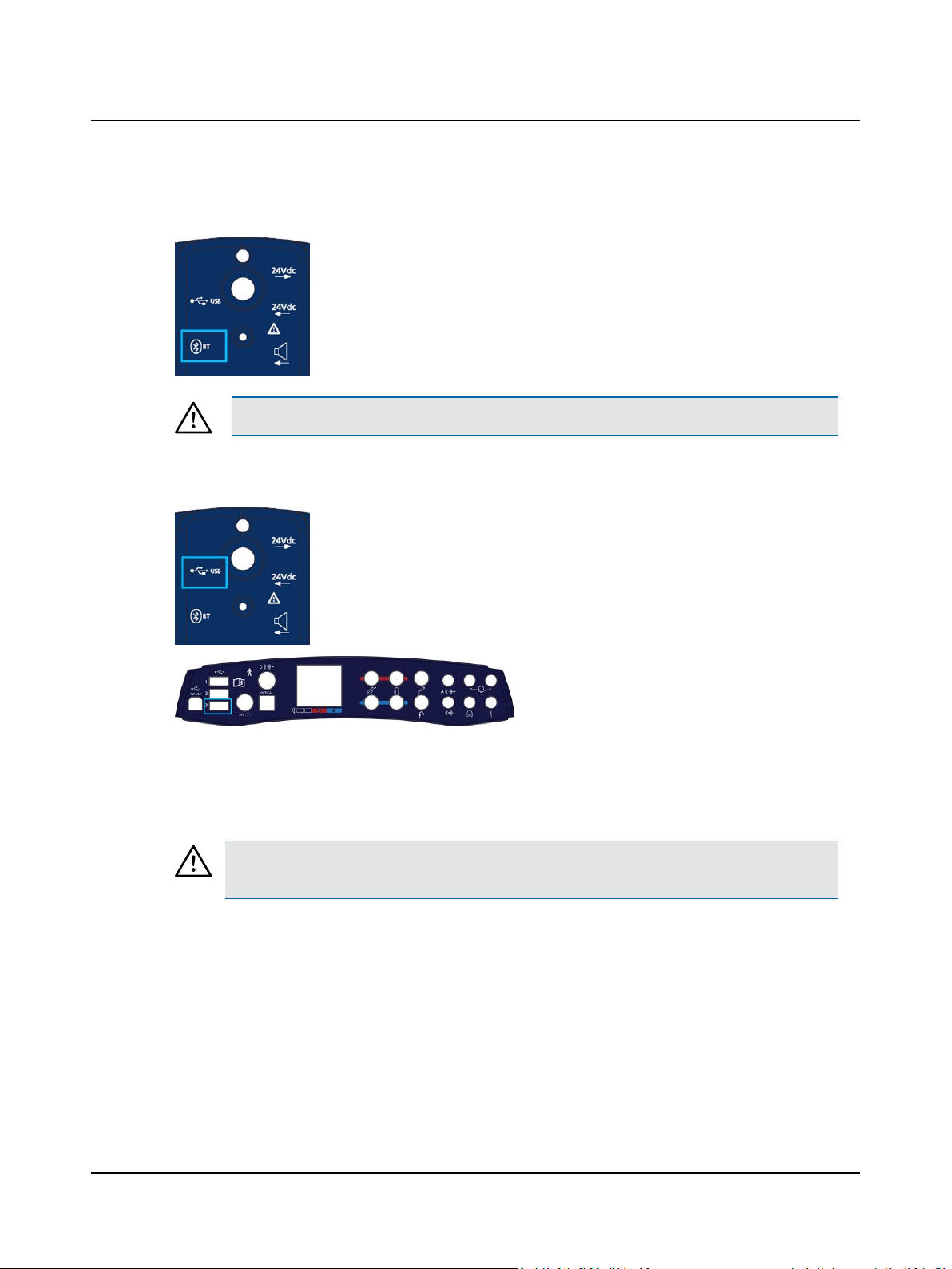
5 Unpacking and Installing
Bluetooth dongle
Connecting the USB connection cable to AURICAL Aud
1. If you are installing AURICALAud and the AURICAL
speaker unit for use with AURICAL FreeFit, insert
the Bluetooth dongle into this socket.
The Bluetooth dongle must comply with Otometrics requirements.
Caution• To connect the AURICAL speaker unit to AURICALAud, use the supplied USB cable.
1. Plug the AURICAL Aud USB connection cable into
this socket.
2. Fit the cable in the cable guide on the left side of
the speaker.
5.8.2 Connecting accessories and PC to AURICAL Aud
1. Connect the accessories to AURICAL Aud. See Connection panels ► 88.
2. Connect AURICAL Aud to the PC with the USB cable supplied.
Caution• To connect AURICAL Aud to the PC, use the supplied USB cable. The cable length must not
exceed 3 m (approx. 10 feet).
3. Plug the other end of the USB cable into USB
socket no. 3 on the AURICAL Aud connection
panel.
98 Otometrics - AURICAL Aud
Page 99
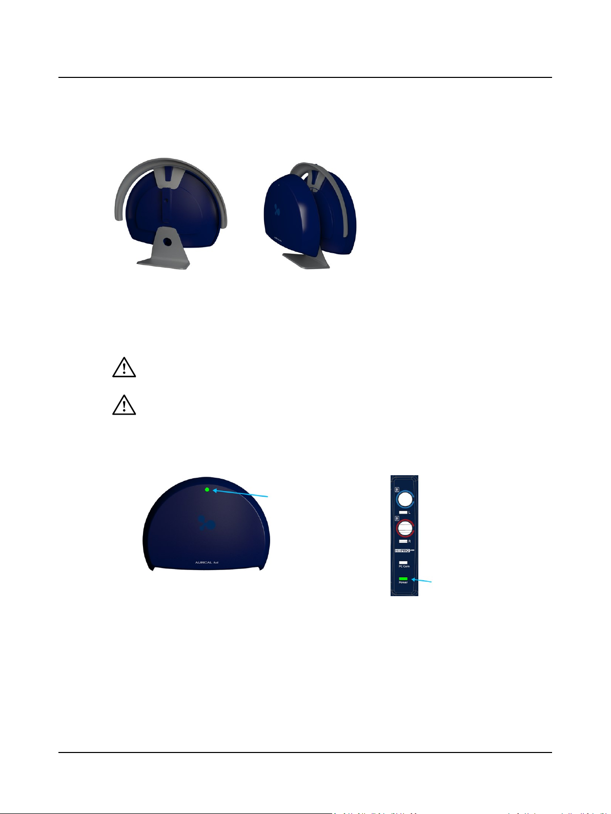
5.8.3 Mounting AURICAL Aud on the AURICAL speaker unit
5.9 Powering AURICAL Aud
AURICAL Aud is powered through an external power supply connected directly to the mains outlet.
Switching on AURICAL Aud
Use only the power supply specified in Technical Specifications, Power supply ► 127.
5 Unpacking and Installing
1. Click AURICAL Aud onto the mounting
plate on the rear of the AURICAL speaker
unit.
1. Connect the mains plug of the external power supply directly to an AC mains outlet with a three-wire
protective ground.
2. Switch on the mains supply.
3. The On/Off indicator on AURICAL Aud lights green.
AURICAL Aud AURICAL Aud with HI-PRO2
Switching off AURICAL Aud
1. To switch off AURICAL Aud, disconnect the power supply from the mains outlet.
Otometrics - AURICAL Aud
99
Page 100

5 Unpacking and Installing
100 Otometrics - AURICAL Aud
 Loading...