

Page 1
OPERATION MANUAL
Second Edition
Second Edition January, 1995 (JM)
Reprint April, 1996 (GK)
Printed in Japan
Part No. OS1-058
CLIP
0
-3
-6
-10
-14
-18
-25
-35
-45
-55
1
CLIP
0
-3
-6
-10
-14
-18
-25
-35
-45
-55
CLIP
0
-3
-6
-10
-14
-18
-25
-35
-45
-55
CLIP
0
-3
-6
-10
-14
-18
-25
-35
-45
-55
CLIP
0
-3
-6
-10
-14
-18
-25
-35
-45
-55
CLIP
0
-3
-6
-10
-14
-18
-25
-35
-45
-55
23456789101112131415161718192021222324
AUTO
PLAY
00:00:00:00.00
LOC:04 CHORUS 01
HRS/BAR MIN/BEAT SEC/STEP FRM SUB
MENU/
CANCEL
UP/
YES
DOWN/NOMARK
LOC
AUTO
INPUT
RECALL
LOC
EXT
SYNC
VARI-
SPEED
2nd
FUNC
AUTO
PUNCH
CYCLE
EDIT
LOC
UNDO/
REDO
CURS L CURS R
REC
RANDOM ACCESS DIGITAL AUDIO RECORDER
Page 2

CAUTION
PLEASE READ THROUGH THE SAFETY INSTRUCTIONS ON THE NEXT PAGE.
To prevent fire or shock hazard:
Do not expose this unit to rain or moisture.
Do not remove panels (unless instructed to do so).
There are no user-serviceable parts inside.
Refer servicing to qualified service personnel.
Edition 2 (Printed in Japan)
ii
Page 3

SAFETY INSTRUCTIONS
1. Read Instructions All safety and operating instructions should be read before operation.
2. Retain Instructions The safety and operating instructions should be retained for future
reference.
3. Heed Warnings All warnings on the device and in the operating instructions should be
complied with.
4. Follow Instructions All operating and use instructions should be followed.
5. Water and Moisture The device should not be used near water — for example, near a
bathtub, wash bowl, sink, laundry tub, in a wet basement, near a
swimming pool, etc.
6. Carts and Stands The device should be used only with a cart or stand that is
recommended by the manufacturer.
7. Ventilation The device should be situated so that its location or position does not
interfere with its proper ventilation. For example, the device should not
be situated on a bed, sofa, rug, or similar surface that may block the
ventilation openings; or , placed in a built-in installation, such as a
bookcase or cabinet that may impede the flow of air through the
ventilation openings.
8. Heat The device should be situated away from heat sources such as a radiator,
heat register, stove or other appliances (including amplifiers) that
produce heat.
9. Power Sources The device should be connected to a power supply only of the type
described in the operating instructions or as marked on the device.
10. Grounding or Polarization Precautions should be taken so that the grounding or polarization
means of the device is not defeated.
11. Power Cord Protection Power supply cords should be routed so that they are not likely to be
walked on or pinched by items placed upon or against them, paying
particular attention to cords at plugs, convenience receptacles, and the
point where they exit from the device.
12. Cleaning The device should be cleaned only as recommended by the
manufacturer.
13. Non-Use Periods The power cord of the device should be unplugged from the outlet
when left unused for a long period of time.
14 Object and Liquid Entry Care should be taken that objects do not enter and that liquids are not
spilled into the enclosure through openings.
15. Damage Requiring Service The device should be serviced by qualified service personnel when:
A. The power supply cord or the plug has been damaged; or
B. Objects have entered, or liquid has been spilled into the appliance;
or
C. The appliance has been exposed to rain; or
D. The appliance does not appear to operate normally or exhibits a
marked change in performance; or
E. The appliance has been dropped, or the enclosure damaged.
16. Servicing The user should not attempt to service the device beyond what is
described in the operating instructions. All other service should be
referred to qualified personnel.
Edition 2 (Printed in Japan)
RADAR OPERATION MANUAL iii
Page 4

COMMUNICATION WITH OTARI
FOR SERVICE INFORMATION AND PARTS
All Otari products are manufactured under strict quality control. Each unit is carefully inspected and tested prior
to shipment.
If, however, some adjustment or technical support becomes necessary, replacement parts are required, or technical
questions arise, please contact your Otari dealer or contact Otari at:
Otari, Inc. Otari Corporation
4-33-3 Kokuryocho, Chofu-shi, 378 Vintage Park Drive
182, Tokyo, Japan Foster City, California 94404
Telephone : (81) 42481-8626 U.S.A.
Fax : (81) 42481-8633 Telephone : (415) 341-5900
Telex : J26604 OTRDENKI Fax : (415) 341-7200
Cable : OTARIDENKI TOKYO
Otari Deutschland GmbH. Otari Singapore Pte., Ltd
Rudolf-Diesel-Str.12 40 MacTaggart Road
D-40670 Meerbusch (Osterath) Singapore 1336
F.R. Germany Telephone : (65) 284-7211
Telephone : (49) 2159-50861 Fax : (65) 284-4727
Fax : (49) 2159-1778 Telex : RS 36935 OTARI
Another part of Otari’s continuing technical support program for our products is the continuous revision of
manuals as the equipment is improved or modified. In order for you to receive the information and support
which is applicable to your equipment, and for the technical support program to function properly, please include
the following information, most of which can be obtained from the Serial number label on the machine, in all
correspondence with Otari:
• Model Number:
• Serial Number:
• Date of Purchase:
• Name and address of the dealer where the machine was purchased and the power requirements (voltage
and frequency) of the machine.
Edition 2 (Printed in Japan)
iv COMMUNICATION WITH OTARI
Page 5

FCC STATEMENT
This equipment has been tested and found to comply with the limits for a Class
B digital device, pursuant to Part 15 of the FCC Rules. These limits are
designed to provide reasonable protection against harmful interference in a
residential installation. This equipment generates, uses, and can radiate radio
frequency energy and, if not installed and used in accordance with the
instructions, may cause harmful interference to radio communications.
However, there is no guarantee that interference will not occur in a particular
installation. If this equipment does cause harmful interference to radio or
television reception, which can be determined by turning the equipment off and
on, the user is encouraged to correct the interference by one or more of the
following measures:
• Re-orient or relocate the receiving antenna
• Increase the separation between the equipment and the receiver
• Connect the equipment into an outlet on a circuit different from that which
the receiver is connected
• Consult the dealer or an experienced radio/TV technician for help
Shielded cables and I/O cords must be used with this equipment to comply
with the relevant FCC regulations.
Changes or modifications not expressly approved in writing by Otari, Inc. may
void the user’s authority to operate this equipment.
Edition 2 (Printed in Japan)
CANADIAN STANDARDS ASSOCIATION
ASSOCIATION CANADIENNE DE NORMALISATION
✣This product has been found to comply with all applicable CSA standards
CERTIFICATIONS
UNDERWRITER’S LABORATORIES
This product has been found to comply with all applicable UL standards
RADAR OPERATION MANUAL v
Page 6

LIMITED WARRANTY
The RADAR system and RE-8 session controller are warranted from the
date of purchase to the original purchaser to be free from defects in
material or workmanship for a period of one (1) year.
The hard disk drives contained within the RADAR chassis are warranted
for a period of one (1) year.
This warranty does not apply to damage resulting from improper or
negligent use, inadequate or improper packaging for shipment, damage
incurred during shipment, or unauthorized modification.
The sole and exclusive remedy for breach of any warranty concerning the
RADAR system, RE-8 session controller, and supplied internal hard disk
drives shall be repair or replacement of defective parts at the discretion of
Otari, Inc.
Repair or replacement of RADAR and/or RE-8 components will be
performed at no charge for parts or labor for one (1) year from date of
purchase to the original purchaser at a designated Otari service center or
the factory, at Otari’s discretion. Repair or replacement of the hard disk
drives contained within the RADAR system will be performed at no
charge for parts or labor for one (1) year from the date of purchase to the
original purchaser at a designated Otari service center or the factory, at
Otari’s discretion.
Otari, Inc. disclaims any warranty, expressed or implied of suitability for
specific use and disclaims any liability for incidental, special, or
consequential damages.
Edition 2 (Printed in Japan)
vi LIMITED WARRANTY
Page 7

Please Read this First...
Congratulations on the purchase of your new RADAR system!
In order for Otari to maintain contact with you regarding new system features
for your RADAR machine and to provide you with the best service possible, we
ask that you take a moment to fill out the form below and return it to us as soon
as possible. Our address is:
Otari, Inc.
4-33-3 Kokuryocho, Chofu-shi
182, Tokyo, JAPAN
Attn: RADAR Service Department
RADAR User Information
Company:
__________________________________________________
Contact:
__________________________________________________
Address:
__________________________________________________
City: _______________________ State & ZIP: __________
Phone: _______________________ Fax: _________________
Dealer:
__________________________________________________
Purchase Date:
__________________________________________________
RADAR S/N:
__________________________________________________
RE-8 S/N:
__________________________________________________
EXB-5G S/N:
__________________________________________________
EDB-3 S/N:
__________________________________________________
Type of Business
(Please check all that apply)
___Music Recording ___TV Production ___Film P roduction
___Broadcasting ___Other (describe) ____________________
____________________________________
____________________________________
____________________________________
Page 8

TO ALLOW US TO
SERVE YOU WITH THE
BEST CUSTOMER
SUPPORT POSSIBLE,
PLEASE TAKE THE TIME
TO FILL OUT AND
RETURN THE USER
INFORMATION FORM
ON THE REVERSE SIDE
OF THIS PAGE.
THANK YOU !
Page 9

Edition 2 (Printed in Japan)
Communication with Otari ..........................................iv
Certifications .......................................................v
Section 1 Welcome to RADAR!
1.1 INTRODUCTION
............................................1-2
1.2 RADAR SYSTEM FEATURES....................................1-2
1.3 AN OVERVIEW OF HARD DISK RECORDING ..................1-3
1.4 MANUAL OVERVIEW ........................................1-4
1.5 RADAR HARDWARE SPECIFICATIONS.........................1-4
1.5.1 AC Power..........................................1-4
1.5.2 Audio Inputs & Outputs ..............................1-5
1.5.3 Input & Output Reference Levels ......................1-5
1.5.4 Grounding .........................................1-6
1.6 CONTROLS & INDICATORS ..................................1-7
1.6.1 Rear Panel Connectors ..............................1-7
1.6.2 Front Panel Controls & Indicators .....................1-8
1.7 IMPORTANT INITIAL INFORMATION ..........................1-9
Section 2 Product Overview/Getting Started!
2.1 INTRODUCTION
............................................2-2
2.2 BEFORE STARTING—PLEASE READ THIS! ......................2-2
2.2.1 AC Power Level Setting..............................2-2
2.2.2 SCSI Terminator Installation...........................2-2
2.3 AUDIO INPUTS/OUTPUTS....................................2-3
2.3.1 About Audio Reference Levels ........................2-3
2.3.2 Audio Connections—Analog.........................2-3
2.3.3 Audio Connections—Digital..........................2-4
2.4 POWER ON/OFF PROCEDURE...............................2-5
2.4.1 Power Up Procedure ................................2-5
2.4.2 Power Down Procedure..............................2-5
2.5 ARMING TRACKS OVERVIEW ................................2-6
2.6 RECORDING & PLAYBACK OVERVIEW ........................2-6
2.7 LOCATING IN THE RECORDED AUDIO........................2-7
2.7.1 Locating Using Fast Wind Keys.......................2-7
2.7.2 Jog/Shuttle Operation (RE-8 Only) ....................2-7
2.7.2.1 Entering Jog Mode...............................2-7
2.7.2.2 Entering Shuttle Mode ............................2-8
2.8 DISK TIME AVAILABLE.........................................2-8
2.9 NAVIGATING RADAR’S MENU ...............................2-9
2.9.1 Menus Overview ...................................2-9
Table of Contents
Page 10

2.9.2 Moving Around in Menus............................2-9
2.9.2.1 Menu Operation Using the RE-8....................2-9
2.9.2.2 Front Panel Menu Operation.......................2-9
2.9.3 Navigating the Menu ..............................2-10
2.9.4 Menu Structure.....................................2-10
2.10 RADAR PROJECTS OVERVIEW ..............................2-11
2.10.1 Default Project....................................2-11
2.10.2 Creating a New Project...........................2-11
2.10.3 Switching Between Projects........................2-11
2.10.4 Naming Projects..................................2-12
2.10.5 Copying Projects .................................2-12
2.10.6 Project Start Time .................................2-12
2.10.7 Project Sample Rate...............................2-12
2.10.8 Deleting Projects..................................2-12
2.10.9 Reclaiming Disk Space from Deleted Project(s).......2-13
2.11 EDITING/AN OVERVIEW..................................2-14
2.10.1 Edit Markers (MARK IN, MARK OUT)...............2-14
2.10.2 RADAR’s Editing Clipboard ........................2-14
Section 3 Recording & Transport Operation
3.1 GENERAL
...................................................3-3
3.2 ARMING TRACKS FOR RECORD ..............................3-3
3.3 INPUT MONITORING/METERS DISPLAY.......................3-4
3.3.1 Peak Hold Indicators ................................3-4
3.3.2 Clip Indicator LEDs..................................3-4
3.4 SAMPLE RATE SELECTION ...................................3-5
3.4.1 Sampling Rate Overview ............................3-5
3.4.2 Changing RADAR’s Sample Rate......................3-5
3.5 RECORDING OPERATION....................................3-6
3.5.1 Entering Record.....................................3-6
3.5.2 Punching In on Additional Tracks .....................3-6
3.5.3 Punch Out (Dropping Out of Record)..................3-6
3.5.4 Record Safe Feature.................................3-8
3.5.5 Clear Rec-Ready (RE-8 Only) .........................3-8
3.5.6 Recording to Timecode ..............................3-8
3.6 PLAYBACK OPERATION ......................................3-8
3.6.1 Standard Playback..................................3-8
3.6.2 Reverse Playback ...................................3-8
3.6.3 Playback Locked to Timecode ........................3-8
3.7 TRACK SOLO FEATURE (RE-8 Only) ............................3-9
3.7.1 Additive Solo Mode Operation.......................3-9
3.7.2 Interlock Solo Mode Operation.......................3-9
3.7.3 Momentary Solo Mode Operation....................3-9
3.8 VARISPEED RECORDING/PLAYBACK .........................3-10
3.8.1 Varispeed Overview................................3-10
3.8.2 Changing Pitch with Varispeed ......................3-10
3.8.3 Changing Varispeed Units ..........................3-10
Edition 2 (Printed in Japan)
x TABLE OF CONTENTS
Page 11

3.9 AUTO INPUT MODE ........................................3-11
3.9.1 Auto Input Overview ...............................3-11
3.9.2 Turning Auto Input On & Off ........................3-11
3.10 AUTO PUNCH MODE.....................................3-12
3.10.1 Setting Up for an Auto Punch ......................3-12
3.10.2 Editing Auto Punch In and Out Locations ............3-13
3.11 UNDO/REDO FUNCTIONS ...............................3-13
3.12 LOCATING IN THE RECORDED MATERIAL...................3-14
3.12.1 Cueing with Fast-Forward and Rewind..............3-14
3.12.2 Jog/Shuttle Mode (RE-8 Only) .....................3-14
3.13 AUTO LOCATION .........................................3-16
3.13.1 Programming a New Auto Locate Point .............3-16
3.13.2 Recalling Marked Locate Points from the Front Panel. . 3-16
3.13.3 Recalling a Locate Point from the RE-8 ..............3-16
3.13.4 Auto Play After Locate.............................3-17
3.13.5 Editing a Locate, Mark In, or Mark Out Point........3-18
3.13.6 Naming Locate Points from the Front Panel ..........3-19
3.14 LOCATING VIA DIRECT TIME ENTRY (RE-8 Only) .............3-20
3.15 CYCLE....................................................3-21
3.16 PRE/POST ROLL ...........................................3-22
3.17 DIGITAL I/O OPERATION ..................................3-23
Section 4 RADAR Menu Operation
4.1 GENERAL
...................................................4-3
4.2 MENUS OVERVIEW..........................................4-3
4.2.1 RADAR Menu—Top Level ............................4-3
4.2.2 Moving Around in Menus............................4-3
4.2.2.1 Menu Operation using the RE-8 ....................4-3
4.2.2.2 Front Panel Menu Operation.......................4-3
4.2.3 Menu Structure......................................4-4
4.2.4 Entering/Exiting the Menu ...........................4-5
4.2.5 Scrolling & Selecting within the Menu.................4-6
4.2.6 Editing Values in a Dialog Window...................4-6
4.3 A TOUR OF THE MENU......................................4-7
4.3.1 System Menu .......................................4-7
4.3.1.1 System Version..................................4-7
4.3.1.2 Digital I/O.....................................4-7
4.3.1.3 Sync Output ....................................4-7
4.3.1.4 Configure Disks .................................4-7
4.3.1.5 Set Time & Date.................................4-8
4.3.1.6 Upgrade System.................................4-8
4.3.2 Project Menu .......................................4-8
4.3.2.1 Backup/Restore.................................4-8
4.3.2.2 GOTO Project ..................................4-8
4.3.2.3 Create Project...................................4-9
4.3.2.4 Name Project...................................4-9
Edition 2 (Printed in Japan)
RADAR OPERATION MANUAL xi
Page 12

4.3.2.5 Copy Project....................................4-9
4.3.2.6 Delete Project...................................4-9
4.3.2.7 Sample Rate....................................4-9
4.3.2.8 Start Time ......................................4-9
4.3.2.9 Sync Offset.....................................4-9
4.3.2.10 Reclaim Space................................4-10
4.3.2.11 Renumber Locates .............................4-10
4.3.2.12 Erase All Disks ................................4-10
4.3.3 Edit Menu.........................................4-11
4.3.3.1 Undo/Redo ...................................4-11
4.3.3.2 Modify Edit....................................4-11
4.3.3.3 Edit Features (Cut/Copy/Paste/Move/Erase/Loop
/Slide/Reverse)................................4-11
4.3.3.4 Listen.........................................4-11
4.3.3.5 Mute Tracks ...................................4-11
4.3.3.6 Import *.WAV Files.............................4-12
4.3.3.7 Crossfade Time ................................4-12
4.3.3.8 Record Safe ...................................4-12
4.3.4 Preferences Menu..................................4-13
4.3.4.1 Default SMPTE Field ..........................4-13
4.3.4.2 SMPTE Lock Speed .............................4-13
4.3.4.3 Track Solo Mode...............................4-13
4.3.4.4 Low Disk Warning..............................4-14
4.3.4.5 Slide Time Units ................................4-14
4.3.4.6 Record Mode..................................4-14
4.3.4.7 Fast Forward/Rewind Rate.......................4-15
4.3.4.8 Peak Hold Time ................................4-15
4.3.4.9 Clip Hold Time.................................4-15
4.3.4.10 Save State Delay..............................4-15
4.3.5 Diagnostics Menu..................................4-16
4.3.5.1 Scan SCSI Bus.................................4-16
4.3.5.2 Mount / Unmount (File System)....................4-16
4.3.5.3 Disk Diagnostics................................4-16
4.3.5.4 Show Free RAM................................4-16
4.3.5.5 Debug/Error Logging ...........................4-16
4.3.6 Shutdown RADAR ..................................4-17
Section 5 External Synchronization Features
5.1 GENERAL
...................................................5-2
5.1.1 Synchronization Overview ...........................5-2
5.1.2 SMPTE Overview ...................................5-2
5.1.2.1 SMPTE Frame Rates..............................5-3
5.1.2.2 Chasing a Variable Speed Timecode Source.........5-3
5.1.2.3 Recording to Timecode ...........................5-3
5.1.3 MIDI Timecode Sync Overview.......................5-4
5.1.4 Video Reference (House Sync) Overview ..............5-4
5.1.5 External Word Clock Overview ......................5-4
5.2 EXTERNAL SYNC CONNECTIONS ...........................5-5
5.2.1 Timecode Connections ..............................5-5
5.2.1.1 Timecode Input..................................5-5
5.2.1.2 Timecode Generator Output.......................5-5
5.2.2 MIDI Timecode (MTC) Connections...................5-5
Edition 2 (Printed in Japan)
xii TABLE OF CONTENTS
Page 13

5.2.3 Video Sync Connections.............................5-5
5.2.4 Digital Wordclock Connections ......................5-5
5.3 SMPTE TIMECODE OPERATION ..............................5-6
5.3.1 Setup for Timecode Operations.......................5-6
5.3.2 Recording While Locked to Timecode.................5-7
5.3.3 Playback to Timecode ...............................5-7
5.3.4 SMPTE Offset.......................................5-7
5.4 EXTERNAL SYNC (HOUSE SYNC) OPERATION ................5-8
5.5 DIGITAL WORDCLOCK OPERATION ..........................5-9
Section 6 RE-8 Session Controller Features
6.1 INTRODUCTION
............................................6-2
6.2 A TOUR OF THE RE-8 SESSION CONTROLLER.................6-2
6.2.1 Track Arm Keys...........................................6-2
6.2.2 Track Function Keys .......................................6-2
6.2.2.1 REC SAFE......................................6-2
6.2.2.2 TRACK SOLO...................................6-2
6.2.2.3 AUTO INPUT ...................................6-3
6.2.3 Text Entry Keys ...........................................6-3
6.2.4 LCD & Numeric Display....................................6-3
6.2.4.1 LCD...........................................6-3
6.2.4.2 2-Digit LED Display ..............................6-3
6.2.5 Calculator Keys ..........................................6-4
6.2.5.1 Numeric Keypad ................................6-4
6.2.5.2 + (Plus) and – (Minus) Keys........................6-4
6.2.5.3 MENU/PREV Key ...............................6-4
6.3.5.4 ENTER Key.....................................6-5
6.3.5.5 RECALL LOC Key................................6-5
6.3.5.6 ENTER TIME Key ................................6-5
6.2.6 Transport Keys ...........................................6-5
6.2.7 Cursor Keys..............................................6-5
6.2.8 Utility Keys...............................................6-6
6.2.9 RE-8 Dedicated Editing Keys................................6-7
6.2.10 Jog/Shuttle Wheel.......................................6-7
6.2.10.1 Entering Jog Mode .............................6-7
6.2.10.2 Entering Shuttle Mode...........................6-8
6.2.11 MARK IN & MARK OUT Keys .............................6-8
6.2.11.1 Defining a Location using MARK IN ...............6-8
6.2.11.2 Defining a Location using MARK OUT..............6-8
6.2.11.3 Recalling & Editing a Marked Location Point ........6-9
6.3 FOOT SWITCH FEATURES....................................6-9
Section 7 RADAR Editing Features
7.1 INTRODUCTION
............................................7-2
7.1.1 RADAR v1.1 Editing Functions ...........................7-2
7.1.2 About the Clipboard ....................................7-3
7.1.3 Digital Crossfades on Edit Operations ....................7-3
7.2 DEFINING AN AUDIO CLIP USING MARK IN/MARK OUT .....7-4
7.2.1 Marking the Start and End of an Audio Clip...............7-4
Edition 2 (Printed in Japan)
RADAR OPERATION MANUAL xiii
Page 14

7.2.2 Selecting Track(s) for Editing .............................7-4
7.2.3 Auditioning the Clipboard ...............................7-4
7.3 UNDO/REDO FUNCTIONS..................................7-5
7.4 CUT ........................................................7-6
7.5 COPY.......................................................7-7
7.6 PASTE .......................................................7-8
7.7 ERASE......................................................7-10
7.8 MOVE .....................................................7-11
7.9 SLIDE.......................................................7-13
7.10 LOOP.....................................................7-14
7.11 MODIFY EDIT .............................................7-15
7.12 REVERSE (REVERSE CLIPBOARD MATERIAL) ...................7-16
7.13 MUTE TRACKS ............................................7-17
7.14 IMPORT *.WAV TRANSLATOR FEATURE .....................7-18
Section 8 Backup & Restore Operation
8.1 BACKUP/RESTORE OVERVIEW
...............................8-2
8.2 EXABYTE DRIVE INSTALLATION/HOOKUP .....................8-3
8.3 BACKUP OPERATION ........................................8-4
8.4 RESTORE OPERATION........................................8-6
8.5 TAPE DRIVE ACTIVITY INDICATORS............................8-7
8.6 EXABYTE DRIVE CLEANING PROCEDURE ......................8-8
8.7 BACKUP/RESTORE ERROR MESSAGES........................8-9
Appendix A Hardware/Software Installation
A.1 INTRODUCTION
............................................A-2
A.2 RADAR PHYSICAL INSTALLATION..............................A-2
A.2.1 Rack Size ...............................................A-2
A.2.2 Rack Mounting...........................................A-2
A.2.3 Airflow/Cooling..........................................A-2
A.2.4 Rough Handling..........................................A-2
A.2.5 AC Power Level Setting....................................A-2
A.2.6 Grounding ..............................................A-3
A.3 CONTROLS & INDICATORS OVERVIEW.......................A-4
A.3.1 Rear Panel Connectors.....................................A-4
A.3.2 RADAR Front Panel Controls & Indicators......................A-6
A.4 ELECTRICAL INSTALLATION ...................................A-7
A.4.1 Audio Inputs & Outputs Overview............................A-7
A.4.1.1 Balanced vs. Unbalanced Audio Signals ................A-7
Edition 2 (Printed in Japan)
xiv TABLE OF CONTENTS
Page 15

A.4.1.2 Wiring for Balanced and Unbalanced Cables ...........A-7
A.4.1.3 Audio Reference Levels (-10 dBm/+4 dBu) ..............A-7
A.4.2 Audio Connections—Analog ...............................A-8
A.4.3 Audio Connections—Digital ................................A-8
A.4.4 External Sync Connections .................................A-9
A.4.4.1 Timecode Connections...............................A-9
A.4.4.2 Timecode Input .....................................A-9
A.4.4.3 Timecode Generator Output ..........................A-9
A.4.4.4 MIDI Timecode (MTC) Connections ....................A-9
A.4.4.5 Video Sync Connections .............................A-9
A.4.4.6 Digital Word Clock Connections ......................A-9
A.4.5 External SCSI Device Installation............................A-10
A.4.5.1 SCSI Basics.......................................A-10
A.4.5.2 SCSI Terminator Installation ..........................A-10
A.4.5.3 Backup Tape Drive Installation/Hookup................A-11
A.4.5.4 External Disk Drive Chassis Installation/Hookup .........A-12
A.5 SOFTWARE INSTALLATION ..................................A-12
A.5.1 Initial Installation Procedure................................A-12
A.5.2 Software Upgrade Installation Procedure.....................A-14
Appendix B Diagnostics
B.1 GENERAL
....................................................B-2
B.1.1 Diagnostics Introduction..............................B-2
B.1.2 Diagnostics Utilities Operational Overview ............B-2
B.2 RADAR DIAGNOSTICS OPERATION...........................B-3
B.2.1 Scan SCSI Bus Operation............................B-3
B.2.2 Mount/Unmount Operating System ...................B-4
B.2.3 Disk Diagnostics ....................................B-5
B.2.3.1 Check Disk Operation ............................B-6
B.2.3.2 Repair Disk Operation............................B-6
B.2.3.3 Init Disk Operation...............................B-8
B.2.4 Show Free RAM ....................................B-9
B.2.5 Config Debug ......................................B-9
B.2.6 Show Debug ......................................B-10
B.2.7 Save Debug .......................................B-10
B.2.8 Error Logging ......................................B-11
B.2.8.1 Playlist Errors Operation..........................B-11
B.2.8.2 Realtime Errors Operation ........................B-11
Appendix C Exploded View Drawings and Parts Lists
C.1 RE-8 SESSION CONTROLLER
.................................C-2
C.2 RADAR (FRONT) .............................................C-4
C.3 RADAR (REAR) ...............................................C-6
Index
Edition 2 (Printed in Japan)
RADAR OPERATION MANUAL xv
Page 16

Page 17

Edition 2 (Printed in Japan)
Welcome to RADAR!!!
Each section of this manual begins with its own table of contents to help you
find information fast. In addition, there is a quick index at the end of the
manual.
This section includes the following subsections.
1.1 INTRODUCTION
............................................1-2
1.2 RADAR SYSTEM FEATURES....................................1-2
1.3 AN OVERVIEW OF HARD DISK RECORDING ..................1-3
1.4 MANUAL OVERVIEW ........................................1-4
1.5 RADAR HARDWARE SPECIFICATIONS.........................1-4
1.5.1 AC Power..........................................1-4
1.5.2 Audio Inputs & Outputs ..............................1-5
1.5.3 Input & Output Reference Levels ......................1-5
1.5.4 Grounding .........................................1-6
1.6 CONTROLS & INDICATORS ..................................1-7
1.6.1 Rear Panel Connectors ..............................1-7
1.6.2 Front Panel Controls & Indicators .....................1-8
1.7 IMPORTANT INITIAL INFORMATION ..........................1-9
Section 1 Welcome to RADAR!
Page 18

1.1 INTRODUCTION
Congratulations on your purchase of the Otari RADAR random-access digital
audio recorder. RADAR has been designed to provide you with a fast, reliable,
and feature-rich environment with which to record and edit audio material. All
of us at Otari hope that you enjoy your system and that RADAR becomes an
integral part of your day to day audio production needs.
1.2 RADAR SYSTEM FEATURES
Familiar Transport Controls: RADAR’s familiar transport and track arming
controls make it easy to become productive almost immediately; you get the
advantages of advanced technology without needing to become a proficient
computer user.
24 Discrete Audio Inputs and Outputs: RADAR acts just like a standard 24
track tape machine. Each track has its own balanced input and output. You can
record on all 24 tracks at the same time to capture a live performance by a band
or orchestra and then assign a separate external processor for compression or
effects during mixdown.
Self-Contained System: RADAR is a fully integrated system. There are no
compatibility, setup or interface problems arising from having to connect a
computer with another manufacturer’s audio card or external black boxes. This
also makes RADAR much easier to learn for people who are not familiar with
computers.
High Quality Digital Converters: The most important parts of a digital
recorder are the converters that produce digital data from a microphone preamp
or line mixer. RADAR’s 16 bit input and 18 bit output converters use the latest
technology for the purest sound possible.
Flexible Sync Capabilities: We have placed great emphasis on developing
reliable external synchronization for RADAR. On RADAR, external sync is not
an expensive option package, but is included in every system. And, RADAR’s
sync functions are flexible enough to tolerate variable speeds from the timecode
source.
RADAR’s transport speed control can continuously synchronize to wild
SMPTE timcode. A highly specialized clock circuit can effortlessly track a
varying SMPTE signal from a tape machine even if Varispeed has been applied;
RADAR can even lock to timecode in reverse!
Manual or Automatic Punching with Undo: Punch-ins or punch-outs can be
done in exactly the same way as on a tape recorder. You may arm tracks on the
fly, punch into record manually on the fly, and/or punch into record
automatically at marked punch points. RADAR’s accuracy enables you to
reliably punch the same location(s) over and over—and its Undo feature allows
you to experiment with punch-ins until they are perfect!
Because of RADAR’s unmatched processing power, there is no limit to the
number of tracks that can be simultaneously punched, and RADAR’s smooth
adjustable crossfades make for seamless punch points.
Edition 2 (Printed in Japan)
1-2 SECTION 1
Page 19

RE-8 Session Controller (option): The RE-8 session controller is a dedicated
remote control surface with all the features you’d expect from an Otari remote:
track arming keys, transport, auto-location, and editing controls, plus a
jog/shuttle wheel for accurate editing.
Modular System with Upgrade Path: RADAR can be purchased initially as an
8 track recorder with the chassis ready to accept up to two additional EM-8 8track expansion kits for each additional 8 tracks. All the metering hardware and
connectors are already on RADAR, making internal expansion easy and fast.
Otari also offers the EDB-3 external disk drive chassis—this option adds up to
three external disk drives for additional recording capacity. A RADAR system
with this option can record on the internal drives, the external drives, or both.
For more information about these options, please contact your Otari
representative.
1.3 AN OVERVIEW OF HARD DISK RECORDING
The term hard disk recording refers to the conversion of analog audio signals
from a microphone or instrument into digital form (data) and storing it on a
hard disk drive. A hard disk could be compared to a roll of tape used in analog
recording.
This is where the comparison ends, because once the data is stored on the disk it
can be manipulated in ways much superior to tape (such as less generational loss
during copying, instant location to any point with in the program material and
word processor or sequencer type editing of sound).
The digital conversion process is done by the analog-to-digital converter which
takes a snapshot (sample) of the analog signal forty-four (or forty-eight)
thousand times a second and transforms it into a number. This number is
represented as a word in binary form eg. 1010110010100101. RADAR is a 16bit system meaning that the data word has 65,536 different levels of resolution
per sample. This sample is sent to RADAR’s DSP (Digital Signal Processing)
unit and on to the disk drive where it is stored as a tiny magnetized area.
A hard disk is similar to a phonograph in that it has spinning platters and a
pickup mechanism. The main difference would be that the pickup arm of a
hard disk never makes contact with the platter, but merely hovers over it and
reads the data magnetically. Hard disk technology has improved dramatically in
the last few years to the point where disk lifetime is measured in hundreds of
thousands of hours of constant use; this is with absolutely no maintenance.
Converting back to audio form is done when the drive reads the data and sends
it back to the CPU. From the CPU, the signals travel to the digital-to-analog
converters and on to the mixer to become sound again. When sound is recorded
and played back digitally it accumulates extremely low levels of distortion from
analog to digital and back to analog form. The dynamic range (the difference
between the quietest and loudest sounds) of the original signal is preserved so
well that compression or gain riding is unnecessary to achieve a high signal to
noise ratio.
WELCOME TO RADAR! 1-3
Edition 2 (Printed in Japan)
Page 20

1.4 MANUAL OVERVIEW
This manual is organized as follows:
Section 1 Welcome & Introduction
Section 2 Product Overview of Operation/Getting Started!
Section 3 Recording & Transport Operation
Section 4 RADAR Menu Features
Section 5 External Synchronization Features
Section 6 RE-8 Session Controller Features
Section 7 RADAR Editing Features
Section 8 Backup/Restore Operation
Appendix A Hardware/Software Installation
Appendix B Maintenance
Appendix C Exploded View Drawings & Parts Lists
Index
About this Manual: This manual is a comprehensive guide to operating
RADAR that covers all of the functions available at the time of printing.
Explanations of some recording basics are briefly covered to help the less
experienced operator.
Because RADAR has two physical control interfaces, the front panel and the
RE-8 session controller, operation of certain functions may be slightly different
and where necessary are described separately.
How to Avoid Reading this Manual! While we put lots of effort into creating
up-to-date, accurate, and lively documentation, we know how often people
actually read the manual.
THEREFORE! Save yourself time and trouble—be sure to read the Product
Overview/Getting Started section (Section 2)!
1.5 RADAR HARDWARE SPECIFICATIONS
1.5.1 AC Power
IMPORTANT!
IT IS EXTREMELY IMPORTANT WHEN FIRST HOOKING UP
RADAR THAT, BEFORE THE UNIT IS POWERED UP, THE LINE
VOLTAGE SELECTOR SWITCH IS CORRECTLY SET. IF THIS IS SET
INCORRECTLY, THIS COULD EXTENSIVELY DAMAGE RADAR’S
INTERNAL CIRCUITRY.
RADAR has a universal power supply that can accommodate AC voltages and
frequencies anywhere in the world. The standards used by different countries
fall in either of two ranges—100 to 120 volts at 50/60 Hz or 220 to 240 volts at
50 Hz. A switch on the back panel of RADAR determines which of these is to
be used to provide power.
• Power Requirements: Switchable between AC 50/60 Hz, 100/120 V +5/10% or AC 50 Hz, 220/240 V +5/-10%
• Power Consumption: 250 VA Max
• Certifications: UL, CSA, and FCC Class “A” certified
Edition 2 (Printed in Japan)
1-4 SECTION 1
Page 21

1.5.2 Audio Inputs & Outputs
RADAR has 24 audio input and 24 output female connectors on the rear panel.
They will accept a two or three conductor male phone plug depending on
whether your system is balanced or unbalanced. The jacks are high quality,
quarter inch phone-type connectors that use a minimum amount of space. Each
connector is bolted directly to the chassis for maximum strength.
Please Note: RADAR inputs and outputs are cross-coupled, so that both input
and output levels stay the same if one side is using an unbalanced cable and the
other is using a balanced cable.
An Overview of Level Standards and Balancing: RADAR can accept the two
most common standards of analog input and output defined by the terms “plus
4” and “minus 10”. Generally, professional studio equipment’s inputs and
outputs are balanced signals with the 0 VU level set at +4 dBu. Semiprofessional and consumer equipment’s inputs and outputs are generally
unbalanced signals, with 0 VU set to -10 dBV. These standards evolved from
the different paths taken by separate industries developing their own audio
equipment. To obtain an optimum signal to noise ratio, your mixing console
and RADAR should be set to the same level; separate switches are provided on
RADAR’s rear panel for selecting input and output level.
Balanced vs. Unbalanced Signals:Balanced audio cable has three conductors:
two conductors carrying the same signal at opposite polarities and a ground.
Balancing generally results in lower susceptibility to electromagnetic (EMI) and
radio frequency (RFI) induced noise, and permits longer cable runs without risk
of interference. As well, balanced cables do not necessarily need to be grounded
at both ends and this means fewer ground loop problems.
On the other hand, unbalanced cables have two conductors only: one for signal
and one for return. The return must always be grounded in order for signal to
flow. This scheme is more susceptible to radio or electromagnetic interference
and poor quality cables can be noisy if they are handled. Many studios, however,
successfully use unbalanced lines and they should not present problems if the
equipment in the studio is properly grounded. Wiring diagrams for balanced and
unbalanced cables appears in Appendix A.
1.5.3 Input and Output Reference Levels
Zero dB in digital audio equipment is the maximum signal level that an input
device such as a mixer, effects unit or recording machine can accept to gain
optimum signal-to-noise ratio before distorting. When a VU meter shows an
input signal level of 0 VU, +4 gear will be actually 4 dB above .775 volts RMS.
When the meter shows 0 VU on -10 gear, the s signal is 10 dB below 1 volt
RMS. RADAR will adjust its meter sensitivity to your selection.
RADAR can accept either of the two standards for reference level; +4 and -10.
These levels may be set using switches on RADAR’s rear panel. (For further
information, please refer to §2.3 or Appendix A.)
WELCOME TO RADAR! 1-5
Edition 2 (Printed in Japan)
Page 22

1.5.4 Grounding
The analog audio circuitry in RADAR operates with a separate ground, which is
not connected to the AC power ground. This allows the user to determine the
grounding scheme that best suits their studio’s requirements.
There are two grounding terminals on RADAR’s back panel; CHS GND is
connected directly to the metal chassis and the ground wire of the incoming AC
power line. ANA GND is connected to the sleeve of each audio input and
output including the SMPTE IN and OUT.
RADAR is shipped with the ANA GND and the CHS GND connected. If
grounding problems do occur (hum or excessive crosstalk), the ANA GND and
CHS GND may be unstrapped, and/,or the analog ground may be connected to
the technical ground shared by other equipment in the studio.
Edition 2 (Printed in Japan)
1-6 SECTION 1
Page 23
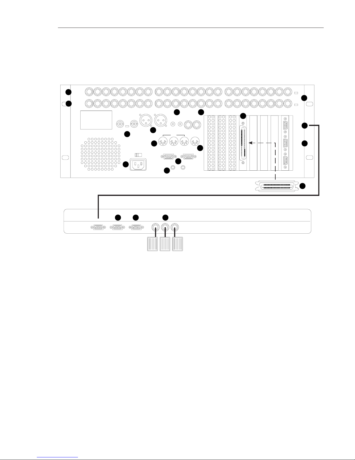
1.6 CONTROLS & INDICATORS
Please Note: This information is provided to familiarize you with your
RADAR. Complete installation instructions appear in Appendix A.
1.6.1 Rear Panel Connectors
[1] Audio Inputs
[2] Audio Outputs
[3] -10/+4 Level Settings
[4] Video Reference/Word Clock Input
[5] AES/EBU Digital I/O
[6] S/PDIF Digital I/O
[7] SMPTE Timecode In/Out(SMPTE output not currently active)
[8] MIDI Connections (not currently active)
[9] PC Keyboard Connection (not currently active)
[10] RADARLINK
[11] External Grounding
[12] AC Power Input Receptacle
[13] External SCSI Port
[14] RE-8 Connector
[15] External Machine Control (not currently active)
[16] SCSI Terminator: This must be installed here, or as the last item on the
SCSI “chain”.
[17] RE-8 Session Controller Connector
[18] Mouse Port (not currently active)
[19] Foot Switch Inputs
1
2
3
4
5
6 7
8
9
10
11
12
14
15
16
17 18 19
AUDIO
OUTPUTS
AUDIO
INPUTS
EXPANSION PORT
SYNC
REFERENCE
IN OUT OUTIN
AES/EBU
OUTIN
S/PDIF
OUTIN
LTC
SMPTE/EBU
MIDI PC KBD
OUTTHRU IN IN
RADARLINK CONTROL
OUTIN
CHS
GND
ANA
GND
ON OFF
75Ω
115 VAC
50/60 Hz
220\240VAC
50 Hz
115V
SCSI
OUT
IN
OUT
IN
LEVEL
OUT
LEVEL
IN
+4 -10
+4 -10
TO
REMOTE
SERIAL
IN
SERIAL
THRU
24 23 22 21 20 19 18 17 16 15 14 13 12 11 10 9 8 7 6 5 4 3 2 1
13
TO RADAR AUX MOUSE
FOOTSWITCH
INPUTS
123
WELCOME TO RADAR! 1-7
Edition 2 (Printed in Japan)
Page 24
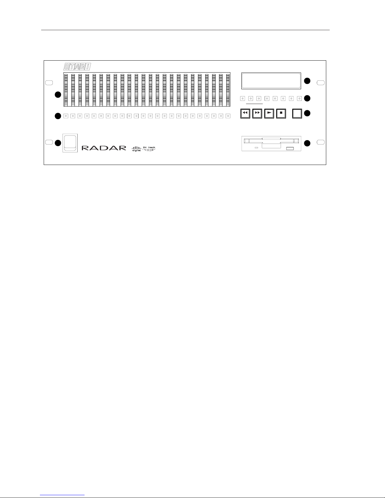
1.6.2 RADAR Front Panel Controls & Indicators
Refer to this diagram to navigate RADAR’s front panel:
[1] Meters and Input Level References: For more information see §3.3.
[2] Track Arming keys: For more information see §3.2.
[3] Power On/Off switch: For more information see §2.4.
[4] LCD: For more information see Section 4.
[5] Front Panel Function keys: Consult the Index in this manual for
individual descriptions.
[6] Transport keys: For more information see Section 3.
[7] Floppy Disk Drive: High density 3.5 inch floppy disk drive; software
upgrades will be received through this drive. (See Appendix A for further
information.)
IMPORTANT!
SYSTEM BOOT SOFTWARE IS ALREADY INSTALLED ON THE
RADAR HARD DRIVE; THEREFORE IT IS NOT NECESSARY TO PUT
THE SUPPLIED SYSTEM SOFTWARE DISKETTE IN THE DISK
DRIVE. DO, HOWEVER, KEEP THE SYSTEM DISKETTE HANDY
SHOULD IT BE NEEDED IN THE FUTURE.
2
1
3
4
5
6
7
CLIP
0
-3
-6
-10
-14
-18
-25
-35
-45
-55
1
CLIP
0
-3
-6
-10
-14
-18
-25
-35
-45
-55
CLIP
0
-3
-6
-10
-14
-18
-25
-35
-45
-55
CLIP
0
-3
-6
-10
-14
-18
-25
-35
-45
-55
CLIP
0
-3
-6
-10
-14
-18
-25
-35
-45
-55
CLIP
0
-3
-6
-10
-14
-18
-25
-35
-45
-55
23456789101112131415161718192021222324
AUTO
PLAY
00:00:00:00.00
LOC:04 CHORUS 01
HRS/BAR MIN/BEAT SEC/STEP FRM SUB
MENU/
CANCEL
UP/
YES
DOWN/NOMARK
LOC
AUTO
INPUT
RECALL
LOC
EXT
SYNC
VARI-
SPEED
2nd
FUNC
AUTO
PUNCH
CYCLE
EDIT
LOC
UNDO/
REDO
CURS L CURS R
REC
RANDOM ACCESS DIGITAL AUDIO RECORDER
Edition 2 (Printed in Japan)
1-8 SECTION 1
Page 25

1.7 IMPORTANT INITIAL INFORMATION
IMPORTANT NOTE #1:
Do not power up RADAR before checking that the AC power setting is correct
for your area! This is preset at the factory for the shipping destination but it may
still be incorrect. The switch is located at the lower left corner of the RADAR
by the fan outlet vent.
IMPORTANT NOTE #2:
Do not power up RADAR unless the SCSI terminator is connected correctly. If
you have no external backup device or hard drives connected, the terminator
must be plugged into the SCSI port on RADAR. If you do have external devices
connected, the terminator must be connected to the SCSI through port on the
last external device.
IMPORTANT NOTE #3:
Always power down RADAR through the menu. The Shutdown submenu is for
this purpose. Never power down while the LCD displays the Saving State
message. The Saving State function organizes the contents of RADAR’s RAM
(temporary memory) and writes it in more permanent form to the hard disks.
Saving State will occur only after recording or changing data, for example, after
Record, Edit, Edit Loc and Marking In and Out points. It has been timed to
occur five seconds after returning to Ready mode from these operations. (This
time is adjustable on the Preferences menu.)
IMPORTANT NOTE #4:
If you want to “wipe the disks clean” (because you backed everything up and
want to start with a fresh system, select “ERASE ALL DISKS” from the Project
menu.
DO NOT select INIT DISKS from the Diagnostics menu, since you will
erase the system software as well as the audio data! Use this function ONLY
under supervision of Otari Technical Support!
WELCOME TO RADAR! 1-9
Edition 2 (Printed in Japan)
Page 26

Page 27

Edition 2 (Printed in Japan)
This section includes the following subsections.
2.1 INTRODUCTION ............................................2-2
2.2 BEFORE STARTING—PLEASE READ THIS! ......................2-2
2.2.1 AC Power Level Setting..............................2-2
2.2.2 SCSI Terminator Installation...........................2-2
2.3 AUDIO INPUTS/OUTPUTS....................................2-3
2.3.1 About Audio Reference Levels ........................2-3
2.3.2 Audio Connections—Analog.........................2-3
2.3.3 Audio Connections—Digital..........................2-4
2.4 POWER ON/OFF PROCEDURE...............................2-5
2.4.1 Power Up Procedure ................................2-5
2.4.2 Power Down Procedure..............................2-5
2.5 ARMING TRACKS OVERVIEW ................................2-6
2.6 RECORDING & PLAYBACK OVERVIEW ........................2-6
2.7 LOCATING IN THE RECORDED AUDIO........................2-7
2.7.1 Locating Using Fast Wind Keys.......................2-7
2.7.2 Jog/Shuttle Operation (RE-8 Only) ....................2-7
2.7.2.1 Entering Jog Mode...............................2-7
2.7.2.2 Entering Shuttle Mode ............................2-8
2.8 DISK TIME AVAILABLE.........................................2-8
2.9 NAVIGATING RADAR’S MENU ...............................2-9
2.9.1 Menus Overview ...................................2-9
2.9.2 Moving Around in Menus............................2-9
2.9.2.1 Menu Operation Using the RE-8....................2-9
2.9.2.2 Front Panel Menu Operation.......................2-9
2.9.3 Navigating the Menu ..............................2-10
2.9.4 Menu Structure.....................................2-10
2.10 RADAR PROJECTS OVERVIEW ..............................2-11
2.10.1 Default Project....................................2-11
2.10.2 Creating a New Project...........................2-11
2.10.3 Switching Between Projects........................2-11
2.10.4 Naming Projects..................................2-12
2.10.5 Copying Projects .................................2-12
2.10.6 Project Start Time .................................2-12
2.10.7 Project Sample Rate...............................2-12
2.10.8 Deleting Projects..................................2-12
2.10.9 Reclaiming Disk Space from Deleted Project(s).......2-13
2.11 EDITING/AN OVERVIEW..................................2-14
2.10.1 Edit Markers (MARK IN, MARK OUT)...............2-14
2.10.2 RADAR’s Editing Clipboard ........................2-14
Section 2 Product Overview/Getting Started!
Page 28
2.1 GENERAL
This section provides information on how to get started quickly and trouble-free
on RADAR. This section divides into subsections which describe some helpful
RADAR features, and provides some basic operation.
For convenience, a brief installation overview is provided here; however
Appendix A provides complete system installation instructions.
2.2 BEFORE STARTING—PLEASE READ THIS!
In order to avoid inconveniencing yourself, and/or to avoid damaging the
system, follow a few precautions:
2.2.1 AC Power Level Setting
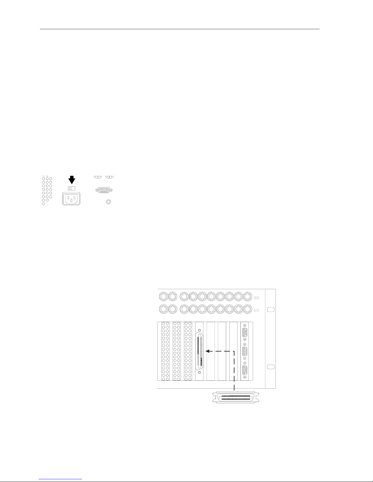
Please check the AC voltage setting on the back panel for the proper line voltage
for your area! If you set this incorrectly, poor system performance (and/or
smoke) may result!
If the voltage setting is incorrect, use a flat-blade screwdriver to change it.
2.2.2 SCSI Terminator Installation
Please check that the SCSI terminator is attached to the rear panel’s SCSI
connector!
CAUTION!
IF THE TERMINATOR IS NOT PROPERLY INSTALLED, POOR
SYSTEM PERFORMANCE WILL RESULT!
Please Note: If you have a backup device connected, make sure that the SCSI
terminator is attached to one of the SCSI connectors on the backup unit.
SCSI
OUT
IN
LEVEL
OUT
LEVEL
IN
+4 -10
+4 -10
TO
REMOTE
SERIAL
IN
SERIAL
THRU
109 87654321
OUTTHRU
IN
115 VAC
50/60 Hz
220\240VAC
50 Hz
115V
RADARLINK
Edition 2 (Printed in Japan)
2-2 SECTION 2
Page 29
2.3 AUDIO INPUTS/OUTPUTS
RADAR uses 1/4" phone plugs for audio input and output; these may be
balanced or unbalanced, +4 or -10 signal level. RADAR’s AES/EBU inputs and
outputs use one XLR cable per pair; the S/PDIF inputs and outputs use RCA
connectors.
2.3.1 About Audio Reference Levels
Zero dB in digital audio equipment is the maximum signal level that an input
device such as a mixer, effects unit or recording machine can accept to gain
optimum signal-to-noise ratio before distorting. When a VU meter shows an
input signal level of 0 VU, +4 gear will be actually 4 dB above .775 volts RMS.
When the meter shows 0 VU on -10 gear, the s signal is 10 dB below 1 volt
RMS. RADAR will adjust its meter sensitivity to your selection.
RADAR accepts either standard reference level; +4 and -10. These levels are set
using switches on the rear panel (see Step 3, below). Be sure to consult your
audio mixer’s manual if you are unsure of the proper level at which to set
RADAR.
Please Note: The input and output levels do not always have to be set to the
same settings. The input could be set to +4 dBu and the outputs could be at -10
dBV. This may be useful in the situation where a +4 dBu microphone preamp is
connected directly to one of RADAR’s inputs and you are using an -10 dBV
unbalanced mixing console.
2.3.2 Audio Connections—Analog
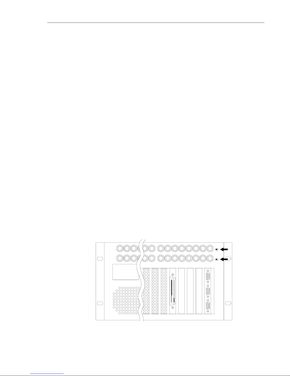
1. Connect source audio to the audio inputs (on the lower row).
2. Connect a console (or other monitoring system) to the corresponding
outputs (top row of RADAR connectors).
3. Set the LEVEL IN and LEVEL OUT switches to the correct level (i.e.,
+4 or -10). Please note that these switches may be set differently!
AUDIO
OUTPUTS
AUDIO
INPUTS
EXPANSION PORT
SCSI
OUT
IN
LEVEL
OUT
LEVEL
IN
+4 -10
+4 -10
TO
REMOTE
SERIAL
IN
SERIAL
THRU
24 23 22 21 10 9 8 7 6 5 4 3 2 1
PRODUCT OVERVIEW/GETTING STARTED! 2-3
Edition 2 (Printed in Japan)
Page 30
2.3.3 Audio Connections—Digital
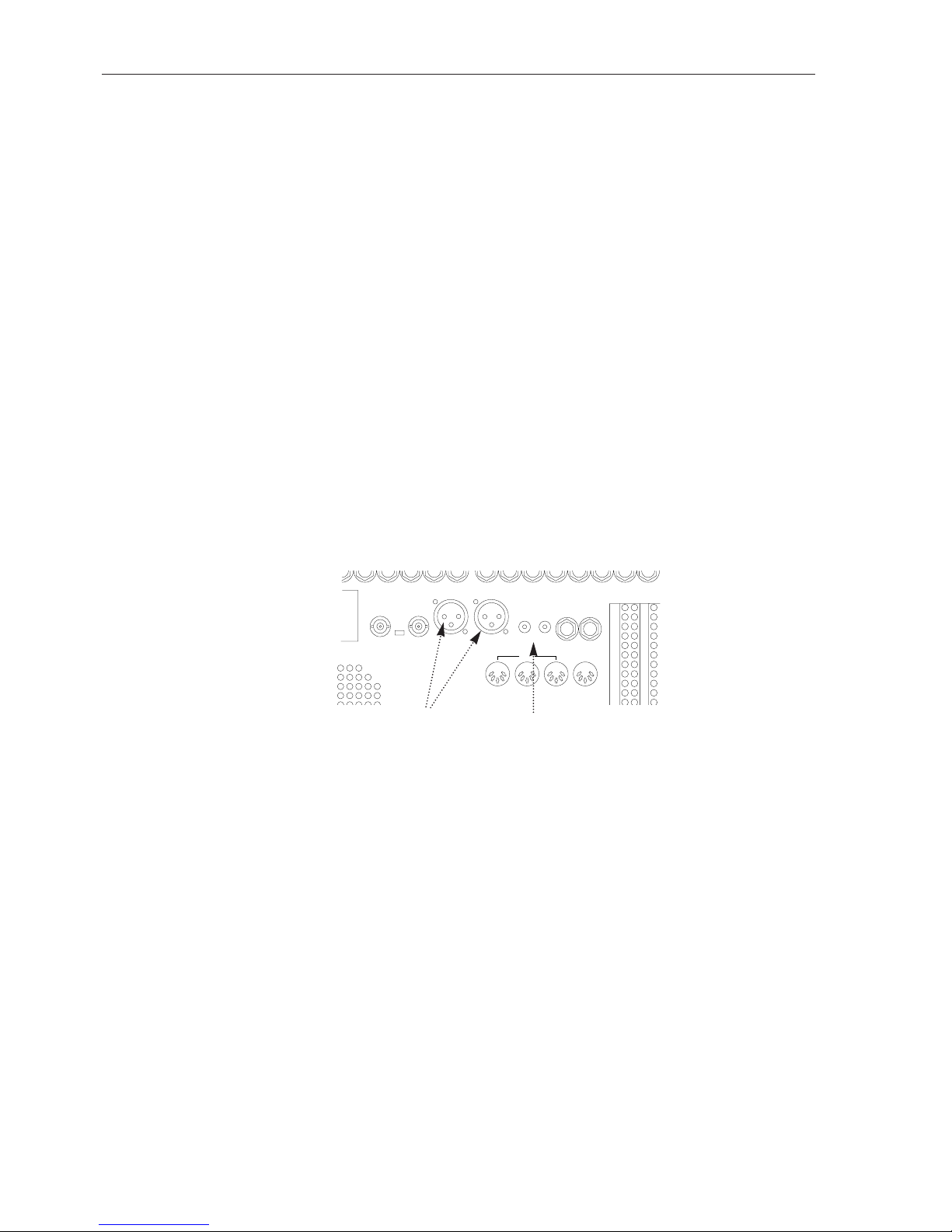
RADAR provides both AES/EBU (professional) and S/PDIF (consumer) digital
audio interfaces. AES/EBU uses one balanced, XLR cable per pair; S/PDIF uses
one unbalanced RCA cable per pair.
RADAR can record stereo digitally on any two track pairs, and can output
digitally from any two adjacent track pairs (that share the same disk drive).
Complete instructions for this feature appear in §3.17.
Please Note: Be sure to use the highest-quality shielded cables and best quality
connectors for any digital audio application!
If using AES/EBU:
1. Connect an AES/EBU source to RADAR’s AES/EBU IN XLR (female
XLR connector), as shown below.
2. Connect RADAR’s AES/EBU OUT XLR to the desired device using a
properly shielded cable and a female XLR cable connector, as shown.
If using S/PDIF:
1. Connect an S/PDIF source to RADAR’s S/PDIF IN (female RCA jack),
as shown below.
2. Connect RADAR’s S/PDIF OUT to the desired device using a properly
shielded cable and a male RCA cable connector, as shown.
SYNC
REFERENCE
IN OUT OUTIN
AES/EBU
OUTIN
S/PDIF
OUTIN
LTC
SMPTE/EBU
MIDI PC KBD
OUTTHRU IN IN
RADARLINK CONTROL
ON OFF
75Ω
Edition 2 (Printed in Japan)
2-4 SECTION 2
Connect S/PDIF
input & output here,
using RCA male
connectors
Connect AES/EBU
input & output here
using XLR (balanced!)
cables & connectors
Page 31

2.4 POWER ON/OFF PROCEDURE
2.4.1 Power Up Procedure
Please Note: Turn the backup device’s power on before turning on RADAR.
Press the power switch located on the left side of the front panel of RADAR
to the On position. RADAR will take a few moments to go through its power-
up routine, and the LCD will display the following patterns:
RADAR
DIGITAL 24 TRACK
↓
DRIVES FOUND: 3
TESTING SCSI: 6
↓
Booting From
Floppy....
↓
Booting From
SCSI 0: »
↓
00:00:00:00.00
* MOUNTING *
And finally...
00:00:00:00.00
LOC:01
This display means that RADAR is ready for operation. The LCD shows the
current SMPTE location, and current location point.
2.4.2 Power off Procedure
IMPORTANT: DO NOT SWITCH OFF BEFORE MENU SHUTDOWN.
Before pressing the power switch to power down, you must have RADAR save
system data to the hard disks.
1. Press MENU/PREV (on RE-8) or MENU/CANCEL (on front panel).
The system will display the Main menu.
2. Use the DOWN key to scroll to the last submenu, or simply turn the
jog wheel to the right until the following item appears in the LCD:
MAIN MENU:
SHUTDOWN RADAR
3. Press ENTER. RADAR will ask you to confirm the shutdown.
SYSTEM SHUTDOWN
PROCEED? N
O
4. Use the cursor up/down keys to change between NO and YES (or turn
the jog wheel to make the selection). Press ENTER. The LCD will
indicate it is saving the current system state, then confirm a safe shutdown:
YOU MAY SAFELY
TURN OFF POWER
5. Turn the power switch Off.
Please Note: After a shutdown, RADAR cannot be operated again until the
power has been switched off then on!
PRODUCT OVERVIEW/GETTING STARTED! 2-5
Edition 2 (Printed in Japan)
Page 32
Edition 2 (Printed in Japan)
2-6 SECTION 2
2.5 ARMING TRACKS OVERVIEW
Both the front panel and the RE-8 have track arming keys for all tracks—when
tracks are armed, the key(s) show red flashing lights.
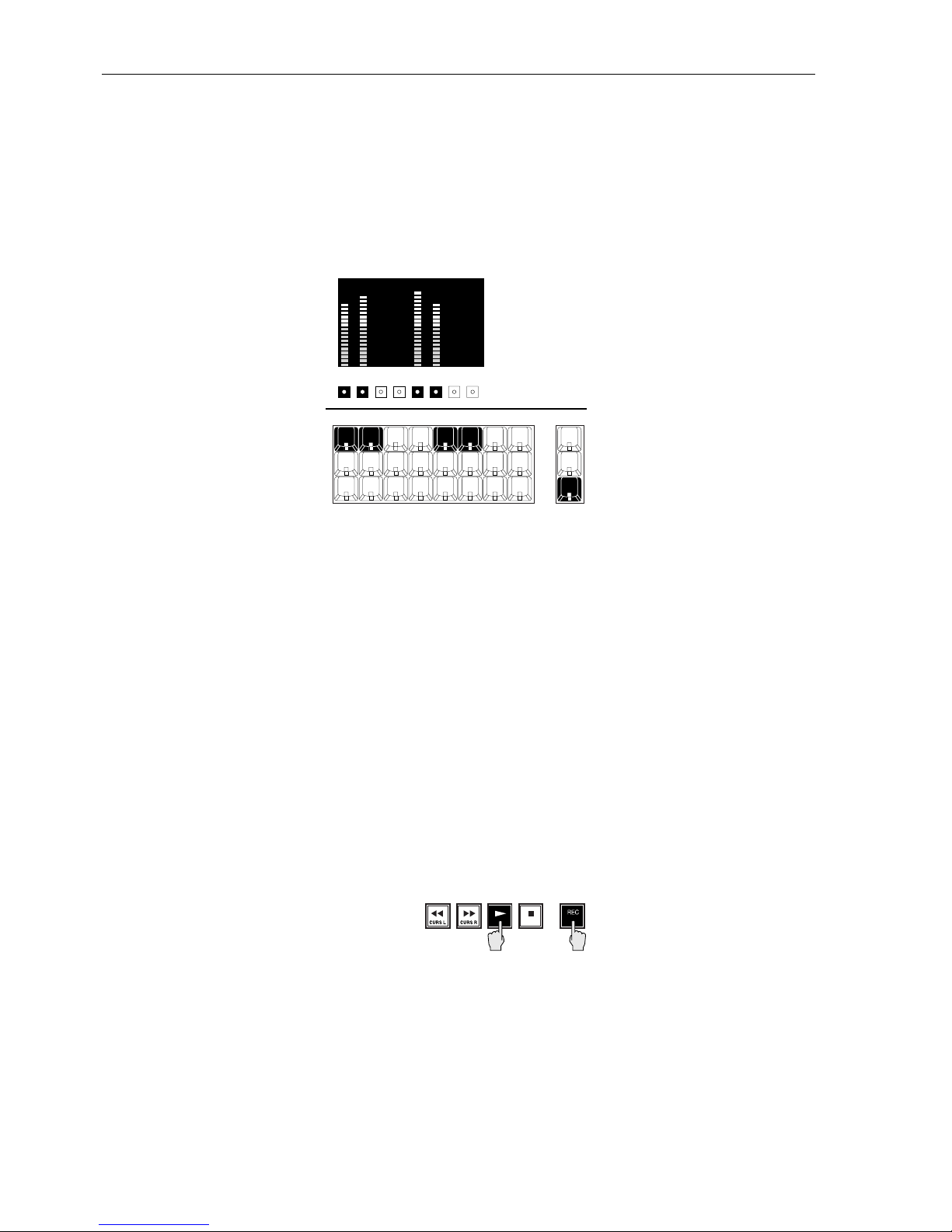
1. Arm the track(s) you want to record on using the track arm keys on the
front panel, or on the RE-8.
2. Cue and start the audio source. You will see input levels on the front
panel level meters:
3. While watching the levels display(s) on the front panel, set the audio
input levels to a safe (i.e. non-clipping) level using the console, etc.
IMPORTANT NOTE: The maximum recording level allowable before digital
clip is +22 dBu. This level corresponds to 0 dB on RADAR’s meter display.
Clip Indicator LEDs: The red clip LED located at the top of each individual
meter indicates that the input signal has clipped. More information about the
clip indicators appears in §3.3.2.
2.6 RECORDING & PLAYBACK OVERVIEW
Recording and playback use the transport keys on either the front panel or the
RE-8 session controller.
1. To enter record, press/hold PLAY then press REC, or...
press/hold REC and press PLAY.
2. Press PLAY to drop out of record with the transport still rolling, or
press STOP to stop both recording and the transport as well.
3. To enter PLAY at any time, simply press PLAY.
Please Note: Two methods of entering Record are provided—the traditional
two-key method described here, or the REC key only. The desired method may
be selected on the Preferences menu, described in §4.3.4.5.
RADAR
Front Panel
RE-8
CLIP
0
-3
-6
-10
-14
-18
-25
-35
-45
-55
CLIP
0
-3
-6
-10
-14
-18
-25
-35
-45
-55
12345678
12345678
910111213141516
17 18 19 20 21 22 23 24
REC
SAFE
TRACK
SOLO
AUTO
INPUT
Page 33
2.7 LOCATING IN THE RECORDED AUDIO
RADAR provides a number of methods for locating the transport—you may
use the transport controls or Jog/Shuttle features, you may enter the desired
time and locate there, or you may set and recall autolocate points.
Please Note: Instructions on RADAR’s autolocator and direct time entry
features are provided in §3.12.
2.7.1 Locating Using Fast Wind Keys
You may use the fast-wind keys to locate forward or backwards in the audio.
Please Note: Press the key once to fast-wind at six times play speed. Or, double-
press the key to fast-wind at eighteen times play speed. (Other speed settings for
fast-wind may be specified on the Preferences menu, described in §4.3.4.)
Cue to Audio: You may use RECALL LOC plus the fast wind keys to skip to
the beginning or end of a slient section. This feature is described in §3.12.1.2.
2.7.2 JOG/Shuttle Operation (RE-8 only)
RADAR’s Jog/Shuttle modes provide fast, precise location in recorded material.
Shuttle mode uses the jog wheel to vary the speed and direction of audio for
locating points; Jog mode allows you to “scrub” the audio to find exact locations.
Please Note: The jog wheel may also be used as a convenient control device
when scrolling through RADAR’s menus. When used as an input device,
turning the wheel to the right increases the value on screen, and turning it to
the left decreases the value.
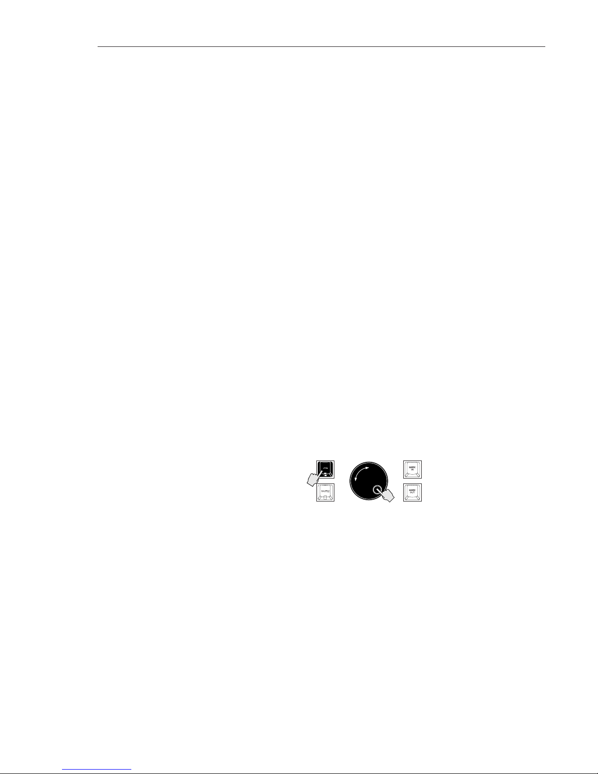
2.7.2.1 Entering Jog Mode
Press the JOG key to the left of the wheel to engage Jog mode:
Turning the wheel clockwise or counterclockwise produces variable speed
playback for as long as you continue turning it. When you stop turning the
wheel, playback will stop. The speed of playback varies from scrub where you
can accurately locate the first transient of an audio waveform by rocking the
wheel gently forward and backward to slightly above normal playback speed.
Jog “Bump”: You may “bump” the current location while in Scrub by pressing
the cursor left or right keys. Each cursor press will nudge the jog location by the
smallest possible wheel increment.
To exit Jog mode, press any key (including JOG).
1
2
PRODUCT OVERVIEW/GETTING STARTED! 2-7
Edition 2 (Printed in Japan)
Page 34
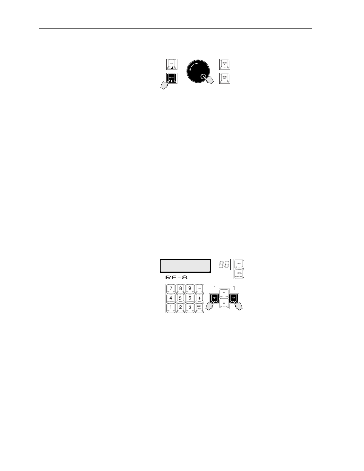
2.7.2.2 Entering Shuttle Mode
Press SHUTTLE (located below JOG) at any time to engage Shuttle mode:
Shuttle produces playback at variable speeds like Jog with one difference; when
you stop turning the wheel, playback continues at the current speed until you
move the wheel again or press a transport key.
To exit Shuttle mode, press any key including SHUTTLE.
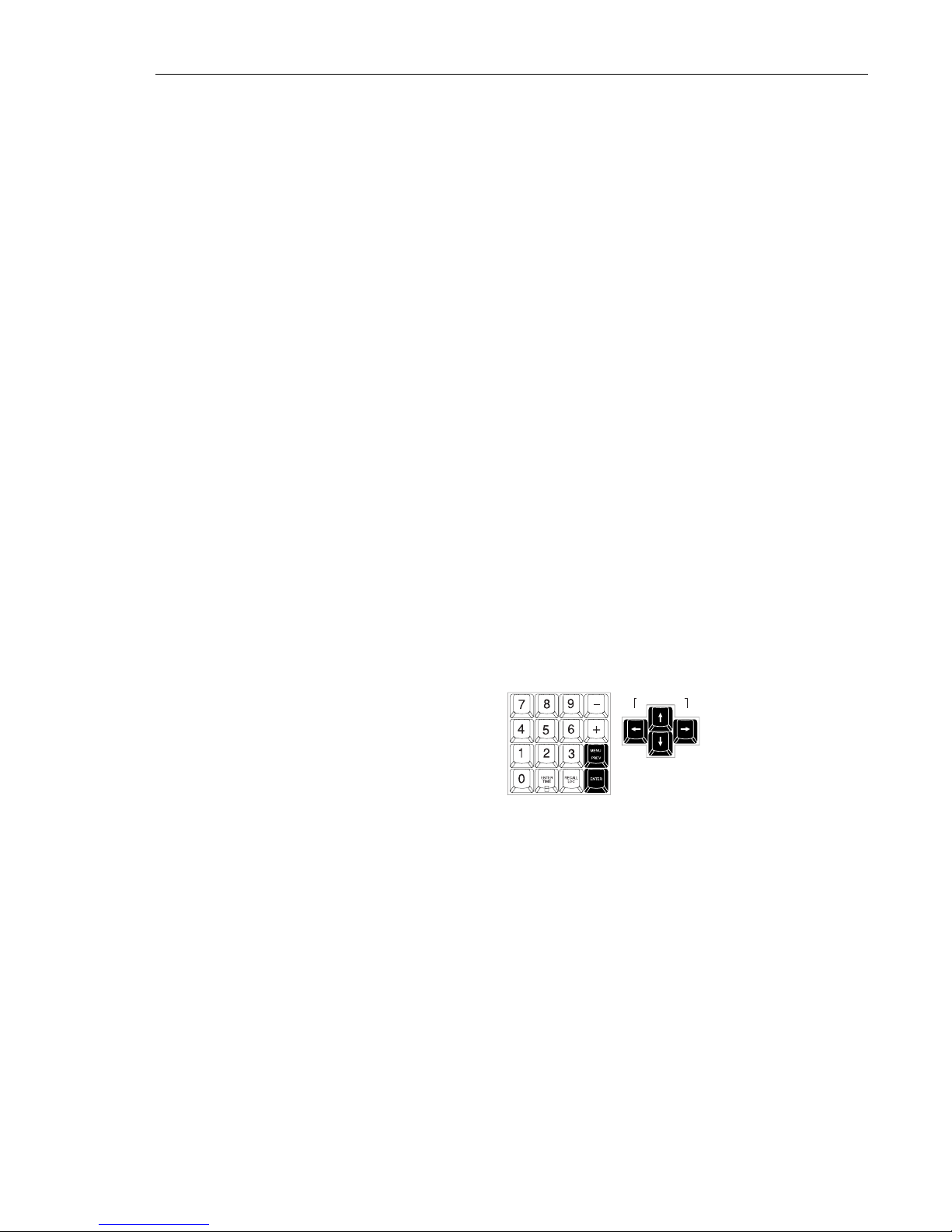
2.8 DISK TIME AVAILABLE
To check the amount of disk time available to you, press/hold the RE-8’s cursor
left and right arrows. The display will show the amount of free time on each of
the system’s hard disks.
The display is in ACTUAL recording minutes available—if you have 20
minutes of track time available on Disk 1, and no tracks armed, it shows 20
minutes. If, however, you have two tracks armed for recording, it will show 10
minutes (i.e. 10 minutes per track x 2 tracks = 20 minutes).
Please Note: If tracks are armed for a particular disk, the time left number for
that disk will flash on and off.
Please Note: Disk Time Available is also available as an item on the System
Menu (§4.3.1).
RECORD TIME LEFT
A012 B023 C004
HRS/BAR MIN/BEAT SEC/STEP FRM SUB
DISK SPACE REMAINING
REMOTE EDITING CONTROLLER
2
1
Edition 2 (Printed in Japan)
2-8 SECTION 2
Page 35
2.9 NAVIGATING RADAR’S MENUS
2.9.1 Menus Overview
RADAR provides a set of menus on the LCD for access to features that are used less
often and do not require a dedicated key. The menu system consists of layers of
topics ranging from general categories (five) to more specific functions; many of
these end in what we call a “dialog ”, which is a menu that needs your input.
When you press the MENU key on the RE-8 or the MENU/CANCEL key on
the front panel, the LCD screen presents you with a Main menu, which
includes the most general listing of topics:
SYSTEM MENU
PROJECT MENU
EDIT MENU
PREFERENCES MENU
DIAGNOSTIC MENU
SHUTDOWN RADAR
From these choices, you select more specific items called submenus. From a
submenu, you will be presented with an editing dialog or an additional submenu.
2.9.2 Moving Around in Menus
Menu navigation is slightly different between the front panel or RE-8 session
controller.
2.9.2.1 Menu Operation using the RE-8
The MENU/PREV and ENTER keys, plus the cursor keys, are used to enter/exit
the menu and to travel up and down through the menu system, as shown. The jog
wheel may be used to scroll quickly through menus—and when a menu item is
selected requiring input, the jog wheel may be used to “dial in” a value.
2.9.2.2 Front Panel Menu Operation
The row of keys beneath the front panel’s LCD enable you to enter/exit the
menu and to travel up and down through the menu system. However, to
conserve key usage, the FFWD, RWD and STOP keys perform alternate
functions while in Menu mode. (These keys are printed with two legends
indicating their menu functions.)
RWD doubles as the cursor left control.This is for cycling backward through
options shown in the LCD prompt.
FFWD doubles as the cursor right control. This is for cycling forward
through options shown in the LCD prompt.
STOP doubles as the ENTER key. You may use the STOP/ENTER key to
accept a choice offered in the LCD prompt.
DISK SPACE REMAINING
PRODUCT OVERVIEW/GETTING STARTED! 2-9
Edition 2 (Printed in Japan)
Page 36

2.9.3 Navigating the Menu
From the RE-8: Press MENU/PREV to enter the menu. (Press again or press
CANCEL to exit.)
Please Note: You may enter the menu while playing or recording without
interrupting either mode. Transport controls are inactive until you exit Menu
mode.
Pressing MENU/PREV any time you are within the menu will cancel the last
entry and present the previous (higher-level) menu. You can continue pressing
MENU/PREV to cycle backward through the submenus and exit to Ready
mode, or... you may press CANCEL at any time to leave the Menu and any
other dialog screen right away. To select an item (or a submenu), press ENTER.
From the Front Panel: Press and release the MENU/CANCEL key to enter the
menu. (There is no PREV function as on the RE-8.) You may only CANCEL
back to Ready mode. Use the front panel keys to move through the menus; you
may also use the UP/YES and DOWN/NO keys to enter numeric values.
2.9.4 Menu Structure
The Main menu is available, from the RE-8, by pressing the MENU/PREV key.
Or, you may press the MENU/CANCEL key on the front panel.
Use the UP and DOWN keys (front panel) or the jog wheel (RE-8) to scroll
through these listings.
Please Note: For a detailed description of all RADAR menu items, please refer
to Section 4.
Edition 2 (Printed in Japan)
2-10 SECTION 2
SYSTEM MENU SYSTEM VERSION
SHOW DISK SPACE
DIGITAL I/O
SYNC OUTPUT
CONFIGURE DISKS
SET TIME & DATE
UPGRADE SYSTEM
PROJECT MENU BACKUP MENU
RESTORE MENU
GOTO PROJECT
CREATE PROJECT
NAME PROJECT
COPY PROJECT
DELETE PROJECT
SAMPLE RATE
START TIME
SYNC OFFSET
RECLAIM SPACE
RENUMBER LOCATES
ERASE ALL DISKS
EDIT MENU UNDO/REDO
MODIFY EDIT
CUT
COPY
PASTE
MOVE
ERASE
LOOP
SLIDE
REVERSE
LISTEN
IMPORT *.WAV
CROSSFADE TIME
RECORD SAFE
PREFERENCES MENU DEFAULT SMPTE
FIELD
TRACK SOLO MODE
LOW DISK
WARNING
SLIDE TIME
UNITS
RECORD MODE
FFWD & REW RATE
PEAK HOLD TIME
CLIP HOLD TIME
SAVE STATE
DELAY
DIAGNOSTICS MENU SCAN SCSI BUS
MOUNT / UNMOUNT
INIT DISK
CHECK DISK
REPAIR DISK
SHOW FREE RAM
CONFIGURE DEBUG
SHOW DEBUG
SAVE DEBUG
PLAYLIST ERRORS
REALTIME ERRORS
SHUTDOWN RADAR
Page 37

2.10 RADAR PROJECTS OPERATION
In many ways, RADAR behaves exactly like a reel-to-reel tape machine.
However, RADAR provides many important features that are only possible
because of the random-access nature of hard disk digital recording.
RADAR supports up to 99 different projects, each of which is a playlist that has
its own recorded material, locate points, sampling rate, sync offset, and start
time.
With multiple projects, you may create, say, a Project 01 that starts at SMPTE
timecode of one hour; you may then create a new Project 02, that has
completely different recorded material, but also starts at SMPTE timecode of
one hour!
Another advantage of multiple projects is when editing—you may edit Project
02 as needed, without changing Project 01 in any way; you may record new
material into a project without overwriting material in any other project. (The
only limitation is the amount of recording time remaining, which is shared among
all projects.)
A third advantage of RADAR’s project architecture is that you may copy
material between projects using the editing clipboard, and you may also copy
entire projects! Thus, you may record raw material into Project 01, then copy
’01 to ’03. You can then edit Project 03 as desired—but the original Project 01 is
always available in its un-edited form!
Please Note: Because projects are simply “playlists”, copying material between
projects does NOT reduce the amount of free recording time.
2.10.1 Default Project
When RADAR boots on a “clean” system, it automatically creates and loads an
empty project 01... you may use this project as desired (or all the time—since
you are not forced to use the multiple-projects feature if you don’t need to!).
Please Note: RADAR remembers the last active project number on shutdown,
and re-loads it on power-up.
2.10.2 Creating a New Project
When you want to create a new project, select CREATE PROJECT from the
Project menu. You may then enter a name for the new project—RADAR assigns
the first available project number, which then appears on the 2-digit LED of the
RE-8.
2.10.3 Switching Between Projects
To change the current project, select GOTO PROJECT from the Project menu.
The system will display the current on the system; use the UP and DOWN
keys, the cursor arrows, or the jog wheel to display the desired project, then
press ENTER to select it.
PRODUCT OVERVIEW/GETTING STARTED! 2-11
Edition 2 (Printed in Japan)
Page 38

2.10.4 Naming Projects
To name a project:
1. Select NAME PROJECT from the Project menu.
2. Use the up/down arrows (or the jog wheel) to select the project to
rename, then use the RE-8 QWERTY keyboard to enter the name.
Please Note: On the front panel, use the cursor left/right keys to move on the
LCD. Use the UP and DOWN keys to select letters. Press/hold UP or DOWN
to scroll quickly through the available characters.
Each project may be named with up to 13 characters. (The system allows you to
enter a 16-character name, but the last three characters may be erased if the
project is ever copied.) If a project is never explicitly named, it uses the name
“UNTITLED”.
2.10.5 Copying Projects
To copy a project:
1. Change to the project to be copied. (If not there already.)
2. Select COPY PROJECT from the Project menu. RADAR will then copy
the current project to the first unused Project location, append the project
name with the suffix “V 2”, then change to that project. (If you copy the
project from V 2, the suffix changes to V 3, etc.)
2.10.6 Project Start Time
Each project may have a user-definable “start time”, which is simply a reference
marker, since recording over the entire 24-hour span is available. When
switching to a project, the system automatically locates to the start time; this
time is also available in the project as location point 0.
The default start time for projects is 00:00:00:00.00; to enter a different start
time, select START TIME from the Project menu, then enter the desired time.
2.10.7 Project Sample Rate
Like start times, different projects may have different sample rates. To change
the sample rate, first switch to the project (if not already active), then select
SAMPLE RATE from the Project menu. Use the UP/DOWN keys or the jog
wheel to select the desired sample rate, then press ENTER.
2.10.8 Deleting Projects
If you are finished with a project and want to remove it from the system, first
change to the project to be deleted (if not there already). Select DELETE
PROJECT from the Project menu. The system will ask for a confirmation, then
the project playlist will be deleted, and the project number marked as unused.
Please Note: Audio used by a deleted project is NOT deleted until a “reclaim
space” operation is performed (see below).
Edition 2 (Printed in Japan)
2-12 SECTION 2
Page 39

2.10.9 Reclaiming Disk Space from Deleted Projects
Since multiple projects can reference the same audio, when deleting a project, its
playlist information (and locate points) are deleted, but the audio is NOT
deleted. Also, as edits are performed, small amounts of disk space are used for
crossfades, etc. This audio may not be released after a cut or erase operation; the
Reclaim Space feature will release the space.
The “reclaim space” feature processes all projects on the system to determine
what audio is not being referenced by any project. Once finished with the
processing, RADAR erases the unused audio data, reclaiming the space for
future use.
IMPORTANT:
Audio deleted using Reclaim Space is NOT recoverable! Also, the process may
take up to five minutes to complete, depending on the number of projects on
the system.
To use Reclaim Space, select this item from the Projects menu, then press
ENTER. We recommend you perform this operation occasionally, to free up unused
disk space on your system.
PRODUCT OVERVIEW/GETTING STARTED! 2-13
Edition 2 (Printed in Japan)
Page 40
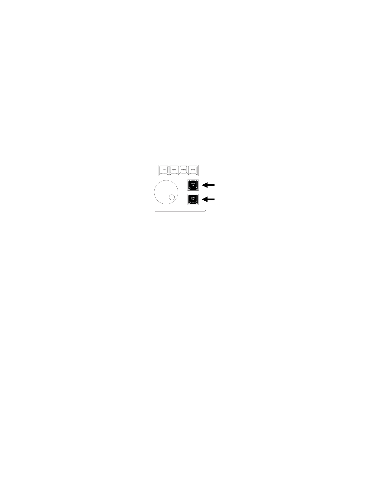
2.11 EDITING—AN OVERVIEW
RADAR provides all the editing features possible with tape and a razor blade,
plus many more. Like a tape machine, you may mark and cut across all tracks;
unlike a tape machine, you may cut on one track (or across any combination of
tracks).
2.11.1 Edit Markers (MARK IN, MARK OUT)
In tape editing, the operator rocks reels to find edit points, then uses a grease
pencil to mark them. Finally, edits are performed using a razor, at the marked
edit points.
In RADAR editing, you rock reels to find edit points (or mark points on the fly,
or set specific time code locations). Then, instead of the grease pencil, you set
special mark points called Mark In and Mark Out. You may set these using the
dedicated keys on the RE-8, as shown.
Please Note: From the front panel, you may set Mark In and Mark Out points
by pressing MARK LOC plus UP/YES (for a MarkIn at the current timecode
location), or MARK LOC plus UP/DOWN (for a MarkOut at the current
timecode location).
Once the Mark In and Mark Out points are set, the edit is performed using
dedicated edit function keys or RADAR’s Edit menu. The only additional steps
in RADAR editing beyond those in tape are in selecting which track(s) you
want to edit—these are selected using the track arm keys.
2.11.2 RADAR’s Editing Clipboard
In tape editing, after you cut a piece for use elsewhere, you might hang it over
your shoulder if it is short, or wind it onto an edit reel if it is longer. RADAR
uses a “clipboard” for storing cut or copied pieces. Once audio is on the
clipboard, it may be auditioned for content, and used elsewhere as needed.
Edition 2 (Printed in Japan)
2-14 SECTION 2
Page 41

Edition 2 (Printed in Japan)
This section describes RADAR’s transport features, and the extensive control
menus used for recording and editing, including installation and basic
operations.
This section includes the following subsections.
3.1 GENERAL
...................................................3-3
3.2 ARMING TRACKS FOR RECORD ..............................3-3
3.3 INPUT MONITORING/METERS DISPLAY.......................3-4
3.3.1 Peak Hold Indicators ................................3-4
3.3.2 Clip Indicator LEDs..................................3-4
3.4 SAMPLE RATE SELECTION ....................................3-5
3.4.1 Sampling Rate Overview ............................3-5
3.4.2 Changing RADAR’s Sample Rate......................3-5
3.5 RECORDING OPERATION....................................3-6
3.5.1 Entering Record.....................................3-6
3.5.2 Punching In on Additional Tracks .....................3-6
3.5.3 Punch Out (Dropping Out of Record)..................3-6
3.5.4 Record Safe Feature.................................3-8
3.5.5 Clear Rec-Ready (RE-8 Only) .........................3-8
3.5.6 Recording to Timecode ..............................3-8
3.6 PLAYBACK OPERATION ......................................3-8
3.6.1 Standard Playback..................................3-8
3.6.2 Reverse Playback ...................................3-8
3.6.3 Playback Locked to Timecode ........................3-8
3.7 TRACK SOLO FEATURE (RE-8 Only) ............................3-9
3.7.1 Additive Solo Mode Operation.......................3-9
3.7.2 Interlock Solo Mode Operation.......................3-9
3.7.3 Momentary Solo Mode Operation....................3-9
3.8 VARISPEED RECORDING/PLAYBACK .........................3-10
3.8.1 Varispeed Overview................................3-10
3.8.2 Changing Pitch with Varispeed ......................3-10
3.8.3 Changing Varispeed Units ..........................3-10
3.9 AUTO INPUT MODE ........................................3-11
3.9.1 Auto Input Overview ...............................3-11
3.9.2 Turning Auto Input On & Off ........................3-11
3.10 AUTO PUNCH MODE.....................................3-12
3.10.1 Setting Up for an Auto Punch ......................3-12
3.10.2 Editing Auto Punch In and Out Locations ............3-13
3.11 UNDO/REDO FUNCTIONS ...............................3-13
Section 3 Recording & Transport Operation
Page 42

SECTION 3—CONTENTS, CONTINUED
3.12 LOCATING IN THE RECORDED MATERIAL...................3-14
3.12.1 Cueing with Fast-Forward and Rewind..............3-14
3.12.2 Jog/Shuttle Mode (RE-8 Only) .....................3-14
3.13 AUTO LOCATION .........................................3-16
3.13.1 Programming a New Auto Locate Point .............3-16
3.13.2 Recalling Marked Locate Points from the Front Panel. . 3-16
3.13.3 Recalling a Locate Point from the RE-8 ..............3-16
3.13.4 Auto Play After Locate.............................3-17
3.13.5 Editing a Locate, Mark In, or Mark Out Point........3-18
3.13.6 Naming Locate Points from the Front Panel ..........3-19
3.14 LOCATING VIA DIRECT TIME ENTRY (RE-8 Only) .............3-20
3.15 CYCLE....................................................3-21
3.16 PRE/POST ROLL ...........................................3-22
3.17 DIGITAL I/O OPERATION ..................................3-23
Edition 2 (Printed in Japan)
3-2 SECTION 3
Page 43
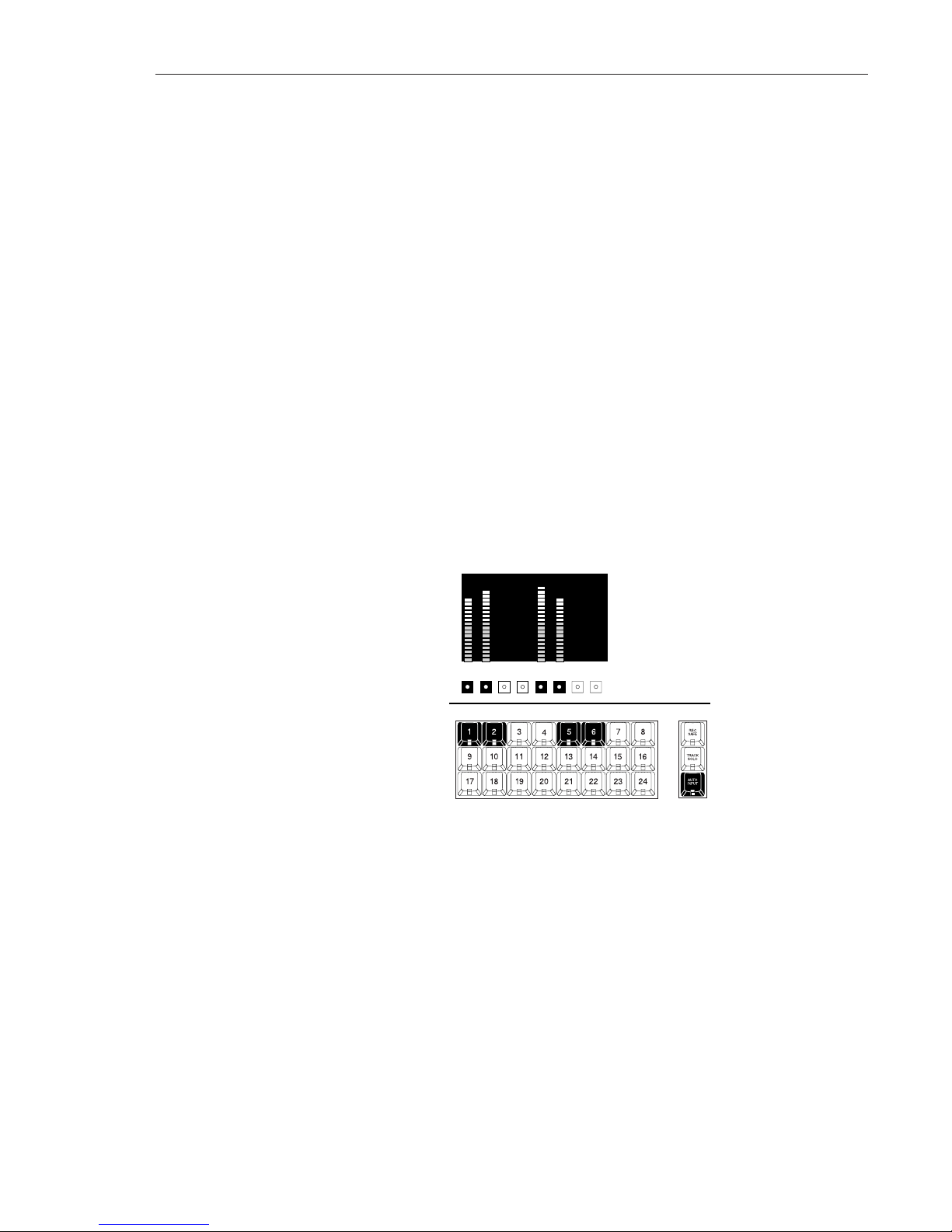
3.1 GENERAL
RADAR is designed with the best features of tape machines in mind—
particularly its simplicity of operation. This will allow you to learn the operation
of RADAR quickly and be productive with a minimum of down time.
This section describes recording and transport operation, including arming
tracks, input monitoring, recording, playback monitoring, and all transport
locate features including shuttle/jog and autolocation.
3.2 ARMING TRACKS FOR RECORD
There are 24 keys on the front panel of RADAR (and the RE-8) used to place
tracks in Record Ready mode. (These are referred to in this manual as Track Arm
keys.) The keys are momentary type with an LED in the center to indicate
Record Ready status, and when tracks are armed, the key(s) show red flashing
lights. Tracks may be armed in all transport modes including Record mode.
Press any armed track’s key again to disarm, and its LED will go out.
1. Arm the track(s) you want to record on using the track arm keys on the
front panel, or on the RE-8, then cue and start the audio source. You
will see input levels on the front panel level meters:
2. While watching the levels display(s) on the front panel, set the audio
input levels to a safe (i.e. non-clipping) level using the console, etc.
Please Note: If your audio source is producing insufficient levels for recording,
you may need to re-set the LEVEL IN/OUT switches on the rear panel. These
switches are described in §2.5.
IMPORTANT NOTE: The maximum recording level allowable before
digital clip is +22 dBu. This level corresponds to 0 dB on RADAR’s meter
display.
RADAR
Front Panel
RE-8
CLIP
0
-3
-6
-10
-14
-18
-25
-35
-45
-55
CLIP
0
-3
-6
-10
-14
-18
-25
-35
-45
-55
12345678
RECORDING & TRANSPORT OPERATION 3-3
Edition 2 (Printed in Japan)
Page 44

3.3 MONITORING/METERS DISPLAY
RADAR’s 24 meters provide instant and highly accurate input level indication.
Each individual meter has 20 LED parts: 10 green and 10 yellow. The LEDs are
calibrated to display a logarithmic scale from 0 dB down to -55 dB.
3.3.1 Peak Hold Feature
RADAR uses peak program ballistics with peak hold for input and output
metering. This type of metering most accurately allows you to assess transient
peaks that could overload RADAR and cause distortion. The top LED will
register a peak and will hold it momentarily before falling more slowly than the
other LEDs. In a dynamic section, the top LED will show an average of the
peaks it encounters.
Please Note: The peak hold duration may be set on the Preferences menu,
described in §4.3.4.7.
3.3.2 Clip Indicator LEDs
The red clip LED located at the top of each individual meter indicates that the
input signal has clipped. If clipping occurs, this LED will glow brightly for a
moment and then remain dim. The activity of the clip indicator LEDs may be
set on the User Preferences menu, described in §4.3.4.8.
Please Note: If a clip occurs, once you have reset the input level and no longer
need to see the clip LED, press the track arm key associated with the clipped
track off and then back on.
Edition 2 (Printed in Japan)
3-4 SECTION 3
Page 45

3.4 SAMPLE RATE SELECTION
3.4.1 Sampling Rate Overview
The number of times every second that a snapshot of the input audio signal is
taken is referred to as the sampling rate. RADAR supports all currently used
sampling rates: 32 kHz, 44.056 kHz, 44.100 kHz, 47.952 kHz, and 48 kHz.
The most important fact to consider before recording is that if you ever want to
transfer tracks between RADAR and another machine digitally, their sampling
rates must be the same. For instance, if you have a stereo rhythm track recorded
on DAT at 48 kHz sampling rate and you want to transfer it to RADAR to
build up a piece of music, RADAR’s sampling rate must match that of the DAT
recording at 48 kHz. If the sampling rates were set differently, the resulting
playback on RADAR would be altered in pitch.
Below is a chart showing some applications of various sample rates.
Sample Rate Minutes of Recording General Applications
(kHz) Time/Gigabyte (approx)
32 260 Digital sporken word recordings
44.056 189 Film & Video digital transfers
44.100 188 CD mastering
47.952 175 Video digital transfer
48 173 Digital transfer from DAT
3.4.2 Changing RADAR’s Sample Rate
1. Press MENU/PREV (RE-8) or MENU/ESC (front panel).
2. Scroll UP/DOWN through the choices until the PROJECT menu item
is displayed:
MAIN MENU:
P
ROJECT MENU
3. Press ENTER (RE-8) or STOP/ENTER (front panel).
4. Scroll through the submenus until the SAMPLE RATE item is
displayed:
MAIN/PROJ MENU:
S
AMPLE RATE
5. Press ENTER. The system will respond with:
SAMPLE RATE:
48 KHz
6. Use the cursor up/down keys (or the jog wheel) to select the desired
Sample Rate for the project. The available rates are 32, 44.1, 44.056,
47.952, and 48 kHz.
7. When you have selected the desired sample rate, press ENTER. This will
automatically accept the selection and escape from the menu.
Please Note: Sample rate setting is retained by the current project, and will be
recalled on the next power up. Other projects may have different sample rates;
however once a project has been created, its sample rate is retained.
RECORDING & TRANSPORT OPERATION 3-5
Edition 2 (Printed in Japan)
Page 46
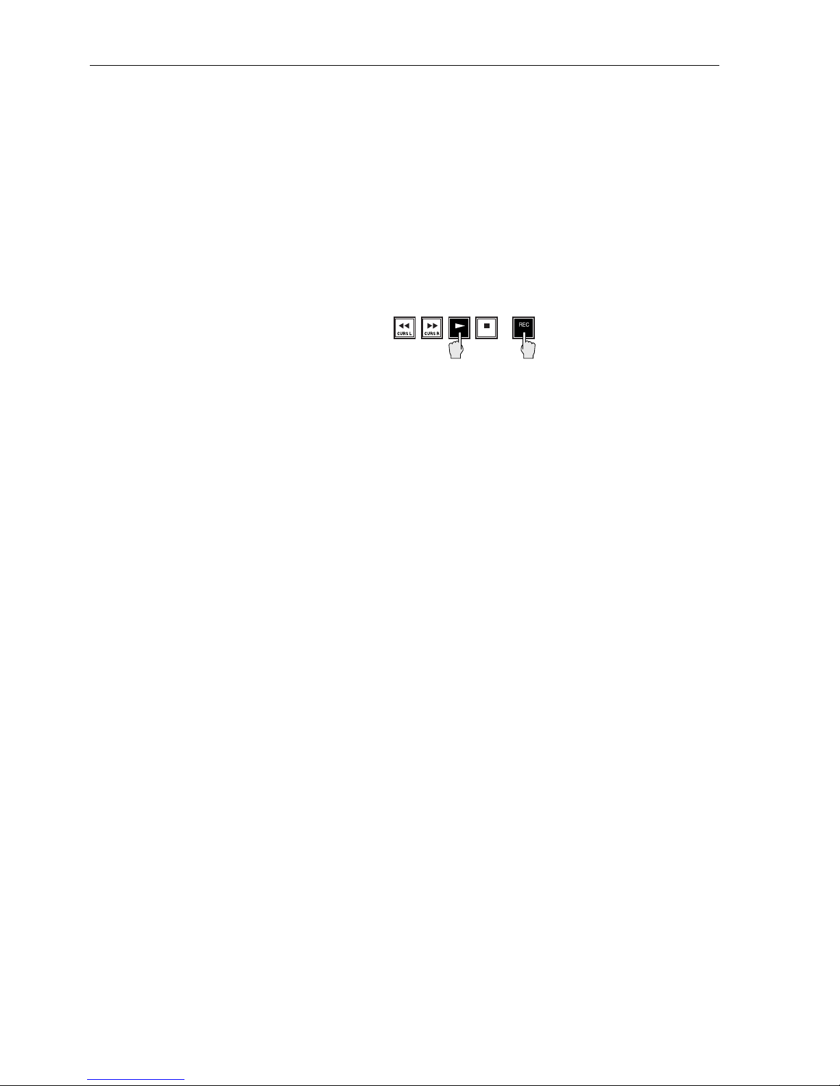
3.5 RECORDING OPERATION
Recording and playback use the transport keys on either the front panel or the
RE-8 session controller.
Please Note: Digital I/O recording and playback features are provided in §3.17.
3.5.1 Entering Record
To enter record, press/hold PLAY then press REC, or... press/hold REC and
press PLAY. The lights on the armed tracks stop flashing and are lit steadily.
Please Note: You may select the method used to enter Record (either PLAY +
REC, or just REC) on the Preferences menu, described in §4.3.4.5.
3.5.2 Punching In on Additional Tracks
RADAR provides on-the fly punch in for additional tracks while recording.
1. With RADAR already in record on some tracks, arm the desired
additional tracks. (The track arm lights of the current record tracks are on
solid; the track arm lights for the additional tracks will flash.)
2. To enter record on the additional armed tracks, press PLAY and REC
together. (All track arm lights are now on solid.)
Please Note: When tracks are armed during Record, they will not actually begin
recording until you press REC while holding PLAY. However, the Instant
Record feature, available on the Preferences menu, enables you to “drop” tracks
into record on the fly, simply by arming their tracks(s). This feature is described
in §4.3.4.5.
3.5.3 Punch Out (Dropping Out of Record)
Press PLAY to drop out of record with the transport still rolling, or press
STOP to stop both recording and the transport as well.
If you are monitoring playback material before and after the record punch-in,
the system switches seamlessly to the input material on the punch in, then back
to playback monitoring after the punch out.
If the operating conditions are right (determined by disk activity—see
§3.5.3.2), RADAR automatically provides seamless punch-out monitoring. In
all other cases, playback monitoring returns momentarily after the punch-out.
Standard Audible Punch Out: RADAR is a truly random-access recorder.
Since the act of punching out of record is, as far as RADAR can tell, a purely
random action, it cannot always have the underlying program material
immediately available for playback. (A tape machine can simply switch to the
playback head, and the correct playback material is right there!)
Edition 2 (Printed in Japan)
3-6 SECTION 3
Page 47

Please Note: On RADAR, the audio is always recorded seamlessly; it is only the
playback monitoring that takes a moment to return after the punch.
To emulate the features of tape recorders as closely as possible, RADAR provides
the punch-out playback instantly when possible. If the disks are playing and/or
recording on all tracks, the punch-out playback will return, but with a brief
delay. For more information about the necessary conditions for seamless punchout, see §3.5.3.2.
Seamless Punch Out Monitoring: RADAR’s disk drives support a maximum
of eight tracks of audio data, either playback or record. If you perform a punchin/punch out recording operation, the punch-out will be seamless (i.e. no
gap—a smooth switch between input and track monitoring), if the following
condition is met:
The punch-out monitoring will be seamless if the number of “free” disk
tracks equals or exceeds the number of tracks you are recording on that
disk unit.
Seamless punch-out will occur under these conditions:
• You have recorded four tracks of audio in a project, on tracks 1, 2, 3, and 4.
(Tracks 5 through 8 are not active in this project.)
• You rewind the transport, then arm tracks 3 and 4 to do an overdub. Before
you punch in, you will be monitoring tracks 1 through 4; on the punch in,
you will be playback monitoring tracks 1 and 2, and input monitoring on
tracks 3 and 4.
• When you punch out of record, tracks 3 and 4 switch instantly to playback
monitoring, while tracks 1 and 2 stay in playback monitor.
Seamless punch-out will NOT occur under these conditions:
• You have recorded on tracks 1 through 6.
• You rewind the transport, then arm tracks 1 through 4 for an overdub. When
you punch in, monitoring switches automatically from playback to input;
however when you punch out, there is a brief (sub 1 second) delay. The
seamless punch out does not occur because the disk’s throughput would have
exceeded its 8-track limit!
What if I REALLY have to get a seamless punch out here???
In these situations, you may make use of RADAR’s Mute Tracks feature,
available under the Edit menu. With Mute Tracks, you may temporarily “turn
off” tracks that are not in use, increasing the amount of disk drive throughput.
In the above example, you would use Mute Tracks to temporarily mute tracks 5
and 6; the disk overhead would allow you to punch in on tracks 1 through 4,
and get a seamless punch-out on all four tracks.
Please Note: Track Solo/Track Mute features are monitor functions, and do not
affect the amount of disk activity. You must use the Mute Tracks feature (Edit
menu, §7.13) to temporarily turn off unneeded tracks.
RECORDING & TRANSPORT OPERATION 3-7
Edition 2 (Printed in Japan)
Page 48

3.5.4 Record Safe Feature
The record-ready keys may be placed in and out of “RecSafe” mode using the
CLEAR/SAFE key on the RE-8.
Pressing this key turns off all REC-READYs; pressing it again returns the
previously rec-readied tracks to Rec-Ready status.
Please Note: Record Safe is available from the front panel through the Edit
menu.
3.5.5 Clear Rec-Ready (RE-8 only)
You may use the RE-8’s CLEAR/SAFE key to clear all Rec-Readied
tracks—simply press SHIFT (upper right corner of RE-8) then press
CLEAR/SAFE. This clears all Rec-Readied tracks (or all soloed tracks).
3.5.6 Recording to Timecode
RADAR will record while synced to an external timecode source, enabling
frame-accurate editing to almost any external source. Timecode features are
described in Section 5.
3.6 PLAYBACK OPERATION
3.6.1 Standard Playback
RADAR provides two playback modes—Forward Play and Reverse Play. In
addition, playback may be vari-speeded, or locked to an incoming sync source.
Please Note: Playback locked to external sync is described in §5.4.
Press PLAY (from either Front Panel or RE-8) to enter Play mode at any time.
Press STOP (from either location) to Stop playback.
3.6.2 Reverse Playback
To enter Reverse Play from the current location, press REW and PLAY
simultaneously. You may even do this while the transport is already in Play!
3.6.3 Playback to Timecode
RADAR will play back while synced to an external timecode source, enabling
frame-accurate lock to almost any external source. This feature is described in
§5.3.3.
Edition 2 (Printed in Japan)
3-8 SECTION 3
Page 49

3.7 TRACK SOLO FEATURE (RE-8 ONLY)
RADAR provides a Track Solo feature for auditioning individual or multiple
tracks on playback, while muting the remaining tracks. Track Solo is also useful
as a stereo-in-place solo function if your mixing desk is not capable of this.
Track Solo uses a dedicated key on the RE-8, with the track arm keys acting as
solo keys.
Please Note: Three Track Solo modes are provided—Additive, Interlock, and
Momentary. A description of each mode appears below. The desired mode may
be selected through the Preferences menu, described in §4.3.4.2.
3.7.1 Additive Solo Mode Operation
In Additive Solo mode, each time a track solo key is pressed, the track is
“added” to any others being soloed, as follows:
1. Press TRACK SOLO. The key’s LED will flash quickly and the LCD will
prompt:
SELECT TRACK
TO SOLO
2. Choose one or several tracks from the track arming group. When
selected, the track arming LEDs will blink for each soloed track. You may
now perform all transport operations except recording.
Please Note: During playback, the meters will show levels for only those tracks
soloed.
3. To take a soloed track out of Solo mode, simply press its track arm key
again. Its LED will turn off, and it will no longer appear on the meters.
4. To disable Track Solo, press the track solo key again. Its LED will go out
and you can resume normal operation. The tracks that were previously set
in Track Solo are remembered for the next time you engage this function.
3.7.2 Interlock Solo Mode Operation
In Interlock Solo mode (the system default; selectable from the Preferences
menu), every time a solo key is pressed, the previous soloed track(s) are taken
out of Solo.
If you want to solo more than one track, simply press and hold the first track
solo key, then select additional tracks to be soloed.
3.7.3 Momentary Solo Mode Operation
Momentary Solo mode (available from the Preferences menu) means that
track(s) are kept in solo for as long as their solo keys are held.
RECORDING & TRANSPORT OPERATION 3-9
Edition 2 (Printed in Japan)
Page 50

3.8 VARISPEED RECORDING/PLAYBACK
3.8.1 Varispeed Overview
Varispeed is used to change the speed (and pitch) of recording and playback.
Potential uses of Varispeed include: lowering the pitch of existing tracks during
an overdub session so a vocalist can sing in a more comfortable range,
thickening the voice by recording multiple tracks in altered pitches, and
matching the tuning of recorded tracks with difficult to tune instruments such
as a piano.
RADAR’s Varispeed can be adjusted in terms of the percent of deviation from
normal speed or cents (hundredths of a semitone) deviation from A440 Hz. The
range is variable from minus 15% or 241 cents to a maximum of plus 15%
depending on the sample rate you use for your recording.
Varispeed Variation/Ranges by Sample Rate:
Sample Rate Plus Minus
48 kHz 2.8% or 48 cents 43.75% or 995 cents
47.952 kHz 2.9 or 50 cents 43.69 or 993 cents
44.1 kHz 11.9% or 195 cents 38.77% or 848 cents
44.056 kHz 12% or 196 cents 38.71% or 847 cents
32 kHz 54.2% or 750 cents 15.62% or 293 cents
3.8.2 Changing Pitch With Varispeed
1. Press VARISPEED. The system will respond with:
V-SPEED: 00.00%
UNITS: PERCENT
2. Press UP or DOWN to raise or lower the percentage value. On the RE-8
you may enter a number using the plus/minus and numeric keys, or use the
jog wheel to dial the number up or down. (The cursor keys and/or jog wheel
provide instant speed change—if you use the numeric entry method, the speed
change occurs upon pressing ENTER.)
3. Press VARISPEED again to activate and return to Ready mode. To
enable and disable, press VARISPEED twice to enable, twice to disable.
This can be done during any transport mode, including Record.The LED on
the VARISPEED key indicates On/Off status.
Please Note: To check a Varispeed value without turning the function Off, press
VARISPEED, then CANCEL (RE-8) or MENU/CANCEL (front panel).
3.8.3 Changing Varispeed Units
1. Press VARISPEED.
2. Press the cursor right key to move the cursor from the varispeed value
field to the units field.
3. Use the UP/DOWN keys to change from PERCENT to CENTS.
Edition 2 (Printed in Japan)
3-10 SECTION 3
Page 51
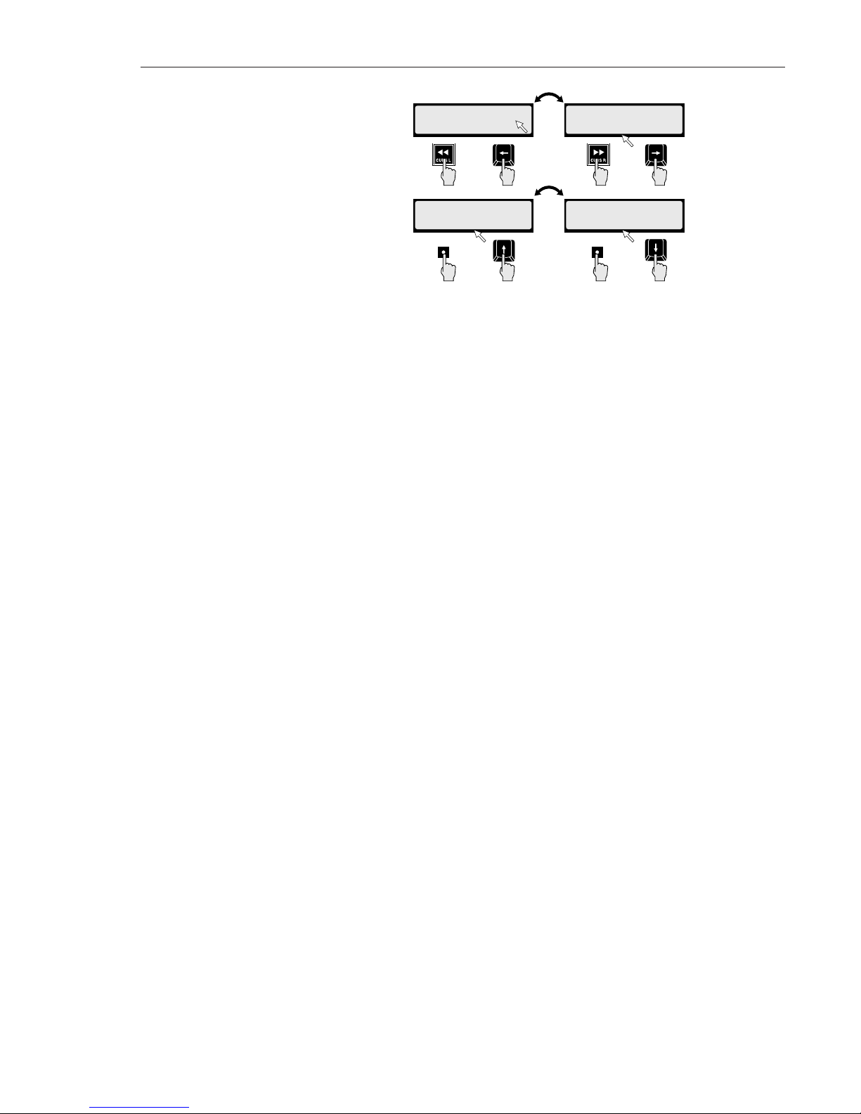
Press the cursor left key to move the cursor back to the value field and use
UP/DOWN keys (or jog wheel) to adjust the amount of varispeed.
3.9 AUTO INPUT
3.9.1 Auto Input Overview
AUTOmatic INPUT monitor selects whether or not program material on record-
readied tracks is monitored during playback. This feature has been provided because
different recording situations require different monitoring strategies.
Auto Input manages the monitor status of rec-readied tracks by monitoring existing
track material during Play. When you enter Record, you will hear input material
before switching back to track monitor when you exit Record. At other times (while
the transport is in any mode besides Play), the inputs are monitored. (When Auto
Input is OFF, the input from any tracks armed will be monitored at all times, including
record and playback.)
3.9.2 Turning Auto Input On and Off
Press AUTO INPUT to engage and disengage Auto Input. The LED will light
indicating automatic input monitoring is enabled. This function defaults to On
when RADAR powers up and, in most re cording circumstances, may be left On.
V-SPEED: +00.00%
UNITS: PERCENT
_
V-SPEED: +00.00%
UNITS: PERCENT
_
V-SPEED: +0000c
UNITS: CENTS
_
V-SPEED: +00.00%
UNITS: PERCENT
_
Front Panel
Front Panel
Front Panel
Front Panel
RE-8
RE-8
RE-8
RE-8
UP/
YES
DOWN/
NO
RECORDING & TRANSPORT OPERATION 3-11
Edition 2 (Printed in Japan)
Page 52

3.10 AUTO PUNCH
The Auto Punch function is useful when you need to punch in and out at
precisely timed location points. To get the absolute best performance of a single
word or note, for example, RADAR can handle the punching while you can
concentrate exclusively on monitoring the performance.
Auto Punch uses the Mark In and Mark Out times as punch points. This
function may be initiated from the Front Panel or from the RE-8.
3.10.1 Setting-up for an Auto Punch
From the RE-8:
1. Using the jog wheel, transport or calculator, locate to the section you
will be Auto Punching over.
2 Press MARK IN and OUT to define the beginning and end points,
respectively, of the section.
3. Arm the tracks to record upon using the track arm keys. Press AUTO
PUNCH. The AUTO PUNCH LED will glow solid.
4. Locate before the section using the transport or locate functions.
5. Hold PLAY and press REC. RADAR will automatically enter and exit
Record when the Mark In and Out points are reached.
Press AUTO PUNCH to enable or disable this function.
Auto Punch from the Front Panel:
1. Using the transport or Recall Loc functions, locate near the beginning
of the section you will be Auto Punching over.
2. In Play, press and hold MARK LOC and then press UP and DOWN to
define the beginning and end points of the Auto Punch section. Arm
the tracks to record upon using the track arm keys.
3. Hold MENU/CANCEL and press AUTO PUNCH. The AUTO
PUNCH LED will indicate On or Off status whenever the
MENU/CANCEL key is pressed and held.
4. Locate to the beginning of the section using the transport or locate
functions.
5. Hold PLAY and press REC. RADAR will automatically enter and exit
Record when the Mark In and Out points are reached.
To disable and re-enable this function, hold MENU/PREV and press AUTO
PUNCH.
Edition 2 (Printed in Japan)
3-12 SECTION 3
Page 53

3.10.2 Editing Auto Punch In and Out locations
There are two ways to fine tune the Auto Punch In and Out (Mark In and Mark
Out) locations. On the RE-8 only, you may use the jog wheel to scrub audibly
to the exact location and press either of the MARK IN or OUT keys. On both
the RE-8 and front panel, you may also use the Edit Loc function to directly
nudge the SMPTE times of the Mark points by frames or subframes.
Please Note: Complete procedures for scrub/shuttle operation are provided in
§3.12.2.
3.11 UNDO/REDO FUNCTIONS
Probably one of the most useful features of RADAR is the ability to undo a
previous recording action or audio edit. You may undo a recording operation
even after you use the transport controls to locate, play and rewind. The new
take becomes permanent as soon as a you enter Record again.
There is no limit to the number of recorded tracks that an Undo operation can
be performed upon. You can undo a single syllable recorded on one track or an
entire band on all 24. The only limiting factor is the amount of disk space
remaining when you record. This is because when RADAR records over
previous audio, it is adding to the data on the disk drive, not overwriting like a
tape machine. There is always a copy of the new and old takes as long as there is
space for both.
Along with the Undo function is the Redo function. Redo will “undo” the
Undo if you should decide to keep the new part after all.
Performing an Undo or Redo from the RE-8:
1. Press UNDO after performing a Record or Edit operation. The display
will read:
UNDO RECORD?
NO Y
ES
Please Note: RADAR shows the last operation by name in the undo or redo
menu. Thus, if the last action was a Paste, the menu would read: “UNDO
PASTE?”
2. Press ENTER. RADAR will undo the previous operation. Press CANCEL
if you want to abort. Repeat this procedure to redo.
From the Front Panel:
1. Hold MENU/ESC, then press UNDO.
2. Press STOP/ENTER.
3. Press MENU/ESC if you want to abort.
Repeat this procedure to redo.
Please Note: If there is no function to undo, the system will display:
NOTHING TO UNDO
PRESS ANY BUTTON
RECORDING & TRANSPORT OPERATION 3-13
Edition 2 (Printed in Japan)
Page 54

3.12 LOCATING IN THE RECORDED MATERIAL
RADAR provides five methods for locating in the recorded material:
• Fast-Wind keys
• “Cue to Audio”
• Shuttle/Jog
• Autolocator Features
• Direct Time Entry
3.12.1 Cueing with Fast Forward and Rewind
RADAR is a random access device with any location point able to be cued
virtually instantly. We have also retained Fast Wind functions for tape machine
users.
Fast Forward/Rewind Operation: Press either the FFWD (>>) or RWD (<<)
key once to fastwind the transport. (Normally, the fast wind rate is 6 times
normal speed; this may be changed on the Preferences menu—see note below.)
Press either key twicewithin 1 second to fastwind at 3 times the regular fast
wind speed (normally 18 times normal play speed). Press the fast wind key again
to slow the transport to the standard fast wind rate.
During these modes, the LCD shows the changing SMPTE time and the names
and numbers of any programmed location points passed during the wind.
Please Note: The standard fast wind speed is set to 6 times normal play speed.
You may change this rate on the Preferences menu—described in §4.3.4.6.
“Cue to Audio” Using Fast Wind Keys: RADAR provides a powerful “Cue to
Audio” feature that will, when selected “skip” the current transport location to
the beginning of the current audio section, or—if in a silent section, “Cue to
Audio” will locate you to the next audio on the system. This feature is very
convenient for locating takes in a project that may be separated by large
unrecorded gaps. Cue-To works by locating ahead (or back) to the nearest
transition from audio program to silence. If Track Solo is active, this feature
operates using just the soloed tracks.
To skip to the end of the current audio section: Press RECALLLOC followed
by FFWD to cue to the next transition of audio. Or...
Press RECALLLOC followed by RWD to locate to the previous transition.
If you are currently in a silent section, RADAR locates to the head (or tail) of
the silent section.
3.12.2 Jog/Shuttle Mode (RE-8 only)
RADAR’s Jog/Shuttle modes provide fast, precise location in recorded material.
Shuttle mode uses the jog wheel to vary the speed and direction of audio for
locating points; Jog mode allows you to “scrub” the audio to find exact
locations.
Edition 2 (Printed in Japan)
3-14 SECTION 3
Page 55
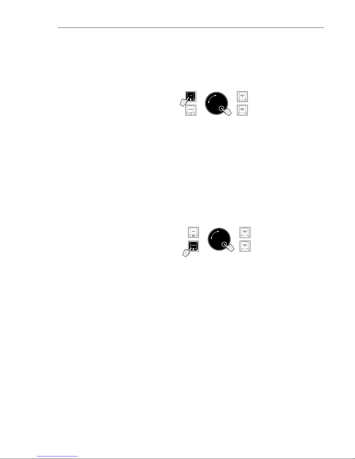
Please Note: The jog wheel may also be used as a convenient input device when
prompted by the LCD to enter a numeric value, and also as a means of scrolling
through RADAR’s menus. When used as an input device, turning the wheel to
the right increases the value, and turning it to the left decreases the value.
Entering Jog Mode: Press the JOG key to the left of the wheel to engage Jog
mode:
Turning the wheel clockwise or counterclockwise produces variable speed
playback for as long as you continue turning it. When you stop turning the
wheel, playback will stop. The speed of playback varies from scrub where you
can accurately locate the first transient of an audio waveform by rocking the
wheel gently forward and backward to slightly above normal playback speed.
Jog “Bump”: You may “bump” the current location while in Jogby pressing the
cursor left or right keys. Each cursor press will nudge the jog location by the
smallest possible wheel increment.
To exit Jog mode, press any key (including the JOG key).
Entering Shuttle Mode: Press the SHUTTLE key (located below JOG) to
engage Shuttle mode:
Shuttle produces playback at variable speeds like Jog with one difference; when
you stop turning the wheel, playback continues at the current speed until you
move the wheel again or press a transport key.
To exit Shuttle mode, press any key including the SHUTTLE key.
2
1
1
2
RECORDING & TRANSPORT OPERATION 3-15
Edition 2 (Printed in Japan)
Page 56
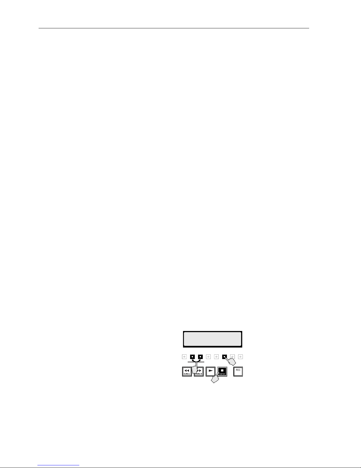
3.13 AUTO LOCATION
Because RADAR is a hard disk recorder, you can instantly cue to a location
without having to wait for rewind or fast forward. In this way, the program
material is more like a phonograph record than a tape machine because you can
drop the needle at the precise moment from which you want to start playback.
You may program up to 99 location points with the ability to assign and edit
each individual name and SMPTE location.
There are also two temporary points called Mark In and Mark Out. These are
used to designate sections for Auto Punch and Editing as well as being useful as
quick locate points that you will not need permanently.
3.13.1 Programming a New Auto Location Point
On the RE-8 or Front Panel:
1. Press MARK LOC once for each location point you wish to store.
Programming may be done at any time during playback, recording, or
stopped modes, and you may store multiple location points in one pass.
2. To program the temporary Mark points, press MARK IN and MARK
OUT. Each subsequent key press overwrites the previous point.
RADAR will automatically assign location numbers in the order in which they
were programmed. For example: you hav e just programmed a locate point at
01:00:00:00 and RADAR has assigned it as #1. Next, you program another point
at 01:00:05:00 and it is assigned point #2. If you then rewind a bit and press
MARK LOC at 01:00:03:00 this would become locate point #3. The most
recently programmed point is set as the current locate point. You may also choose
to enter new location points using the Edit Loc function described in Editing a
Locate, Mark In or Mark Out point belo w. This may be preferable if you already
know the SMPTE times at which you would like to have location points.
Please Note: The RENUMBER LOCATES menu item (under the Projects
menu) re-numbers all Locate points in the current Project in SMPTE order. See
§4.3.2.11 for more information about this feature.
3.13.2 Recalling Marked Locate Points from the Front Panel
Refer to to the following diagram for front panel operation:
1. Press RECALL LOC. The key lights, and the LCD changes to show a
flashing R at its upper right corner.
2. Use UP/YES and/or DOWN/NO to scroll through the numbered locate
points until you come to the desired one, then...
3. Press ENTER (which, on the front panel, is also the STOP key).
AUTO
PLAY
01:01:24:41.26 R
LOC:03
3
1
2
HRS/BAR MIN/BEAT SEC/STEP FRM SUB
MENU/
CANCEL
UP/
YES
DOWN/NOMARK
LOC
AUTO
INPUT
RECALL
LOC
EXT
SYNC
VARI-
SPEED
2nd
FUNC
AUTO
PUNCH
CYCLE
EDIT
LOC
UNDO/
REDO
Edition 2 (Printed in Japan)
3-16 SECTION 3
Page 57
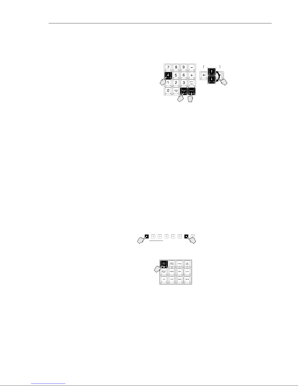
3.13.3 Recalling a Locate Point from the RE-8
The RECALL LOC key is on the numeric keypad near the center of the RE-8.
1. Press RECALL LOC.The LCD will show a flashing R at its upper-right
corner, as shown above.
2. Use the cursor up and down arrows to scroll through the locate points,
or...
Enter the number of the locate point using the numeric keypad.
SHORTCUT: With the RE-8, you have the option of directly entering the
number of the location point in the calculator or entering the first letter of
any named location point using the QWERTY keyboard.
3. Press ENTER to process the locate.
3.13.4 Auto Play after Locate
RADAR begins playback automatically after a locate if Auto Play is enabled.
This is useful for quickly auditioning certain sections of a performance using
Recall Loc without having to press PLAY every time. This is also useful when
you are recording; instead of pressing STOP to halt Record, you could press
RECALL LOC with Auto Play engaged and immediately hear playback of the
take you have just recorded.
Auto Play is available from the front panel by holding the 2nd FUNC key, then
pressing the EXT SYNC/AUTO PLAY key:
Auto Play is also available from the RE-8 as a lighted key in the utility group:
If Auto Play is turned on, every time you locate the transport using the Recall
Loc feature, the system will play automatically. As mentioned above, this can be
a time saver during repeated overdubs and voice-over operations.
MENU/
CANCEL
UP/
YES
DOWN/NOMARK
LOC
AUTO
INPUT
RECALL
LOC
EXT
SYNC
VARISPEED
2nd
FUNC
AUTO
PUNCH
CYCLE EDIT
LOC
AUTO
PLAY
UNDO/
REDO
1
2
3
2
DISK SPACE REMAINING
RECORDING & TRANSPORT OPERATION 3-17
Edition 2 (Printed in Japan)
Page 58

3.13.5 Editing a Locate, Mark In or Mark Out Point
Using the Edit Loc function, you can change the name and SMPTE time of any
locate point or change the time of any Mark In or Mark Out point. You can
also enter new location points directly or delete them. All Edit Loc operations
may be performed during Play or Stop transport modes. For more information
on Mark In and Out see §6.12.
Please Note: Edit Locate features use the EDITLOC key, in the Utility section
of the RE-8, or as the 2nd function of the RECALL LOC key on the front
panel.
From the RE-8:
1. Press EDIT LOC.The LCD displays the EDIT, DELETE, NEW, and
SWAP options, along with the current locate point (if any).
EDIT DEL NEW SWP
LOC:
2. Select the operation you require (Edit, Delete, New, or Swap) using the
right and left arrows, then press ENTER. The system will respond with a
dialog that resembles Ready mode with the addition of a letter (E for Edit,
D for Delete, or N for New) in the upper right-hand corner.
3. Select the location point you want to edit by number (using the
numeric keys) or, in the case of the MARK IN/MARK OUT keys,
simply press the desired mark key.
01:09:18:12.78
LOC:03 GO GAL!
4. Use the cursor left/right keys to move among the fields—you may use
the cursor up/down keys to make changes, or use the numeric keypad
to enter numbers, or, use the jog wheel to change the numbers.
5. To assign or edit the name of the location (in EDIT or NEW only),
press cursor right until the cursor is to the right of the location
number.This places the cursor beneath the first letter of the name. Use the
QWERTY keyboard to type or edit the nine character name.
Please Note: The jog wheel may be used to enter non-alphabet characters. In
the Delete dialog, you may change only the location number to be deleted. Use
the cursor up/down keys or the jog wheel to do this.
6. Swap only. The Swap function provides a different screen when selected:
SWAP: 03
WITH: 01
Use the cursor up/down keys to select the point(s) to be swapped—these
include any numbered autolocator points, plus the Mark In and Mark Out
points. Use the cursor left/right keys to move between rows on the LCD.
7. Press ENTER to complete the Edit, Delete, New, or Swap operation
and return to the initial Edit Loc dialog.
or...
Press EDIT LOC again to return to Ready mode or choose one of the
Edit, New or Delete options.
Edition 2 (Printed in Japan)
3-18 SECTION 3
Page 59

From the Front Panel: This is essentially identical in operation as the RE-8
except for the following:
1. Hold MENU/CANCEL and press EDIT LOC to show the initial
dialog.
2. Use the >>/CURS R and <</CURS L key instead of the cursor keys to
move the cursor to the desired field.
3. Use the STOP/ENTER key to accept an option highlighted by the
cursor, and to complete an operation.
3.13.6 Naming Locate Points from the Front Panel
To assign or edit a name, enter the first letter in the name by pressing the
UP/DOWN keys to scroll to the letter you want. Press the FFWD key to move
the cursor to each of the next fields and select letters as before. Use the RWD
key to move the cursor to a previous field.
RECORDING & TRANSPORT OPERATION 3-19
Edition 2 (Printed in Japan)
Page 60
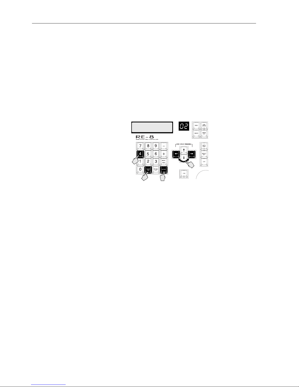
3.14 LOCATING VIA DIRECT TIME ENTRY (RE-8 ONLY)
This function allows you to cue the transport to an exact SMPTE location by
typing it in on the RE-8’s numeric keypad. This function is available during any
transport mode, including Record.
1. Press ENTER TIME. The LCD will change to show the captured SMPTE
time on the bottom line and the current time on the top line. If the
transport is stopped, these numbers will be the same. In Play, the number
on the top line will continue to increment. The cursor will be flashing
beneath the frames or seconds field of the captured time.
2. Enter the SMPTE time you want starting with frames, then seconds
and finally minutes and hours. (You may also use the arrow keys to move
the cursor among the fields, so you may enter times directly.)
3. Press ENTER to accept the new SMPTE location. RADAR will cue to
the new location and return to Ready mode.
+/- Shortcut: You may simply press the keypad + or – key followed by a
numeric entry—this will add (or subtract) the entered value from the
current location.
Please Note: You may change the “default” field of Enter Time so that when
you select the function, the cursor is on the seconds field rather than the frames
field. For information on changing this default setting, refer to §4.3.4.1.
01:32:51:12.24
00:00:00:04.00
_
1
2
3
2
HRS/BAR MIN/BEAT SEC/STEP FRM SUB
Edition 2 (Printed in Japan)
3-20 SECTION 3
Page 61

3.15 CYCLE
Cycle continuously plays back audio between the Mark In and Mark Out
points. This feature is useful for repeating audio sections while you change
equalization or rehearse a Punch In.
Cycle from the RE-8:
1. Locate to the start of the section you want to cycle between using
transport and jog wheel.
2. Press PLAY.
3. Press MARK IN at the start of the section to repeat.
4. Press MARK OUT at the end of the section.
5. Press CYCLE. Playback will automatically cycle between the two points.
6. Press CYCLE again to disable.
Cycle from the Front Panel:
1. Locate to the start of the section you want to cycle.
2. Press PLAY.
3. Hold MENU/CANCEL and press UP and DOWN at the start and end
of the section respectively.
4. Hold MENU/CANCEL and press CYCLE. Playback will automatically
cycle between the two points.
5. Hold MENU/ESC and press CYCLE again to disable.
RECORDING & TRANSPORT OPERATION 3-21
Edition 2 (Printed in Japan)
Page 62

3.16 PRE/POST ROLL
Preroll allows you to cue to a user definable time previous to any recalled
location point. It is useful when you need to hear the audio leading up to the
location point for Punch Ins and do not want to add any more location points.
Preroll also works with the Cycle function by providing an extra few seconds of
lead-in before the marked beginning and end points.
Postroll works along with the Cycle mode to provide extra play-out time after
the end point is reached.
Please Note: Preroll is only available using the RE-8 session controller.
Only from the RE-8:
1. Press PRE ROLL. The dialog will show the default settings for both PRE
and POST ROLL at two seconds each.
2. Press PRE ROLL again if you accept the default settings.
If you wish to edit these settings, press the left or right arrows to locate to
the appropriate field and use the UP/DOWN keys to change them.
3. Press PRE ROLL to accept the new settings and return to Ready mode.
To disable Preroll, press PRE ROLL twice from Ready mode. To re-enable
without changing, press twice again.
Edition 2 (Printed in Japan)
3-22 SECTION 3
Page 63

3.17 DIGITAL I/O OPERATION
RADAR provides both AES/EBU and S/PDIF stereo digital interfaces, enabling
up to two tracks of digital audio to be recorded or output. The ADATLink®
option, available from Otari, connects your RADAR to up to three ADATformat digital recorders.
RADAR’s menu interface is used to specify the input and/or output track(s),
and also the format to be used. Several conditions apply to Digital I/O
operation:
• Digital I/O may be recorded to/output from two tracks that share the same
disk drive. Track pairs that split across 8-track drive boundaries are not
permitted (i.e. tracks 8 and 9 cannot be used as a digital I/O channel pair).
• If tracks are patched to the digital inputs, the corresponding analog inputs are
inactive. (However, RADAR tracks patched to digital outputs are still routed
to the corresponding analog outputs.)
• RADAR’s user interface permits you to select a track number of 0—this
signifies that no track will be patched to the digital channel.
Please Note: In both the AES/EBU and S/PDIF digital formats, digital
wordclock is encoded with the audio on the same cable. Therefore, in normal
operation, no additional digital wordclock is required.
Digital I/O Operation: Connect a digital input source (either format) to the
RADAR’s rear panel, according to the following diagram:
Digital I/O Format/Routing Selection from the RE-8:
1. Press DIGITAL I/O. The system will respond with:
DIG I/O ROUTING:
AES/EBU,S/PDIF
2. Use the cursor up/down keys (or the jog wheel) to select the desired
format (“AES/EBU, S/PDIF” or “ADATLINK”), then press ENTER. (If
you selected “AES/EBU, S/PDIF”, the system responds with:)
DIG IN L:11 R:12
OUT L:11 R:12
3. Select the desired input (and output) tracks. Use the cursor left/right
keys and the up/down keys to make your selection(s).
Remember that the tracks must be from the same 8-track disk drive block
(although they need not be adjacent to each other). Also, specifying Track
00 means the channel will be inactive.
SYNC
REFERENCE
IN OUT OUTIN
AES/EBU
OUTIN
S/PDIF
OUTIN
LTC
SMPTE/EBU
MIDI PC KBD
OUTTHRU IN IN
RADARLINK CONTROL
ON OFF
75Ω
RECORDING & TRANSPORT OPERATION 3-23
Edition 2 (Printed in Japan)
Page 64

Routing Selection from the Front Panel:
1. Press MENU/CANCEL to display the Main menu. Using the up/down
keys, scroll to the SYSTEM item (if not already displayed), then press
ENTER. The system will respond with:
MAIN MENU:
S
YSTEM MENU
2. Press ENTER. Use the up/down keys to select the DIGITAL I/O
submenu:
MAIN/SYS MENU:
D
IGITAL I/O
3. Press ENTER. The system will respond with:
DIG I/O ROUTING:
AES/EBU,S/PDIF
4. Use the up/down keys to select the desired format, then press ENTER.
(If you selected “AES/EBU, S/PDIF”, the system responds with:)
DIG IN L:11 R:12
OUT L:11 R:12
5. Select the desired input (and output) tracks. Use the cursor left/right
keys and the up/down keys to make your selection(s).
Remember that the tracks must be from the same 8-track disk drive block
(although they need not be adjacent to each other). Also, specifying Track
00 means the channel will be inactive.
Enabling Digital I/O Operation:
1. To enable Digital I/O operation, press OFFSET/SYNC (RE-8) or EXT
SYNC (front panel). The system will respond with the Sync Source dialog
box, below. Use the cursor keys (or jog wheel) to select SYNC SOURCE:
DIGITAL:
SYNC SOURCE:
D
IGITAL
2. Press ENTER. The system responds with a format query:
DIG I/O FORMAT:
A
ES/EBU
3. Select the desired digital I/O format (AES/EBU, S/PDIF, or
ADATLINK), then press ENTER. The external sync key(s) will flash to
indicate that digital I/O is now active.
Start the digital input source (if selected), or press PLAY to enable the digital
output. If digital input is active, you will see levels activity on the digital input
channel(s) you selected.
Edition 2 (Printed in Japan)
3-24 SECTION 3
Page 65

Edition 2 (Printed in Japan)
4.1 GENERAL ...................................................4-3
4.2 MENUS OVERVIEW..........................................4-3
4.2.1 RADAR Menu—Top Level ............................4-3
4.2.2 Moving Around in Menus............................4-3
4.2.2.1 Menu Operation using the RE-8 ....................4-3
4.2.2.2 Front Panel Menu Operation.......................4-3
4.2.3 Menu Structure......................................4-4
4.2.4 Entering/Exiting the Menu ...........................4-5
4.2.5 Scrolling & Selecting within the Menu.................4-6
4.2.6 Editing Values in a Dialog Window...................4-6
4.3 A TOUR OF THE MENU......................................4-7
4.3.1 System Menu .......................................4-7
4.3.1.1 System Version ..................................4-7
4.3.1.2 Digital I/O.....................................4-7
4.3.1.3 Sync Output ....................................4-7
4.3.1.4 Configure Disks .................................4-7
4.3.1.5 Set Time & Date.................................4-8
4.3.1.6 Upgrade System.................................4-8
4.3.2 Project Menu .......................................4-8
4.3.2.1 Backup/Restore.................................4-8
4.3.2.2 GOTO Project ..................................4-8
4.3.2.3 Create Project...................................4-9
4.3.2.4 Name Project...................................4-9
4.3.2.5 Copy Project....................................4-9
4.3.2.6 Delete Project...................................4-9
4.3.2.7 Sample Rate....................................4-9
4.3.2.8 Start Time ......................................4-9
4.3.2.9 Sync Offset.....................................4-9
4.3.2.10 Reclaim Space................................4-10
4.3.2.11 Renumber Locates .............................4-10
4.3.2.12 Erase All Disks ................................4-10
4.3.3 Edit Menu.........................................4-11
4.3.3.1 Undo/Redo ...................................4-11
4.3.3.2 Modify Edit....................................4-11
4.3.3.3 Edit Features (Cut/Copy/Paste/Move/Erase/Loop
/Slide/Reverse)................................4-11
4.3.3.4 Listen.........................................4-11
4.3.3.5 Mute Tracks ...................................4-11
4.3.3.6 Import *.WAV Files .............................4-12
4.3.3.7 Crossfade Time ................................4-12
4.3.3.8 Record Safe ...................................4-12
Section 4 RADAR Menu Operation
Page 66

Section 4—Table of Contents, Continued
4.3.4 Preferences Menu..................................4-13
4.3.4.1 Default SMPTE Field ..........................4-13
4.3.4.2 SMPTE Lock Speed .............................4-13
4.3.4.3 Track Solo Mode ...............................4-13
4.3.4.4 Low Disk Warning ..............................4-14
4.3.4.5 Slide Time Units ................................4-14
4.3.4.6 Record Mode..................................4-14
4.3.4.7 Fast Forward/Rewind Rate.......................4-15
4.3.4.8 Peak Hold Time ................................4-15
4.3.4.9 Clip Hold Time.................................4-15
4.3.4.10 Save State Delay..............................4-15
4.3.5 Diagnostics Menu..................................4-16
4.3.5.1 Scan SCSI Bus.................................4-16
4.3.5.2 Mount / Unmount (File System)....................4-16
4.3.5.3 Disk Diagnostics................................4-16
4.3.5.4 Show Free RAM................................4-16
4.3.5.5 Debug/Error Logging ...........................4-16
4.3.6 Shutdown RADAR ..................................4-17
Edition 2 (Printed in Japan)
4-2 SECTION 4
Page 67
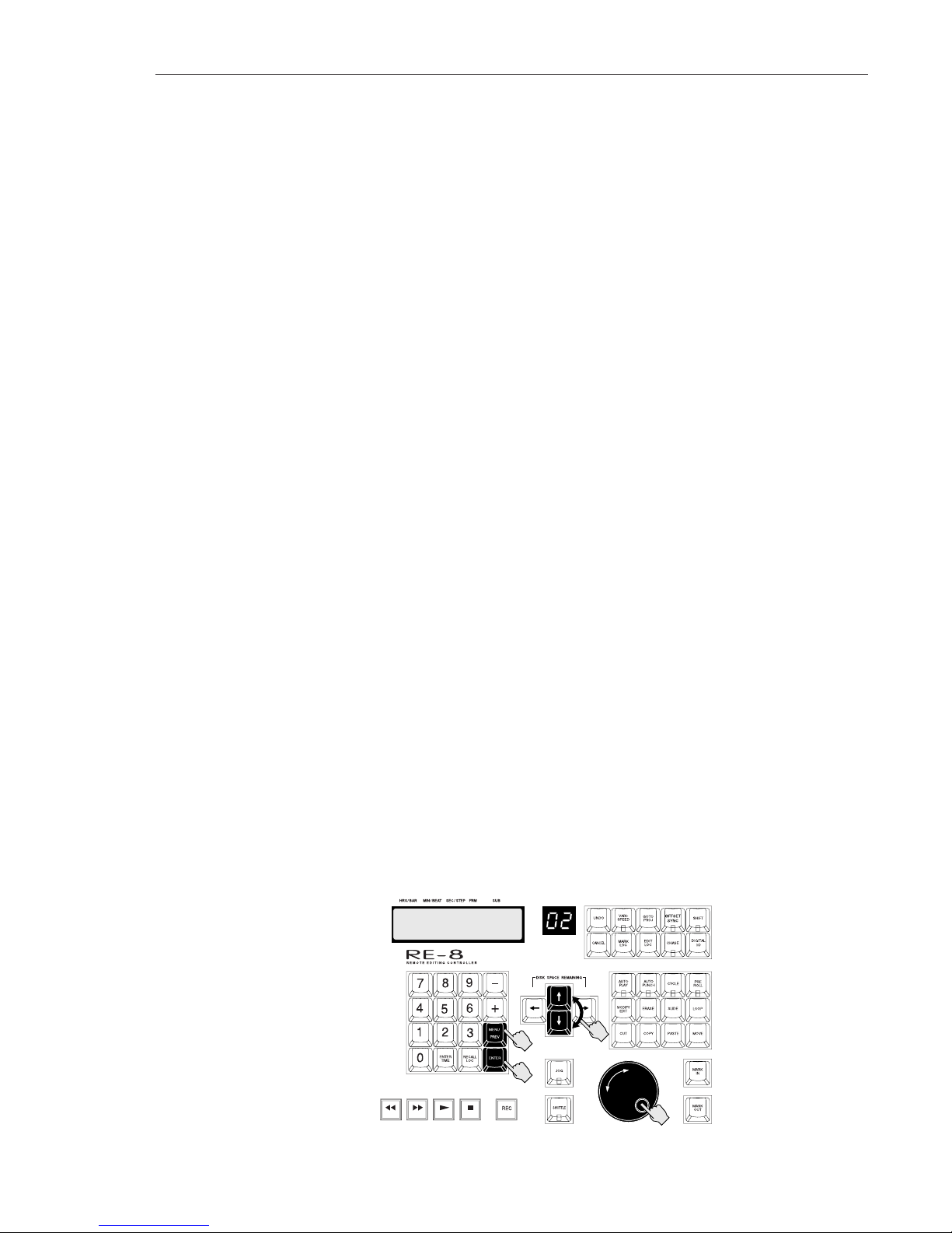
4.1 GENERAL
RADAR provides a set of menus on the LCD for access to features that are used
less often and do not require their own dedicated keys.
This section provides a description of general menu operation, and a complete
description of each item in the menu structure. For menu item descriptions
requiring detailed instructions, the appropriate paragraph reference is provided.
4.2 MENUS OVERVIEW
RADAR’s menu system consists of layers of topics ranging from general
categories (five) to more specific functions; many of these end in what we call a
“dialog”, which is simply a menu that requires your input.
4.2.1 RADAR Menu—Top Level
When you press MENU on the RE-8 or MENU/CANCEL on the front panel,
the LCD screen presents you with a Main menu, which includes the most
general listing of topics:
SYSTEM MENU
PROJECT MENU
EDIT MENU
PREFERENCES MENU
DIAGNOSTIC MENU
SHUTDOWN RADAR
From these choices, you may select a more specific layer called a submenu. And,
from the submenu, you may be presented with an additional submenu.
4.2.2 Moving Around in Menus
Controlling the selection of submenus and changing values is done with the jog
wheel or arrow keys on the RE-8 session controller, or the UP/YES or
DOWN/NO, <</CURS Land >>/CURS R keys on the front panel. These
methods are described below.
Menu Operation using the RE-8: The MENU/PREVand ENTER keys, plus
the cursor keys, are used to enter/exit the menu and to travel up and down
through the menu system, as shown. The jog wheel may be used to scroll
quickly through menus—and when a menu item is selected requiring input, the
jog wheel may be used to “dial in” an value.
MAIN MENU:
PROJECT MENU
2
1
3
2
RADAR MENU OPERATION 4-3
Edition 2 (Printed in Japan)
Page 68
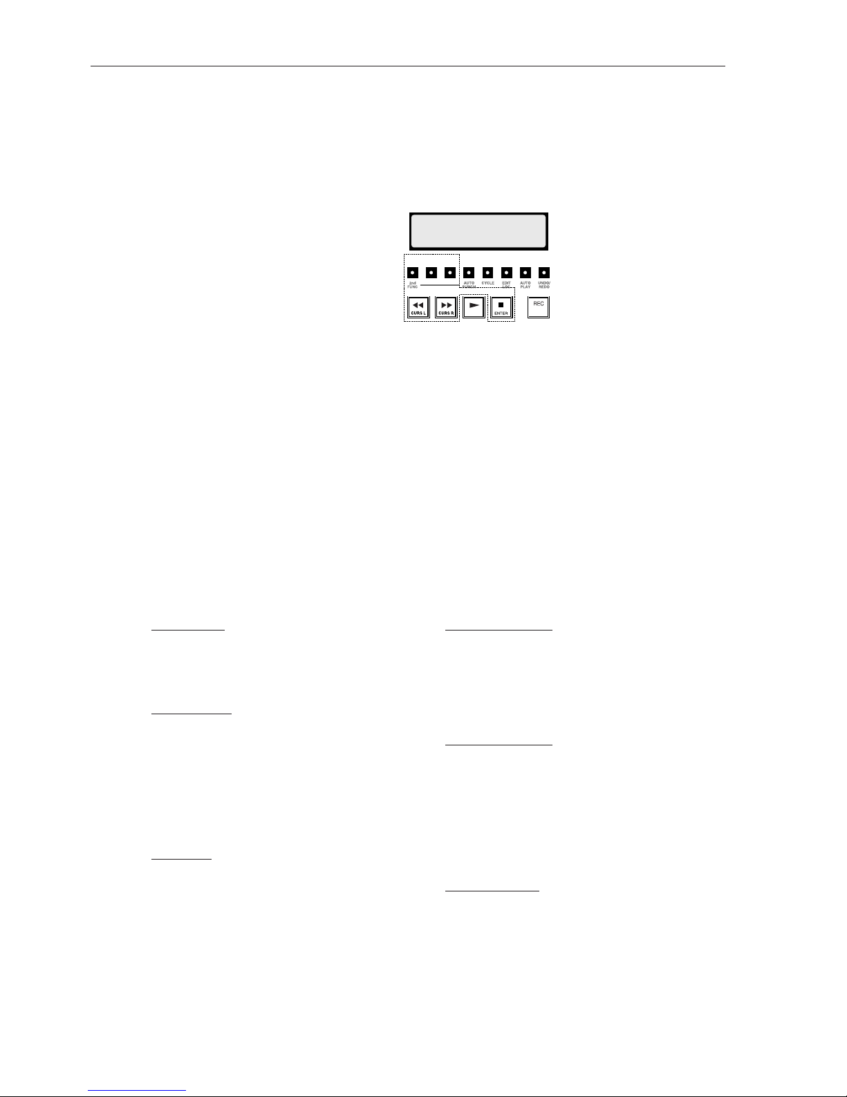
Front Panel Menu Operation: In order to provide menu access and navigation
from RADAR’s front panel with a minimum of extra keys, the transport keys
have two functions.
The FFWD, RWD and STOP keys from the transport group each perform an
alternate function while in Menu mode. These keys are printed with two
legends indicating their dual functions:
• RWD doubles as the cursor left control. This is for cycling backward
through options shown in the LCD prompt.
• FFWD doubles as the cursor right control. This is for cycling forward
through options shown in the LCD prompt.
• STOP doubles as the ENTER key. You may use the STOP/ENTER key to
accept a choice offered in the LCD prompt.
4.2.3 Menu Structure
The Main menu is available, from the RE-8, by pressing MENU/PREV. Or,
you may press MENU/CANCEL on the front panel. Use the up and down keys
(front panel) or the jog wheel (RE-8) to scroll through the listings.
Please Note: The major categories are underlined—to make selections from a
major category, press ENTER while it is displayed, then use the cursor up/down
arrows to move through the submenus.
MAIN MENU:
PROJECT MENU
HRS/BAR MIN/BEAT SEC/STEP FRM SUB
MENU/
CANCEL
UP/
YES
DOWN/NOMARK
LOC
AUTO
INPUT
RECALL
LOC
EXT
SYNC
VARI-
SPEED
Edition 2 (Printed in Japan)
4-4 SECTION 4
SYSTEM MENU SYSTEM VERSION
SHOW DISK SPACE
DIGITAL I/O
SYNC OUTPUT
CONFIGURE DISKS
SET TIME & DATE
UPGRADE SYSTEM
PROJECT MENU BACKUP MENU
RESTORE MENU
GOTO PROJECT
CREATE PROJECT
NAME PROJECT
COPY PROJECT
DELETE PROJECT
SAMPLE RATE
START TIME
SYNC OFFSET
RECLAIM SPACE
RENUMBER LOCATES
ERASE ALL DISKS
EDIT MENU UNDO/REDO
MODIFY EDIT
CUT
COPY
PASTE
MOVE
ERASE
LOOP
SLIDE
REVERSE
LISTEN
MUTE TRACKS
IMPORT *.WAV
CROSSFADE TIME
RECORD SAFE
PREFERENCES MENU DEFAULT SMPTE FIELD
SMPTE LOCK SPEED
TRACK SOLO MODE
LOW DISK WARNING
SLIDE TIME UNITS
RECORD MODE
FFWD & REW RATE
PEAK HOLD TIME
CLIP HOLD TIME
SAVE STATE DELAY
DIAGNOSTICS MENU SCAN SCSI BUS
MOUNT / UNMOUNT
INIT DISK
CHECK DISK
REPAIR DISK
SHOW FREE RAM
DIS_PLAY TEST 1
DIS_PLAY TEST 2
CONFIGURE DEBUG
SHOW DEBUG
SAVE DEBUG
PLAYLIST ERRORS
REALTIME ERRORS
SHUTDOWN RADAR
Page 69

4.2.4 Entering/Exiting the Menu
From the RE-8:
1. Press MENU/PREV to enter the menu. The system responds with:
MAIN MENU:
SYSTEM MENU
2. Use the jog wheel (or cursor up/down keys) to display the desired
submenu, then press ENTER to select it.
3. To exit the menu at any time, press MENU/PREV or press CANCEL.
Please Note: You may enter the menu while playing or recording without
interrupting either mode. Transport controls are inactive until you exit the
menu.
Upon entering the menu, the LCD will display the first function. After a
selection, the top line shows the current position in the menu hierarchy; the
bottom line provides settings or additional submenus:
MAIN/SYS MENU:
SYSTEM VERSION
Please Note: If you have entered the menu previously, your last selection will be
shown on the display.
Pressing MENU/PREV any time you are within the menu will cancel the last
entry and present the PREVious dialog. You can continue pressing
MENU/PREV to cycle backward through the submenus and exit.
You may press CANCEL at any time to leave the menu and any other dialog
screen.
From the Front Panel:
1. Press and release the MENU/CANCEL key to enter the menu. (There is
no PREV function as on the RE-8.)
2. Press MENU/CANCEL again to return to Ready mode.
RADAR MENU OPERATION 4-5
Edition 2 (Printed in Japan)
Page 70
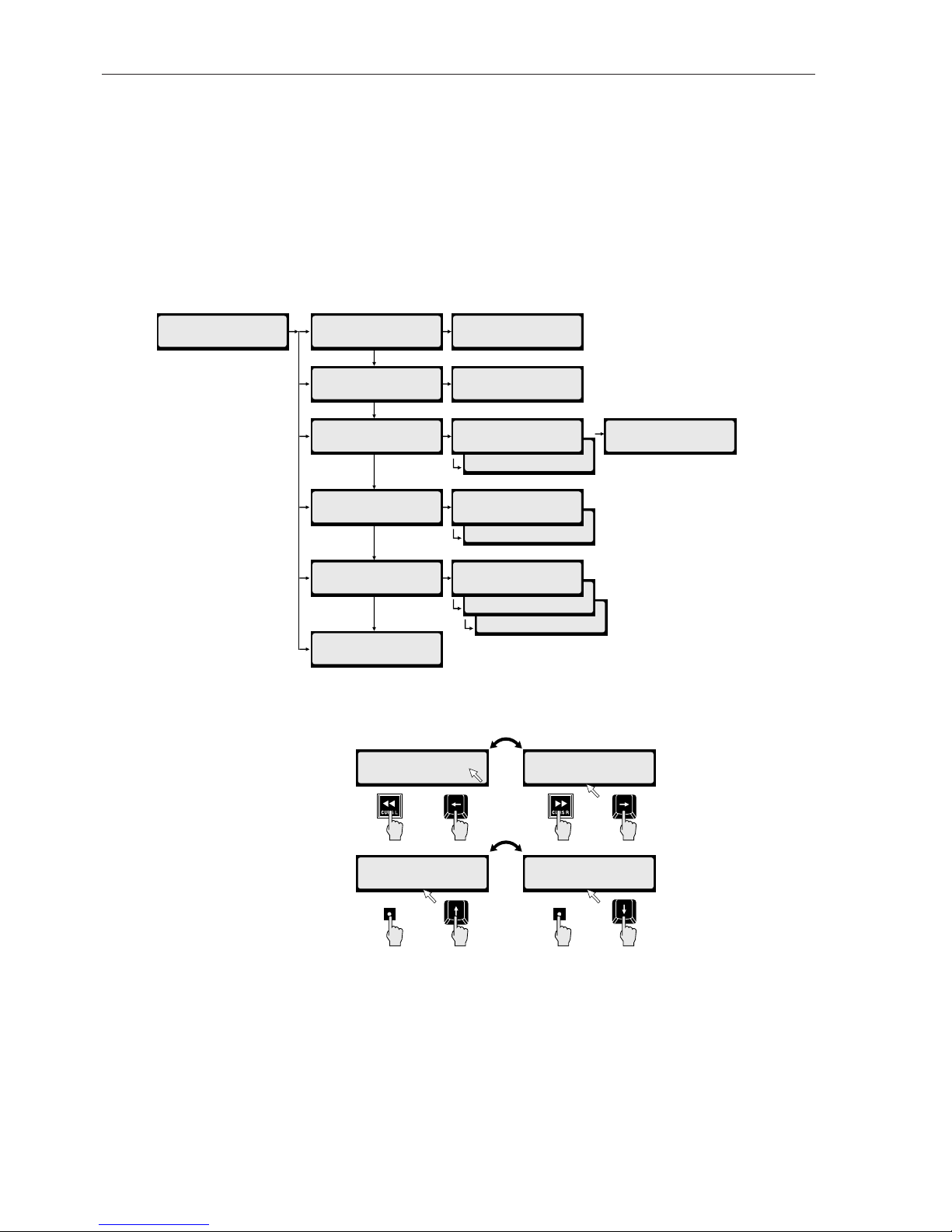
4.2.5 Scrolling and Selecting Within the Menu
1. After entering the menu as above, press UP/DOWN to move the
flashing cursor up or down vertically through the sub-menu options.
2. Press ENTER (RE-8) or STOP/ENTER (front panel) once you have
reached the submenu you want.The LCD will present the next submenu.
Once you have reached the editing dialog you require, use the cursor left or
cursor right key to move the cursor to another field.
The following diagram provides an example of the LCD menu operation—in
this case, these are the submenu items under the System menu:
Moving the Cursor inside Menu Dialogs: This diagram shows how to move
the cursor and change values in a menu dialog.
4.2.6 Editing Values in a Dialog Window
Press UP/DOWN to raise or lower a numerical value or to cycle through text
options in the field above the cursor.
Press ENTER (RE-8) or STOP/ENTER (front panel) to accept the value you
have chosen and proceed to the next dialog window.
V-SPEED: +00.00%
UNITS: PERCENT
_
V-SPEED: +00.00%
UNITS: PERCENT
_
V-SPEED: +0000c
UNITS: CENTS
_
V-SPEED: +00.00%
UNITS: PERCENT
_
Front Panel
Front Panel
Front Panel
Front Panel
RE-8
RE-8
RE-8
RE-8
UP/
YES
DOWN/
NO
CONFIGURE DISKS:
EXTERNAL
CONFIGURE DISKS:
INT+EXT
SYNC OUTPUT:
ECHO THRU
_
DIG I/O FORMAT
ADATLINK
_
MAIN MENU:
SYSTEM MENU
MAIN/SYS MENU:
SHOW DISK SPACE
_
MAIN/SYS MENU:
DIGITAL I/O
_
MAIN/SYS MENU:
SYNC OUTPUT
_
MAIN/SYS MENU:
CONFIGURE DISKS
_
MAIN/SYS MENU:
UPGRADE SYSTEM
_
RECORD TIME LEFT
A012 B023 C004
DIG I/O FORMAT:
AES/EBU, S/PDIF
_
SYNC OUTPUT:
WORDCLK
_
CONFIGURE DISKS:
INTERNAL
DIG IN L:11 R:12
OUT L:11 R:12
MAIN/SYS MENU:
SYSTEM VERSION
_
RADAR OPERATING
SYSTEM VER: 1.xx
Edition 2 (Printed in Japan)
4-6 SECTION 4
Page 71

4.3 A TOUR OF THE MENU...
This “tour” goes through each menu item, and provides a brief description. If
the item is described elsewhere in the manual, a paragraph reference is provided.
4.3.1 System Menu
4.3.1.1 System Version
Select this item to display the system software version on RADAR.
RADAR OPERATING
SYSTEM VER: 1.XX
4.3.1.2 Digital I/O
This menu item allows you to select the active digital I/O parameters—
including patched RADAR track and format.
DIG I/O FORMAT: DIG I/O FORMAT:
A
ES/EBU, S/PDIF ADATLINK
Complete digital I/O instructions are provided in §3.17.
4.3.1.3 Sync Output
This feature enables the wordclock routing feature—if set to WORDCLOCK,
the wordclock output comes from RADAR’s internal clock. If set to ECHO
THRU, the wordclock input is routed to the wordclock output.These features
are further described in Section 5.
SYNC OUTPUT: SYNC OUTPUT:
W
ORDCLOCK ECHO THRU
4.3.1.4 Configure Disks
This item establishes the system disk configuration. Four selections are
provided:
CONFIGURE DISKS: CONFIGURE DISKS:
INTERNAL INT+EXT
CONFIGURE DISKS: CONFIGURE DISKS:
EXTERNAL MONDO-8
• INTERNAL (System Default): RADAR uses internal SCSI disks (ID 0, 1, 2).
• INT+EXT: RADAR uses both internal (0,1,2) and external (3, 4, 5) disks.
• EXTERNAL: RADAR uses external SCSI disks (ID 3, 4, 5); as installed in
EBD-3.
• MONDO-8: Mondo-8 reconfigures RADAR’s disks so that all disks are used
for just tracks 1 through 8—tripling the available contiguous space on those
disks.
After changing configurations, you must create a new (blank) project before
operating, since projects do not support mixed modes. Additional information
about disk configuration appears in Appendix B, Maintenance.
RADAR MENU OPERATION 4-7
Edition 2 (Printed in Japan)
Page 72

4.3.1.5 Set Time & Date
This menu item enables you to set the time and date on RADAR’s internal
clock. This date/time information is used for time stamping backup tapes, etc.
Upon selecting this menu item, the system will respond with:
DATE:1994-Oct-20
TIME: 12:25:11
Use the cursor up/down keys to change the value of each field; use the cursor
left/right keys to move between fields and between lines. (You may also use the
jog wheel to increase/decrease field values.) When completed, press ENTER.
4.3.1.6 Upgrade System
This item enters a mode which saves the current system state, then prepares the
system for shutdown prior to installing factory-supplied software updates from
disk.
SYSTEM UPGRADE
PROCEED? N
O
Complete instructions for this menu item appear in Appendix A.
4.3.2 Project Menu
The Project menu contains the following submenus, defined below:
BACKUP MENU
RESTORE MENU
GOTO PROJECT
CREATE PROJECT
NAME PROJECT
COPY PROJECT
DELETE PROJECT
SAMPLE RATE
START TIME
SYNC OFFSET
RECLAIM SPACE
RENUMBER LOCATES
ERASE ALL DISKS
4.3.2.1 Backup Menu/Restore Menu
These items enter RADAR’s Backup and Restore modes, as described in Section
8 of this manual.
MAIN/PROJ MENU: MAIN/PROJ MENU:
B
ACKUP MENU RESTORE MENU
4.3.2.2 GOTO Project
This item enables changing the currently active project:
PROJ: 04 94Oct21
COASTER SESS
GOTO Project is described in §2.10.3.
Edition 2 (Printed in Japan)
4-8 SECTION 4
Page 73

4.3.2.3 Create Project
This item is used to create a new RADAR project:
CREATE PROJ: 06
U
NTITLED
Create Project is described in §2.10.2.
4.3.2.4 Name Project
This item is used to re-name a RADAR project, and is described in §2.10.4.
NAME PROJ: 04
COASTER2
4.3.2.5 Copy Project
This item is used to copy (or duplicate) an entire RADAR project into a new
project number. This feature is described in §2.10.5.
COPY: 04 TO 06
COASTER2 V3
4.3.2.6 Delete Project
This item deletes the current RADAR project, and is described in §2.10.8.
DELETE PROJ: 04
COASTER2 V3
4.3.2.7 Sample Rate
This item sets the project sampling rate to one of RADAR’s standard rates. This
item is described in §2.10.7, and in Section 3.
SAMPLE RATE:
48 KHz
4.3.2.8 Start Time
Start Time enables you to set a default start time for a project; this time is used
as locate point 0, and the project is automatically located to this point upon
opening.
START TIME:
00:00:00
:00.00
4.3.2.9 Sync Offset
Sync Offset allows the operator to enter a fixed offset between incoming time
code and displayed time code; this can compensate for the lag induced between
the video head and address track head on a VTR, can correct a difference
between screen burn-in and the actual time code stripe on a video tape, etc.
SET SYNC OFFSET:
00:00:00
:00.00+
This feature is described in Section 5.
RADAR MENU OPERATION 4-9
Edition 2 (Printed in Japan)
Page 74

4.3.2.10 Reclaim Space
This item reclaims unused audio from deleted projects, and is described in
§2.6.9.
RECLAIM SPACE?
N
O YES
4.3.2.11 Renumber Locates
Renumber Locates allows the operator to renumber locate points from the
beginning of a project (in time code order), starting from 1.
RENUMBER ALL?
N
O YES
4.3.2.12 Erase All Disks
This item erases all audio and all projects from RADAR. Use this item if you
have backed up your disks and want to return to a “fresh” system with the full
amount of recording time.
ERASE ALL DISKS?
N
O YES
Please Note: As this operation is not recoverable, be very sure you have all
important data backed up before proceeding.
Before RADAR erases all disks, there several warnings, as shown:
LOSE ALL AUDIO?
N
O YES
And (finally...):
ARE YOU SURE?
N
O YES
Edition 2 (Printed in Japan)
4-10 SECTION 4
Page 75

4.3.3 Edit Menu
The Edit menu contains items as shown. These items are described below:
UNDO / REDO
MODIFY EDIT
CUT
COPY
PASTE
MOVE
ERASE
LOOP
SLIDE
REVERSE
LISTEN
MUTE TRACKS
IMPORT *.WAV
CROSSFADE TIME
RECORD SAFE
4.3.3.1 Undo/Redo
This item undoes/redoes the previous RADAR operation or edit. Please note
that there are several functions, such as Erase All Disks, that cannot be recovered
using Undo!
UNDO PASTE?
N
O YES
4.3.3.2 Modify Edit
This item may be used to modify the parameters (In time, Out time, paste
point, etc.) of the previous edit. This feature is described in §7.11.
4.3.3.3 Edit Features
(Cut/Copy/Paste/Move/Erase/Loop/Slide/Reverse)
These features are described in Section 7, RADAR Editing Features.
4.3.3.4 Listen
The Listen function plays the clip currently on RADAR’s clipboard. This feature
is described in §7.2.
4.3.3.5 Mute Tracks
Mute Tracks is used to temporarily turn off disk tracks that are not in use.
Unlike a monitor mute, which only turns off the track monitoring, Mute Tracks
actually shuts off the track at the disk drive. This effectively increases the disk
drive’s available bandwidth.
Mute Tracks is most used for ensuring seamless punch-out monitoring during
overdubs. If you perform a punch-in/punch out recording operation, the
punch-out will be seamless (i.e. no gap—a smooth switch between input and
track monitoring), if the following condition is met:
The punch-out monitoring will be seamless if the number of “fr ee ” disk tracks
equals or exceeds the number of tracks you ar e recording on that disk unit.
Thus, if the disk activity exceeds the amount necessary for seamless punch-out
(i.e. all 8 disk tracks are in playback), but you need to overdub on just two
tracks, you may use Mute Tracks to turn off two other tracks on the disk,
freeing the bandwidth to enable the seamless punch-out monitoring.
Complete operating instructions for this feature appear in §7.13.
RADAR MENU OPERATION 4-11
Edition 2 (Printed in Japan)
Page 76

4.3.3.6 Import *.WAV Files
This feature enables you to import any valid .WAV sound file from RADAR’s
floppy disk drive into the RADAR editing clipboard; from there the sound file
may be placed into any RADAR project.
This feature is most useful for importing sound file samples directly, without a
D/A conversion. Upon import, you may select the converted playback sample
rate (which defaults to the current sample rate) and gain for the sound file. This
feature is described in §7.14.
4.3.3.7 Crossfade Time
This item enables you to set and change the crossfade time to be used on all
edits and record punch-ins. (Crossfade time is specified in milliseconds; the
default setting is 5 milliseconds.) Minimum crossfade time is 0, maximum is
100 milliseconds.
To set or change Crossfade time, select this item, then use the up/down keys on
the front panel, or the numeric keys (or jog wheel) on the RE-8, to set the new
crossfade time. This feature is described in §7.2.
4.3.3.8 Record Safe
Record Safe enables you to globally place RADAR into Safe mode, mimicking
the function of the SAFE key on the RE-8. If the system is placed into Record
Safe, you cannot arm tracks, and the SAFE key is lit on the RE-8. To arm tracks
again, you must re-select “RECORD SAFE: OFF:” from the Edit menu, or you
must press the SAFE key on the RE-8.
RECORD SAFE:
O
N OFF
Edition 2 (Printed in Japan)
4-12 SECTION 4
Page 77

4.3.4 Preferences Menu
The Preferences menu contains the following submenus and dialogs. These
items are described below.
DEF SMPTE FIELD
SMPTE LOCK SPEED
TRACK SOLO MODE
LOW DISK WARNING
SLIDE TIME UNITS
RECORD MODE
FFWD & REW RATE
PEAK HOLD TIME
CLIP HOLD TIME
SAVE STATE DELAY
4.3.4.1 Default SMPTE Field
This item allows you to select on which field the LCD cursor is flashing when a
timecode number is displayed for editing. (You may always move the cursor
after the timecode number is displayed—however, having the cursor placed on
the most-used field saves keystrokes.)
DEF SMPTE FIELD:
S
ECONDS FRAMES
The available choices are seconds or frames. Make your selection using the
cursor left/right keys, then press ENTER.
4.3.4.2 SMPTE Lock Speed
This item allows you to select the behavior of RADAR’s SMPTE timecode lock.
A setting of Fast allows for fast, accurate tracking of the incoming SMPTE
timecode. A setting of Slow allows for smoother tracking, especially of jittery
timecode sources—this is at the expense of longer timecode lock time.
SMPTE LOCK SPEED:
F
AST SLOW
Make your selection using the cursor left/right keys, then press ENTER.
4.3.4.3 Track Solo Mode
Track Solo is a playback monitoring feature using the RE-8. Three Track Solo
mode settings are available:
SOLO MODE: SOLO MODE: SOLO MODE:
A
DDITIVE INTERLOCK MOMENTARY
• Additive: In Additive Solo mode, each time a track solo key is pressed, the
track is “added” to any others being soloed.
• Interlock: In Interlock Solo mode (the system default), every time a solo key
is pressed, the previous soloed track(s) are taken out of Solo.
If you want to solo more than one track while in Interlock Solo mode, simply
press and hold the first track solo key, then select additional tracks to be
soloed.
• Momentary: In Momentary Solo mode, track(s) are kept in solo for as long as
their solo keys are held.
RADAR MENU OPERATION 4-13
Edition 2 (Printed in Japan)
Page 78

4.3.4.4 Low Disk Warning
This item allows you to set a low-disk space alarm, so that if available recording
time gets below the specified amount, RADAR posts a warning on the LCD.
LOW DISK LEVEL
WARNING: 05 MIN
The default setting for this level is 5 minutes; you may change this as desired
between 99 minutes and 0 minutes.
Please Note: To receive no low disk space warning, set the level to 0 minutes.
4.3.4.5 Slide Time Units
This menu item enables you to specify the type of units used when the Slide
Edit feature is used.
SLIDE TIME UNITS
F
RAMES MSECS
The choices are frames or milliseconds; make your selection with the cursor
keys, then press ENTER,
4.3.4.6 Record Mode
The Record Mode menu item enables you to set two important preferences:
• Record Key Combination
• Punching Additional Tracks Behavior
When the Record Mode menu item is selected, the system will respond with:
RECORD:REC+PLAY RECORD:REC
A
RM TK:REC READY ARM TK:INST REC
Use the cursor left/right keys to switch between the RECORD and ARM TK
fields, and use the cursor up/down keys within the fields to change the settings.
These submenu dialogs operate as follows:
• RECORD (Record Key Combination): The RECORD submenu provides
two choices for how RADAR is placed into record: REC plus PLAY, or REC
only. Make your selection as desired, then press ENTER to return to Ready
mode. (Or, press the cursor right key to change to the ARM TK: field, below.)
• ARM TK (Punching Additional Tracks Behavior): Use the ARM TK: item
to select how RADAR behaves during a recording when additional tracks are
armed for record. Two choices are provided: REC READY and INST REC
(“Instant Record”).
REC READY, the systems default setting, additional tracks may be armed for
record while other tracks are already in record; to begin recording on the
newly-armed tracks, you must enter Record again.
If, however, INST REC (instant record) is selected, the act of arming an
additional track places that track immediately into record, with no additional
keystrokes.
Make your selecting using the cursor up/down keys, then press ENTER to
return to Ready mode, or press the cursor left key to return to the RECORD:
submenu.
Edition 2 (Printed in Japan)
4-14 SECTION 4
Page 79

4.3.4.7 Fast Forward/Rewind Rate
Use this item to select the speed of fast-wind when either the FFWD or REW
keys are pressed. (The range is from 1x to 99x play speed.) Make your selection
using the cursor up/down keys, the numeric keypad, or the jog wheel; then
press ENTER.
FFWD & REW RATE:
10
TIMES NORMAL
Please Note: RADAR provides two fast wind speeds—the standard speed as set
on this menu, and a faster speed obtainable when the FF or REW key is pressed
twice in a row. The double-press speed is 3x faster than the regular speed.
4.3.4.8 Peak Hold Time (Input/Playback Metering)
This menu item enables you to set how long RADAR’s meters will hold a peak
level indication. This duration is specified in seconds, with a top limit of 999
seconds:
PEAK HOLD TIME:
001 SECONDS
Make your selection using the cursor up/down keys, the numeric keypad, or the
jog wheel; press ENTER to return to Ready mode.
Please Note: To hold level peaks indefinitely, enter “-1” for this setting. To
disable the feature, enter “0”.
4.3.4.9 Clip Hold Time (Input/Playback Metering)
This menu item enables you to set how long RADAR’s meters will display a clip
level indication after a digital clip on input or playback. This duration is
specified in seconds, with a top limit of 999 seconds.
CLIP HOLD TIME:
-01 SECONDS
Make your selection using the cursor up/down keys, the numeric keypad, or the
jog wheel; press ENTER to return to Ready mode.
Please Note: To hold level clips indefinitely, enter “-1” for this setting. To
disable the feature, enter “0”.
4.3.4.10 Save State Delay
This item enables you to specify how long after your last system action RADAR
waits before it performs its periodic “Saving State” operation. This delay is set
in seconds, as shown:
SAVE STATE DELAY
15
SECONDS
Save State Delay is specified in seconds from 1 to 99. Make your selection using
the numeric keys or jog wheel, then press ENTER.
Please Note: The Save State feature cannot be shut off indefinitely.
RADAR MENU OPERATION 4-15
Edition 2 (Printed in Japan)
Page 80

4.3.5 Diagnostics Menu
This menu provides a variety of diagnostics for RADAR, its SCSI bus, SCSI
devices, and display diagnostics. The Diagnostics menu hierarchy is shown
below.
Please Note: The Diagnostics features on this menu are described in Appendix
B, Maintenance. For your convenience, a brief description of each item is
provided here.
SCAN SCSI BUS
MOUNT / UNMOUNT
INIT DISK
CHECK DISK
REPAIR DISK
SHOW FREE RAM
DIS_PLAY TEST 1
DIS_PLAY TEST 2
CONFIGURE DEBUG
SHOW DEBUG
SAVE DEBUG
PLAYLIST ERRORS
REALTIME ERRORS
4.3.5.1 Scan SCSI Bus
This item scans RADAR’s SCSI bus for SCSI devices, then posts them to the
LCD, where you may scroll through them to read device names and SCSI ID
numbers.
4.3.5.2 Mount / Unmount
This item mounts and unmounts RADAR’s file system—this function should
only be used under the direction of Otari Technical Support!
4.3.5.3 Disk Diagnostics (INIT DISK/CHECK DISK/REPAIR DISK)
These menu items are used when diagnosing and repairing SCSI disk problems.
CAUTION!
INIT DISK IS DESTRUCTIVE TO BOTH THE AUDIO DATA ON THE
DISK AND THE FILE SYSTEM—THEREFORE IT SHOULD ONLY BE
USED UNDER DIRECTION OF OTARI TECHNICAL SUPPORT!
4.3.5.4 Show Free RAM
This menu item displays the amount of free RAM available on RADAR; this
information may be helpful to Otari Technical Support when troubleshooting.
4.3.5.5 Debug/Error Logging
RADAR software contains extensive error logging features, including a “Debug”
mode that records and captures real-time problems for storage on a floppy disk,
as well as two project error logging mode:
PLAYLIST ERRORS
REALTIME ERRORS
Information from these modes may be useful to Otari Technical Support when
troubleshooting. These features are described in Appendix B.
Edition 2 (Printed in Japan)
4-16 SECTION 4
Page 81

4.3.6 Shutdown RADAR
This item saves the current RADAR state, and enables safe, trouble-free powerdown. After you select this item, the system will prompt you for confirmation
via the LCD, then will say:
YOU MAY SAFELY
TURN OFF POWER
Please Note: After the SHUTDOWN RADAR item is selected, RADAR
cannot be operated again until the system power is turned off then back on
again!
RADAR MENU OPERATION 4-17
Edition 2 (Printed in Japan)
Page 82

Page 83

Edition 2 (Printed in Japan)
This section describes RADAR’s external synchronization features, including
SMPTE timecode sync, external house sync, and digital word clock sync
features.
This section includes the following subsections.
5.1 GENERAL
...................................................5-2
5.1.1 Synchronization Overview ...........................5-2
5.1.2 SMPTE Overview ...................................5-2
5.1.2.1 SMPTE Frame Rates..............................5-3
5.1.2.2 Chasing a Variable Speed Timecode Source .........5-3
5.1.2.3 Recording to Timecode ...........................5-3
5.1.3 MIDI Timecode Sync Overview.......................5-4
5.1.4 Video Reference (House Sync) Overview ..............5-4
5.1.5 External Word Clock Overview ......................5-4
5.2 EXTERNAL SYNC CONNECTIONS ...........................5-5
5.2.1 Timecode Connections ..............................5-5
5.2.1.1 Timecode Input..................................5-5
5.2.1.2 Timecode Generator Output.......................5-5
5.2.2 MIDI Timecode (MTC) Connections...................5-5
5.2.3 Video Sync Connections.............................5-5
5.2.4 Digital Wordclock Connections ......................5-5
5.3 SMPTE TIMECODE OPERATION ..............................5-6
5.3.1 Setup for Timecode Operations.......................5-6
5.3.2 Recording While Locked to Timecode.................5-7
5.3.3 Playback to Timecode ...............................5-7
5.3.4 SMPTE Offset.......................................5-7
5.4 EXTERNAL SYNC (HOUSE SYNC) OPERATION ................5-8
5.5 DIGITAL WORDCLOCK OPERATION ..........................5-9
Section 5 External Synchronization Features
Page 84

5.1 GENERAL
RADAR provides power external sync features as standard equipment, making
RADAR equally suited for large-format multitrack recording operation, video
post production, and video-reference locked digital audio operation. This
section describes the following RADAR features:
SMPTE Timecode Chase Lock
SMPTE Timecode Generator
External Video (House) Sync Operation
External Digital Word Clock Operation
5.1.1 Synchronization Overview
Synchronization is the process of making two things happen at the same time.
An example in music production would be making a bass drum and bass guitar
note happen at the same time. In film/video production work, synchronization
is used to ensure that the sound of the car door slam and the visual of the door
closing occur at exactly the same time. In our case Sync is used to make sure
RADAR records and plays back perfectly in time with the various video and
audio machines used in these environments.
Sync can also be used to expand the number of tracks available for recording.
There may be times when you have more instruments than RADAR has tracks
and you want to chain another multitrack machine to RADAR to augment your
tracks. When you physically record tracks in two separate machines, sync makes
it appear as though they are located on one large multitrack machine.
The relationship in a synchronized multi-machine setup is that of master and
slave. The master machine dictates where the slaves should cue to and play
from. The master also provides the ongoing timing information that keeps
playback tracks on all synchronized machines together over time.
5.1.2 SMPTE Overview
SMPTE timecode is measured in terms of hours, minutes, seconds, frames (24
to 30 frames per second) and, in the case of RADAR, subframes which is one
hundredth of one frame. There are a number of different frame rates that
correspond to motion picture film, black and white video, color video, and the
frequency of AC power mains in different parts of the world. RADAR is capable
of synchronizing to all frame rates in use world wide.
SMPTE timecode is an audio signal, although the signal encodes an 80 bit
digital word containing precise positioning information. This allows the device
reading the timecode to accurately determine the position of the matching
audio or video.
Normally, timecode is recorded onto one track of tape or video sources intended
to be used in a master/slave control relationship. When the master source tape is
put into play, any machines (slaves) will read the SMPTE signal and “chase” it,
meaning they will start playback and continue playing in sync with the master
source.
Edition 2 (Printed in Japan)
5-2 SECTION 5
Page 85

5.1.2.1 SMPTE Frame Rates
The frame rates of SMPTE timecode used throughout the world are 30 frames
per second (fps), 29.97 fps, 25 fps, or 24 fps. In addition, the 30 and 29.97 fps
rates also have drop-frame variants to compensate for the slight synchronization
delay introduced by the NTSC broadcast television standard. (Detailed
information about the various frame rates is beyond the scope of this manual,
and appears in any text on timecode.)
Generally, 24 fps is used in film applications, 25 fps is used for PAL standard
video, and 30 fps is used for audio and some NTSC video.
The 29.97 fps rate corresponds to the actual frame rate of the NTSC color
video signal. (When television in North America was monochrome, the frame
rate was 30 fps. The introduction of color television required that chrominance
be encoded along with the luminance of B&W television. This compromise
allowed older, B&W televisions to receive the same signals as the new color sets;
however the frame rate was lowered to 29.97 frames per second.)
Drop Frame was introduced as a means of compensating for the difference
between 29.97 and 30 frames per second over the broadcast day. Over the
course of an hour, the difference between the old B&W and new color rates was
about 3 seconds and 20 frames; over a day the difference was about a minute
and a half.
In the drop frame scheme, two frames are “dropped” every minute (i.e.
00:00:59:29f jumps to 00:01:00:02f, dropping frames 00 and 01). To make the
math work out, the “tens” minutes do not drop frames.
In North America, almost all broadcast video uses 29.97/drop frame timecode.
Since this is not a universal rule, it’s always important to check the frame rate
before you start—since it is very difficult to change frame rates part way
through a job!
5.1.2.2 Chasing a Variable-Speed Timecode Source
If the master timecode is coming from a tape-based machine, its rate may
fluctuate as the playback speed increases and decreases due to tape inaccuracies.
If the slave device does not respond to these fluctuations, master and slave will
eventually become noticeably out of sync.
However, as a true timecode slave, RADAR continually checks the incoming
SMPTE code and modulates its internal sample rate accordingly. This ensures
that RADAR stays locked in perfect sync for the duration of the program
material.
5.1.2.3 Recording to Timecode
RADAR can chase timecode while recording, and due to its advanced timecode
features, can even track an unstable tape-based timecode source while recording,
while maintaining timecode lock! Recording to timecode operates exactly like
normal recording, however RADARmust be set up to chase the correct
timecode format.
EXTERNAL SYNCHRONIZATION FEATURES 5-3
Edition 2 (Printed in Japan)
Page 86

5.1.3 MIDI Timecode Sync Overview
The MIDI specification includes a timecode scheme not unlike SMPTE. Both
timecode varieties use hours/minutes/seconds/frames; however the SMPTE
variant also provides separate even and odd fields for each frame. (Another
difference is that MTC is carried on RADAR’s MIDI ports, while SMPTE is
carried on the LTC jacks.)
Thiis feature is not yet implemented.
5.1.4 Video Reference (House Sync) Overview
In video production/post production facilities, a high-quality, stable video signal
must be maintained at all times. Since the stability of a video signal involves
accurate timing of sync pulses and vertical blanking intervals, all equipment
used in video production houses must be locked to a master, facility-wide clock
signal. This clock signal enables RADAR to maintain a stable lock to any time
code generated in the facility. And, when using RADAR in conjunction with
high-end video equipment (such as D2 and Digital Betacam), RADAR’s house
sync capability enables flawless digital audio transfers while locked to timecode.
5.1.5 External Word Clock Overview
RADAR’s digital audio hardware generates a stable digital word clock, used to
synchronize digital data transfer over the AES/EBU or S/PDIF ports.
Sometimes, it is necessary to use an external word clock, such as the one
generated by a digital betacam machine, during digital audio transfers. An
example of this is during digital audio “layback” to a video machine—its digital
video synchronization (and its own internal digital word clock) has been derived
from the house sync source, and to avoid any digital signal delay when
transferring audio from RADAR back to the video deck, it generates a word
clock. RADAR locks to this word clock, and transfers the audio accurately.
Edition 2 (Printed in Japan)
5-4 SECTION 5
Page 87

5.2 EXTERNAL SYNC CONNECTIONS
5.2.1 Timecode Connections
5.2.1.1 Timecode Input
RADAR accepts LTC on a 1/4" phone plug. This signal may be balanced or
unbalanced. (Input Level: 100 mV to 2.5 V p-p)
• Connect the timecode source to RADAR’s SMPTE IN jack.
5.2.1.2 Timecode Generator Output
RADAR’s internal SMPTE generator may be used as a master source for slaving
other devices. (Output Level: 1V p-p balanced., 0.5V p-p unbalanced)
• Connect a 1/4" phone plug (balanced or unbalanced) to RADAR’s
SMPTE OUT jack.
The timecode generator output is always active, even if the transport is
stationary.
5.2.2 MIDI Timecode (MTC) Connections
MIDI timecode (MTC) is a sync protocol used by samplers and MIDI control
equipment. This feature is not yet implemented.
5.2.3 Video Sync Connections
If using Video Sync (house sync), connect the sync source to the SYNC
REFERENCE IN BNC connector on RADAR’s rear panel.
The SYNC REFERENCE OUT connector provides a hard-wired loop through;
you may connect this output to other device(s) requiring the same sync source.
Please Note: If the video source requires ground termination, a 75Ω
termination resistor may be inserted using the switch between the SYNC
REFERENCE IN and OUT connectors. Generally, termination is required if
RADAR is the last device (or only device) in the sync chain, and if there is no
downstream device connected to SYNC REFERENCE OUT.
Do not insert the termination resistor if loop through is configured, and any
device is connected to SYNC REFERENCE OUT!
5.2.4 Digital Word Clock Connections
If using RADAR with an external digital word clock source, connect this source
to the SYNC REFERENCE IN connector. If a loop-through is required, you
may connect the SYNC REFERENCE OUT connector to the device requiring
the same digital word clock.
Please refer to the above note regarding termination for digital word clock.
OUTIN
AES/EBU
OUTIN
S/PDIF
OUTIN
LTC
SMPTE/EBU
MIDI PC KBD
OUTTHRU IN IN
EXTERNAL SYNCHRONIZATION FEATURES 5-5
Edition 2 (Printed in Japan)
Page 88
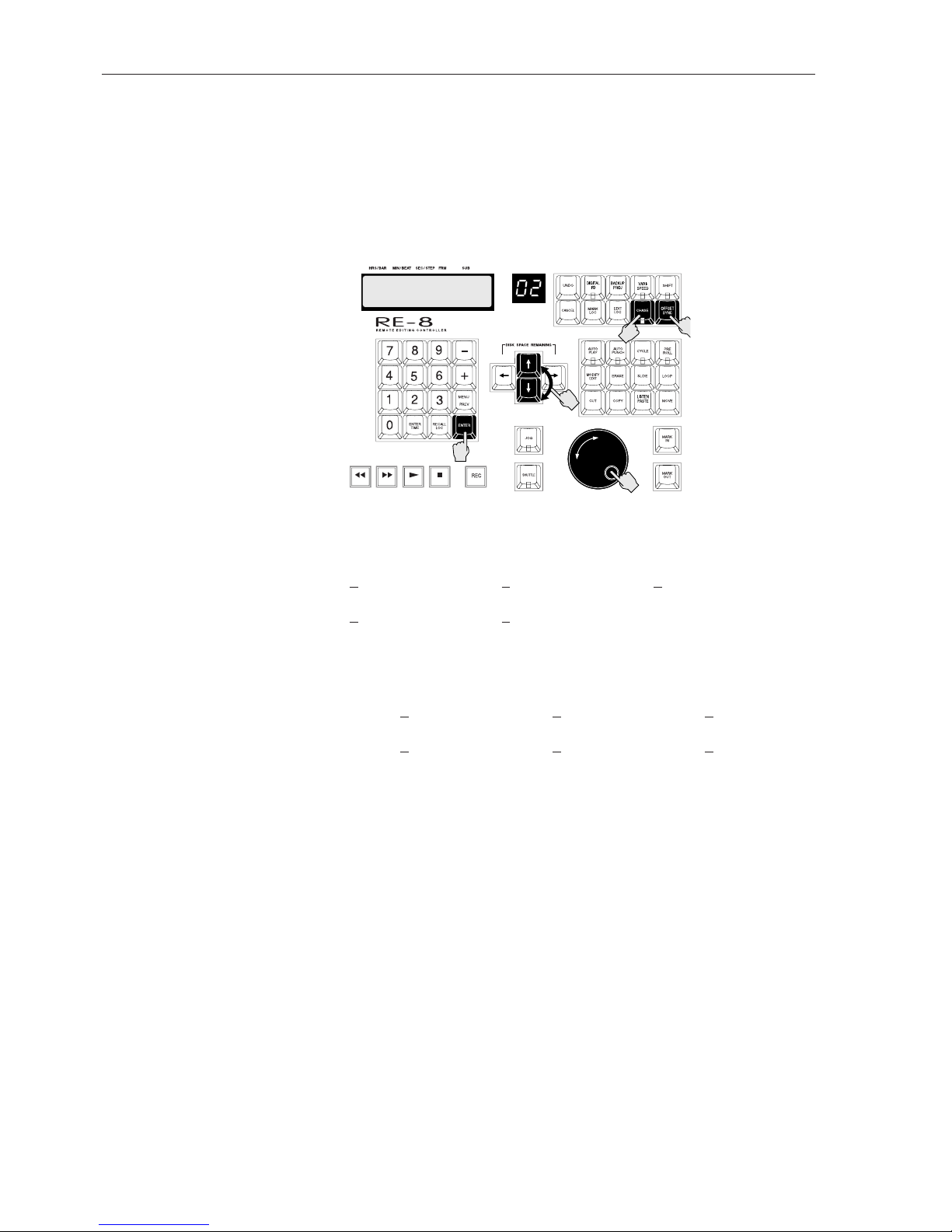
5.3 SMPTE/MIDI TIMECODE OPERATION
5.3.1 Setup for Timecode Operation
Before timecode operation, you must select the frame rate to be used. This setup
is available as follows:
From the RE-8:
1. Press SYNC/OFFSET. The system will display:
The system will respond with the Sync Source dialog; there are a number of
possible selections, as shown below:
SYNC SOURCE: SYNC SOURCE: SYNC SOURCE:
S
MPTE MIDI DIGITAL
SYNC SOURCE: SYNC SOURCE:
V
IDEO WORDCLOCK
2. Use the cursor up/down keys to select SMPTE (or MIDI), then press
ENTER. The LCD will then present the Format dialog:
CONFIGURE SYNC: CONFIGURE SYNC: CONFIGURE SYNC:
RATE: 3
0 RATE: 30 DROP RATE: 29.97 DROP
CONFIGURE SYNC: CONFIGURE SYNC: CONFIGURE SYNC:
RATE: 2
9.97 RATE: 25 RATE: 24
3. Use the up/down keys (or the jog wheel) to select a rate from one of the
provided options, then press ENTER.
4. Press CHASE to enable RADAR to chase lock to incoming timecode.
Press again to disable. The CHASE LED will blink indicating that
RADAR is waiting for timecode. When timecode is received, this LED will
glow solid.
From the Front Panel: Front panel operation is virtually identical to the above
RE-8 description except for these minor differences:
• You must press EXT SYNC to enter the Configure Sync menu.
• The STOP/ENTER key is used in place of ENTER.
• When you have completed all of the edit dialogs and have returned to Ready
mode, RADAR will have automatically entered Chase mode.
Chase Enable/Disable from Front Panel: To disable Chase mode from the
front panel, press EXT SYNC twice. To re-enable, press EXT SYNC twice
again.
SYNC SOURCE:
SYMPTE
2,3
2,3
2,4
5
1
Edition 2 (Printed in Japan)
5-6 SECTION 5
Page 89

5.3.2 Recording while Locked to Timecode
To maintain sync to a timecode master on playback, you must record the
material while chasing the timecode source. To record while chasing timecode:
1. Press CHASE (RE-8) or EXT SYNC (front panel) to enable timecode
chase.
2. Start the timecode source. RADAR begins to chase in a second or so.
3. Enter Record using the transport keys. (Record to timecode functions
exactly like standard recording; this is described in §3.5.)
4. Press PLAY or STOP to leave record, or stop the timecode source.
5.3.3 Playback to Timecode
Playback to timecode requires that you select the timecode format (SMPTE or
MIDI) and rate (24–30 fps). Then, simply supply the timecode to RADAR’s
SMPTE IN (or MIDI IN) jack; RADAR cues automatically, and will begin to
play locked to the incoming timecode.
5.3.4 SMPTE Offset
Offset is used when there is audio beginning at one SMPTE location already
recorded on RADAR and audio beginning at another SMPTE time on another
machine and they both must play together. RADAR allows you to vary the
offset, that is, the difference in hours, minutes, seconds, frames and subframes
between its internal SMPTE time and the sync master. Offset may be edited
while both machines are running in sync. Normally, the default offset is
00:00:00:00:00 but this can be changed when necessary. If you already know
the exact Offset time, this can be entered directly in the Set dialog.
Setting SMPTE Offset from the RE-8:
1. Press SHIFT, release it and then press SYNC/OFFSET. The LCD will
present the Set Sync Offset dialog:
SET SYNC OFFSET
00:00:00:00.00+
2. Enter the offset time from right to left starting with frames. Or, use the
jog wheel to dial in the desired value(s). Use the + and - keys to make the
offset positive or negative.
3. Press ENTER to return to Ready mode.
From the Front Panel: This is essentially identical except for the procedure in
which you enter the initial Offset dialog:
1. Press and release MENU/ESC.
2. Use <</CURS L and >>/CURS R to scroll through the submenu
options until the flashing cursor rests beneath the Project submenu.
3. Press STOP/ENTER.
4. Press DOWN/NO several times to scroll to the Set Sync Offset
submenu and then press STOP/ENTER.
Repeat the steps described above.
EXTERNAL SYNCHRONIZATION FEATURES 5-7
Edition 2 (Printed in Japan)
Page 90

5.4 EXTERNAL SYNC (VIDEO REFERENCE) OPERATION
External Sync Overview: In video production/post production facilities, a
high-quality, stable video signal must be maintained throughout the production
cycle. Since the stability of a video signal involves accurate timing of sync pulses
and vertical blanking intervals, all equipment used in video production houses
must be locked to a master, facility-wide clock signal. This clock signal is
variously called “Video Reference”, “House Sync,” “Black Burst,” or “RS-170.”
(While the nature of these signals vary slightly depending on the needs of the
facility, the basic function is the same as far as RADAR is concerned.)
House Sync enables RADAR to maintain a stable lock to any time code
generated in the facility. And, when using RADAR in conjunction with highend video equipment (such as D2 and Digital Betacam), RADAR’s house sync
capability enables flawless digital audio transfers while locked to time code.
Positional Sync: Video reference provides RADAR with a synchronization
signal only—and does not contain time code information. Therefore, RADAR’s
video reference feature enables you to select the source for “positional”
sync—this could be SMPTE timecode, MIDI timecode (MTC) or RADAR’s
internal clock. In the case of SMPTE or MIDI timecode, the sync timing comes
from the incoming video reference, while the position information comes from
the incoming timecode.
Video Reference Operation:
1. From the front panel, press EXT SYNC (or, on the RE-8, press
OFFSET/SYNC). The system will respond with the Sync Source dialog
described earlier.
2. Using the cursor up/down keys (or jog wheel), select VIDEO:
SYNC SOURCE:
V
IDEO
3. Press ENTER. The system will respond with the Video Reference (sync
rate) dialog, as shown. This dialog has three choices—NTSC at 59.94 fps,
NTSC at 60 fps, or PAL at 50 fps.
VIDEO REFERENCE: VIDEO REFERENCE: VIDEO REFERENCE:
N
TSC 59.94 NTSC 60 PAL 50
4. Select the desired video reference sync rate, then press ENTER. The
system will respond with a Positional Source selection:
POSITIONAL SRC: POSITIONAL SRC: POSITIONAL SRC:
I
NTERNAL SMPTE MIDI
5. Select the desired positional source, then press ENTER. Remember that
video reference provides timing information only (i.e. when!), but the
positional source provides the place (i.e. where!)
If you selected INTERNAL, the system returns to Ready mode.If you selected
either SMPTE or MIDI, you must now specify an expected frame rate for
the timecode. In these cases the system responds with:
CONFIGURE SYNC: CONFIGURE SYNC: CONFIGURE SYNC:
RATE: 3
0 RATE: 30 DROP RATE: 29.97 DROP
CONFIGURE SYNC: CONFIGURE SYNC: CONFIGURE SYNC:
RATE: 2
9.97 RATE: 25 RATE: 24
Edition 2 (Printed in Japan)
5-8 SECTION 5
Page 91

6. Use the jog wheel or the cursor keys to select the desired frame rate,
then press ENTER.
If you select INTERNAL for positional source, the system will use its internal
clock. If you select SMPTE, RADAR uses the incoming timecode—if you select
MIDI, MTC from the MIDI port is used. In any of these cases, the actual
timing is derived from the incoming video sync.
5.5 DIGITAL WORD CLOCK SYNC OPERATION
Wordclock Sync Operation:
1. From the front panel, press EXT SYNC (or, on the RE-8, press
OFFSET/SYNC). The system will respond with the Sync Source dialog
described earlier.
2. Using the cursor up/down keys (or jog wheel), select WORDCLK:
SYNC SOURCE:
W
ORDCLK
3. Press ENTER. Wordclock sync is now enabled.
EXTERNAL SYNCHRONIZATION FEATURES 5-9
Edition 2 (Printed in Japan)
Page 92

Page 93

Edition 2 (Printed in Japan)
This section describes the features and functions of RADAR’s optional RE-8
session controller, including installation and basic operation.
This section includes the following subsections.
6.1 INTRODUCTION
............................................6-2
6.2 A TOUR OF THE RE-8 SESSION CONTROLLER.................6-2
6.2.1 Track Arm Keys...........................................6-2
6.2.2 Track Function Keys .......................................6-2
6.2.2.1 REC SAFE......................................6-2
6.2.2.2 TRACK SOLO...................................6-2
6.2.2.3 AUTO INPUT ...................................6-3
6.2.3 Text Entry Keys ...........................................6-3
6.2.4 LCD & Numeric Display....................................6-3
6.2.4.1 LCD...........................................6-3
6.2.4.2 2-Digit LED Display ..............................6-3
6.2.5 Calculator Keys ..........................................6-4
6.2.5.1 Numeric Keypad ................................6-4
6.2.5.2 + (Plus) and – (Minus) Keys........................6-4
6.2.5.3 MENU/PREV Key ...............................6-4
6.3.5.4 ENTER Key.....................................6-5
6.3.5.5 RECALL LOC Key................................6-5
6.3.5.6 ENTER TIME Key ................................6-5
6.2.6 Transport Keys............................................6-5
6.2.7 Cursor Keys..............................................6-5
6.2.8 Utility Keys...............................................6-6
6.2.9 RE-8 Dedicated Editing Keys................................6-7
6.2.10 Jog/Shuttle Wheel.......................................6-7
6.2.10.1 Entering Jog Mode .............................6-7
6.2.10.2 Entering Shuttle Mode...........................6-8
6.2.11 MARK IN & MARK OUT Keys .............................6-8
6.2.11.1 Defining a Location using MARK IN ...............6-8
6.2.11.2 Defining a Location using MARK OUT..............6-8
6.2.11.3 Recalling & Editing a Marked Location Point ........6-9
6.3 FOOT SWITCH FEATURES....................................6-9
Section 6 RE-8 Session Controller Features
Page 94
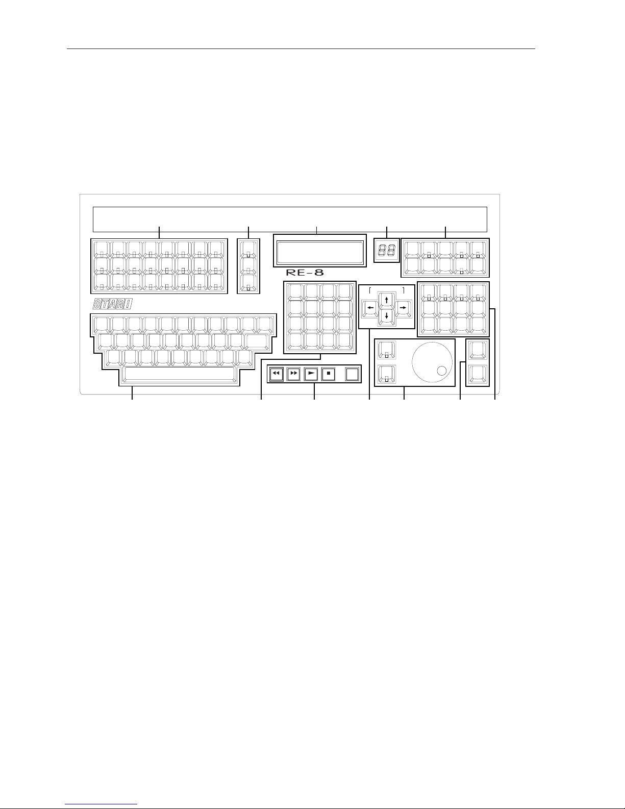
6.1 INTRODUCTION
The RE-8 session controller provides remote control of basic RADAR functions
as well as providing the necessary functions and a jog wheel for the editing of
audio data. The RE-8 also has input jacks for foot switches to allow hands-free
control of selected transport functions.
The RE-8 function keys are arranged in groups to make them easier to learn as
well as reducing unnecessary hand movements. These are explained in detail
below.
6.2 A TOUR OF THE RE-8 SESSION CONTROLLER
6.2.1 Track Arm Keys
The track arm keys are used to for several purposes: for arming tracks prior to
record, for punching in on additional tracks while recording, and in editing
modes, for selecting track(s) to be edited. These switches are momentary type
with an LED in the center to indicate active status.
6.2.2 Track Function Keys
6.2.2.1 REC SAFE/CLEAR (§3.5.4)
This function protects against accidental erasure by locking-out the track
arming keys. It can also disarm a group of tracks any time you press the REC
SAFE. SHIFT followed by this key will clear all selected tracks.
6.2.2.2 TRACK SOLO (§3.7)
This is used to audition individual or multiple tracks while muting the rest, and
is designed to be a more convenient method for solo when editing audio with
the RE-8. (TRACK SOLO is also useful as a stereo-in-place solo function if your
mixing desk is not capable of this.)
HRS/BAR MIN/ BEAT SEC/STEP FRM SUB
REMOTE EDITING CONTROLLER
DISK SPACE REMAINING
12345678
910111213141516
17 18 19 20 21 22 23 24
123
456
789
0
QWERTYU I OP
ASDFGHJKL
ZXCVBNM#&
UNDO
DIGITAL
I/O
BACKUP
PROJ
VARI-
SPEED
SHIFT
CANCEL
MARK
LOC
EDIT
LOC
CHASE
OFFSET
SYNC
AUTO
PLAY
AUTO
PUNCH
ERASE
PRE
ROLL
MODIFY
EDIT
ERASE
SLIDE
LOOP
CUT COPY
LISTEN
PASTE
MOVE
MARK
IN
MARK
OUT
JOG
SHUTTLE
REC
ENTER
TIME
RECALL
LOC
ENTER
MENU
PREV
–
+
BACK
SPACE
ENTER
REC
SAFE
TRACK
SOLO
AUTO
INPUT
00:00:00:00.00
LOC:04 CHORUS 01
TEXT ENTRY
GROUP
CALCULATOR
GROUP
TRANSPORT
CONTROLS
ARROW
GROUP
JOG
WHEEL
MARK
IN/OUT
EDITING
GROUP
UTILITY
GROUP
LED
DISPLAYLCD
TRACK FUNCTION
GROUP
TRACK ARMING
GROUP
Edition 2 (Printed in Japan)
6-2 SECTION 6
Page 95

To enable Track Solo:
1. Press TRACK SOLO. The key’s LED will flash quickly and the LCD will
prompt: Select Tracks To Solo.
2. Choose one or several tracks from the track arming group. When
selected, the track arming LEDs will blink for each soloed track. You may
now perform all transport operations except recording.
Please Note: During playback, the meters will show levels for only those tracks
soloed.
To disable Track Solo, press TRACK SOLO again. Its LED will go out and
you can resume normal operation. The tracks that were previously set in Track
Solo are remembered for the next time you engage this function.
Track Solo Modes: Three Track Solo modes (Additive, Interlock, and
Momentary) are available, as described in §3.7. The active Solo mode may be
selected on the Preferences menu.
6.2.2.3 AUTO INPUT (§3.9)
The AUTO INPUT key is used to select if existing program material on RecReadied tracks is monitored during playback (i.e. prior to punch in). When set
to Auto Input, RADAR monitors existing material on Rec-Readied tracks before
and after a Record operation. During Recor d, RADAR automatically switches
to input monitoring, and upon punch out, returns to the existing track material.
6.2.3 Text Entry Keys
The text entry area is used as a fast way to enter names for location points and
backups. This area provides the alphabet in QWERTY format; and since
naming functions on RADAR do not require them, the shift, numeric or
control keys do not appear.
The QWERTY keys may also be used as an alternativ e way to navigate through
menu fields. If you know the name of the desired menu selection, you can type
only its first letter in place of using the cursor up/down keys. The same is true
for autolocating. If you have previously named the locate points in your project,
you can press RECALL LOC, then type the first letter of the location point’s
name to recall it!
6.2.4 LCD & Numeric Display
6.2.4.1 LCD
The main RE-8 display is a large 2 line by 16 character backlit LCD. This
display offers feedback on all menu, configuration and editing functions, and
duplicates the characters on the RADAR front panel display.
6.2.4.2 2-Digit LED Display
The smaller LED display to the right of the main LCD indicates the currently
active RADAR project. More information about this feature appears in
§2.10.
RE-8 SESSION CONTROLLER FEATURES 6-3
Edition 2 (Printed in Japan)
Page 96

6.2.5 Calculator Keys
While not a true “calculator”, this group of RE-8 keys provides a numeric
keypad and dedicated function keys relating to cueing the transport and
navigating through menus.
6.2.5.1 Numeric Keypad
These keys are used for entering numbers into RADAR menus, and also as a
quick way of selecting numbered locate points.
The numeric keys are also used in conjunction with the plus (+), minus (–) and
Enter Time functions to allow direct entry of SMPTE location times.
6.2.5.2 + (Plus) and – (Minus) Keys
When RADAR is in Ready mode, the + and – keys enter an additive SMPTE
cueing function, where you may enter the number of SMPTE frames you
would like to nudge the current location ahead or behind in time.
If you are in a dialog screen, and the LCD is prompting you to enter a number,
you may type either key before entering the number:
1. Press the + (plus) or - (minus) key from Ready mode. The LCD will
present a dialog screen showing the current SMPTE time on the top line
and 00:00:00:00.00 time on the lower line.
2. Type in a number representing how many frames you would like to add
or subtract to the current time, then press ENTER. The number you
have just entered will be automatically summed with the current time, the
transport will be cued to the new time and you will be returned to Ready
mode.
Please Note: The entered number of frames must be less than the current frame
rate (e.g. if RADAR is set to 30 frames per second, and you enter “+31”, the
system will respond with: INVALID SMPTE, PRESS ANY BUTTON. If you
make a mistake, simply press either the + or – key again and re-enter the
number.
Entering Numbers into Other Fields:Use the cursor left/right keys to move
the cursor to a different field of the timecode display to enter into the field. The
default field for direct entry is frames, but you may change this default to
seconds in the Preferences submenu. See the description later in this section
under the “Changing the Default Field in the Preferences Submenu” item
for how to change this default field value.
6.2.5.3 MENU/PREV Key
Press the MENU PREVious key to enter and exit the Main menu. This helps
you navigate the menu system because it allows you to back-step through any
submenus or dialogs you may have mistakenly entered into. If you changed
something in one of the dialogs and then you press the PREV key, it will return
to its original value.
123
456
789
0
ENTER
TIME
RECALL
LOC
ENTER
MENU
PREV
–
+
Edition 2 (Printed in Japan)
6-4 SECTION 6
Page 97

6.2.5.4 ENTER Key
This key is used to select or execute menu items, to respond to YES/NO queries
from the LCD, and to initiate edit operations.
6.2.5.5 RECALL LOC Key
This key is used to recall locate points, as described in Section 3: Recording &
Transport Operation.
6.2.5.6 ENTER TIME Key
This function allows you to cue the transport to an exact SMPTE location by
typing it in directly on the numeric keypad.
Cueing Directly to a SMPTE Location with Enter Time:
1. Press ENTER TIME. (This function is available during any transport
mode except Record.) The LCD will change to show the captured SMPTE
time on the bottom line and the current time on the top line. If the
transport is stopped, these numbers will be the same. In Play, the number
on the top line will continue to increment. The cursor will be flashing
beneath the frames or seconds field of the captured time.
2. Enter the SMPTE time you want starting with frames, then seconds
and finally minutes and hours. (You may also use the cursor keys to move
the cursor among different fields, so you may enter times directly.)
3. Press ENTER to accept the new SMPTE location. RADAR will cue to
the new location and return to Ready mode.
Please Note: You may change the default SMPTE field (i.e. the flashing cursor
rests on the seconds field rather than the frames field) on the Preferences menu,
as described in §4.3.4.
6.2.6 Transport Keys
The transport keys on the RE-8 are identical to those on RADAR’s front panel,
as described in Section 3: Recording & Transport Operation.
6.2.7 Cursor Keys
The cursor keys on the RE-8 have several functions, depending on the particular
menu you are operating within. For example, the up/down keys could scroll
through menu selections or increase and decrease the number underscored by
the flashing cursor. The left/right keys generally advance the cursor to the next
editable field within a single menu window.
Please Note: For more information on navigating the menu, see Section 4:
RADAR Menu Operation.
Cursor Key Audition: You may use the cursor left key to audition audio up to
the current Mark In time (using the preroll time setting); conversely, you may
press the cursor right key to play after the Mark Out point the amount of the
preroll time. And, if you press the cursor down key, the system will play the
audio between the Mark points.
RE-8 SESSION CONTROLLER FEATURES 6-5
Edition 2 (Printed in Japan)
Page 98
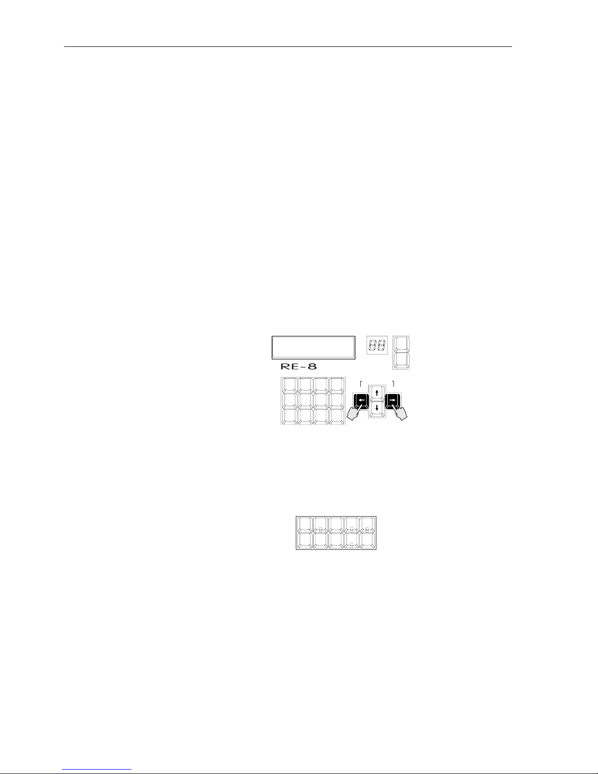
Determining Disk Space Remaining Using Cursor Keys. The left/right arrow
keys have another extremely useful function—that is to show, in track minutes,
the amount of disk space remaining.
1. Arm the tracks you wish to record upon. (You may bypass this part of the
procedure if you only need to know the total recording time remaining for
one track.)
2. Press and hold the left and right arrow keys simultaneously. The LCD
will show an A, B and C with a number. The A, B and C each represent a
block of eight tracks. The number next to the letters represents the time in
minutes that you can record given the number of tracks armed. If tracks are
armed for a particular disk, the time left number for that disk will flash on and
off.
The display is in actual recording minutes available—if you have 20 minutes of
track time available on Disk 1, and no tracks armed, it shows 20 minutes. If,
however, you have two tracks armed for recording, it will show 10 minutes (i.e.
10 minutes per track x 2 tracks = 20 minutes). If you change the number of
armed tracks, the remaining time number(s) will change accordingly.
Please Note: You may check available disk space at any time—even during
recording.
6.2.8 Utility Keys
This group of RE-8 keys contains functions that are broken out from within the
RADAR menu system. Most have been described elsewhere in this manual;
cross references to the appropriate manual sections are provided.
UNDO: See either §3.11 (Recording), or §7.2 (Editing).
DIGITAL I/O: See §3.17.
CANCEL: Cancels or exits from current operation.
SHIFT: Selects 2nd (blue) functions on RE-8 or front panel.
VARISPEED: See §3.8.
MARK LOC: See §3.13.
EDIT LOC: See §3.13.
CHASE: See §5.3.
SYNC/OFFSET: See §5.4.
UNDO
DIGITAL
I/O
BACKUP
PROJ
VARI-
SPEED
SHIFT
CANCEL
MARK
LOC
EDIT
LOC
CHASE
OFFSET
SYNC
HRS/BAR MIN/ BEAT SEC/STEP FRM SUB
REMOTE EDITING CONTROLLER
DISK SPACE REMAINING
123
456
789
UNDO
CANCEL
MENU
PREV
–
+
RECORD TIME LEFT
A012 B023 C004
Edition 2 (Printed in Japan)
6-6 SECTION 6
Page 99
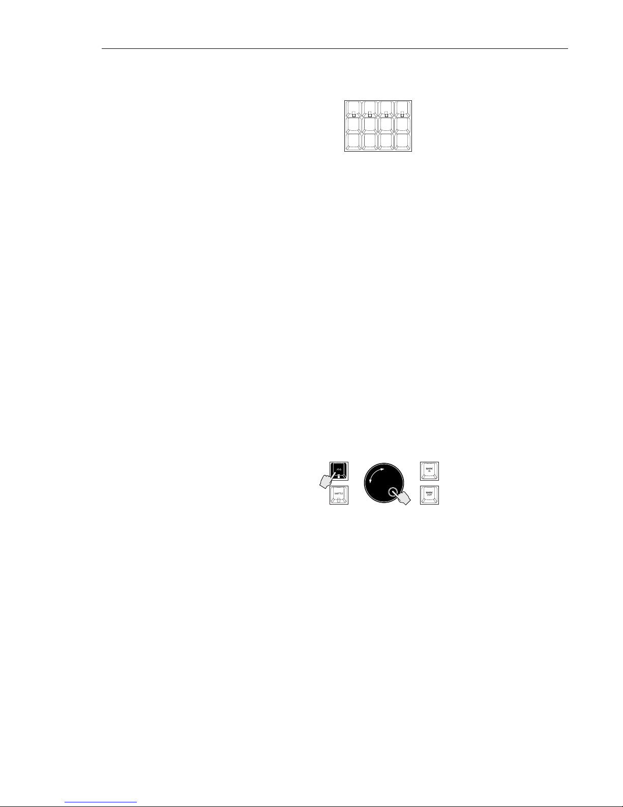
6.2.9 RE-8 Dedicated Editing Keys
This area represents many RADAR editing features with dedicated keys:
These features are described elsewhere in this manual; cross references appear
here:
AUTO PLAY:See §3.13.4.
AUTO PUNCH: See §3.10.
CYCLE: See §3.15.
PRE ROLL: See §3.16.
EDIT function keys: See Section 7.
6.2.10 Jog/Shuttle Wheel
RADAR’s Jog/Shuttle modes provide fast, precise location in recorded material.
Shuttle mode uses the jog wheel to vary the speed and direction of audio for
locating points; Jog mode allows you to “scrub” the audio to find exact
locations.
Please Note: The jog wheel may also be used as a convenient control device
when scrolling through RADAR’s menus. When used as an input device,
turning the wheel to the right increases the value on screen, and turning it to
the left decreases the value.
6.2.10.1 Entering Jog Mode
Press the JOG key to the left of the wheel to engage Jog mode:
Turning the wheel clockwise or counterclockwise produces variable speed
playback for as long as you continue turning it. When you stop turning the
wheel, playback will stop. The speed of playback varies from scrub where you
can accurately locate the first transient of an audio waveform by rocking the
wheel gently forward and backward to slightly above normal playback speed.
Jog “Bump”: You may “bump” the current location while in Jog by pressing the
cursor left or right keys. Each cursor press will nudge the jog location by the
smallest possible wheel increment.
To exit Jog mode, press any key (including the JOG key).
1
2
AUTO
PLAY
AUTO
PUNCH
ERASE
PRE
ROLL
MODIFY
EDIT
ERASE
SLIDE
LOOP
CUT COPY
LISTEN
PASTE
MOVE
RE-8 SESSION CONTROLLER FEATURES 6-7
Edition 2 (Printed in Japan)
Page 100

6.2.10.2 Entering Shuttle Mode
Press the SHUTTLE key (located below the JOG key) at any time to engage
Shuttle mode:
Shuttle produces playback at variable speeds like Jog with one difference; when
you stop turning the wheel, playback continues at the current speed until you
move the wheel again or press a transport key.
To exit Shuttle mode, press any key including the SHUTTLE key.
6.2.11 MARK IN & MARK OUT Keys
The MARK IN and MARK OUT keys set temporary location markers for audio
editing and transport locating. Mark In defines the beginning of a clip and
Mark Out defines the end point. Audio between these two points can then be
placed on the clipboard, deleted or erased. (You may use the cursor keys to
audition the audio between and around the Mark points! See §6.2.7 for details.)
The Mark In and Out points are not only used for editing, but are also useful as
Auto Location points that you do not want to store permanently. Mark In and
Out points can be recalled in the same way as location points.
6.2.11.1 Defining a Location using Mark In
1. Cue to a desired location using the transport, auto locate, wheel or
SMPTE time entry functions.
2. Press MARK IN. This can be pressed during playback, record or with the
transport stopped.
During playback or recording, repeated pressing of a MARK key will
continuously update that point to reflect the new location and delete the
previous one.
6.2.11.2 Defining a Location using Mark Out
1. Cue to a desired location using the transport, auto locate, wheel or
enter time functions.
2. Press MARK OUT during any transport mode. This can be pressed
during playback, record or with the transport stopped.
If you will be using Mark Out to define the end point of an audio clip, this
point must be after Mark In. This is not necessary if you are using Mark Out as a
temporary location point.
During playback or recording, repeated pressing of a MARK key will
continuously update that point to reflect the new location, and will delete the
previous Mark.
2
1
Edition 2 (Printed in Japan)
6-8 SECTION 6
 Loading...