

Page 1
2013- 08-20
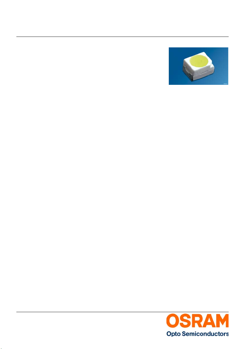
TOPLED
Datasheet
Version 3.0
LW T673
TOPLED, SM T LED with integrated reflecto r. With ou r
great experience in SMT LED we are able to offer a
high quality product for all kind of applications.
TOPLED, SMT-LED mit integriertem Reflektor. Mit
unserer großen Erfahrung in SMT LED sind wir in der
Lage, ein qualitativ hochwertiges Produkt für alle Arten
von Anwendungen anzubieten.
Features: Besondere Merkmale:
• Package: white PLCC-2 package, colored
diffused resin
• Technology: InGaN • Technologie: InGaN
• Viewing angle at 50 % I
Emitter)
• Color: Cx = 0.33, Cy = 0.33 acc. to CIE 1931
(white)
• Corrosion Robustness: Improved corrosion
robustness
: 120° (Lambertian
V
• Gehäusetyp: weisses PLCC-2 Gehäuse, farbiger
diffuser Verguss
• Abstrahlwinkel bei 50 % IV: 120° (Lambertscher
Strahler)
• Farbe: Cx = 0.33, Cy = 0.33 nach CIE 1931 (weiß)
• Korr osionsstabilität: Verbesserte
Korrosionsstabilität
Applications Anwendungen
• Automotive Interior Lighting • Automobilbeleuchtung innen
• Pushbuttons and Switches • Schalter und Taster
• Signal and Symbol Luminary • Signal- und Symbolleuchten
• White Goods Lighting • Weiße Ware
2013-08-20 1
Page 2

Version 3.0 LW T673
Ordering Information
Bestellinformation
Type: Luminous Intensity
Typ: Lichtstärke
1) pa ge 22
1) Seite 22
IF = 10 mA
IV [mcd]
LW T673-P1S1-FKPL 45 ... 224 Q65111A2043
Note: The above Type Numbers represent the order groups which include only a few brightness groups (see page 5). Only one group will be shipped on each
pack ing unit (t here will be no mixi ng of two groups on each pac king unit) . E. g. LW T673-P1S 1-FKPL me ans that only one group P1, P2, Q1, Q2, R1 ,
R2, S1 will be shippable for any packing unit. In order to ensure availability, single brightness groups will not be orderable.
In a simila r manner for colors wh ere wavelength gr oups are m easured and binne d, single ch romatic ity coord inate group s will be shipped on any one
reel. E. g. LW T673-P1S1-FKPL means that only one wavelength group FK, FL, GK, GL, HK, HL, IK, IL, JK, JL, KK, KL, LK, LL, MK, ML, NK, NL, OK,
OL, PK, PL will be shippable. LW T673-P1S1-FKPL means that the device will be shipped within the specified limits as stated on page 6. In order to
ensure ava ilability, single chrom aticity coordinate groups will not be orderable (see page 6for explanatio n).
Anm.: Die oben genannten Typbezeichnungen umfassen die bestellbaren Selektionen. Diese bestehen aus wenigen Helligkeitsgruppen (siehe Seite 5). Es
wird nur eine einzige Helligkeitsgruppe pro Verpackungseinheit geliefert. Z. B. LW T673-P1S1-FKPL bedeutet, dass in einer Verpackungs einheit nur
eine der Helligkeitsgruppen P1, P2, Q1, Q2, R1, R2, S1 enhalten ist. Um die Liefersicherheit zu gewährleisten, können einzelne Helligkeitsgruppen
nicht be stellt werden.
In a simila r manner for colors wh ere wavelength gr oups are m easured and binne d, single ch romatic ity coord inate group s will be shipped on any one
reel. E. g. LW T673-P1S1-FKPL means that only one wavelength group FK, FL, GK, GL, HK, HL, IK, IL, JK, JL, KK, KL, LK, LL, MK, ML, NK, NL, OK,
OL, PK, PL will be shippable. LW T673-P1S1-FKPL means that the device will be shipped within the specified limits as stated on page 6. In order to
ensure ava ilability, single chrom aticity coordinate groups will not be orderable (see page 6for explanatio n).
Ordering Code
Bestellnummer
2013-08-20 2
Page 3
Version 3.0 LW T673
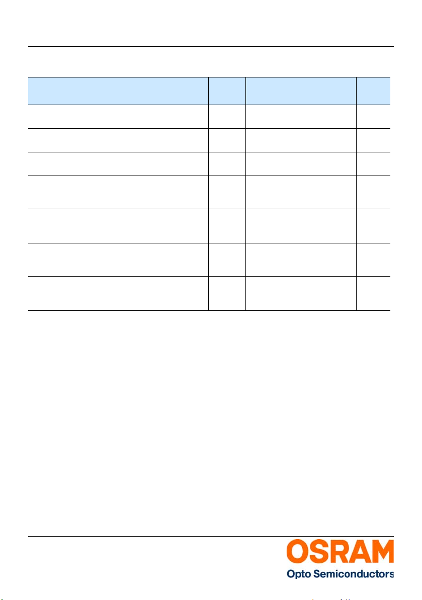
Maximum Ratings
Grenzwerte
Parameter Symbol Values Unit
Bezeichnung Symbol Werte Einheit
Operating temperature range
Betriebstemperatur
Storage temperature range
Lagertemperatur
Junction temperature
Sperrschichttemperatur
Forward current
Durchlassstrom
(T
= 25 °C)
S
Surge current
Stoßstrom
(t <= 10 μs; D = 0.005; T
Reverse voltage
Sperrspannung
2) Seite 22
2) page 22
= 25 °C)
S
(TS = 25 °C)
ESD withstand voltage
ESD Festigkeit
(acc. to ANSI/ESDA/JEDEC JS-001 - HBM)
T
op
T
stg
T
j
I
F
I
FM
V
R
V
ESD
-40 ... 100 °C
-40 ... 100 °C
110 °C
20 mA
200 mA
5V
up to 2 kV
2013-08-20 3
Page 4
Version 3.0 LW T673
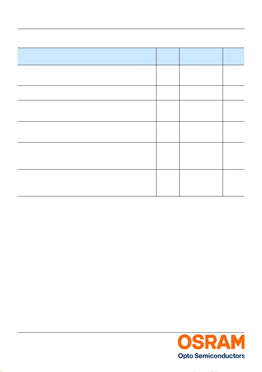
Characteristics (TS = 25 °C; IF = 10 mA) Kennwerte
Parameter Symbol Values Unit
Bezeichnung Symbol Werte Einheit
Chromaticity coordinates acc. to CIE 1931
3) pa ge 22
Farbkoordinaten nach CIE 1931
Viewing angle at 50 % I
Abstrahlwinkel bei 50 % I
Forward voltage
Durchlassspannung
Reverse current
Sperrstrom
V
4) pa ge 22
4) Seite 22
3) Seite 22
V
(VR = 5 V)
Real thermal resistance junction / ambient
5) pa ge 22 , 6) page 22
Realer Wärmewiderstand Sperrschicht /
Umgebung
Real thermal resistance junction / solder point
6) pa ge 22
Realer Wärmewiderstand Sperrschicht / Lötpad
6) Se ite 2 2
5) Seite 22 , 6) Seite 22
(typ.)
(typ.)
(typ.) 2ϕ 120 °
(min.)
(typ.)
(max.)
(typ.)
(max.)
(max.) R
(max.) R
Cx
Cy
V
F
V
F
V
F
I
R
I
R
th JA real
th JS real
0.33
0.33
2.70
3.10
3.40
0.01
10
-
-
V
V
V
μA
µA
400 K/W
180 K/W
2013-08-20 4
Page 5
Version 3.0 LW T673
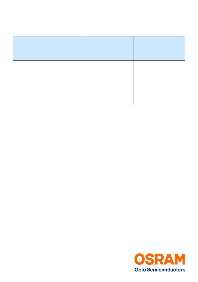
Brightness Groups
Helligkeitsgruppen
Group Luminous Intensity
Gruppe Lichtstärke
1) page 22
1) Seite 22
Luminous Intensity
1) page 22
Lichtstärke
1) Seite 22
Luminous Flux
Lichtstrom
(min.) Iv [mcd] (max.) Iv [mcd] (typ.) ΦV [mlm]
P1 45 56 150
P2 56 71 190
Q1 71 90 240
Q2 90 112 300
R1 112 140 380
R2 140 180 480
S1 180 224 610
No te: The st and ard shi ppi ng fo rm at fo r se ria l ty pes i ncl ude s ei the r a l owe r fam ily gro up, a n u ppe r fam ily gro up o r a g rou pin g of al l indivi dual b rightn ess g roups
of only a few brightness groups. Individual brightness groups cannot be ordered.
Anm.: Die St andardlief erform vo n Serienty pen beinhal tet entwed er eine unt ere Familie ngruppe, eine obere F amiliengr uppe oder eine Sam melgruppe , die aus
nur wenigen Helligkeitsgruppen besteht. Einzelne Helligkeitsgruppen sind nicht bestellbar.
7) page 22
7) Seite 22
2013-08-20 5
Page 6
Version 3.0 LW T673
FK
FL
GK
GL
HK
HL
IK
IL
JK
JL
KK
KL
LK
LL
MK
ML
NK
NL
OK
OL
PK
PL
0,20
0,22
0,24
0,26
0,28
0,30
0,32
0,34
0,36
0,38
0,40
0,23
0,25
0,27
0,29
0,31
0,33
0,35
0,37
0,39
0,41
0,43
Cx
Cy
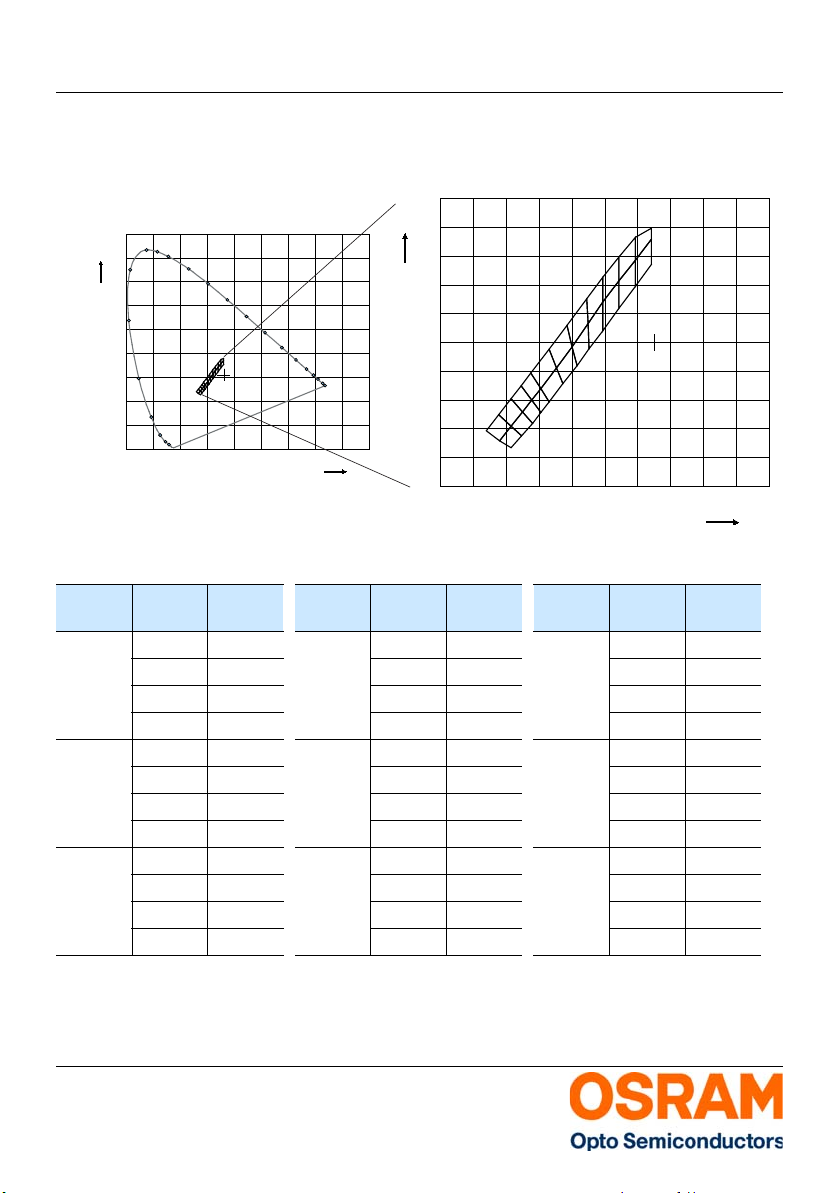
Chromaticity Coordinate Groups
Farbortgruppen
0,90
Cy
0,80
510
0,70
0,60
500
0,50
0,40
0,30
490
0,20
0,10
0,00
Color Chromaticity Groups
Farbortgruppen
Group
3) Seite 22
520
530
540
550
560
570
580
480
470
460
450
0,00
0,10
0,20
0,30
0,40
0,50
3) page 22
3) Seite 22
Cx Cy Group
590
0,60
Gruppe
FL 0.2580 0.2390
0.2655 0.2500
0.2660 0.2320
0.2730 0.2420
FK 0.2660 0.2320
0.2730 0.2270
0.2730 0.2420
0.2795 0.2355
GL 0.2655 0.2500
2013-08-20 6
0.2730 0.2420
0.2730 0.2610
0.2800 0.2520
3) page 22
600
610
620
630
650
0,70
0,80
0,90
Cx
Gruppe
Cx Cy Group
Gruppe
Cx Cy
JL 0.2850 0.2790 NL 0.3288 0.3282
0.2910 0.2680 0.3288 0.3453
0.2960 0.2955 0.3386 0.3426
0.3005 0.2825 0.3386 0.3591
JK 0.2910 0.2680 NK 0.3288 0.3081
0.2960 0.2590 0.3288 0.3282
0.3005 0.2825 0.3386 0.3235
0.3045 0.2715 0.3386 0.3426
KL 0.2960 0.2955 OL 0.3386 0.3426
0.3005 0.2825 0.3386 0.3591
0.3070 0.3120 0.3484 0.3571
0.3100 0.2970 0.3484 0.3730
Page 7
Version 3.0 LW T673
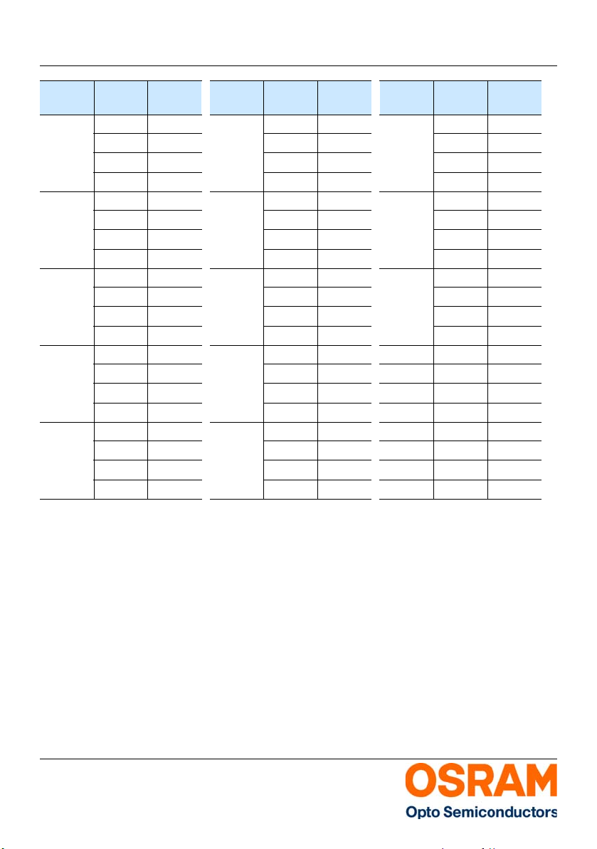
Group
Gruppe
GK 0.2730 0.2420 KK 0.3005 0.2825 OK 0.3386 0.3235
HL 0.2730 0.2610
HK 0.2800 0.2520
IL 0.2790 0.2700
IK 0.2855 0.2600 MK 0.3197 0.3131
Cx Cy Group
Gruppe
0.2795 0.2355
0.2800 0.2520
0.2860 0.2440
LL 0.3070 0.3120 PL 0.3484 0.3571
0.2790 0.2700
0.2800 0.2520
0.2855 0.2600
LK 0.3100 0.2970 PK 0.3484 0.3388
0.2855 0.2600
0.2860 0.2440
0.2910 0.2515
ML 0.3189 0.3302
0.2850 0.2790 0.3197 0.3131
0.2855 0.2600 0.3288 0.3282
0.2910 0.2680 0.3288 0.3452
0.2910 0.2515 0.3205 0.2956
0.2910 0.2680 0.3288 0.3081
0.2960 0.2590 0.3288 0.3282
Cx Cy Group
0.3045 0.2715 0.3386 0.3426
0.3100 0.2970 0.3484 0.3388
0.3130 0.2840 0.3484 0.3571
0.3100 0.2970 0.3484 0.3730
0.3189 0.3302 0.3582 0.3715
0.3197 0.3131 0.3582 0.3792
0.3130 0.2840 0.3484 0.3571
0.3197 0.3131 0.3582 0.3542
0.3205 0.2956 0.3582 0.3715
Cx Cy
Gruppe
2013-08-20 7
Page 8
Version 3.0 LW T673
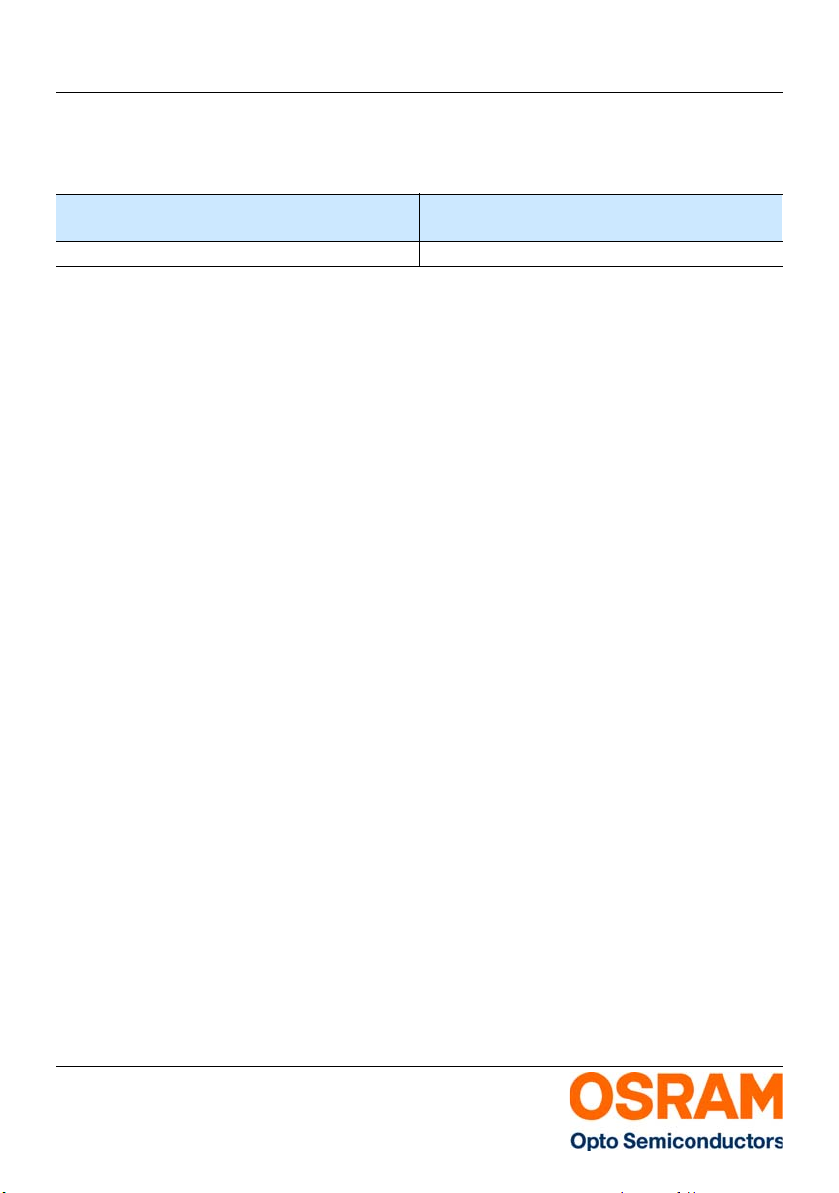
Group Name on Label
Gruppenbezeichnung auf Etikett
Example: P1-FK
Beispiel: P1-FK
Brightness
Helligkeit
P1 FK
Note: No packing unit / tape ever contains more than one group for each selection.
Anm.: In einer Verpackungseinheit / Gurt ist immer nur eine Gruppe für jede Selektion enthalten.
Chromaticity Coordinate
Farbort
2013-08-20 8
Page 9
Version 3.0 LW T673
0
400
λ
OHL01461
I
20
40
60
80
%
100
rel
nm
V
λ
450 500 550 600 650 700 750
0
0.2
0.4
1.0
0.8
0.6
ϕ
1.0 0.8 0.6 0.4
0˚10˚20˚40˚ 30˚
OHL01660
50˚
60˚
70˚
80˚
90˚
100˚
0˚ 20˚ 40˚ 60˚ 80˚ 100˚ 120˚
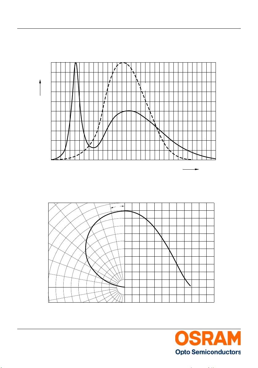
Relative Spectral Emission - V(λ) = Standard eye response curve
7) page 22
Relative spektrale Emission - V(λ) = spektrale Augenempfindlichkeit
I
= f (λ); TS = 25 °C; IF = 10 mA
rel
Radiation Characteristics
Abstrahlcharakteristik
I
= f (ϕ); TS = 25 °C
rel
7) page 22
7) Seite 22
7) Seite 22
2013-08-20 9
Page 10
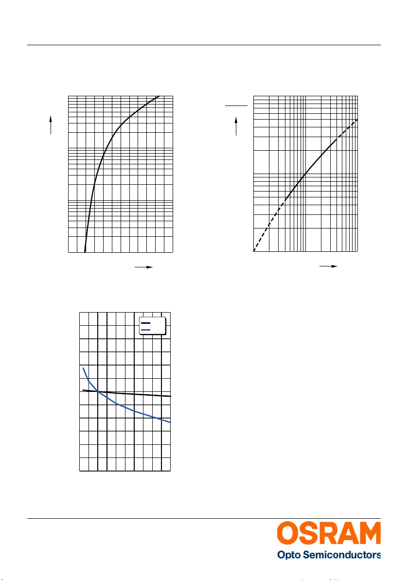
Version 3.0 LW T673
OHL11494
10
-1
2.5 3.0 3.5 4.0 4.5 V 5.0
0
10
1
10
10
2
5
5
mA
5
2.0
I
F
V
F
OHL10494
I
F
1
10
0
10
10
-1
10
10
10
2
mA 10
5
5
5
(10 mA)
V
V
I
I
Forward Current
Durchlassstrom
7) page 22
7) Seite 22
IF = f (VF); TS = 25 °C
Chromaticity Coordinate Shift
Farbortverschiebung
7) Seite 22
Cx, Cy = f(IF); TS = 25 °C
0.03
Cx
Δ
Δ
Cy
0.02
59IDC0502
7) page 22
: ΔCx
: ΔCy
Relative Luminous Intensity
Relative Lichtstärke
7) Seite 22 , 8) Seite 22
IV/IV(10 mA) = f(IF); TS = 25 °C
7) page 22 , 8) page 22
0.01
0.00
-0.01
2013-08-20 10
-0.02
-0.03
0 1020304050
IF [mA]
Page 11
Version 3.0 LW T673
-0.3
-60
T
OHL02352
-40 -20 0 20 40 60 ˚C 100
V
-0.2
-0.1
0.0
0.1
0.2
0.4
j
F
Δ
V
0.3
OHL01870
-60
0
T
˚C
V (25 ˚C)
I
I
V
-40 -20 0 20 40 60 100
0.2
0.4
0.6
0.8
1.0
1.2
1.4
j
-40 -20 0 20 40 60 80
Tj [°C]
-0,03
-0,02
-0,01
0,00
0,01
0,02
0,03
ΔCx; ΔCy
: Cx
: Cy
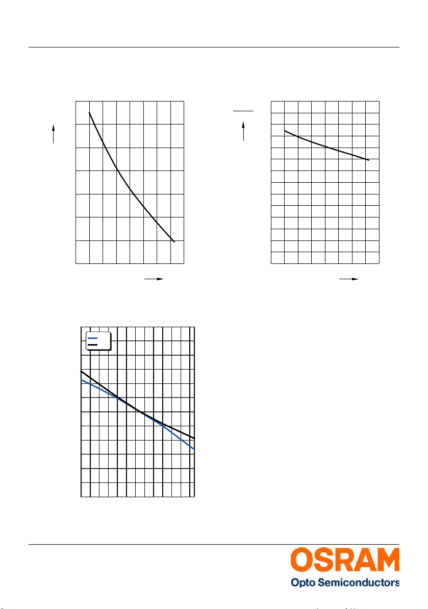
Relative Forward Voltage
Relative Vorwärtsspannung
7) page 22
7) Seite 22
ΔVF = VF - VF(25°C) = f(Tj); IF = 10 mA
Chromaticity Coordinate Shift
Farbortverschiebung
7) Seite 22
Cx, Cy = f(Tj); IF = 10 mA
7) page 22
Relative Luminous Intensity
Relative Lichtstärke
7) Seite 22
IV/IV(25)°C = f(Tj); IF = 10 mA
7) page 22
2013-08-20 11
Page 12
Version 3.0 LW T673
temp. solder point
40
200
T
0
S
1008060
˚C
T
I
F
mA
OHL20867
5
10
15
20
25
temp. ambient
T
A
TAT
S
OHL01965
10
-5
p
t
F
I
10-410-310-210-110010
1
0
A
2
10s
D
t
P
T
=
T
P
t
I
F
0.01
0.05
0.2
0.1
0.005
0.02
0.5
D
=
1
0.05
0.10
0.15
0.25
OHL01966
10
-5
p
t
F
I
10-410-310-210-110010
1
0
A
2
10s
D
t
P
T
=
T
P
t
I
F
0.01
0.05
0.2
0.1
0.005
0.02
0.5
D
=
1
0.05
0.10
0.15
0.25
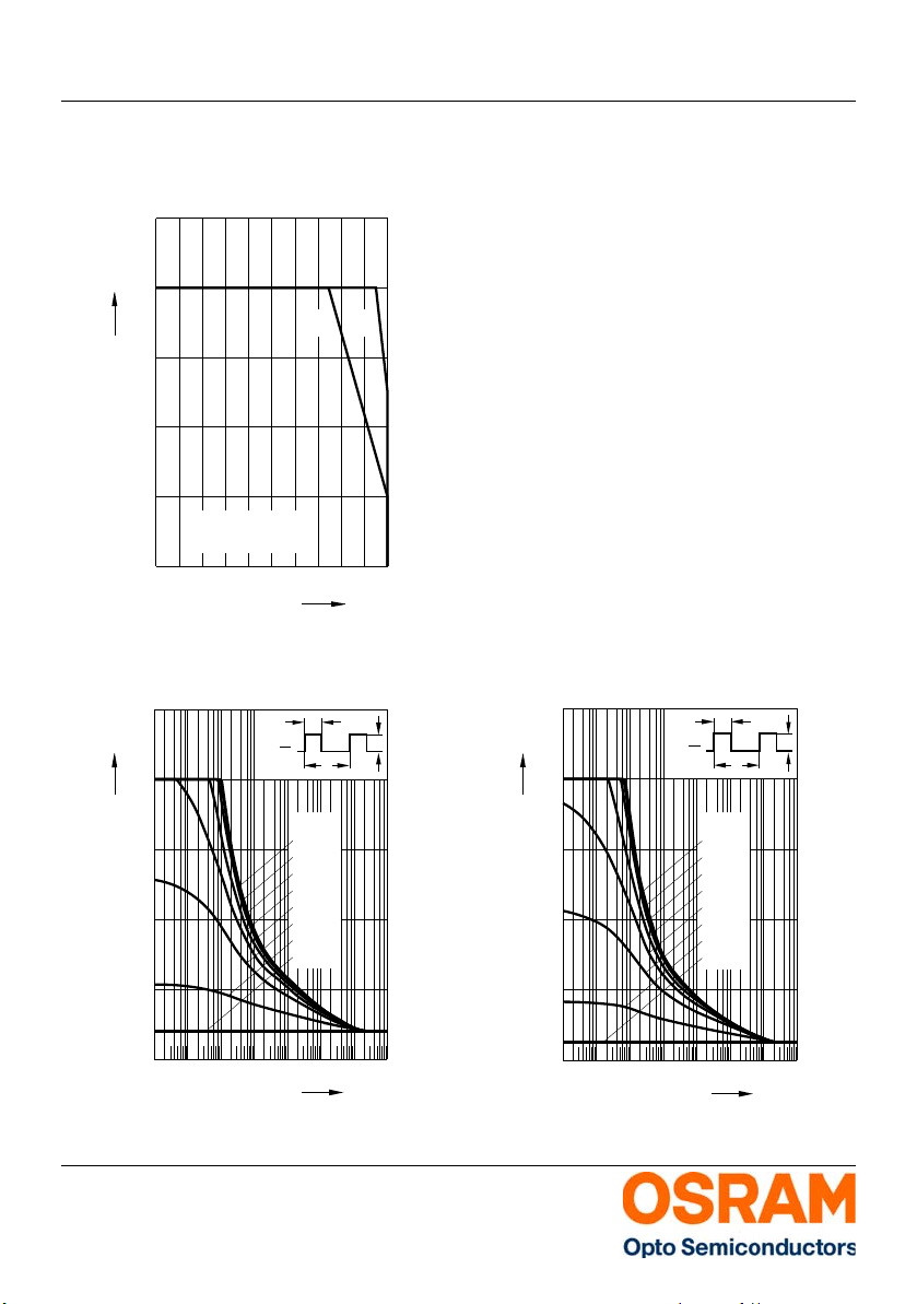
Max. Permissible Forward Current
Max. zulässiger Durchlassstrom
IF = f (T)
Permissible Pulse Handling Capability
Zulässige Impulsbelastbarkeit I
D: Duty cycle, TA = 25 °C
2013-08-20 12
= f(tp)
F
Permissible Pulse Handling Capability
Zulässige Impulsbelastbarkeit I
D: Duty cycle, TA = 85 °C
= f(tp)
F
Page 13
Version 3.0 LW T673
GPLY6724
0.7 (0.028)
0.9 (0.035)
1.7 (0.067)
2.1 (0.083)
0.12 (0.005)
0.18 (0.007)
0.5 (0.020)
1.1 (0.043)
3.3 (0.130)
3.7 (0.146)
0.4 (0.016)
0.6 (0.024)
2.6 (0.102)
3.0 (0.118)
2.1 (0.083)
2.3 (0.091)
Cathode marking
3.0 (0.118)
3.4 (0.134)
(2.4) (0.095)
0.1 (0.004) (typ.)
4˚±1
A
C
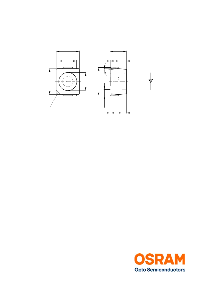
Package Outline
Maßzeichnung
9) page 22
9) Seite 22
Approximate Weight: 34 mg
Gewicht: 34 mg
Mark: bevelled edge (Cathode)
Markierung: abgeschrägte Ecke (Kathode)
Corrosion robustness: Test conditions: 40 °C / 90 % rh / 15 ppm H
= Stricter than IEC 60068-2-43 (H
/ 10 ppm H
= Regarding relevant gas (H
S / 21 days]
2
60068-2-60 (method 4) [25 °C / 75 % rh / 200 ppb
SO
, 200 ppb NO2,10 ppb Cl2 / 21 days]
2
S) [25°C / 75 % rh
2
S) stricter than EN
2
Korrosionsfestigkeit: Test Kondition: 40°C / 90 % rh / 15 ppm H
= Besser als IEC 60068-2-43 (H
10 ppm H
= Bezogen auf das Gas (H
S / 21 Tage]
2
60068-2-60 (method 4) [25°C / 75 % rh / 200ppb
, 200ppb NO2,10ppb Cl2 / 21 Tage]
SO
2
S) [25°C / 75 % rh /
2
S) besser als EN
2
S / 336 h
2
S / 336 h
2
2013-08-20 13
Page 14
Version 3.0 LW T673
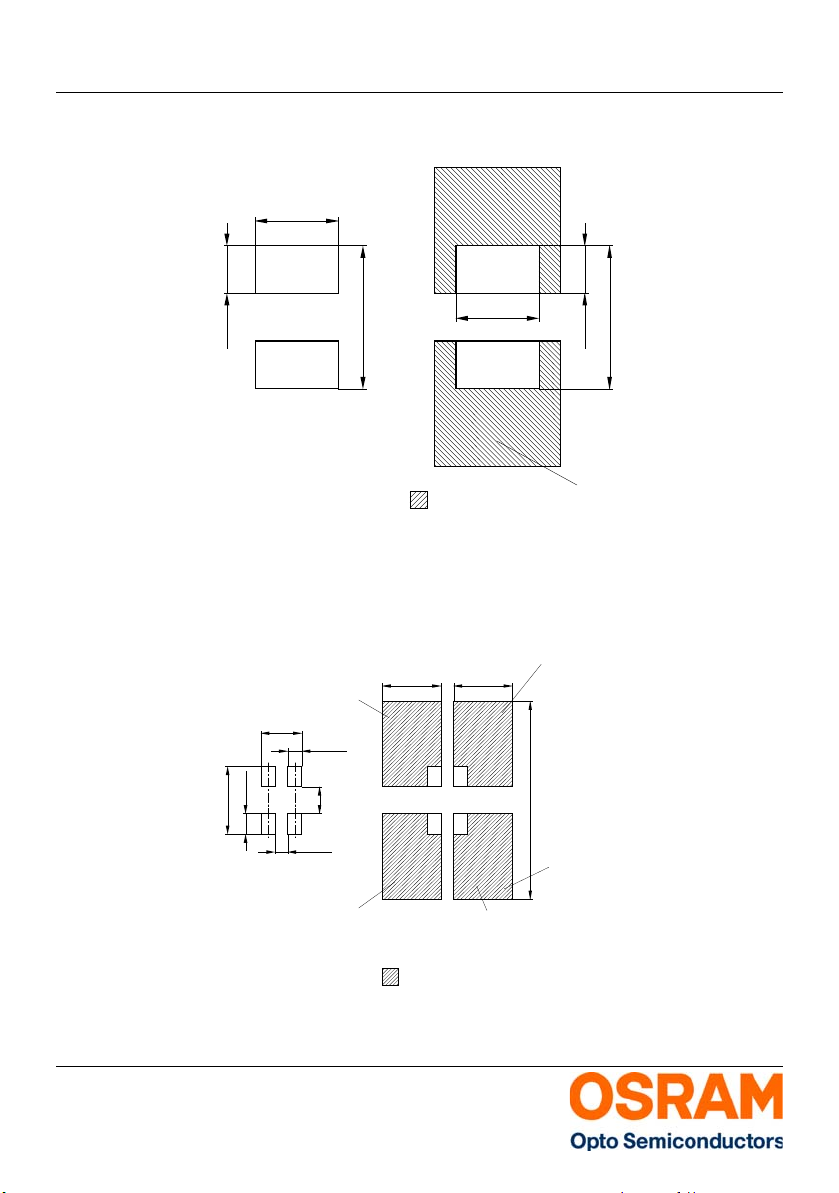
OHLPY970
4.5 (0.177)
2.6 (0.102)
1.5 (0.059)
Cu-area > 16 mm
Cu-Fläche > 16 mm
2
2
Solder resist
Lötstopplack
4.5 (0.177)
1.5 (0.059)
2.6 (0.102)
Padgeometrie für
improved heat dissipation
verbesserte Wärmeableitung
Paddesign for
OHLPY440
Padgeometrie für
verbesserte Wärmeableitung
improved heat dissipation
Paddesign for
Lötstoplack
Solder resist
0.8 (0.031)
3.7 (0.146)
1.1 (0.043)
2.3 (0.091)
3.3 (0.130)
1.5 (0.059)
11.1 (0.437)
Cu Fläche / 16 mm per pad
2
Cu-area
_
<
3.3 (0.130)
Kathode/
Cathode
Anode
0.7 (0.028)
Fläche darf bei Verwendung von TOPLED
®
For TOPLED® assembly do not use
elektrisch nicht beschaltet werden.
this area for electrical contact
Fläche darf bei Verwendung von TOPLED
®
For TOPLED® assembly do not use
elektrisch nicht beschaltet werden.
this area for electrical contact
Recommended Solder Pad
Empfohlenes Lötpaddesign
Recommended Solder Pad
Empfohlenes Lötpaddesign
Reflow Soldering / Reflow Löten
9) page 22
9) Seite 22
9) page 22
9) Seite 22
Reflow soldering
Reflow-Löten
Reflow soldering
Reflow-Löten
2013-08-20 14
Page 15
Version 3.0 LW T673
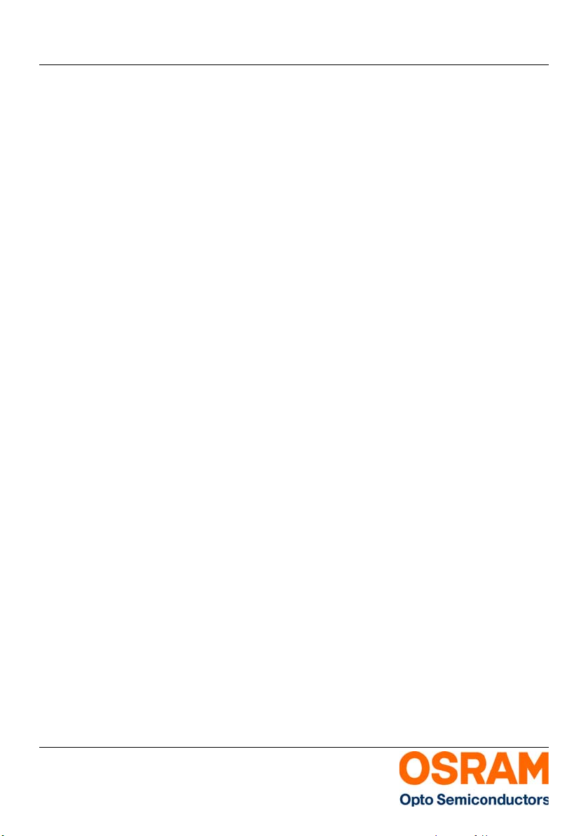
Note: The lower solder pad layout represents the
Anm.: Das untere Lötpaddesign zeigt das empfohlene
recommended solder pad useable for TOPLED and
Power TOPLED (combi solder pad).
Lötpaddesign, welches sowohl für TOPLED als
auch Power TOPLED verwendbar ist
(Kombi-Lötpaddesign).
2013-08-20 15
Page 16
Version 3.0 LW T673
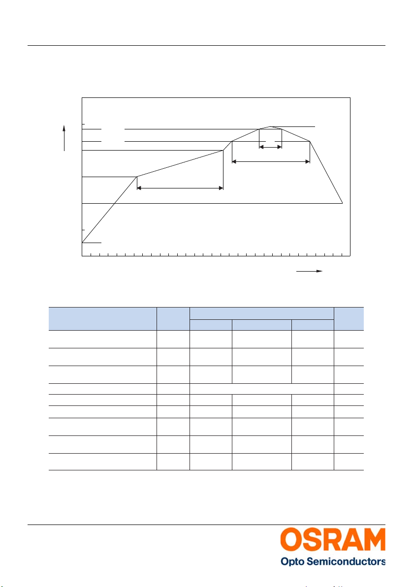
OHA04612
Profile Feature
Profil-Charakteristik
Ramp-up rate to preheat*
)
25 °C to 150 °C
2 3 K/s
Time t
S
T
Smin
to T
Smax
t
S
t
L
t
P
T
L
T
P
100 12060
10 20 30
80 100
217
2 3
245 260
3 6
Time
25 °C to T
P
Time within 5 °C of the specified peak
temperature T
P
- 5 K
Ramp-down rate*
T
P
to 100 °C
All temperatures refer to the center of the package, measured on the top of the component
* slope calculation DT/Dt: Dt max. 5 s; fulfillment for the whole T-range
Ramp-up rate to peak*
)
T
Smax
to T
P
Liquidus temperature
Peak temperature
Time above liquidus temperature
Symbol
Symbol
Unit
Einheit
Pb-Free (SnAgCu) Assembly
Minimum MaximumRecommendation
K/s
K/s
s
s
s
s
°C
°C
480
Reflow Soldering Profile
Reflow-Lötprofil
Preconditioning: JEDEC Level 2 acc. to JEDEC J-STD-020D.01
T
p
OHA04525
245 ˚C
300
˚C
T
250
200
240 ˚C
217 ˚C
t
P
t
L
150
t
S
100
50
25 ˚C
0
0
2013-08-20 16
50 100 150 200 250 300
s
t
Page 17
Version 3.0 LW T673
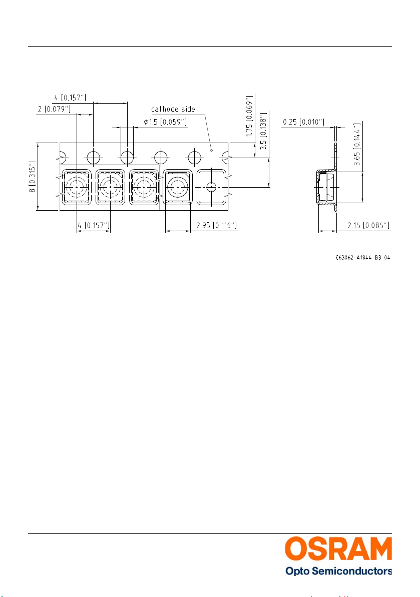
Method of Taping
Gurtung
9) Seite 22
9) page 22
2013-08-20 17
Page 18
Version 3.0 LW T673
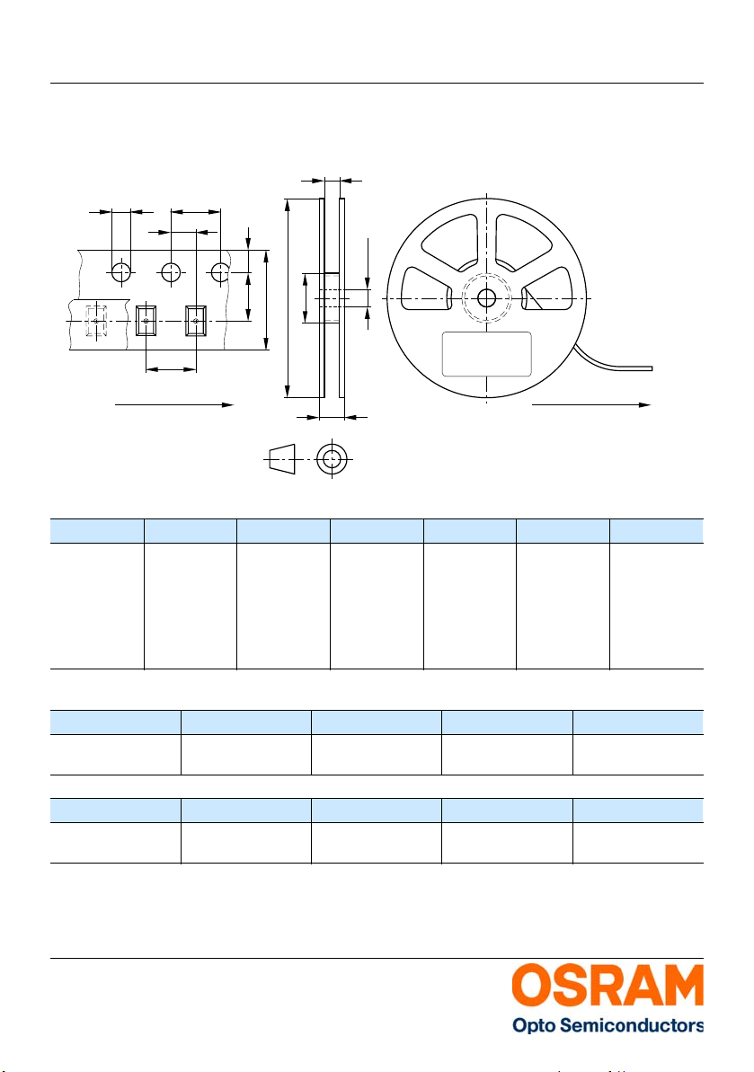
Tape and Reel
Gurtverpackung
8 mm tape with 2000 pcs. on ∅ 180 mm reel, 8000 pcs. on ∅ 330 mm reel
W
1
D
0
P
0
P
2
±0.25
13.0
FE
A
N
W
P
1
Direction of unreeling
W
2
Leader:
Trailer:
Label
min. 400 mm *
min. 160 mm *
*) Dimensions acc. to IEC 60286-3; EIA 481-D
Tape dimensions in mm (inch)
Tape dimensions in mm (inc h)
W P
0
8 +0.3/-0.1 4 ± 0.1
(0.157 ±
0.004)
P
1
2 ± 0.05
(0.079 ±
0.002)
P
2
2 ± 0.05
(0.079 ±
0.002)
D
0
1.5 ± 0.1
(0.059 +
0.004)
or
4 ± 0.1
(0.157 ±
0.004)
Reel dimensions in mm (inch)
Reel dimensions in mm (inch)
A W N
min
W
1
180 (7) 8 (0.315) 60 (2.362) 8.4 + 2 (0.331 +
0.079)
Direction of unreeling
E F
1.75 ± 0.1
(0.069 ±
0.004)
W
2max
14.4 (0.567)
OHAY0324
3.5 ± 0.05
(0.217 ±
0.002)
Reel dimensions in mm (inch)
A W N
min
W
1
330 (13) 8 (0.315) 60 (2.362) 8.4 + 2 (0.331 +
0.079)
2013-08-20 18
W
2max
14.4 (0.567)
Page 19
Version 3.0 LW T673
OHA04563
(G) GROUP:
1234567890
(1T) LOT NO: (9D) D/C:
1234
(X) PROD NO:
123456789
(6P) BATCH NO:
1234567890
LX XXXX
RoHS Compliant
BIN1: XX-XX-X-XXX-X
ML2Temp ST
260 °C R
Pack: R18
DEMY 022
B_R999_1880.1642 R
9999
(Q)QTY:
Semiconductors
OSRAM Opto
XX-XX-X-X
OHA00539
O
S
R
A
M
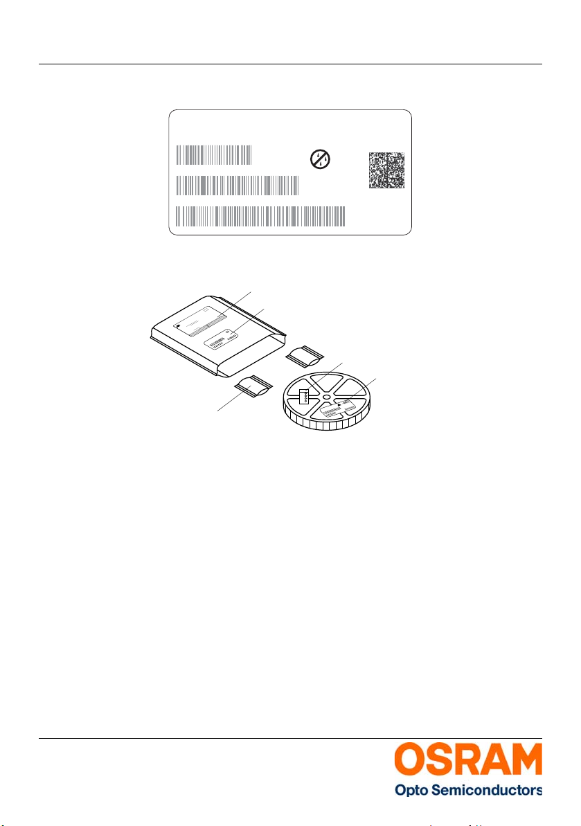
Moisture-sensitive label or print
Barcode label
Desiccant
Humidity indicator
Barcode label
O
S
R
A
M
Please check the HIC immidiately after
bag opening.
Discard if circles overrun.
Avoid metal contact.
WET
Do not eat.
Comparator
check dot
parts still adequately dry.
examine units, if necessary
examine units, if necessary
5%
15%
10%
bake units
bake units
If wet,
change desiccant
If wet,
Humidity Indicator
MIL-I-8835
If wet,
M
o
i
s
t
u
r
e
L
e
v
e
l
3
F
l
o
o
r
t
i
m
e
1
6
8
H
o
u
r
s
M
o
i
s
t
u
r
e
L
e
v
e
l
6
F
l
o
o
r
t
i
m
e
6
H
o
u
r
s
a
)
H
u
m
i
d
i
t
y
I
n
d
i
c
a
t
o
r
C
a
r
d
i
s
>
1
0
%
w
h
e
n
r
e
a
d
a
t
2
3
˚
C
±
5
˚
C
,
o
r
r
e
f
l
o
w
,
v
a
p
o
r
-
p
h
a
s
e
r
e
f
l
o
w
,
o
r
e
q
u
i
v
a
l
e
n
t
p
r
o
c
e
s
s
i
n
g
(
p
e
a
k
p
a
c
k
a
g
e
2
.
A
f
t
e
r
t
h
i
s
b
a
g
i
s
o
p
e
n
e
d
,
d
e
v
i
c
e
s
t
h
a
t
w
i
l
l
b
e
s
u
b
j
e
c
t
e
d
t
o
i
n
f
r
a
r
e
d
1
.
S
h
e
l
f
l
i
f
e
i
n
s
e
a
l
e
d
b
a
g
:
2
4
m
o
n
t
h
s
a
t
<
4
0
˚
C
a
n
d
<
9
0
%
r
e
l
a
t
i
v
e
h
u
m
i
d
i
t
y
(
R
H
)
.
M
o
i
s
t
u
r
e
L
e
v
e
l
5
a
a
t
f
a
c
t
o
r
y
c
o
n
d
i
t
i
o
n
s
o
f
(
i
f
b
l
a
n
k
,
s
e
a
l
d
a
t
e
i
s
i
d
e
n
t
i
c
a
l
w
i
t
h
d
a
t
e
c
o
d
e
)
.
a
)
M
o
u
n
t
e
d
w
i
t
h
i
n
b
)
S
t
o
r
e
d
a
t
b
o
d
y
t
e
m
p
.
3
.
D
e
v
i
c
e
s
r
e
q
u
i
r
e
b
a
k
i
n
g
,
b
e
f
o
r
e
m
o
u
n
t
i
n
g
,
i
f
:
B
a
g
s
e
a
l
d
a
t
e
M
o
i
s
t
u
r
e
L
e
v
e
l
1
M
o
i
s
t
u
r
e
L
e
v
e
l
2
M
o
i
s
t
u
r
e
L
e
v
e
l
2
a
4
.
I
f
b
a
k
i
n
g
i
s
r
e
q
u
i
r
e
d
,
b
)
2
a
o
r
2
b
i
s
n
o
t
m
e
t
.
D
a
t
e
a
n
d
t
i
m
e
o
p
e
n
e
d
:
r
e
f
e
r
e
n
c
e
I
P
C
/
J
E
D
E
C
J
-
S
T
D
-
0
3
3
f
o
r
b
a
k
e
p
r
o
c
e
d
u
r
e
.
F
l
o
o
r
t
i
m
e
s
e
e
b
e
l
o
w
I
f
b
l
a
n
k
,
s
e
e
b
a
r
c
o
d
e
l
a
b
e
l
F
l
o
o
r
t
i
m
e
>
1
Y
e
a
r
F
l
o
o
r
t
i
m
e
1
Y
e
a
r
F
l
o
o
r
t
i
m
e
4
W
e
e
k
s
1
0
%
R
H
.
_
<
M
o
i
s
t
u
r
e
L
e
v
e
l
4
M
o
i
s
t
u
r
e
L
e
v
e
l
5
˚
C
)
.
O
P
T
O
S
E
M
I
C
O
N
D
U
C
T
O
R
S
M
O
I
S
T
U
R
E
S
E
N
S
I
T
I
V
E
T
h
i
s
b
a
g
c
o
n
t
a
i
n
s
C
A
U
T
I
O
N
F
l
o
o
r
t
i
m
e
7
2
H
o
u
r
s
F
l
o
o
r
t
i
m
e
4
8
H
o
u
r
s
F
l
o
o
r
t
i
m
e
2
4
H
o
u
r
s
3
0
˚
C
/
6
0
%
R
H
.
_
<
L
E
V
E
L
I
f
b
l
a
n
k
,
s
e
e
b
a
r
c
o
d
e
l
a
b
e
l
Barcode-P roduct-Label (BPL)
Barcode-Produkt-Etikett (BPL)
Dry Packing Process and Materials
Trockenverpackung und Materialien
Note: Moisture-sensitive product is packed in a dry bag containing desiccant and a humidity card.
Regarding dry pack you will find further information in the internet and in the Short Form Catalog in
chapter “Tape an d Reel” under the topic “ Dry Pack”. Here you will also find the nor mative references
like JEDEC.
Anm.: Feuchteempfindliche Produkte sind verpackt in einem Trockenbeutel zusammen mit einem
Trockenmittel und einer Feuchteindikatorkarte.
Bezüglich Trockenverpackung finden Sie weitere Hinweise im Internet und in unserem Short Form
Catalog im Kapitel “Gurtung und Verpackung” unter dem Punkt “Trockenverpackung”. Hier sind
Normenbezüge, unter anderem ein Auszug der JEDEC-Norm, enthalten.
2013-08-20 19
Page 20
Version 3.0 LW T673
OHA02044
P
ACKVAR:
R077
Additional TEXT
P
-
1
+
Q
-
1
M
u
l
t
i
T
O
P
L
E
D
Muster
O
S
R
A
M
O
p
t
o
S
e
m
i
c
o
n
d
u
c
t
o
r
s
(
6P) BAT
CH
N
O
:
(X) PROD NO:
1
0
(9D) D/C:
11
(
1T) LOT NO:
210021998
1
2
3
G
H
1
2
3
4
0
245
(Q)QTY:
2
0
0
0
0
1
4
4
(G
) GROUP:
2
60 C RT
240
C R
3
220 C R
ML
Bin3:
Bin2: Q-1-20
Bin1: P-1-20
L
S
Y
T
6
7
6
2
2a
Temp ST
R
1
8
DEMY
P
A
C
K
V
A
R
:
R
0
7
7
A
d
d
i
t
i
o
n
a
l
T
E
X
T
P-1+Q
-1
M
u
lti T
O
PL
E
D
Muster
O
S
R
A
M
O
p
t
o
S
e
m
i
c
o
n
d
u
c
t
o
r
s
(
6
P
)
B
A
T
C
H
N
O
:
(
X
)
P
R
O
D
N
O
:
1
0
(
9
D
)
D
/
C
:
11
(
1
T
)
L
O
T
N
O
:
2
1
0
0
2
1
9
9
8
1
23G
H1
23
4
0
245
(
Q
)
Q
T
Y
:
20
00
01
44
(
G
)
G
R
O
U
P
:
2
6
0
C
R
T
2
4
0
C
R
3
2
2
0
C
R
M
L
B
i
n
3
:
B
i
n
2
:
Q
-
1
-
2
0
B
i
n
1
:
P
-
1
-
2
0
L
S
Y
T
6
7
6
2
2
a
T
e
m
p
S
T
R
18
D
E
M
Y
O
SR
AM
Packing
Sealing label
Barcode label
M
o
i
s
t
u
r
e
L
e
v
e
l
3
F
l
o
o
r
t
i
m
e
1
6
8
H
o
u
r
s
M
o
i
s
t
u
r
e
L
e
v
e
l
6
F
l
o
o
r
t
i
m
e
6
H
o
u
r
s
a
)
H
u
m
i
d
i
t
y
I
n
d
i
c
a
t
o
r
C
a
r
d
i
s
>
1
0
%
w
h
e
n
r
e
a
d
a
t
2
3
˚
C
±
5
˚
C
,
o
r
r
e
f
l
o
w
,
v
a
p
o
r
-
p
h
a
s
e
r
e
f
l
o
w
,
o
r
e
q
u
i
v
a
l
e
n
t
p
r
o
c
e
s
s
i
n
g
(
p
e
a
k
p
a
c
k
a
g
e
2
.
A
f
t
e
r
t
h
i
s
b
a
g
i
s
o
p
e
n
e
d
,
d
e
v
i
c
e
s
t
h
a
t
w
i
l
l
b
e
s
u
b
j
e
c
t
e
d
t
o
i
n
f
r
a
r
e
d
1
.
S
h
e
l
f
l
i
f
e
i
n
s
e
a
l
e
d
b
a
g
:
2
4
m
o
n
t
h
s
a
t
<
4
0
˚
C
a
n
d
<
9
0
%
r
e
l
a
t
i
v
e
h
u
m
i
d
i
t
y
(
R
H
)
.
M
o
i
s
t
u
r
e
L
e
v
e
l
5
a
a
t
f
a
c
t
o
r
y
c
o
n
d
i
t
i
o
n
s
o
f
(
i
f
b
l
a
n
k
,
s
e
a
l
d
a
t
e
i
s
i
d
e
n
t
i
c
a
l
w
i
t
h
d
a
t
e
c
o
d
e
)
.
a
)
M
o
u
n
t
e
d
w
i
t
h
i
n
b
)
S
t
o
r
e
d
a
t
b
o
d
y
t
e
m
p
.
3
.
D
e
v
i
c
e
s
r
e
q
u
i
r
e
b
a
k
i
n
g
,
b
e
f
o
r
e
m
o
u
n
t
i
n
g
,
i
f
:
B
a
g
s
e
a
l
d
a
t
e
M
o
i
s
t
u
r
e
L
e
v
e
l
1
M
o
i
s
t
u
r
e
L
e
v
e
l
2
M
o
i
s
t
u
r
e
L
e
v
e
l
2
a
4
.
I
f
b
a
k
i
n
g
i
s
r
e
q
u
i
r
e
d
,
b
)
2
a
o
r
2
b
i
s
n
o
t
m
e
t
.
D
a
t
e
a
n
d
t
i
m
e
o
p
e
n
e
d
:
r
e
f
e
r
e
n
c
e
I
P
C
/
J
E
D
E
C
J
-
S
T
D
-
0
3
3
f
o
r
b
a
k
e
p
r
o
c
e
d
u
r
e
.
F
l
o
o
r
t
i
m
e
s
e
e
b
e
l
o
w
I
f
b
l
a
n
k
,
s
e
e
b
a
r
c
o
d
e
l
a
b
e
l
F
l
o
o
r
t
i
m
e
>
1
Y
e
a
r
F
l
o
o
r
t
i
m
e
1
Y
e
a
r
F
l
o
o
r
t
i
m
e
4
W
e
e
k
s
1
0
%
R
H
.
_
<
M
o
i
s
t
u
r
e
L
e
v
e
l
4
M
o
i
s
t
u
r
e
L
e
v
e
l
5
˚
C
)
.
O
P
T
O
S
E
M
I
C
O
N
D
U
C
T
O
R
S
M
O
I
S
T
U
R
E
S
E
N
S
I
T
I
V
E
T
h
i
s
b
a
g
c
o
n
t
a
i
n
s
C
A
U
T
I
O
N
F
l
o
o
r
t
i
m
e
7
2
H
o
u
r
s
F
l
o
o
r
t
i
m
e
4
8
H
o
u
r
s
F
l
o
o
r
t
i
m
e
2
4
H
o
u
r
s
3
0
˚
C
/
6
0
%
R
H
.
_
<
L
E
V
E
L
I
f
b
l
a
n
k
,
s
e
e
b
a
r
c
o
d
e
l
a
b
e
l
Barcode label
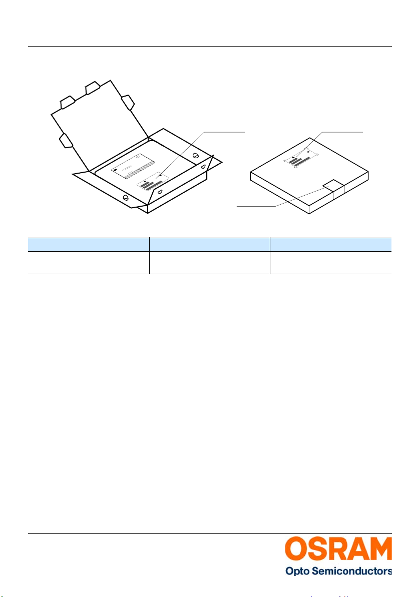
Transportation Packing and Materials
Kartonverpackung und Materialien
Dimensions of transportation box in mm (inch):
Width / Breite Length / Länge Height / Höhe
200 ± 5 (7.874 ± 0.196)
352 ± 5 (13.858 ± 0.196)
Notes Hinweise
The evaluat ion of eye safety occurs according to the
standard IEC 62471:200 8 ("photobiolog ical safety of
lamps and lamp systems"). Within the risk grouping
system of this CIE standard, the LED specified in this
data sheet fall into the class Exempt group
(exposure time 10000 s). Under real circumstances
(for exposure time, eye pupils, observation
distance), it is assumed that no endangerment to the
eye exists from these devices. As a matter of
principle, however, it should be mentioned that
intense light sources have a high secondary
exposure potential due to their blinding effect. As is
also true when viewing other bright light sources
(e.g. headlights), temporary reduction in visual
acuity and afterimages can occur, leading to
irritation, annoyance, visual impairment, and even
accidents, depending on the situation.
195 ± 5 (7.677 ± 0.1968)
352 ± 5 (13.858 ± 0.196)
Die Bewertung der Augensicherheit erfolgt nach
dem Standard IEC 62471:2008 ("photobiological
safety of lamps and lamp systems"). Im
Risikogruppensystem dieser CIE- Norm erfüllen die
in diesem Datenblatt angegebenen LEDs folgende
Gruppenanforderung - Exempt group
(Expositionsdauer 10000 s). Unter realen
Umständen (für Expositionsdauer, Augenpupille,
Betrachtungsabstand) geht damit von diesen
Bauelementen keinerlei Augengefährdung aus.
Grundsätzlich sollte jedoch erwähnt werden, dass
intensive Lichtquellen durch ihre Blendwirkung ein
hohes sekundäres Gefahrenpotenzial besitzen.
Nach einem Blick in eine helle Lichtquelle (z.B.
Autoscheinwerfer), kann ein temporär
eingeschränktes Sehvermögen oder auch
Nachbilder zu Irritationen, Belästigungen,
Beeinträchtigungen oder sogar Unfällen führen.
30 ± 5 (1.181 ± 0.196)
33 ± 5 (1.299 ± 0.196)
2013-08-20 20
Page 21
Version 3.0 LW T673
Date of Change: 2013-08-15
Revision Date: 2013-08-20
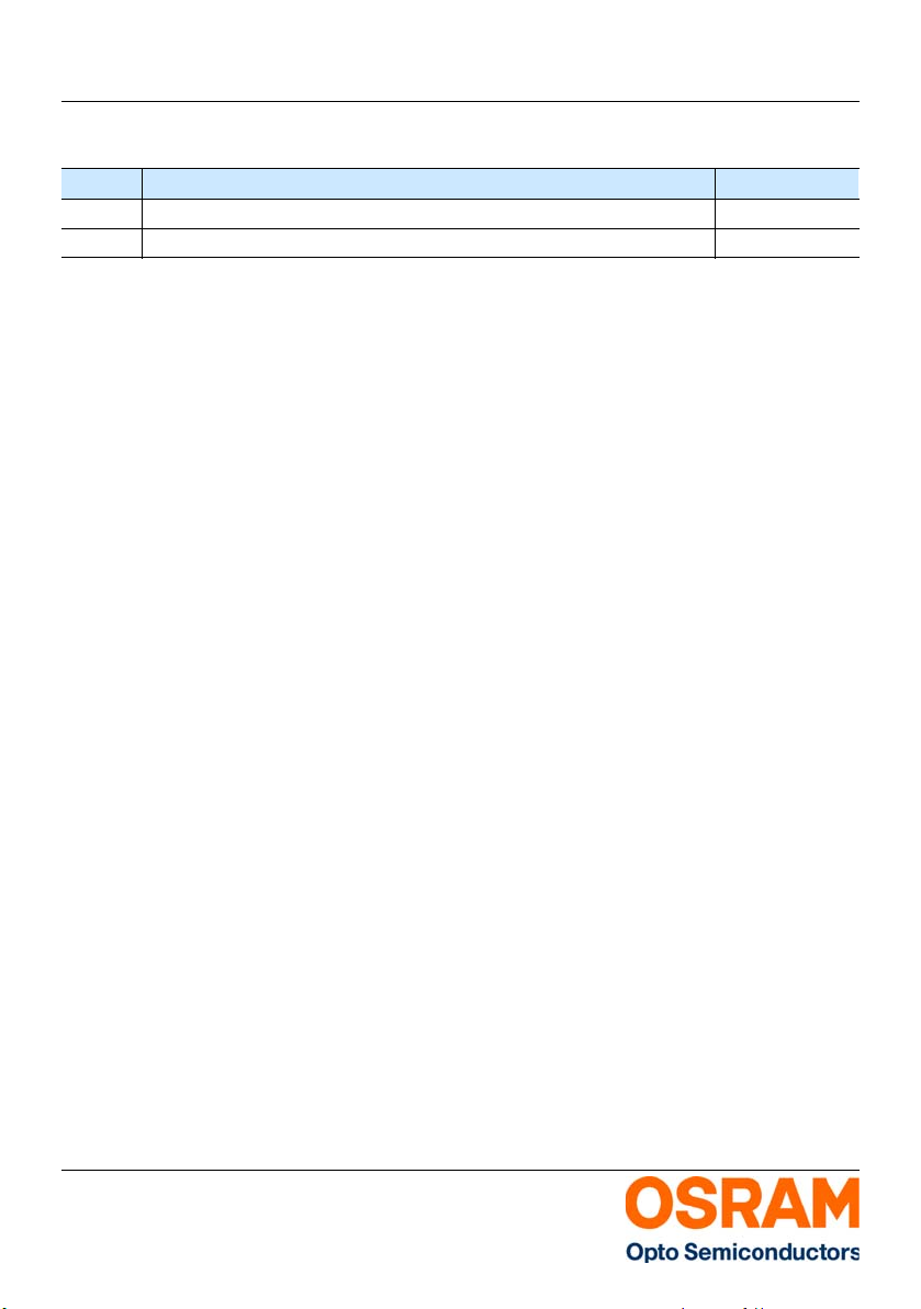
Version Subjects Date of change
2.0 OS-IN-2012-008 2012-05-02
3.0 OS-PCN-2013-015-A 2013-08-15
Disclaimer Disclaimer
Attention please!
The information describes the type of component and
shall not be considered as assured characteristics.
Terms of delivery and rights to change design reserved.
Due to technical requirements components may contain
dangerous substances.
For information on the types in question please contact
our Sales Organization.
If printed or downloaded, please find the latest version in
the Internet.
Packing
Please use the recycling operators known to you. We
can also help you – get in touch with your nearest sales
office.
By agreement we will take packing material back, if it is
sorted. You must bear the costs of transport. For
packing material that is returned to us unsorted or which
we are not obliged to accept, we shall have to invoice
you for any costs incurred.
Components used in life-support devices or
systems must be expressly authorized for such
purpose!
Critical components* may only be used in life-support
devices** or systems with the express written approval
of OSRAM OS.
*) A critical component is a component used in a
life-support device or system whose failure can
reasonably be expected to cause the failure of that
life-support device or system, or to affect its safety or the
effectiveness of that device or system.
**) Life support devices or systems are intended (a) to be
implanted in the human body, or (b) to support and/or
maintain and sustain human life. If they fail, it is
reasonable to assume that the health and the life of the
user may be endangered.
Bitte beachten!
Lieferbedingungen und Änderungen im Design
vorbehalten. Aufgrund technischer Anforderungen
können die Bauteile Gefahrstoffe enthalten. Für weitere
Informationen zu gewünschten Bauteilen, wenden Sie
sich bitte an unseren Vertrieb. Falls Sie dieses
Datenblatt ausgedruckt oder heruntergeladen haben,
finden Sie die aktuellste Version im Internet.
Verpackung
Benutzen Sie bitte die Ihnen bekannten Recyclingwege.
Wenn diese nicht bekannt sein sollten, wenden Sie sich
bitte an das nächstgelegene Vertriebsbüro. Wir nehmen
das Verpackungsmaterial zurück, falls dies vereinbart
wurde und das Material sortiert ist. Sie tragen die
Transportkosten. Für Verpackungsmaterial, das
unsortiert an uns zurückgeschickt wird oder das wir nicht
annehmen müssen, stellen wir Ihnen die anfallenden
Kosten in Rechnung.
Bauteile, die in lebenserhaltenden Apparaten und
Systemen eingesetzt werden, müssen für diese
Zwecke ausdrücklich zugelassen sein!
Kritische Bauteile* dürfen in lebenserhaltenden
Apparaten und Systemen** nur dann eingesetzt
werden, wenn ein schriftliches Einverständnis von
OSRAM OS vorliegt.
*) Ein kritisches Bauteil ist ein Bauteil, das in
lebenserhaltenden Apparaten oder Systemen
eingesetzt wird und dessen Defekt voraussichtlich zu
einer Fehlfunktion dieses lebenserhaltenden Apparates
oder Systems führen wird oder die Sicherheit oder
Effektivität dieses Apparates oder Systems
beeinträchtigt.
**) Lebenserhaltende Apparate oder Systeme sind für
(a) die Implantierung in den menschlichen Körper oder
(b) für die Lebenserhaltung bestimmt. Falls Sie
versagen, kann davon ausgegangen werden, dass die
Gesundheit und das Leben des Patienten in Gefahr ist.
2013-08-20 21
Page 22
Version 3.0 LW T673
Glossary Glossar
1)
Brightness: Brightness values are measured during
a current pulse of typically 25 ms, with an internal
reproducibility of ± 8 % and an ex panded uncertainty
of ± 11 % (acc. to GUM with a coverage factor of
k = 3).
2)
Reverse Voltage: Driving the LED in reverse
direction is suitable for short term application.
3)
Chromaticity coordina te groups: Chromaticity
coordinates are measured during a current pulse of
typically 25 ms, with an internal reproducibility of
± 0.005 and an expanded uncertainty of ± 0.01 (acc.
to GUM with a coverage factor of k = 3).
4)
Forwar d Voltage: The forward voltage is measured
during a current pulse of typically 8 ms, with an
internal reproducibility of ± 0.05 V and an expanded
uncertainty of ± 0.1 V (acc. to GUM with a coverage
factor of k = 3).
5)
Thermal Resistance: RthJA results from mounting
on PC board FR 4 (pad size 16mm² per pad)
6)
Thermal Resistance: Rth max is based on statistic
values (6σ).
7)
Typical Values: Due to the special conditions of the
manufacturing processes of LED, the typical data or
calculated correlations of technical parameters can
only reflect statistical figures. These do not
necessarily correspond to the actual parameters of
each single product, which could differ from the
typical data and calculated correlations or the typical
characteristic line. If requested, e.g. because of
technical improvements, these typ. data will be
changed without any further notice.
8)
Relative Brightness Curve: In the range where the
line of the graph is broken, you must expect higher
brightness differences between single LEDs within
one packing unit.
9)
Tolerance of Measure: Dimensions are specified
as follows: mm (inch).
1)
Helligkeit: Helligkeitswerte werden während eines
Strompulses einer typischen Dauer von 25 ms, mit
einer internen Reproduzierbarkeit von ± 8 % und
einer erweiterten Messunsicherheit von ± 11 %
gemessen (gemäß GUM mit Erweiterungsfaktor
k = 3).
2)
Sperrspannung: Die LED kann kurzzeitig in
Sperrrichtung betrieben werden.
3)
Farbortgruppen: Farbkoordinaten werden während
eines Strompulses einer typischen Dauer von 25 ms,
mit einer internen Reproduzierbarkeit von ± 0,005
und einer erweiterten Messunsicherheit von ± 0,01
gemessen (gemäß GUM mit Erweiterungsfaktor
k = 3).
4)
Durchlassspannung: Vorwärtsspannungen
werden während eines Strompulses einer typischen
Dauer von 8 ms, mit einer internen
Reproduzierbarkeit von ± 0,05 V und einer
erweiterten Messunsicherheit von ± 0,1 V gemessen
(gemäß GUM mit Erweiterungsfaktor k = 3).
5)
Wärmewiderstan d: RthJA ergibt sich bei Montage
auf PC-Board FR 4 (Padgröße 16mm² je pad)
6)
Wärmewiderstan d: Rth max basiert auf
statistischen Werten (6σ).
7)
Typische Werte: Wegen der besonderen
Prozessbedingungen bei der Herstellung von LED
können typische oder abgeleitete technische
Parameter nur aufgrund statistischer Werte
wiedergegeben werden. Diese stimmen nicht
notwendigerweise mit den Werten jedes einzelnen
Produktes überein, dessen Werte sich von typischen
und abgeleiteten Werten oder typischen Kennlinien
unterscheiden können. Falls erforderlich, z.B.
aufgrund technischer Verbesserungen, werden
diese typischen Werte ohne weitere Ankündigung
geändert.
8)
Relative Helligkeitskurve: Im gestrichelten
Bereich der Kennlinien muss mit erhöhten
Helligkeitsunterschieden zwischen Leuchtdioden
innerhalb einer Verpackungseinheit gerechnet
werden.
9)
Maßtoleranz: Maße werden wie folgt
angegeben: mm (inch).
2013-08-20 22
Page 23

Version 3.0 LW T673
Published by OSRAM Opto Semiconductors GmbH
Leibnizstraße 4, D-93055 Regensburg
www.osram-os.com © All Rights Reserved.
2013-08-20 23
 Loading...