


Series 255 Valve / 460i
Water Conditioning Control System
Installation, Operation and Maintenance Manual

Table of Contents
Introduction . . . . . . . . . . . . . . . . . . . . . . . . . . . . . . . 2
Series 255/460i Demand Control System
460i Electronic Demand System
Installation . . . . . . . . . . . . . . . . . . . . . . . . . . . . . . . . 5
Location Selection
Water Line Connection
Drain Line Connection
Brine Line Connection
Overflow Line Connection
Splicing Low Voltage Transfer Cord. . . . . . . . . . . . 6
Placing Conditioner Into Operation . . . . . . . . . . . . 6
Programming the 460i . . . . . . . . . . . . . . . . . . . . . . . 7
Manual Regeneration . . . . . . . . . . . . . . . . . . . . . . . 8
Adjustment of Brine Control . . . . . . . . . . . . . . . . . . 9 Removing the 255 Control Module for Servicing 10 Specification. . . . . . . . . . . . . . . . . . . . . . . . . . . . . . 11 Pressure Graphs . . . . . . . . . . . . . . . . . . . . . . . . . . 12 Control Valving Identification . . . . . . . . . . . . . . . . 12 Valve Disc Operation . . . . . . . . . . . . . . . . . . . . . . . 12 Flow Diagrams . . . . . . . . . . . . . . . . . . . . . . . . . . . . 12 Replacement Parts . . . . . . . . . . . . . . . . . . . . . . . . 14 Preventive Maintenance . . . . . . . . . . . . . . . . . . . . 18
Injector Screen and Injector
Water Meter
Troubleshooting . . . . . . . . . . . . . . . . . . . . . . . . . . . 19
Introduction
Series 255/460i Demand Control System
The Series 255/460i demand control system combines design simplicity with reinforced Noryl* construction to provide the user with an uncommonly reliable appliance. The inherent reliability of the system means a long life of efficient, trouble-free, uninterrupted soft water luxury.
Should maintenance become necessary, the Series 255 offers a unique “separation” capability illustrated in this manual.
Of interest to both the owner and the water conditioning dealer are the design and operation benefits detailed below.
Superior Design
•Fewer parts than any control system of comparable function and most controls of lesser function.
•Single synchronous electric motor provides all the power needed to turn the camshaft.
•460i timer utilizes a microprocessor to provide a time-proven logic analysis to initiate regeneration.
•Electrical wiring is factory assembled. System cannot be connected incorrectly.
•System indexes manually with or without power to any one of its service or regeneration positions. Readout on timer face plate indicates control valve position.
•No dynamic seals that could cause leakage through wear or fatigue.
•Control accepts Noryl or brass manifold or modular bypass valve without modification, offering complete versatility and easy plumbing for any installation.
•Brining control valve built into system eliminates need for an external brine valve.
•Automatic drain flow controller is incorporated into the system.
Superior Operation
•Direct acting system functions independently of water pressure. No pistons or diaphragms that require a minimum water pressure to operate.
•Five-cycle operation provides for downflow service, upflow backwash, downflow brining, downflow rinse, downflow purge, or fast rinse. A sixth position is included for timed refill of the brine tank.
•Valve discs are held closed by water pressure and therefore are leak tight. The sealing forces are increased as the water pressure is increased. Valve seats are in a vertical position, which is the design position least vulnerable to plugging.
•System operation cannot get out of phase or sequence. Control always returns to a fixed service position after regeneration regardless of where in the regeneration cycle it was started.
•Bypass water is automatically available during regeneration.
*Noryl is a trademark of General Electric Company
2

460i Electronic Demand System
The two key components of the 460i electronic demand system are the microprocessor, a miniature computer located on the circuit board, and a water meter located at the valve outlet. The flow of conditioned water through the meter generates electrical impulses that tell the computer the amount of water being used.
Every day, at 2:00 a.m., the past seven days’ water usage is statistically averaged to anticipate the amount of water that will be used the next day. The computer then determines if the water conditioner has enough remaining capacity to supply the next day’s needs. If not, the unit will regenerate.
If the water usage pattern changes, the computer automatically compensates for the change and regenerates only when needed. This results in higher operating efficiency and lower salt usage than a conventional conditioner operating on a fixed regeneration schedule.
Special Features
Memory Retention
During a power outage, all of the data in the microprocessor’s memory is stored in a special electronic chip called NOVRAM, Nonvolatile Random Access Memory. This data includes the time of day, water usage amounts, and the number of days since the last regeneration. When power is restored, the NOVRAM returns the data to the microprocessor and operation resumes as if an outage never occurred.
The time of day will be late by the length of the power outage. Most power outages are less than one minute in duration. Therefore, it may be months or years before the time display would require resetting. If an outage of one or more hours occurs, the time of day should be reset. No other reprogramming is necessary.
“Reserve” and High Water Usage
“Reserve” refers to the amount of soft water that may be needed for the next 24 hours. The microprocessor calculates how much soft water was used and adjusts the reserve capacity accordingly at the end of each day. As a result, the reserve is kept at a minimum for optimum economy. The reserve amount is calculated by multiplying the average past seven days’ usage
by 1.2. Regeneration decisions are based on the calculated reserve.
Self-Adjusting Reserve
The 460i is programmed to react to a sudden increase in water usage. If a day’s usage is more than double the current average, the computer anticipates that a second day of high usage is likely to occur. The high
usage amount will be used as the reserve when the 460i performs its regeneration computation.
Low or No Water Usage
The 460i is programmed to recognize a day of very little or no water usage as an abnormality. It will not use data from such a day to compute the average usage. For example, if the family is on vacation for a week, the prior average will be maintained. When household activity resumes, the 460i will operate as if the vacation had not occurred.
Design Reliability
Solid-state electronics assure many years of trouble-free performance. The metering system has only one moving part: the rotating turbine that measures water usage and generates electrical pulses that are continually counted by the microprocessor to determine the need to regenerate.
Time Display
The correct time will continually appear in the time display during normal conditioning operation. To change the hour display, press the TIME SET BUTTON until the present hour appears. The PM light will be on when the time is between 12:00 noon and midnight. The light is off during the AM hours.
Flow Indicator
The water flow indicator on the time display flashes whenever conditioned water is flowing through the valve. This allows an easy determination of proper meter operation.
Hardness and Capacity Settings
Once the hardness and capacity settings have been set, the information cannot be lost due to a power outage; reprogramming is not necessary.
Guest Cycle
An extra regeneration can be achieved at any time by depressing the pointer knob. It will take a few minutes for the regeneration to start. The unit will return to service in two hours. This feature is beneficial when you expect to use more than the normal amount of water, for example: guest visits, extra heavy laundry days, etc.
Programmable Calendar Override
The 460i controller has a unique feature that allows a calendar override of 1 to 15 days. This override will initiate a regeneration at the programmed interval if the water usage has not been enough to initiate regeneration.
3

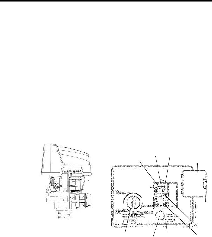
Control Module
Standard L-Lid
Cover
Figure 1
Tank Adapter Module
Optional Bypass
Brine Line Fitting Connection 1/4-inch NPT
Air Check
Inlet Connection 3/4-inch or 1-inch NPT or BSPT
Drain Connection 3/8-inch or 1/2-inch NPT or BSPT
Outlet Connection 3/4-inch or 1-inch NPT or BSPT
Tank Thread 2-1/2-inch - 8 Male
Figure 2
4
Installation
All plumbing must conform to local codes.
Inspect unit carefully for carrier shortage or shipping damage.
Location Selection
1.The distance between the unit and a drain should be as short as possible.
2.If it is likely that supplementary water treating equipment will be required, make certain adequate additional space is available.
3.Since salt must be added periodically to the brine tank, the location should be easily accessible.
4.Do not install any unit closer to a water heater than a total run of 10 feet (3 m) of piping between the outlet of the conditioner and the inlet to the heater. Water heaters can sometimes overheat to the extent they will transmit heat back down the cold pipe into the unit control valve.
Hot water can severely damage the conditioner. A 10-foot (3-m) total pipe run, including bends, elbows, etc., is a reasonable distance to help prevent this possibility. A positive way to prevent hot water from flowing from heat source to the conditioner, in the event of a negative pressure situation, is to install a check valve in the soft water piping from the conditioner. If a check valve is installed, make certain the water heating unit is equipped with a properly rated temperature and pressure safety relief valve. Also, be certain that local codes are not violated.
5.Do not locate unit where it or its connections
(including the drain and overflow lines) will ever be subjected to room temperatures under 34oF (1oC) or over 120oF (49oC).
6.Do not install unit near acid or acid fumes.
Water Line Connection
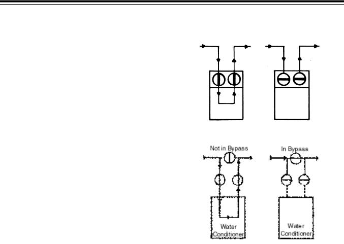
A bypass valve system must be installed since there will be occasions when the water conditioner must be bypassed for hard water or for servicing.
The most common bypass systems are the Autotrol® Series 256 bypass valve (Figure3) and plumbed-in globe valves (Figure4). Though both are similar in function, the 256 Autotrol bypass offers simplicity and ease of operation.
Not in Bypass |
In Bypass |
Water |
Water |
Conditioner |
Conditioner |
Figure 3 – Autotrol Series 256 Bypass Valve
Figure 4 – Typical Globe Valve Bypass System
Drain Line Connection
1.Ideally located, the unit will be above, and not more than 20 feet (6.1 m) from the drain. For such installations, using an appropriate adapter fitting (not supplied), connect 1/2-inch (1.3-cm) plastic tubing to the drain connection located on the control.
2.If the unit is located more than 20 feet (6.1 m) from drain, use 3/4-inch (1.9-cm) tubing for runs up to 40 feet (12.2 m).
3.If the unit is located where the drain line must be elevated, you may elevate the line up to 6 feet (1.8 m) providing the run does not exceed 15 feet (4.6 m) and water pressure at conditioner is not less than 40 psi (2.3 bar). You may elevate an additional 2 feet (61 cm) for each additional 10 psi (0.69 bar).
4.Where the drain line is elevated but empties into a drain below the level of the control valve, form a 7-inch (18-cm) loop at the far end of the line so that the bottom of the loop is level with the drain connection. This will provide an adequate siphon trap.
5.Where the drain empties into an overhead sewer line, a sink-type trap must be used.
5
Important: Never connect drain line into a drain, sewer line or trap. Always allow an air gap between the drain line and the wastewater to prevent the possibility of sewage being back-siphoned into conditioner.
transformer secondary cable to the mating socket on the bottom of the controller.
Be certain the transformer is plugged into a source that is not controlled by a wall switch and cannot be accidentally turned off.
Figure 5
Note: Standard commercial practices have been expressed here. Local codes may require changes to these suggestions.
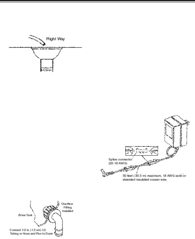
Splicing the Low Voltage
Transformer Cord
If it is necessary to extend the length of the transformer cord, an optional 15-foot (4.6-m) extension cord is available (P/N 1000907), or the cord may be spliced as follows:
1.Strip insulation from wire 5/16 inch (.8 cm) from wire end.
2.Insert stripped wire into barrel of connector and crimp. For best results, crimp twice per wire as shown in Figure7.
Splice connectors or extension wire is not supplied. They are available at hardware or electrical stores.
Brine Line Connection
It will be necessary to install the brine tube and connect the line to a fitting installed on the air check.
Be sure all fittings and connections are tight so that premature checking does not take place. Premature checking is when the ball in the air check falls to the bottom before all brine is drawn out of the brine tank. See Placing Conditioner into Service section.
Overflow Line Connection
To connect overflow, locate the hole on the side of the brine tank. Insert overflow fitting (not supplied) into tank and tighten with plastic thumb nut and gasket as shown (Figure6). Attach length of 1/2-inch (1.3-cm) I.D. tubing (not supplied) to fitting and run to drain. Do not elevate overflow line higher than 3 inches (7.6 cm) below bottom of overflow fitting.
Figure 6
Electrical Connection
12VAC:
The power supply transformer should have a minimum rating of 3 volt-amps. Connect the plug of the
Figure 7
Placing Conditioner into
Operation
After all previous steps have been completed, the unit is ready to be placed into operation. Follow these steps carefully:
1.Remove control valve cover (Figure 14).
Note: The following steps will require turning the pointer knob (Figure 9) to various positions. Insert a wide-blade screwdriver into arrow slot in pointer knob and press in firmly. With knob held in, rotate
COUNTERCLOCKWISE only until arrow or knob points to desired position. (Rotation is made much easier if you grasp the camshaft with your free hand and turn it at the same time.) Then permit knob to spring back out.
2.Insert screwdriver into slot in pointer knob (Figure9). Press in and rotate knob
6
COUNTERCLOCKWISE until arrow points directly to the word BACKWASH.
3.Fill resin tank with water.
A.With water supply off, place the bypass valve(s) into the “not in bypass” position.
B.Open water supply valve very slowly to approximately the 1/4 open position.
Important: If opened too rapidly or too far, resin may be lost. In this position, you should hear air escaping slowly from the drain line.
C.When all of the air has been purged from the tank and clear water begins to flow steadily from the drain, close main supply valve.
D.With the water supply off, let the unit stand for about five minutes. This will allow all trapped air to escape from the tank.
E.Proceed to step 4.
4.Add water to brine tank (initial fill). With a bucket or hose, add approximately four gallons (15 liters) of water to brine tank. If the tank has a salt platform above the bottom of the tank, add water until the level is approximately 1 inch (25 mm) above the platform.
SLOW RINSE position.
D.With the conditioner in this position, check to see if water is being drawn from the brine tank. The water level in the brine tank will recede very slowly. Observe for at least three minutes. If the water level does not recede or goes up, or if air enters the transparent air check chamber and the ball falls and seats, reference
Troubleshooting section.
E.Advance pointer knob COUNTERCLOCKWISE to CONDITIONED WATER.
F.Run water from a nearby faucet until the water is clear and soft.
Programming the 460i
Plug the wall mount transformer into a functioning electrical outlet that is not controlled by a switch. Plug the transformer plug into the transformer plug receptacle on the timer.
Note: If the included transformer cord is not long enough, a 15-foot (4.6-m) extension is available. See
Splicing the Low Voltage Transformer Cord section
of this manual.
Open the access door by pushing the raised tab on the door toward the left while pulling the tab out (Figure9).
255/460i shown with optional i-lid cover (PN 1000062)
Figure 8
5.Put into operation.
A.Open water supply valve slowly to full open position.
B.Carefully advance pointer knob
COUNTERCLOCKWISE to center of FAST RINSE/REFILL position and hold there until air check (Figure1) fills with water and water starts to flow through brine line into brine tank. Do not run for more than two minutes.
C.Advance pointer knob COUNTERCLOCKWISE until arrow points to the center of the BRINE/
Water Flow Indicator |
Hour Time Display |
PM Indicator |
Access Door |
|
Raised |
|
|
Tab |
|
|
Jumper |
|
Pointer Knob |
Transformer Plug |
|
Spare |
||
Time Set Button |
||
Receptacle |
||
|
Jumper |
Figure 9
Time of Day Setting
With the jumper on the set of pins next to the word TIME (Figure 10), set the time of day to the closest hour by pressing the black TIME SET button. PM hours are indicated by a light next to the letters PM on the display window.
7

Note: The use of a small needle nose pliers or tweezers will aid in moving the jumper.
Note: The unit is factory set to regenerate at 2:00 a.m. If you prefer to have the unit regenerate at an earlier or later time, simply set the current time of day accordingly. To have the unit regenerate at 4:00 a.m., two hours later, set the clock two hours earlier than the actual current time.
Hardness Setting
Move the jumper to the set of pins next to the word HARDNESS (Figure 11). Press the black TIME SET button until the correct hardness is displayed. The hardness range is from 1 to 99 grains per gallon.
To change water hardness stated in parts per million (PPM) to grains per gallon (GPG) use this formula:
Parts per Million = Grains per Gallon 17.1
Figure 10 |
Figure 11 |
Figure 12 |
Capacity Setting
Move the jumper to the set of pins next to the word CAPACITY (Figure 12). Press the black TIME SET button until the correct capacity value is displayed. The capacity range is 1 to 99 kilograins. Refer to the Suggested Salt Dial Settings table.
Return the jumper to the top set of pins next to the word TIME and replace the access door. The next three sets of pins are used for factory testing and are not used in normal operation. The jumper must NOT be left on any pins other than the top pair next to the word TIME. Otherwise, the unit may not function.
Note: A spare jumper is located on the bottom set of pins.
In the event that the hardness or capacity setting must be changed, simply follow the appropriate steps described above.
Calendar Override Setting
1.Disconnect power.
2.Place jumper on Pin A and reconnect power.
3.Move jumper to Pin B. A zero will appear, indicating zero days of calendar override. All 460i controllers are preprogrammed in this manner at the manufacturer.
4.Depress the black TIME SET button. The numbers will roll from “0” to “15.” Release the switch at the desired number of days for the calendar override. For example, releasing the switch at “10” would program a 10-day calendar override.
5.Disconnect power.
6.Place jumper back on TIME and reconnect power.
7.The calendar override program is maintained during power outages by the NOVRAM circuitry.
8.To remove the calendar override, follow the same steps above and program back to “0.”
Manual Regeneration
Electricity is used only to run the timer and to rotate the camshaft. All other functions are operated by water pressure. Therefore, in the event of a power outage, all the regeneration positions may be dialed manually by depressing the pointer knob with a straight blade screwdriver and turning COUNTERCLOCKWISE.
Manual time cycle:
•Backwash–14 minutes
•Brine/Slow Rinse–52 minutes
•Brine Refill–10 minutes
•Fast Rinse/Refill–6 minutes.
Do not exceed 10 minutes for the refill cycle as this will cause excessive salt usage during the next regeneration and possibly a salt residue in the softened water.
DO NOT advance the pointer knob directly to the conditioned water position (6 o’clock) after a manual regeneration or when servicing the conditioner. Advance it to just past the purge position, approximately 7 o’clock. The timer will then advance itself to the conditioned water position where the internal switch will turn the motor off. The internal switch will not be operated and the motor will continue to run if advanced directly to the conditioned water position.
If power fails during a conditioner regeneration, the cycle will be completed normally when the power is restored.
8
 Loading...