

Page 1
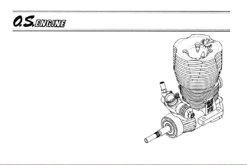
MAX-21VZ-B V-Spec
OWNER'S INSTRUCTION MANUAL
It is of
operate your engine, to read the general
'SAFETY INSTRUCTIONS AND WARNINGS'
section on pages 2-5 of this booklet and to strictly
adhere to the advice contained therein.
•Also, please study the entire contents of this
• Keep these instructions in a safe place so that
• It is suggested that any instructions supplied
vital importance, before attempting to
instruction manual, so as to familiarize yourself
with the controls and other features of the
engine.
you may readily refer to them whenever
necessary.
with the vehicle, radio control equipment, etc.,
are accessible for checking at the same time.
Page 2

CONTENTS
SAFETY INSTRUCTIONS AND
WARNINGS ABOUT YOUR O.S.
ENGINE CONSTRUCTION---------------- 6
NOTES WHEN APPLYING AN ELECTRIC
STARTER
ABOUT THE ENGINE-------------------- 8
BEFORE STARTING-------------------9-11
BASIC
CARBURETOR CONTROLS---------------12
GLOWPLUG---------------------------13
INSTALLATION
ACCESSORIES------------------------ 14
INSTALLATION------------------------- 15
-----------------------------
ENGINE PARTS
------------------
OF THE STANDARD
ENGINE - - - - 2-5
7
11
STARTING THE ENGINE & RUNNING-IN---16-19
FINAL ADJUSTMENT------------------20-22
CARBURETOR CLEANLINESS-------------22
CARE AND MAINTENANCE ------------ 23-24
CHECKING THE ENGINE ----------------- 24
GUARANTEE-----------------------25
TROUBLE SHOOTING-----------------26-29
ENGINE EXPLODED VIEW & PARTS LIST
CARBURETOR EXPLODED VIEW &
PARTS LIST-------------------------32-33
O.S. GENUINE
THREE VIEW DRAWING------------------36
1
PARTS & ACCESSORIES
- - - - 34-35
- - - 30-31
Page 3

SAFETY INSTRUCTIONS AND WARNINGS ABOUT YOUR O.S. ENGINE
Remember that your engine is not a "toy", but a highly efficient internalcombustion machine whose power is capable of harming you, or others, if it is
misused.
As owner, you, alone, are responsible for the safe operation of your engine, so act
with discretion and care at all times.
If at some future date, your O.S. engine is acquired by another person, we would
respectfully request that these instructions are also passed on to its new owner.
• The advice which follows applies basically to ALL MODEL ENGINES and is
grouped under two headings according to the degree of damage or danger
which might arise through misuse or neglect.
WARNINGS
These cover events which
might involve serious (in
extreme circumstances, even
fatal) injury.
NOTES
These cover the many other
possibilities, generally less obvious
sources of danger, but which, under
certain circumstances, may also
cause damage or injury.
2
Page 4
WARNINGS
Model engine fuel is poi-
sonous. Do not allow it to
come into contact with the
eyes or mouth. Always store
it in a clearly marked container and out of the reach
of children.
Model engine fuel is also
highly flammable. Keep it
away from an open flame,
excessive heat, sources of
sparks, or anything else
which might ignite it. Do not
smoke or allow anyone else
to smoke, near to it.
Never operate your engine in an enclosed space. Model engines, like
automobile engines, exhaust deadly
carbon-monoxide. Run your engine
only in an open area.
Model engines generate
considerable heat. Do not
touch any part of your
engine until it has cooled.
Contact with the muffler
(silencer), cylinder head
or exhaust header pipe, in
particular, may result in a
serious burn.
3
Page 5
NOTES
This engine is intended for model cars.
Do not attempt to use it for any other
purpose.
Mount the engine in your model
securely, following the manufacturers'
recommendations, using appropriate
screws and locknuts.
Install an effective silencer (muffler).
Frequent close exposure to a noisy
exhaust (especially in the case of the
more powerful highspeed engines)
may eventually impair your hearing
and such noise is also likely to cause
annoyance to others over a wide area.
The wearing of safety glasses is also
strongly recommended.
Take care that the glowplug clip or
battery leads do not come into contact
with rotating parts. Also check that the
linkage to the throttle arm is secure.
For their safety, keep all onlookers
(especially small children) well back
(at least 20 feet or 6 meters) when
preparing your model for running.
4
Page 6

NOTES
To stop the engine, fully retard the
throttle stick and trim lever on the
trans-mitter, or, in an emergency, cut
off the fuel supply by pinching the fuel
delivery line from the tank.
Warning! Immediately after a glowplugignition engine has been run and is still
warm, conditions sometimes exist
whereby it is just possible for the engine
to abruptly restart if it is rotated over
compression WITHOUT the glowplug
battery being reconnected.
5
Page 7
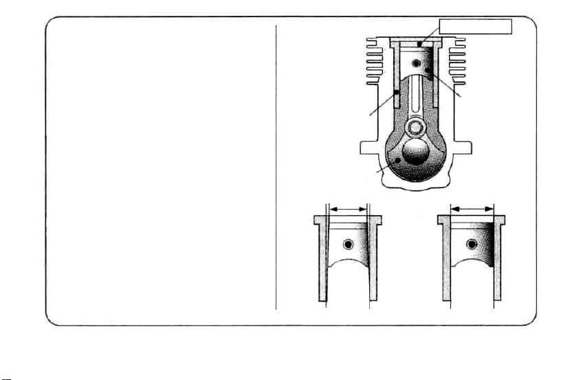
ENGINE CONSTRUCTION
With this engine, the piston will
feel tight at the top of its stroke
(TDC) when the engine is cold.
This is normal. The cylinder bore
is a little tapered. The piston and
cylinder are designed to achieve
a perfect running clearance
when they reach their running
temperatures.
Around TDC
Piston
Cylinder Liner
Crankshaft
A little tapered
When the engine is cold. When the engine is hot.
6
Page 8
NOTES WHEN APPLYING
AN ELECTRIC STARTER
Do not over-prime. This could
cause hydraulic lock and damage
the engine on application of the
electric starter.
If over-primed, remove glowplug,
close needle-valve and apply
starter to pump out surplus fuel.
Cover the head with waste to
prevent pumped out fuel coming
into your eyes. NOTE
As delivered, the engine has its
carburetor lightly fit into its intake.
Secure it changing its angle
according to the car chassis.
7
Page 9
ABOUT THE ENGINE
The MAX-21 VZ-B V-Spec is a high performance 3.5cc class power unit for oneeight-scale radio-controlled 'off-road' or
'buggy' cars. It has been expressly designed for racing competitions.
T-type plug (turbo plug) design improves
the power, fuel consumption and durabili-
ty.
The new 21 C carburetor is supplied with
8mm and 9mm dia. reducers to manage
different course conditions.
Standard accessories
Glow Plug P3 T-type head (Turbo head)
1piece
(Hot Type)
Cylinder-head gasket (0.1mm) 1 sheet
Exhaust Seal Ring 1 piece
Carburetor Reducer 8mm (Red) 1 piece
(w/ "0" Ring)
Dust Cap 03,016,018 every Ipiece
8
Page 10
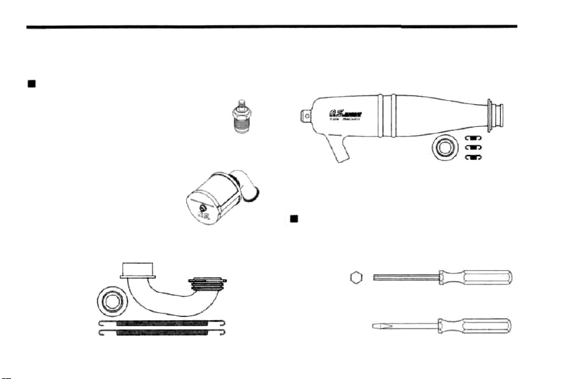
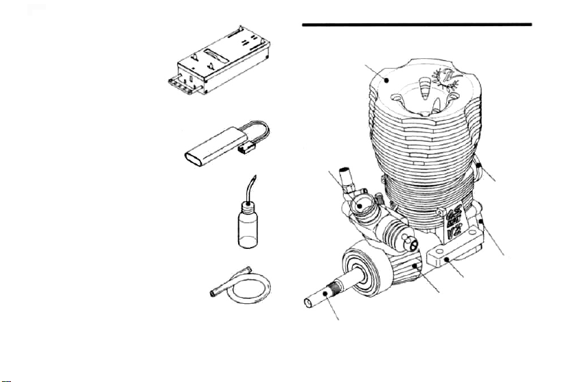
BEFORE STARTING
Tools, accessories, etc.The following items are
necessary for operating the engine.
Optional Extras
GLOW PLUG T-Type (Turbo Plug)
P3 is supplied with the engine. As
replacement, suggested O.S. plugs are
P3 and P6.
SUPER AIR CLEANER 203 ASSEMBLY
This is a heavy-duty wet type
air cleaner designed specifically
tor 3.5cc 'off-road' model car
engines.
T-2050 EXHAUST HEADER PIPE ASSEMBLY
This is designed to use with the T-2050
Tuned Silencer
T-2050 TUNED SILENCER ASSEMBLY
This is designed specifically for 3.5cc 'off-road'
model car engines.
T-2050 TUNED SILENCER COMPLETE SET
This is a set of T-2050 Tuned Silencer and T2050 Exhaust Header Pipe Assembly.
TOOLS
HEX WRENCH
Necessary for engine installation.
1.5mm, 2mm, 2.5mm, 3mm opposite side
SCREWDRIVER
Necessary for carburetor adjustments.
No.1,No.2,etc
9
Page 11
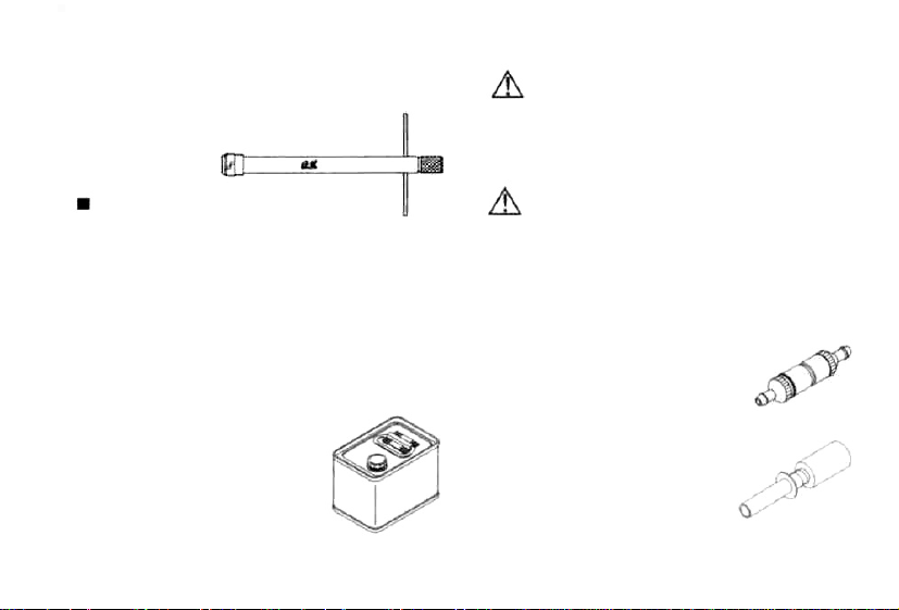
LONG SOCKET WRENCH WITH PLUG GRIP REMINDER!
Recommended for easy removal and
replacement of the angled and recessed
glowplug, the O.S.Long Socket Wrench
incorporates a special grip.
Model engine fuel is poisonous. Do
not allow it to come into contact with
the eyes or mouth. Always store it in a
clearly marked container and out
the reach of children.
Items necessary for starting
FUEL
Generally, it is suggested that the user selects a fuel
that is commercially available for model two-stroke
engines and contains 10-30% nitromethane. As a
starting point, we recommend a fuel containing 20%
nitromethane, changing to a fuel containing more
nitro if necessary. When the brand of fuel is
changed, or the nitro content increased, it is
advisable to repeat the running-in procedure
referred to in the RUNNING-IN paragraphs. Please
note that with high-nitro fuels,
although power may be increased
for competition purposes,
glowplug elements do not last as
long and engine life will be
shortened.
Model engine fuel is also highly
flammable. Keep it away from open
flame, excessive heat, sources of
sparks, or anything else which might
ignite it. Do not smoke or allow anyone
else to smoke, near to it.
FUEL FILTER
To fit in the fuel line between fuel
tank and carburetor to prevent
dust coming into the carburetor.
GLOWPLUG IGNITER
Commercialy available handy
glowplug heater in which the
glowplug battery and battery
leads are integrated.
10
of
Page 12
STARTER BOX
For starting the engine.
7.2V BATTERIES FOR STARTER BOX
Batteries for starter box.
Select according to the
starter box used. Be sure to
full charge before using.
FUEL PUMP
For filling the fuel tank, a simple,
polyethylene "squeeze" bottle,
with a suitable spout, is required.
SILICONE FUEL LINE
Heatproof silicone tubing of
approx. 5mm o.d. and 2mm i.d.
is required for the connection
between the fuel tank and
engine.
BASIC ENGINE PARTS
Heatsink Head
Carburetor
Type 21 C
Exhaust
Cover Plate
Mounting Lugs
Crankcase
Crankshaft
11
Page 13

CARBURETOR CONTROLS
Carburetor Reducer
Needle Valve
Mixture Control Valve
Assembly Screw
Throttle Stop
Screw
Metering Needle
Thermo Insulator
Four adjustable controls are provided on
this carburetor.
The Needle-Valve:
For adjusting the mixture strength when the
throttle is fully open.
The Mixture Control Screw:
For changing the mixture strength
speed and acceleration. (Do not
screw more than one turn.)
The Metering Needle:
For adjusting the mixture strength at partthrottle and idling speeds, to obtain steady
idling and smooth acceleration to mid
speeds.
The Throttle Stop Screw:
For setting the minimum idling speed:
NOTE: Readjustment may be necessary,
occasionally to allow for changes in fuel
formula gear ratio or clutch engagement
point.
12
at mid
rotate the
Page 14

GLOWPLUG
Since the compatibility of glowplug and fuel
may have a marked effect on performance and
reliability, it may be worthwhile to choose the
R/C type plug found most suitable after
tests. Recommended O.S. plugs are P3 and P6.
Carefully install plug finger-tight, before final
tightening with the correct size plug wrench.
The role of the glowplug
With a glowplug engine, ignition is initiated by the
application of a 1.5-volt power source. When the
battery is disconnected, the heat retained within the
combustion chamber remains sufficient to keep the
plug filament glowing, thereby continuing to keep the
engine running. Ignition timing is 'automatic' : under
reduced load, allowing higher rpm, the plug becomes
hotter and, appropriately, fires the fuel/air charge
earlier; conversely, at reduced rpm, the plug become
cooler and ignition is retarded.
Glowplug life
Particularly in the
engines, glowplugs must be regarded as expendable
items. However, plug life can be extended and engine
performance maintained by careful use, i.e.:
Install a plug suitable for the engine.
Use fuel containing a moderate percentage of
nitromethane unless more is essential for racing
events.
Do not run the engine too lean and do not leave the
battery connected while adjusting the needle.
When to replace the glowplug
Apart from when actually burned out, a plug may
need to be replaced because it no longer delivers its
best performance, such as when:
Filament surface has roughened and turned white.
Filament coil has become distorted.
Foreign matter has adhered to filament
body has corroded.
Engine tends to cut out when idling.
Starting qualities deteriorate.
13
case of very high performance
or plug
Page 15

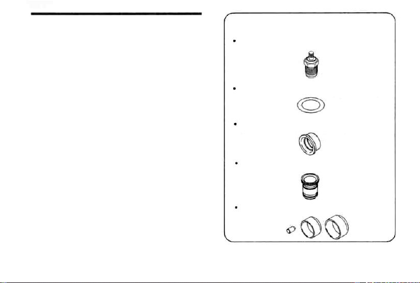
INSTALLATION OF THE STANDARD ACCESSORIES
Fitting the glow plug. Insert P3 plug supplied
into heatsink-head carefully, making sure that
it is not cross-threaded before tightening firmly.
(All the O.S. T-Type plugs including the P3 are
not supplied with a washer.)
Install the exhaust seal
ring supplied.
Glowplug
Exhaust
Seal Ring
Fitting the carburetor reducer
Replace the reduce according to the course
conditions.
9mm (Blue)
Fitted with the carburetor when leaves the factory. Suitable for high speed (wide) and flat
course which requires power.
8mm
(Red)
Supplied with the engine. Replace when required. Suitable for technical (narrow) and
bumpy course and when less fuel consumption
is more important.
The engine is fit with one each of 0.1mm and 0.2mm
cylinder-head gasket when it leaves the factory.
Another 0.1mm head gasket is supplied with the
engine. You may add it at initial running-in, when a
glow plug tends to burn out due to high temperature
and / or high humidity or when you prefer fuel
economy to power.
INSTALLATION OF THE DUST CAP SET
In case engine is kept, an exhaust port, a carburetor,
etc. are equipped and penetration of the foreign
substance inside engine is prevented.
14
Page 16

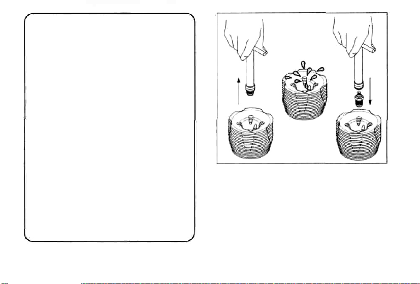
INSTALLATION OF THE CARBURETOR
As delivered, the engine has its carburetor lightly
installed in the intake boss. Secure it as follows.
1. Loosen the retainer screw, rotate the
carburetor to its correct position and make
sure that it is pressed well down into the
intake boss, compressing the rubber gasket,
before retightening screw.
2. Rotate the retainer screw gently until it
stops, then tighten a further 120-180 degrees.
Do not overtighten the screw as this will
damage the carburetor body.
ENGINE INSTALLATION
Make sure that the vehicle's engine mounting
surfaces are level and in the same plane. Poor
installation may cause distortion of the
crankcase, bearings, etc., resulting in erratic
running and loss of performance.
The recommended screws for securing the
engine are 3mm or 4-40 steel Allen hexagon
socket type.
If existing holes in the engine mount do not align
perfectly with engine mounting lugs, enlarge
them slightly with a needle-file so that screws are
in alignment with the mounting holes.
Rotate the retainer nut
gently until it slops.
Tighten a further
120-180 deg.
15
Do not allow bottom
of crankcase to
touch chassis.
Chassis
Chamfer inside edges of bearers.
Page 17

STARTING THE ENGINE & RUNNING-IN ("Breaking-in")
For long life and high performance, every
engine needs to be 'run-in' or 'broken-in'. With
care, running-in of the MAX-21VZ-B V-Spec
can be carried out with the engine installed in
the vehicle. Be sure to install the air-cleaner on
the carburetor and use a muffler-pressurized
fuel system.
The following procedure is suitable for these
engines when the O.S. T-2050 tuned silencer
and a fuel containing up to 30% nitromethane
are used.
Fill the tank completely with fuel.
Fuel Pump
Fuel Tank
Temporarily remove the glowplug to
that it glows bright red when energized.
Element glows when energized.
Replace the plug when the
element does not glow or is
burnt out.
Glow Plug Igniter
16
check
Pliers
Page 18

Turn the needle-valve clockwise slowly until
it stops. This is the fully closed position.
Do not force to turn further.
Open the Needle-Valve 3 turns from the fully
closed position.
Switch on the transmitter and receiver and
set the throttle very slightly open from the
idling position.
Turn the engine with starter box to draw the
fuel into the engine.
Needle Valve
Open
Throttle opening at idling
approx 0.3-0.5mm
Close
Note:
Throttle opening at idling should be
checked before fitting an air cleaner.
Starter Box
Deliver fuel into the carburetor.
Fuel
Fuel tank side
17
Page 19

Now connect glowplug battery lead to heat
the plug filament and start the engine.
Glow Plug Igniter
Air Cleaner
Starter Box
Attention:
It is vitally important to set the
throttle at the correct position
before starting the engine. If the
engine is allowed to run with the
throttle too far open under "no load" conditions
(i.e. with the driving wheels not in contact with
When the engine starts,
first allow it to operate in
short runs at the very rich
starting settings, with the
glowplug battery still
connected and the driving
wheels clear of the ground.
The rich mixture will, under
these conditions, provide
adequate lubrication and
cooling, indicated by
profuse smoke from the
exhaust.
Next, disconnect
the
glowplug battery and
try running the car on the track. If the engine
stalls, open the throttle fractionally, but try to
keep the engine running as rich as possible:
if it stops because of being excessively overrich, close the Needle-Valve 30° and try
again.
18
Page 20

Run the car on the track until one tank of fuel
has been consumed, then close the NeedleValve 30° and run the car for another full
tank of fuel. Repeat this procedure until 1/2
gallon of fuel have been consumed, during
which time the throttle may be opened for
brief bursts of increased power.
The position of the needle-valve
Needle
when starting the engine.
Close the needle-valve approx.
30° after running the vehicle tor
one full tank of fuel.
Repeat this procedure several
times.
Note:
If the engine should need to be disassembled (e.g. for cleaning or minor parts replacement), it is advisable to return the needle-valve to the original rich, starting setting and check whether further running-in
time is required before the car is raced
again. In the event of any major working
parts (e.g. piston/cylinder liner assembly)
being replaced or the fuel being changed,
especially to high nitro fuel, the complete
running-in should be repeated.
To stop the engine, close the throttle to
idling speed, then shut it off completely with
the trim lever on the transmitter. To cut off
the fuel supply, pinch the fuel delivery tube
to the carburetor.
Air Cleaner
Fuel
Warning!
Do not touch rotating parts, engine and silencer when stopping the engine as they
become very hot, and contact with them
may result in a serious burn.
19
Page 21

FINAL ADJUSTMENT
Final adjustment should be carried out only after
the running-in has been completed.
Needle Valve
Needle Valve
Open
Close
Metering Needle
Metering Needle
Open
Close
Run the vehicle (with throttle fully open) over
the longest available straight course, in order
to observe the model's speed. Next return
the car to the starting point, close the NeedleValve 30° and repeat the run, taking note of
the improvement in performance.
Continue with further runs, gradually
reducing the Needle-Valve setting and
aiming to achieve the highest straight-line
speed. Remember, however, that, if the
Needle-Valve is shut down too far, the
engine will overheat and, accompanied by
visibly diminished exhaust smoke, the model
will lose speed. At this point, throttle down
immediately, stop the vehicle and reopen the
Needle-Valve 45-90° .
More fuel Less fuel
More fuel
Less fuel
20
Page 22

With the engine running, close the throttle
and allow it to idle for about five seconds,
then reopen the throttle fully. If, at this point,
the engine puffs out an excessive amount of
smoke and the vehicle does not accelerate
smoothly and rapidly, it is probable that the
idling mixture is too rich. In this case, turn
the Metering Needle clockwise 45-90°. If, on
the other hand, the engine tends to speed up
momentarily and then cut out abruptly when
the throttle is opened, the idling mixture is
too lean. Correct this by turning the Metering
Needle counter-clockwise 45-90°.
NOTE:
Metering Needle adjustment should be
made in steps of not more than 45-90°,
carefully checking the effect.on throttle
response, of each small adjustment.
Carry out adjustments patiently, under actual
running conditions, until the engine responds
quickly and positively to the throttle control.
Warning!
Mixture adjustments (whether via the
Metering Needle, or the Needle-Valve)
cannot be made accurately under 'no-load'
conditions, which, in any case, are not
advised, since such operation carries the
risk of seriously damaging the engine
through over-revving and overheating.
With the optimum mixture control position,
light smoke is visible during high speed
running,and the engine rpm increases
smoothly during acceleration. Remember
that, if the engine is operated with the fuel/air
mixture slightly too lean, it will overheat and
run unevenly. As with all engines, it is
advisable to set both the needle-valve and
metering needle very slightly on the rich side
of the best rpm setting, as a safety measure.
If the engine runs too fast with the throttle
closed, the throttle stop screw should be
turned counter-clockwise to allow the throttle
opening to be reduced.
21
Page 23

Finally, beyond the nominal break-in period,
a slight readjustment toward a leaner needle
setting may be required to maintain
maximum performance.
CARBURETOR CLEANLINESS
The correct functioning of the carburetor
depends on its small fuel orifices remaining
clear.
REALIGNMENT OF METERING NEEDLE
MIXTURE CONTROL VALVE
In the course of making carburetor
adjustments, it is just possible that the Metering
Needle and the Mixture Control Valve may be
inadvertently screwed in or out too far and
thereby moved beyond its effective adjustment
range.
The basic positions can be found by rotating
the Metering Needle until its slotted head is
flush with the ball link body.
AND
Carburetor Body
Carburetor Body
22
Slide Valve
Ball Link
Rotate the Metering
Needle until its slotted
head is flush with the
ball link body. This is the
standard position.
Metering Needle
First rotate the Mixture
Control Valve until its slotted
head is flush with the
carburetor body. Then screw
the valve in exactly 1 turn.
This is the standard position.
Mixture Control Valve
Page 24

CARE AND MAINTENANCE
1.The minute particles of foreign matter, that are
present in any fuel may, by accumulating and
partially obstructing fuel flow, cause engine
performance to become erratic and unreliable.
O.S. 'Super-Filters' (large and small) are available,
as optional extras, to deal with this problem.
One of these filters installed to the pickup tube
inside your refueling container, will prevent the entry
of foreign material into the fuel tank. It is also
recommended that a good in-line filter be installed
between the tank and carburetor.
2. Do not forget to clean the filters regularly to remove
dirt and lint that accumulate on the filter screens.
Also, clean the carburetor itself occasionally.
3. At the end of each operating session, drain out any
fuel that may remain in the fuel tank.
Afterwards,energize the glow-plug and try to restart
the engine, to burn off any fuel that may remain
inside the engine. Repeat this procedure until the
engine fails to fire. Do this while the engine is still
warm.
4. Then, inject some after-run oil into the engine, and
rotate the engine with an electric starter for 4 to 5
seconds to distribute the oil to all the working
parts.
Note:
Do not Inject after-run oil Into the carburetor as
this may cause the 0-rlngs inside the carburetor
to deteriorate. These procedures will reduce the
risks of starting difficulties or corrosion after a
period of storage.
5. Finally, when cleaning the exterior of the engine,
use methanol or kerosene. Do not use gasoline or
any solvent that might damage the silicone fuel
tubing.
Caution:
The rear crankshaft bearing of this engine uses a
special plastic retainer. If the front housing needs
to be heated to remove or replace the bearing, do
not allow the bearing to exceed 120"C (248'F),
otherwise it may be damaged and rendered
unserviceable.
23
Page 25

Fitting Dust
When storing the engine, fit it to exhaust
port, carburetor, etc. to prevent dust entering
inside the engine.
Caps
CHECKING THE ENGINE
Engine will not develop normal performance
after long time running due to wearing of parts.
It is suggested to replace necessary parts when
the following symptoms are detected.
Engine sound changes and easily overheats.
Power has dropped extremely.
Idling is unstable and/or engine tends to stop
at idling.
In most cases, ball bearings, cylinder & piston
assembly, connecting rod and/or crankcase have
become worn out or abnormal. Check the
parts carefully and replace them if necessary.
24
Page 26

GUARANTEE
This engine is constructed from the very best
materials available and to the very highest
engineering standards, using the most advanced
precision machinery. However, the extremely high
stresses imposed by car racing operation under very
severe conditions, as well as stresses which are
exacerbated by the use of powerful fuels containing
very high concentrations of nitromethane, constitute
hazards which are beyond a manufacturer's control.
Accordingly, we regret that it is not possible to extend
our usual warranty terms to this particular engine -i.e.
no guarantee is offered against material wear, or
damage resulting therefrom, in actual use.
25
Page 27

TROUBLE SHOOTING
Engine fails to fire.
Fuel tank is empty.
Fuel not reaching the engine.
Glowplug element is burnt out.
Glowplug battery discharged
Clogged fuel filter
Air cleaner and silencer inside is dirty.
Over priming
Fuel tubing is disconnected.
Fuel tubing is kinked, split or has a hole.
Incorrect carburetor settings
Incorrect servo linkage
Reverse rotating direction of starter box.
Fill the tank with fuel and repeat
Priming procedure.
Replace glowplug.
Recharge or replace the battery.
Clean or replace fuel filter.
Replace cleaner element and clean inside silencer.
Remove glowplug and pump excess fuel.
Connect fuel tubing securely.
Check the tubing carefully and replace if necessary.
Return the metering needle
and mixture control valve to basic position.
Re-linkage after setting servo at neutral.
Mare sure it rotates counter clockwise seen
from crankshaft side.
26
Page 28

Engine fires intermittently but does not run.
Insufficient fuel in the tank.
Deteriorated glowplug
Clogged fuel filter
Air cleaner and silencer inside is dirty.
Engine overheated
Incorrect clutch release
Too immediately disconnecting plug battery
Fuel in the tank extremely bubbled
Fill the tank with fuel.
Replace glowplug.
Clean or replace fuel filter.
Replace cleaner element and clean inside silencer.
Wait until engine is cooled.
Adjust the tension of clutch spring.
Do not disconnect plug
battery and wait until
r.p.m. become stable.
Fit 0 rings to the tank screws to
prevent bubbles.
27
Page 29

Unstable idling
Unsuitable glowplug
Unsuitable fuel
Extremely light flywheel
Silencer is disconnected or has play
Not reaching expected peak r.p.m.
Insufficient warming up or running-in.
Silencer or manifold is not securely connected
or disconnected.
Fuel tubing from tank to is split or broken.
Use suggested glowplug in the instructions.
Do not use extremely high nitro or low oil fuel.
Add suitable load.
Install silencer securely.
Set the needle only after warming up.
Complete running-in.
Replace seal ring.
Check the connections
and secure them.
Replace the tubing.
28
Page 30

Poor response
Deteriorated glowplug
Incorrect carburetor settings
Incorrect setting of transmitter Exponential function.
Poor r.p.m. drop
Too much throttle opening at idling.
Incorrect carburetor fitting
Replace glowplug.
Readjust low r.p.m. range with metering
needle and mixture control valve.
Check the transmitter setting.
Close metering needle to adequate position
to lower idling r.p.m.
Fit carburetor securely.
29
Page 31

ENGINE EXPLODED VIEW
CM3X18
1
2
3
4
6
6
12
Screw
5
7
N-Round
14
13
Head Screw
8
9
C.M2.6X18
10
11
*Type of screw C—Cap Screw M--0val Fillister-Head Screw
F-Flat
Head
15
S-Set
17
C.M2.6X7
16
Screw
Page 32

ENGINE PARTS LIST
No.
Code No.
1 22105000
2 22105100
3 123764010
4
22103010
5
23906000
6
23817000
7
23755000
8
23818050
9
23715000
10
23981700
11
23731000
12
23751010
13
23730010
14
22102000
15
23764020
16
23757000
17
23763010
71641300
22826140
71533000
22884250
The
specifications are subject to alteration for improvement without notice.
Outer Head
Inner Head
Head Gasket (2pcs.)
Cylinder & Piston Assembly
Piston Pin
Piston Pin Retainer (2pcs.)
Connecting Rod
Carburetor Complete (Type 21 C)
Carburetor Sealing Gasket
Carburetor Retainer Assembly
Crankshaft Ball Bearing (Front)
Crankcase
Crankshaft Ball Bearing (Rear)
Crankshaft
Cover Gasket
Cover Plate
Screw Set
Glow Plug T-P3
Exhaust Seal Ring
Carburetor Reducer 8mm (RED) w/ "0" Ring (2pcs.)
Dust Cap Set ( 3mm, 16mm, 18mm)
Description
Page 33

CARBURETOR EXPLODED VIEW
* Type of screw
C. Cap Screw M Oval Fillister-Head Screw
F.FIat Head Screw N. Round Head Screw S.Set Screw
32
Page 34

CARBURETOR PARTS LIST
No.
Code No.
1
23781600
1-1
46066319
1-2
22781800
2
23618190
2-1
23618197
2-2
46066319
2-3
23618194
2-4
23818176
3
71533010
4
23818500
5
23818130
6
23781200
7
23818340
7-1
27881820
8
22884220
9
23781400
10
23781110
11
29015019
12
23818190
The specifications are subject to alteration for improvement without notice.
Mixture Control Valve Assembly
Needle Valve Assembly
Carburetor Reducer 9mm (BLUE) w/ "0" Ring (2pcs.)
Throttle Stop Screw
Carburetor Body (w/Thermo Insulator)
Slide Valve
Metering Needle Assembly
Dust Cover
Ball Link No.3
Thermo Insulator
Carburetor Rubber Gasket
Carburetor Sealing Washer
Description
"0" Ring (L) (2pcs.)
"0" Ring (S) (2pcs.)
Needle Assembly
"0" Ring (2pcs.)
Needle Holder Assembly
Fuel Inlet (No.9)
"0" Ring (2pcs.)
33
Page 35

O.S. GENUINE PARTS & ACCESSORIES
GLOWPLUG
P3 P6
(71641300) (71641600)
T-2050 TUNED SILENCER ASSEMBLY
(72106060)
T-2050 Tuned Silencer Body
(72106061)
Pressure Nipple
(72106041)
Exhaust Seal Ring (2pcs.)
(22826140)
Joint Spring (3pcs.)
(72106042)
T-2050 EXHAUST HEADER PIPE ASSEMBLY
(72106150)
Exhaust Header Pipe
(72106155)
Header Pipe Spring (2pcs.)
(72101272)
Exhaust Seal Ring (2pcs.)
(22826140)
T-2050 TUNED SILENCER
COMPLETE SET
(72106070)
T-2050
Tuned Silencer
(72106060)
Assembly
T-2050
Exhaust Header Pipe Assembly
(72106150)
The specifications are subject to alteration tor improvement without notice.
34
Page 36

O.S. GENUINE PARTS & ACCESSORIES
T-2030 TUNED SILENCER
(72106030)
21 RZ
EXHAUST HEADER PIPE
(72101270)
SUPER JOINT TUBE 21
(72106300)
DUST CAP SET
3mm
(5pcs.) (73300305)
8mm (3pcs.) (73300812)
16mm (3pcs.) (73301512)
18mm
(3pcs.) (73301812)
SUPER AIR CLEANER 203
(72413000)
203 Filter Element (4pcs.)
(72413200)
CRANKSHAFT CLAMP
1521
(71530200)
The specifications are subject to alteration for improvement without notice.
35
EXHAUST SEAL RING
(22826140) (2pcs.)
CAP SCREW SET
M2.6x7(10pcs.)
(79871020)
LONG SOCKET WRENCH
WITH PLUG GRIP
(715210001
Page 37

THREE VIEW DRAWING
SPECIFICATIONS
Displacement
Bore
Stroke
Practical R.P.M.
Power output
Weight
3.46cc(0.211cu.in.)
16.6mm (0.654in.)
16.0mm (0.630in.)
3,000-40.000 r.p.m.
2.48ps / 33.000
360g (12.7oz.)
r.p.m.
Dimensions (mm)
36
Page 38

6-15 3-Chome Imagawa Higashisumiyoshi-ku
Osaka 546-0003, Japan TEL. (06) 6702-0225
URL: http://www.os-engines.co.jp
(C) Copyright 2004 by O.S.Engines Mfg. Co.. Ltd. All rights reserved. Printed in Japan. 60091490 050400
FAX. (06) 6704-2722
 Loading...