

Page 1
INSTRUCTIONS FOR O.S. TYPE 20A & 20B AUTOMATIC CARBURETTORS
These slide-throttle carburettors have been designed expressly for O.S. racing car engines. They release the
full
potential
output.
The
shank of
mission of heat from the crankcase to the carburettor body. This prevents excessive pre-heating of the incom-
ing
charge
and maximum power output.
of
these engines,
the
carburettor
is
and maintains steady
providing
fitted
with
running
instant
an
insulating
throttle
characteristics
response,
sleeve
with
rapid
rapid
acceleration
of
engineering plastic
deceleration,
as
well
and
to
minimize
as
instant
high
peak
power
the
trans-
acceleration
When supplied with the engine, the carburettor is
fitted loosely in the intake boss. Secure it in the
following manner.
1. Loosen the carburettor retainer screw and rotate
the carburettor to its proper position in the intake
boss.
2. The carburettor is aligned vertically and sealed
against air leaks by a sealing washer in the bottom
of the intake boss and by a heatproof rubber
gasket between the carburettor body and the rim
of the intake boss. Therefore, press the carburettor
firmly down into the intake boss while rotating
the retainer screw. Rotate the screw gently until
it stops, then tighten a further 120~180°.
Note: The two-piece retainer is designed to pinch the
carburettor from both sides and the insulating
sleeve effectively prevents the assembly from
vibrating loose.
Warning! Do not over-tighten the retainer screw as
this will damage the insulator.
Important: These carburettors require muffler pres-
surized fuel feed. Make sure that the fuel
tank is completely sealed when filled and
that there are no leaks in the pressure line
or delivery pipe.
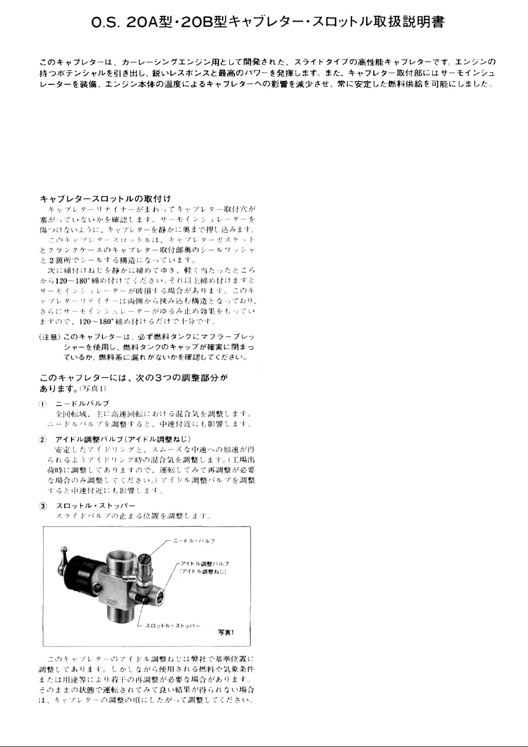
Needle Valve
Mixture Control Valve
(Mixture Control Screw)
Throttle Stop Screw
Photo1
ADJUSTING THE CARBURETTOR
Three adjustable controls are provided on this carbuettor.
• The Needle Valve:
When set to produce maximum power at full
throttle, this establishes the basic fuel/air mixture
strength, which is then maintained by the carburettor's automatic mixture control system to cover
the engine's requirements at reduced throttle settings.
• The Mixture Control Valve (Mixture Control
Screw):
For adjusting the mixture strength at part-throttle
and idling speeds, to obtain steady idling and
smooth acceleration to medium speeds. The Mixture Control Valve has been factory set for the
approximate best result. First, run the engine as
received, and re-adjust the Mixture Control Valve
only when necessary.
• The Throttle Stop Screw:
For setting the position where the carburettor
rotor is closed.
Page 2
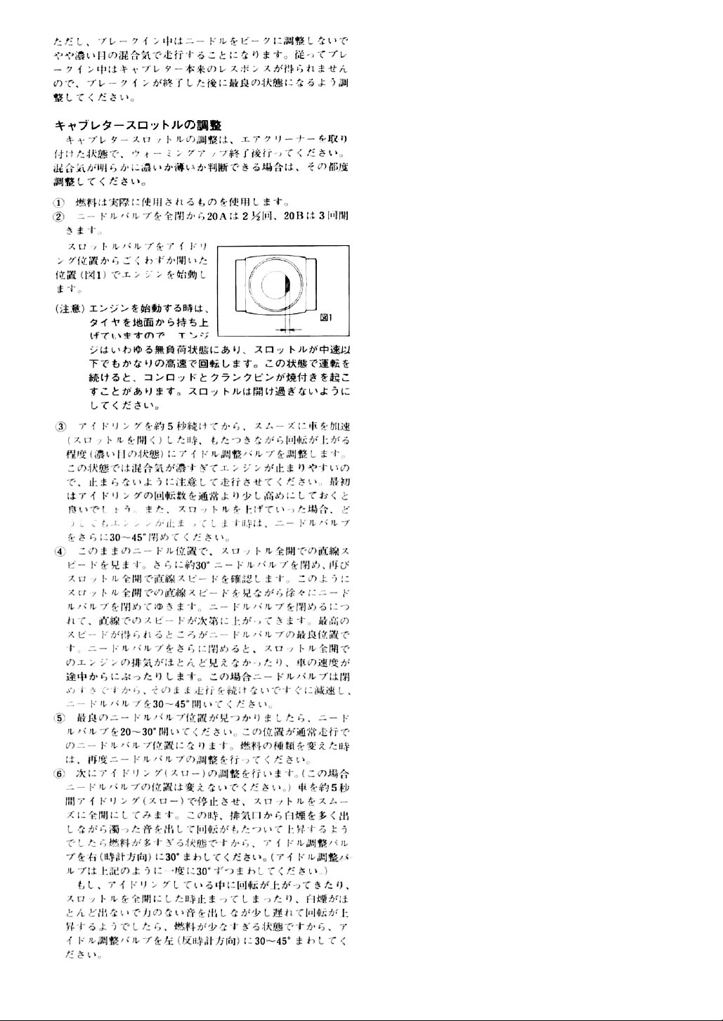
0.3-0.5mm
Fig.1
ADJUSTMENT
Note: Optimum carburettor performance is possible
only after the engine has been adequately runin - as described in the engine instruction leaflet.
Carburettor adjustment procedures should then
be carried
out
(with
the
air
cleaner
fitted,
where appropriate) as follows.
1. Use the same fuel as you intend to use for normal
running.
2. Open the Needle-Valve 2 1/2 turns (20A carburettor)
or 3 turns (20B carburettor) from the fully closed
position. Set the throttle very slightly open from
the idling position (0.3mm~0.5mm from the fully
closed position). Start the engine and allow it to
warm up.
3. Now check that the Mixture Control Valve is set
slightly rich, i.e. so that, after idling for five
seconds, the engine hesitates, when the throttle is
opened, before picking up speed. If the engine
stops due to being over-rich, set the idling speed
slightly higher by means of the Throttle Stop
Screw. Operate the car smoothly, avoiding abrupt
throttle movements at this stage. If, however, the
engine still stops through being over-rich, close
the Needle-Valve about 30° and try again.
4. Run the vehicle with this needle-valve setting (and
with throttle fully open) over the longest available
straight course, in order to observe the model's
speed. Next, return the car to the starting point,
close the Needle-Valve 30° and repeat the run,
taking note of the improvement in performance.
Continue with further runs, gradually reducing the
Needle-Valve setting and aiming to achieve the
highest straight-line speed. Remember, however,
that, if the Needle-Valve is shut down too far, the
engine will overheat and, accompanied by visibly
diminished exhaust smoke, the model will lose
speed. At this point, throttle down immediately,
stop the vehicle and reopen the Needle-Valve 30~
45°.
5. Re-check performance, making small readjustments
to the Needle-Valve, until a setting is found that
gives the highest speed without overheating, then
open the Needle-Valve 20~30° as a safety margin.
This is the optimum setting, although it may need
to be altered if a different fuel is used.
6. Having established the optimum needle-valve setting, check the Mixture Control Valve setting as
follows.
7. With the engine running, close the throttle and
allow it to idle for about five seconds, then open
the throttle fully. If, at this point, the engine puffs
out an excessive amount of smoke and the vehicle
does not accelerate smoothly and rapidly, it is
probable that the idling mixture is too rich. In this
case, turn the Mixture Control Valve clockwise
30°. If, on the other hand, the engine tends to
speed up momentarily and then cut out abruptly
when the throttle is opened, the idling mixture is
too lean. Correct this by turning the Mixture
Control Valve counter-clockwise 30~45°.
Note: Mixture Control Valve adjustment should be
made in steps of not more than 30°, carefully
checking the effect, on throttle response, of
each small adjustment.
Page 3

8. Carry out adjustments patiently, under actual running conditions, until the engine responds quickly
and positively to the throttle control.
9. With the optimum settings, light smoke is visible
during high-speed running and engine revolutions
increase smoothly during acceleration. Remember
that, if the engine is operated with the fuel/air
mixture only slightly too lean, it will overheat and
run unevenly. As with all engines, it is advisable, as
previously noted, to set both valves very slightly
on the rich side of the highest r.p.m. setting, as a
safety measure.
10. If the engine runs too fast with the throttle closed,
the Throttle Stop Screw should be turned counterclockwise a few degrees to allow the throttle opening to be reduced. Readjustment may be necessary
to suit alterations in gear ratios or the clutch
engagement point.
SUBSEQUENT READJUSTMENTS
Mixture adjustments (whether via the Mixture Control
Valve, or the Needle-Valve) cannot be made accurately under 'no load' conditions, which, in any case, are
not advised, since such operation carries the risk of
seriously damaging the engine through over-revving
and overheating.
Once the engine has been run-in (see engine instructions) and the carburettor controls properly set up,
it should be unnecessary to alter the mixture settings,
except to make minor adjustments to the NeedleValve occasionally, to take account of variations in
climatic conditions.
The use of a different fuel, however, particularly
one containing more, or less, nitromethane and/or
a different type or proportion of lubricating oil, is
likely to call for some readjustment of the NeedleValve.
Remember that, as a safety measure, it is advisable
to increase the Needle-Valve opening by an extra
half-turn counter-clockwise, prior to establishing
a new setting. The same applies if the silencer type
is changed. A different silencer may alter the exhaust
pressure applied to the fuel feed and call for a revised
Needle-Valve setting.
'Flats' for
8mm wrench
Slide Valve
•Flats' for
6mm wrench
Slide Valve Extension
CARBURETTOR CLEANLINESS
The correct functioning of the carburettor depends
on its small fuel orifices remaining clear. The minute
particles of foreign matter that are present in any
fuel, can easily partially obstruct these orifices and
upset mixture strength so that engine performance
becomes erratic and unreliable.
O.S. 'Super-Filters' (large and small) are available, as
optional extras, to deal with this problem. One of
these filters, fitted to the outlet tube inside your
refueling container, will prevent the entry of foreign
material into the fuel tank. It is also recommended
trial a good in-line filter be installed between the tank
and carburettor. Do not forget to clean the filters
regularly to remove dirt and lint that accumulate on
the filter screens. Also, clean the carburettor itself
occasionally.
Fig.2
Page 4

First rotate the Mixture Control Valve
until its slotted head is Hush with the
carburettor body
1.
0.5mm(20B)
Then screw the valve in exactly 1 turn
(20B carburettor), or 3 turns (20A
carburettor).
Mixture Control Valve
Carburettor Body
mm
(20
BALL LINK AND SLIDE VALVE EXTENSION
When readjusting the position of the Ball Link,
always apply a 6mm spanner or wrench to the flats
on the Slide Valve Extension, before attempting to
loosen or tighten the ball link retaining screw. Carefully ease back the Dust Cover bellows to allow access
to the flats. If it should become necessary (e.g. for
cleaning) to disassemble the throttle parts, first
2 turns
A)
1 turn
unscrew the Slide Valve guide screw and withdraw
the complete sub-assembly from the carburettor
body. Use the correct size (8mm) wrench when
unscrewing the Slide Valve from the Slide Valve
Extension. See Fig. 2 and parts drawing (below).
Fig.3
REALIGNMENT OF MIXTURE CONTROL VALVE
In the course of making carburettor adjustments, it
is just possible that the Mixture Control Valve may
be inadvertently screwed in or out too far and thereby moved beyond its effective adjustment range.
Its basic position can be found by first rotating the
Mixture Control Valve until its .slotted head is flush
with the carburettor body. The valve is then screwed
in exactly 1 turn (20B carburettor), or 3 turns (20A
carburettor), to establish its neutral position. See
Fig. 3 (above, left).
PARTS LIST
Description
Throttle Stop Screw (w/spring)
Mixture Control Valve Assembly
"0"Ring(L) for Mixture Control Valve
"0" Ring(S) for Mixture Control Valve
Needle Valve Assembly
"0" Ring for needle
Universal Nipple No.9(w/sealing washer)
Carburettor Body (fitted with Thermo-lnsulator)
Slide Valve Guide Screw
Carburettor Rubber Gasket
Carburettor Sealing Washer
Slide valve
Metering Needle Assembly (w/spring)
Slide Valve Extension
Dust Cover
Ball Link No.1
The specifications are subject to alteration for improvement without notice.
6-15 3-chome Imagawa Higashisurniyoshi-ku
Osaka 546, Japan. TEL (06) 702-0225
© Copyright 1995 by O.S. Engines Mfg. Co., Ltd. All rights reserved. Printed in Japan
Code
No.
20A
23818500
23818180
46066319
22781800
23818150
46066319
23818176
23818100
45581820
29015019
23818190
23818201
23818300
23818211
22884210
23818400
FAX (06)704-2722
20B
23818110
23818251
23818310
60130180 29507
 Loading...