

Orphee Mythic 22-AL User manual

REF : M22AL/UM/EN/004
MYTHIC 22 AL
Copyright© Orphee SA. All Rights Reserved.
Page 1/109
Revision Nb
Date
Author
Software
Comments
01
28/05/10
HC
> V0.4.0
Creation.
02
25/06/10
HC
> V0.5.0
Update of the entire document.
03
04/08/10
HC
> 1.0
Update of the sections 3.4.3/3.4.1/3.4.4/5.10.1/7.2
04
13/08/10
HC
> 1.0
Add the Declaration of Conformity
M
ORPHEE SA
19, chemin du champ des filles
CH-1228 Plan-les-Ouates
SWITZERLAND
Tel : +41 22 884 90 90
Fax : +41 22 884 90 99
http://www.orphee-medical.com
CONTACT ADDRESS
MANUFACTURER
REVISIONS
LOCAL AGENT
REF : M22AL/UM/EN/004
Page 2/109
Copyright© Orphee SA. All Rights Reserved.
MYTHIC 22 AL
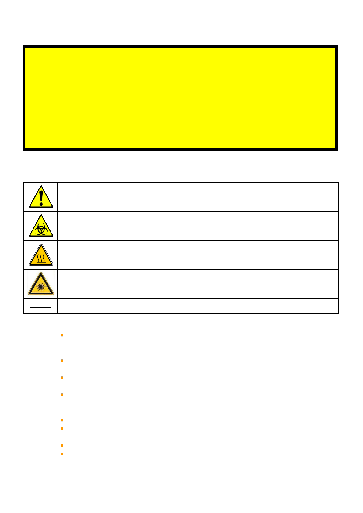
CAUTION - RISK OF DANGER
Indicates a procedure to be strictly respected in order to avoid any risks for the
operator (user) or damages on the instrument or on the quality of results.
CAUTION – BIOHAZARD RISK
Indicates that wearing gloves is mandatory before performing the described
operation due to risk of contact with materials that may be infectious.
CAUTION – HOT SURFACE
Indicates hot temperatures surfaces and risk of burns
CAUTION – CLASS 2 LASER RADIATION
Indicates laser radiation and do not stare into the beam
NOTA
Indicates important additional information
WARNING
Important Safety Instructions
Must be read before attempting to install the product.
The slots and openings in the back or bottom are provided for necessary ventilation. To
ensure reliable operation of this apparatus or its DC adaptor, and to protect it from
overheating, these openings must never be blocked or covered.
Do not place this apparatus or its DC adaptor near or over a radiator or heat resistor, or
where it is exposed to direct sunlight.
Do not place a vessel containing liquid on this apparatus and its DC adaptor, as this can result
in a risk of fire or electric shock.
Do not expose this apparatus or its DC adaptor to rain or place it near water. If this
apparatus or its DC adapter accidentally gets wet, unplug it and contact your service center
immediately.
Make sure to pull out the power cord from the outlet before cleaning.
Do not overload wall outlets, extension cords or adaptors beyond their capacity, since this
can result in fire or electric shock.
Do not use travel power adapter
Power-supply cords should be routed so that they are not likely to be walked on or pinched by
items placed upon or against them.

REF : M22AL/UM/EN/004
MYTHIC 22 AL
Copyright© Orphee SA. All Rights Reserved.
Page 3/109
To protect apparatus or its DC adaptor from a lightning storm, or when it is left unused for
long periods of time, unplug it from the wall outlet. This will prevent damage to the set due to
lightning and power line surges.
Before connecting the AC power cord to the DC adaptor outlet, make sure the voltage
designation of the DC adaptor corresponds to the local electrical supply.
Never insert anything metallic into the open parts of the DC adaptor. Doing so many create a
danger of electric shock.
To avoid electric shock, never touch the inside of the DC adaptor.
Make sure to plug the power cord in until it is firmly inserted. When removing the power
cord, make sure to hold the power plug when pulling the plug from the outlet. Do not touch
the power cord or DC adaptor with wet hands.
If this apparatus does not operate normally – in particular, if there are any unusual sounds or
smells coming from it – unplug it immediately and contact your service center.
Be sure to contact an authorized service center, when installing your set in a location with
heavy dust, high or low temperatures, high humidity or chemical substances. Failure to do so
may cause serious damage to your set.
Use only a properly grounded plug and receptacle. An improper ground may cause electric
shock or equipment damage.
To disconnect the apparatus from the mains, the plug must be pulled out from the mains
socket, therefore the mains plug shall be readily operable.
Do not install the product in an unstable location such as a shaky table or a location exposed
to vibration.
Do not drop or impart any shock to the product. If the product is damaged, disconnect the
power cord and contact your service center.
Always replace or use parts of the apparatus supplied by your service center.
The MYTHIC 22 AL is an automated hematology analyzer for in vitro diagnostic to be used in
clinical laboratories by an authorized people.
Only human blood or artificial control blood should be run.
Only the reagents mentioned in this manual are permitted to be used.
The optimum performances can be only achieved if the cleaning and maintenance
procedures are carefully followed.
All parts or surfaces of this apparatus could be potentially infective. Use adequate
protection to prevent any risk of contamination (gloves, glasses, disinfectant).
The elimination of waste supplied by this apparatus must be done in compliance with your local
authorities.

REF : M22AL/UM/EN/004
Page 4/109
Copyright© Orphee SA. All Rights Reserved.
MYTHIC 22 AL
ATTENTION
RAYONNEMENT LASER DE CLASSE 2
EN CAS D’OUVERTURE NE PAS REGARDER DANS LE FAISCEAU
CAUTION
CLASS 2 LASER RADIATION
WHEN OPEN DO NOT STARE INTO THE BEAM
This equipment has an embedded class 2 laser product.
By removing the protect cover operator could have exposure to hazardous laser
radiation.
Do not stare into the beam
All operations of service must be do after equipment is switched off.
Wavelength: 650nm
Beam divergence: 54°
Pulse duration and repetition rate: 200 scans/s
Maximum power: 1mW

REF : M22AL/UM/EN/004
MYTHIC 22 AL
Copyright© Orphee SA. All Rights Reserved.
Page 5/109
Guidance and manufacturer’s declaration – Electromagnetic emissions
The MYTHIC 22 AL is intended for use in the electromagnetic environment specified below. The customer or
the user of the MYTHIC 22 AL should assure that it is used in such an environment.
Emissions test
Compliance level
Electromagnetic environment - guidance
Harmonic emissions
IEC 61000-3-2
Class A
The MYTHIC 22 AL is suitable for use in all establishments, including
domestic establishments and those directly connected to the public
low-voltage power supply network that supplies buildings used for
domestic purposes.
Voltage fluctuations/flicker
emissions
IEC 61000-3-3
Complies
Guidance and manufacturer’s declaration – Electromagnetic immunity
The MYTHIC 22 AL is intended for use in the electromagnetic environment specified below. The customer or
the user of the MYTHIC 22 AL should assure that it is used in such an environment.
Immunity test
IEC 60601 test level
Compliance
level
Electromagnetic environment - guidance
Electrostatic
discharge (ESD)
IEC 61000-4-2
±6 kV contact
±8 kV air
Complies
Floors should be wood, concrete or ceramic tile. If floors
are covered with synthetic material, the relative
humidity should be at least 30 %.
Electrical fast
transient/burst
IEC 61000-4-4
±2 kV for power supply lines
±1 kV for input/output lines
Complies
Mains power quality should be that of a typical
commercial or hospital environment.
Surge
IEC 61000-4-5
±1 kV differential mode
±2 kV common mode
Complies
Mains power quality should be that of a typical
commercial or hospital environment.
Voltage dips, short
interruptions and
voltage variations
on power supply
input lines
IEC 61000-4-11
<5 % UT
(>95 % dip in UT) for 0,5 cycle
40 % UT
(60 % dip in UT) for 5 cycles
70 % UT
(30 % dip in UT) for 25 cycles
<5 % UT
(>95 % dip in UT) for 5 sec
Complies
Mains power quality should be that of a typical
commercial or hospital environment. If the user of the
MYTHIC 22 AL requires continued operation during
power
mains interruptions, it is recommended that the MYTHIC
22 AL be powered from an uninterruptible power
supply or a battery.
Power frequency
(50/60 Hz)
magnetic field
IEC 61000-4-8
3 A/m
Complies
Power frequency magnetic fields should be at levels
characteristic of a typical location in a typical commercial
or hospital environment.
NOTE UT is the a.c. mains voltage prior to application of the test level.
This equipment needs special precautions regarding general requirements for safety.
REF : M22AL/UM/EN/004
Page 6/109
Copyright© Orphee SA. All Rights Reserved.
MYTHIC 22 AL
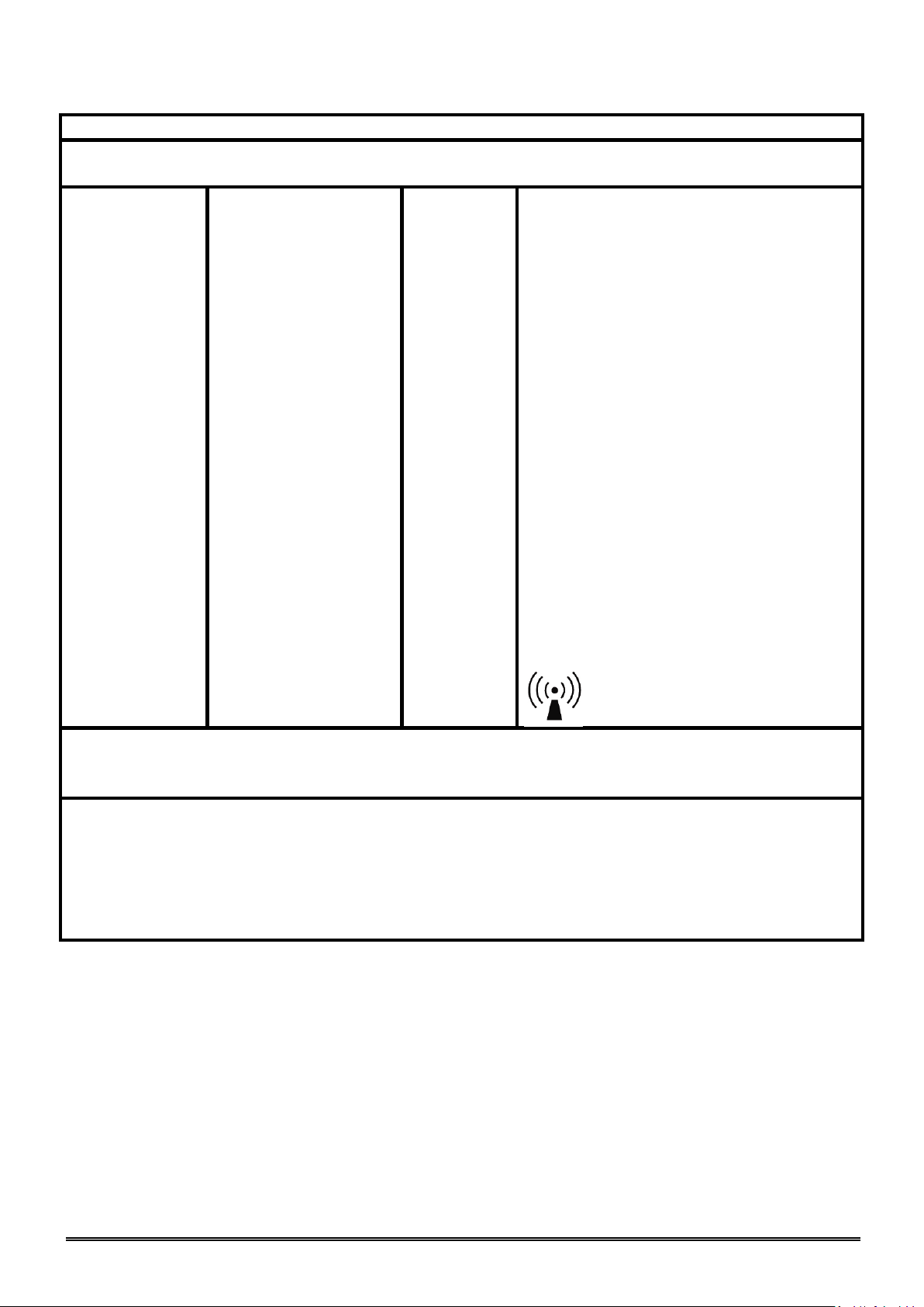
Guidance and manufacturer’s declaration – Electromagnetic immunity
The MYTHIC 22 AL is intended for use in the electromagnetic environment specified below. The customer or
the user of the MYTHIC 22 AL should assure that it is used in such an environment.
Immunity test
IEC 60601 test level
Compliance
level
Electromagnetic environment - guidance
Portable and mobile RF communications equipment should
be used no closer to any part of the MYTHIC 22 AL,
including cables, than the recommended separation
distance calculated from the equation applicable to the
frequency of the transmitter.
Recommended separation distance
Conducted RF
IEC 61000-4-6
3 Vrms
150Khz to 80Mhz
3 Vrms
d
= 1,2√P
Radiated RF
IEC 61000-4-3
3 Vrms
80Mhz to 2,5Ghz
3 Vrms
d
= 1,2√P 80MHz to 800MHz
d
= 2,3√P 800MHz to 2,5GHz
Where P is the maximum output power rating of the
transmitter in watts (W) according to the transmitter
manufacturer and d is the recommended separation
distance in meters (m).
Field strengths from fixed RF transmitters, as
determined by an electromagnetic site survey,a should be
less than the compliance level in each frequency range
Interference may occur in the vicinity of equipment
marked with the following symbol:
NOTE 1 At 80Mhz and 800MHz, the higher frequency range applies.
NOTE 2 Theses guidelines may not apply in all situations. Electromagnetic propagation is affected by absorption and reflection from
structures, objects and people.
a
Field strengths from fixed transmitters, such as base stations for radio (cellular/cordless) telephones and land mobile radios,
amateur radio, AM an FM radio broadcast and TV broadcast cannot be predicted theoretically with accuracy. To assess the
electromagnetic environment due to fixed RF transmitters, an electromagnetic site survey should considered. If the measured field
strength in the location in which the MYTHIC 22 AL is used exceeds the applicable RF compliance level above, the MYTHIC 22 AL
should be observed to verify normal operation. If abnormal performance is observed, additional measures may be necessary, such as reorienting or relocating the MYTHIC 22 AL.
b
Over the frequency range 150KHz to 80MHz, field strengths should be less than 3V/m.

REF : M22AL/UM/EN/004
MYTHIC 22 AL
Copyright© Orphee SA. All Rights Reserved.
Page 7/109
The symbol on the product indicates that this product may not be treated as household waste. Instead it shall be handed over
the applicable collection point for the recycling of electrical and electronic equipment. By ensuring this product is disposed of
correctly, you will help prevent potential negative consequences for the environment and human health, which could otherwise be
caused by inappropriate waste handling of this product. For more detailed information about recycling of this product, please contact
your local city office or your distributor of this product.
NOTE: This equipment has been tested and found to comply with the limits for a Class B digital device, pursuant to
Part 15 of the FCC Rules. These limits are designed to provide reasonable protection against harmful interference in a
residential installation. This equipment generates uses and can radiate radio frequency energy and, if not installed and
used in accordance with the instructions, may cause harmful interference to radio communications. However, there is
no guarantee that interference will not occur in a particular installation. If this equipment does cause harmful
interference to radio or television reception, which can be determined by turning the equipment off and on, the user is
encouraged to try to correct the interference by one or more of the following measures:
- Reorient or relocate the receiving antenna.
- Increase the separation between the equipment and receiver.
- Connect the equipment into an outlet on a circuit different from that to which the receiver is connected.
- Consult the dealer or an experienced radio/TV technician for help.
The user may find the following booklet, prepared by the Federal Communications Commission, helpful:
How to identify and Resolve Radio/TV Interference Problems. This booklet is available from the U.S. Government
Printing Office, Washington, D.C. 20402, Stock No. 004-000-00345-4.
Pursuant to Part 15.21 of the FCC Rules, any changes or modifications to this equipment not expressly approved by C2

REF : M22AL/UM/EN/004
Page 8/109
Copyright© Orphee SA. All Rights Reserved.
MYTHIC 22 AL
Name und Adresse der Firma
Nom et adresse de l’entreprise
Nome e indirizzo della ditta
Name and address of the firm
Orphée S.A.
19 Chemin du Champ des Filles
1228 Plan Les Ouates
Wir erklären in alleiniger Verantwortung, dass
Nous déclarons sous notre propre responsabilité que
Dichiariamo sotto nostra responsabilità che
We declare under our sole responsibility that
das Medizinprodukt für die In-vitro-Diagnostik
le dispositif médical de diagnostic in vitro
il dispositivo medico-diagnostico in vitro
the in vitro diagnostic medical device
Mythic 22 AL
Ref. M22AL
mit folgender Klassifizierung nach der Richtlinie über In-vitro-Diagnostika 98/79/EG
avec la classification selon la directive relative aux dispositifs médicaux de diagnostic in vitro 98/79/CE
con la classificazione secondo la direttiva relativa ai dispositivi medico-diagnostici in vitro 98/79/CE
classified as follows according to the directive on in vitro diagnostic medical devices 98/79/EC
Produkt der Liste A, Anhang II / Dispositif de la liste A, annexe II /
Dispositivo dell’elenco A, allegato II / Device of List A, Annex II
Produkt der Liste B, Anhang II / Dispositif de la liste B, annexe II /
Dispositivo dell’elenco B, allegato II / Device of List B, Annex II
Produkt zur Eigenanwendung, das nicht in Anhang II genannt ist /
Dispositif destiné à l’autodiagnostic non listé dans l’annexe II /
Dispositivo per test autodiagnostico non elencato nell’allegato II /
Device for self-testing not listed in Annex II
Sonstiges Produkt / Autre dispositif / Altro dispostivo / Other device
allen Anforderungen der Richtlinie über In-vitro-Diagnostika 98/79/EG entspricht, die anwendbar sind.
remplit toutes les exigences de la directive relative aux dispositifs médicaux de diagnostic in vitro 98/79/CE
qui le concernent.
soddisfa tutte le disposizioni della direttiva relativa ai dispositivi medico-diagnostici in vitro 98/79/CE che lo
riguardano.
meets all the provisions of the directive on in vitro diagnostic medical devices 98/79/EC which apply to it.
KONFORMITÄTSERKLÄRUNG /
DECLARATION DE CONFORMITE
DECLARATION OF CONFORMITY /
DICHIARAZIONE DI CONFORMITA

REF : M22AL/UM/EN/004
MYTHIC 22 AL
Copyright© Orphee SA. All Rights Reserved.
Page 9/109
Angewandte Gemeinsame Technische
Spezifikationen, harmonisierte Normen,
nationale Normen oder andere normative
Dokumente
Spécifications techniques communes,
normes harmonisées, normes nationales et
autres documents normatifs appliqués
Specifiche tecniche comuni, norme
armonizzate o nazionali applicate, altri
documenti normativi applicati
Applied common technical specifications,
harmonised standards, national standards or
other normative documents
IEC 60825-1:2007
IEC 61010-1:2001
IEC 61010-2-101:2002
IEC 61010-2-081:2001 and A1:2003
IEC 61326-2-6:2005
Konformitätsbewertungsverfahren
Procédure d’évaluation de la conformité
Procedimentodi valutazionedellaconformità
Conformity assessment procedure
Annex III
Konformitätsbewertungsstelle (falls beigezogen)
Organe respons. de l'évaluat.de la conformité(si
consulté)
Organo incaric. della valutaz. della conform. (se
consultato)
Notified Body (if consulted)
N/A
Ort, Datum / Lieu, date /
Luogo, data / Place, date
Geneva, 10.08.2010
Name und Funktion / Nom et fonction /Nome e
funzione / Name and function
Tomasz Tuora
CEO & President

REF : M22AL/UM/EN/004
Page 10/109
Copyright© Orphee SA. All Rights Reserved.
MYTHIC 22 AL

REF : M22AL/UM/EN/004
MYTHIC 22 AL
Copyright© Orphee SA. All Rights Reserved.
Page 11/109
TABLE OF CONTENTS
1. INSTALLATION ..................................................................................................... 14
1.1 UNPACKING .................................................................................................................................................................................................. 14
1.1.1 Introduction ................................................................................................................................................................................................. 14
1.1.2 Unpacking Procedure ................................................................................................................................................................................... 14
1.1.3 Visual checking ............................................................................................................................................................................................. 15
1.2 INSTALLATION CONSTRAINTS .................................................................................................................................................................. 16
1.2.1 Installation place ......................................................................................................................................................................................... 16
1.2.2 Installation environment ............................................................................................................................................................................ 16
1.3 ELECTRICAL CONNECTIONS ........................................................................................................................................................................ 16
1.3.1 Rear connectors ........................................................................................................................................................................................... 16
1.3.2 Front connectors ......................................................................................................................................................................................... 17
1.3.3 Power supply block ....................................................................................................................................................................................... 17
1.4 PRINTER CONNECTION ................................................................................................................................................................................ 17
1.5 CONNECTION, CHANGE AND PRIMING REAGENTS .................................................................................................................................... 18
1.5.1 Connection ..................................................................................................................................................................................................... 18
1.5.2 Priming ............................................................................................................................................................................................................ 19
1.6 TRANSPORTATION AND STORAGE ............................................................................................................................................................. 21
2. GENERAL OVERVIEW ............................................................................................... 22
2.1 INTENDED USE ........................................................................................................................................................................................... 22
2.2 GENERALITIES ............................................................................................................................................................................................ 22
2.3 OVERVIEW ................................................................................................................................................................................................... 23
2.4 MAIN PART DESCRIPTION .......................................................................................................................................................................... 23
2.4.1 Display ............................................................................................................................................................................................................ 23
2.4.2 Dilution fluidic part ..................................................................................................................................................................................... 25
2.4.3 Power Supply Block ...................................................................................................................................................................................... 26
2.4.4 Reagent tray ................................................................................................................................................................................................. 27
2.4.5 Sampler .......................................................................................................................................................................................................... 27
3. INSTRUMENT SET UP .............................................................................................. 28
3.1 USER’S IDENTIFICATION.......................................................................................................................................................................... 28
3.1.1 Start Up Machine ........................................................................................................................................................................................ 28
3.1.2 In process ..................................................................................................................................................................................................... 28
3.2 SYSTEM STATUS......................................................................................................................................................................................... 29
3.3 SET UP ......................................................................................................................................................................................................... 29
3.4 ADVANCED SET-UP ..................................................................................................................................................................................... 30
3.4.1 Sampler option: ............................................................................................................................................................................................ 30
3.4.1 Analysis options: .......................................................................................................................................................................................... 30
3.4.2 Lab. parameters: .......................................................................................................................................................................................... 31
3.4.3 Other Setting: ............................................................................................................................................................................................. 34
3.4.1 Printer set up: .............................................................................................................................................................................................. 34
3.4.1 Communication: ............................................................................................................................................................................................. 35
3.4.2 Calibration factor: ....................................................................................................................................................................................... 36
3.4.3 Storage options: ........................................................................................................................................................................................... 36
3.4.4 Version release:............................................................................................................................................................................................ 37
4. SPECIFICATIONS ................................................................................................... 38
4.1 ANALYTICAL SPECIFICATIONS ................................................................................................................................................................. 38
4.2 PHYSICAL SPECIFICATIONS ...................................................................................................................................................................... 40
4.3 REAGENTS SPECIFICATIONS .................................................................................................................................................................... 42
4.3.1 Diluent ............................................................................................................................................................................................................ 42
4.3.2 Lytic reagent “OnlyOne” ............................................................................................................................................................................ 43
4.3.3 Cleaning solution ........................................................................................................................................................................................... 44
4.4 ANALYTICAL LIMITATIONS ...................................................................................................................................................................... 45
4.4.1 Recommendations ......................................................................................................................................................................................... 45
4.4.2 Interferences............................................................................................................................................................................................... 45

REF : M22AL/UM/EN/004
Page 12/109
Copyright© Orphee SA. All Rights Reserved.
MYTHIC 22 AL
5. SAMPLE ANALYSIS ................................................................................................. 50
5.1 VERIFICATIONS BEFORE STARTING ......................................................................................................................................................... 50
5.2 SWITCH ON ................................................................................................................................................................................................ 50
5.3 REAGENT REPLACEMENT ............................................................................................................................................................................. 50
5.4 START UP RINSING...................................................................................................................................................................................... 51
5.5 PREPARATIONS BEFORE ANALYSIS ........................................................................................................................................................... 52
5.5.1 Blood collection ............................................................................................................................................................................................ 52
5.5.2 Blood sample collection tube ..................................................................................................................................................................... 52
5.6 ANALYSIS ................................................................................................................................................................................................... 53
5.6.1 Introduction ................................................................................................................................................................................................. 53
5.6.2 Working rules ............................................................................................................................................................................................... 53
5.6.3 Work list ........................................................................................................................................................................................................ 54
5.6.4 Modify an order ........................................................................................................................................................................................... 55
5.6.5 New Order .................................................................................................................................................................................................... 55
5.6.6 Display run ..................................................................................................................................................................................................... 55
5.6.7 Run Rack......................................................................................................................................................................................................... 56
5.6.8 STAT or other vial Sample Identification ............................................................................................................................................. 59
5.6.9 STAT or other vial sample run .................................................................................................................................................................. 60
5.7 DISPLAY RUNS ............................................................................................................................................................................................. 61
5.8 PRINTING .................................................................................................................................................................................................... 63
5.8.1 PCL3/LX 300 (USB) model report ............................................................................................................................................................ 63
5.8.1 PCL6 model report ....................................................................................................................................................................................... 64
5.9 LOGS INTERVENTIONS .............................................................................................................................................................................. 65
5.10 ARCHIVE ...................................................................................................................................................................................................... 66
5.10.1 Results ........................................................................................................................................................................................................... 66
5.10.2 View ................................................................................................................................................................................................................ 67
5.11 STAND BY AND SHUT DOWN ...................................................................................................................................................................... 68
6. QUALITY CONTROL ................................................................................................ 69
6.1 INTRODUCTION .......................................................................................................................................................................................... 69
6.2 QUALITY CONTROL .................................................................................................................................................................................... 69
6.2.1 Change ............................................................................................................................................................................................................ 70
6.2.2 Run control blood ......................................................................................................................................................................................... 71
6.3 REPEATABILITY .......................................................................................................................................................................................... 72
7. CALIBRATION ....................................................................................................... 73
7.1 RUN CALIBRATOR ........................................................................................................................................................................................ 74
7.1.1 Calibration blood analysis ........................................................................................................................................................................... 74
7.1.2 Calibration ..................................................................................................................................................................................................... 74
7.2 TARGET VALUES MODIFICATIONS ............................................................................................................................................................ 75
8. TECHNOLOGY ....................................................................................................... 76
8.1 DETECTION PRINCIPLE ............................................................................................................................................................................... 76
8.1.1 WBC, RBC, PLT Counting............................................................................................................................................................................. 76
8.1.2 Five part diff measurement ...................................................................................................................................................................... 77
8.1.3 Hemoglobin measurement .......................................................................................................................................................................... 78
8.2 LEUKOCYTE ANALYSIS ............................................................................................................................................................................... 78
8.2.1 Measurement ................................................................................................................................................................................................ 78
8.2.2 Local blood control limitations .................................................................................................................................................................. 79
8.3 ERYTHROCYTE ANALYSIS ........................................................................................................................................................................... 80
8.4 ANALYSIS OF PLATELETS ........................................................................................................................................................................... 81
8.5 FLAGS ........................................................................................................................................................................................................... 81
8.5.1 General Flags ................................................................................................................................................................................................ 81
8.5.2 Instrument Flags ......................................................................................................................................................................................... 82
8.5.3 Leukocytes Flags .......................................................................................................................................................................................... 82
8.5.4 Erythrocyte and HGB Flags ....................................................................................................................................................................... 83
8.5.5 Platelet Flags ................................................................................................................................................................................................ 83
8.5.6 QC Flags ........................................................................................................................................................................................................ 83
8.5.7 STARTUP Flags ............................................................................................................................................................................................ 83
8.6 HYDRAULIC & MECHANIC DESCRIPTION .................................................................................................................................................. 84
8.6.1 Auto loader module ...................................................................................................................................................................................... 84
8.6.2 Sampling module ........................................................................................................................................................................................... 84
8.6.3 Counting bath module .................................................................................................................................................................................. 84
8.6.4 Syringes module ........................................................................................................................................................................................... 84
8.6.5 Optical manifold ........................................................................................................................................................................................... 84

REF : M22AL/UM/EN/004
MYTHIC 22 AL
Copyright© Orphee SA. All Rights Reserved.
Page 13/109
8.6.6 Optical bench ................................................................................................................................................................................................ 85
8.7 SOFTWARE .................................................................................................................................................................................................. 85
8.7.1 Common Functionalities .............................................................................................................................................................................. 85
8.7.2 Menu tree ...................................................................................................................................................................................................... 86
9. SERVICE ............................................................................................................. 87
9.1 MAINTENANCE ........................................................................................................................................................................................... 87
9.1.1 Maintenance table ....................................................................................................................................................................................... 87
9.1.2 Concentrate cleaning ................................................................................................................................................................................... 88
9.1.3 Piston greasing ............................................................................................................................................................................................. 90
9.1.4 In line filter cleaning .................................................................................................................................................................................. 91
9.1.5 Barcode cleaning .......................................................................................................................................................................................... 91
9.2 CLEANING CYCLES ....................................................................................................................................................................................... 92
9.3 TROUBLESHOOTING SCREEN ..................................................................................................................................................................... 92
9.3.1 Sampler .......................................................................................................................................................................................................... 93
9.3.2 Check sensors ............................................................................................................................................................................................... 93
9.3.3 Check valves .................................................................................................................................................................................................. 93
9.3.4 Check motors fluidics ................................................................................................................................................................................. 94
9.3.5 Log errors ...................................................................................................................................................................................................... 94
9.4 REPAIRING .................................................................................................................................................................................................. 94
9.4.1 Emergency stop ............................................................................................................................................................................................ 94
9.4.2 Needle or o-ring replacement ................................................................................................................................................................... 95
9.4.3 Baths dismantling ......................................................................................................................................................................................... 98
9.4.4 Baths o-ring replacement ......................................................................................................................................................................... 100
9.4.5 Aperture block replacement..................................................................................................................................................................... 101
9.5 TROUBLESHOOTING OCCURENCES ........................................................................................................................................................... 102
9.5.1 Analytical problems ................................................................................................................................................................................... 102
9.5.2 Other problems .......................................................................................................................................................................................... 103
9.6 TROUBLESHOOTING MESSAGE ................................................................................................................................................................. 105
9.7 HYDRAULIC DIAGRAM ................................................................................................................................................................................ 108
1. INSTALLATION
REF : M22AL/UM/EN/004
Page 14/109
Copyright© Orphee SA. All Rights Reserved.
MYTHIC 22 AL
If the MYTHIC 22 AL has been stored at a temperature lower than 10°C it must be left at room
temperature during 24 hours before power on.
INSTALLATION KIT
QTY
Designation
1
Tubing 23 - DILUENT
1
Tubing 24 - WASTE
1
150W DC adaptor
1
European Power line cord
1
MYTHIC 22 AL User’s manual
1
Screwdriver Slot 1/4"
10
Racks
MAINTENANCE KIT
QTY
Designation
1
Tubing 50
10
Silicon Sleeve
5
Tie wraps
2
Rinsing Head O-ring
1
Silicon grease (3gr)
1
Short Arm TORX T10 Tool
1
Short Arm TORX T20 Tool
1. INSTALLATION
1.1 UNPACKING
1.1.1 Introduction
The MYTHIC 22 AL is an automated hematology analyzer for in vitro diagnostic use in clinical laboratories by an
authorized and trained people.
- Only human blood or artificial blood (recommended control or calibrator) should be run.
- Only the reagents mentioned in this manual are permitted to be used.
- The optimum performances can only be achieved if the cleaning and maintenance procedures are carefully
followed (see section 9.1).
1.1.2 Unpacking Procedure
Before unpacking the instrument, we recommend to check the box of the instrument and notify any damage to the
carrier.
- Open the box on the top, remove the starter kit.
- Remove the MYTHIC 22 AL from the box.
Starter kit contents:
REF : M22AL/UM/EN/004
1. INSTALLATION
MYTHIC 22 AL
Copyright© Orphee SA. All Rights Reserved.
Page 15/109
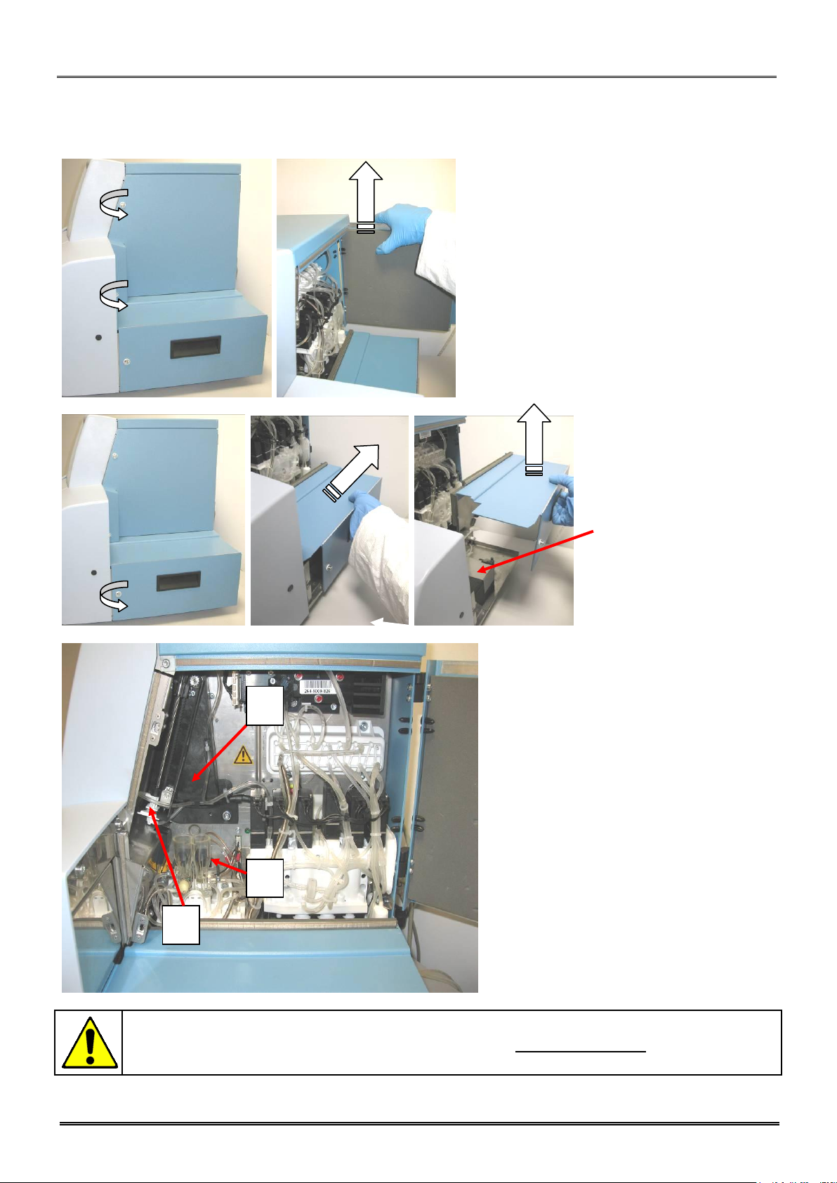
- Open the door on the right side by unscrewing
the two quarter turn screws with the key
provided in the kit.
- Open completely the door, then lift it to
remove.
- Unscrew the two quarter
turn screws with the key
provided in the kit.
- To remove the unloading
table, push to the back first
then lift it.
- Check the good fixation of
the air pump.
Remove the plastic wedge of the bath block.
To be checked:
1- Counting chambers perfectly locked in
their manifold locations.
2- Needle’s dismountable system located
in the rocker.
3- Rocker in front position at the
maximum course.
HAZARDOUS MOVING PARTS, BEWARE TO STAY AWAY FROM THESE PARTS WHEN THE
MACHINE IS SWITCHED ON. THE BARCODE READER IS A LASER CLASS II; NEVER
DISMANTLE THE COVER, IN CASE OF PROBLEM CALL ORPHEE REPRESENTATIVE.
1
2
3
1.1.3 Visual checking
1. INSTALLATION
REF : M22AL/UM/EN/004
Page 16/109
Copyright© Orphee SA. All Rights Reserved.
MYTHIC 22 AL
NOTA
Please contact Orphee’s representative if you want to use the instrument in special conditions (altitude higher
than 2000 m or special power supply conditions).
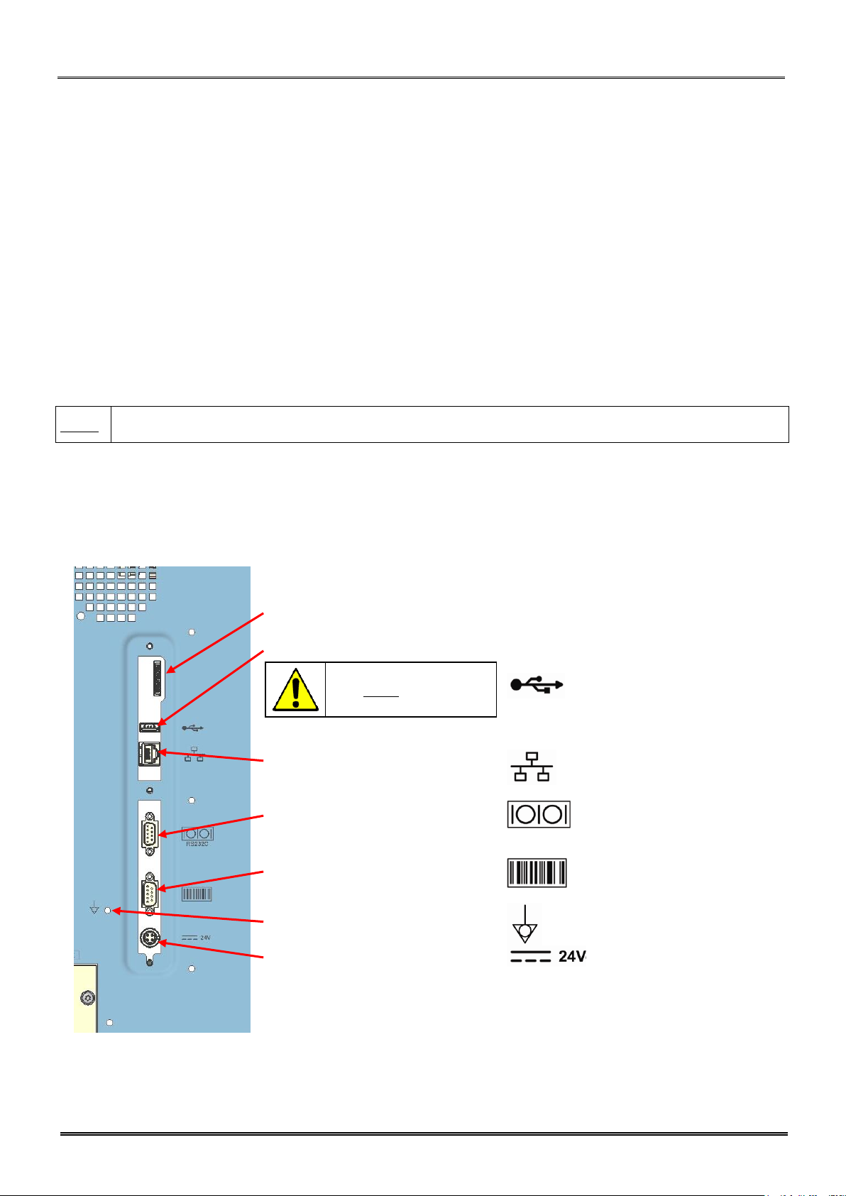
CONNECTION :
SYMBOL :
- Not available
- 1 USB port:
- Ethernet connection (TCP/IP):
- Host connection (RS232C):
- External barcode reader (RS232C):
- Equipotentiality:
- Power supply cord connection:
This USB port can be
used ONLY for the
printer connection.
1.2 INSTALLATION CONSTRAINTS
1.2.1 Installation place
To ensure that the MYTHIC 22 AL fulfills its function, place the instrument on a table which supports the weight of the
instrument, printer and reagents (~40 Kg). Leave a space of 10 cm at the rear of the instrument to ensure a wellventilated place. Avoid a place that can be exposed to direct sunlight.
1.2.2 Installation environment
a) Indoor use;
b) Altitude up to 3 000 m (see NOTA hereafter);
c) Temperature 18 °C to 34 °C;
d) Maximum relative humidity 80 % for temperatures up to 31 °C decreasing linearly to 50 % relative humidity at 40 °C;
e) MAIN supply voltage fluctuations up to ±10 % of the nominal voltage;
f) Transient over voltages typically present on the MAIN supply.
g) Rated pollution degree II.
1.3 ELECTRICAL CONNECTIONS
1.3.1 Rear connectors
REF : M22AL/UM/EN/004
1. INSTALLATION
MYTHIC 22 AL
Copyright© Orphee SA. All Rights Reserved.
Page 17/109
3 USB ports
Any output or input connections (except the printer and the barcode reader supplied by ORPHEE)
cannot be done without the ORPHEE’s representative authorization.
In case of replacement of the main power wire, supplied with the MYTHIC 22 AL, the new one must
comply with the local regulation (31.5mm cable and 250V 10A plug).
The MYTHIC 22 AL has been certified with the power supply provided with the instrument. If another
power supply is used with the instrument, Orphee or its representative will not apply any warranty on
this power supply and on the instrument. Please contact Orphee or its local representative before using
such material.
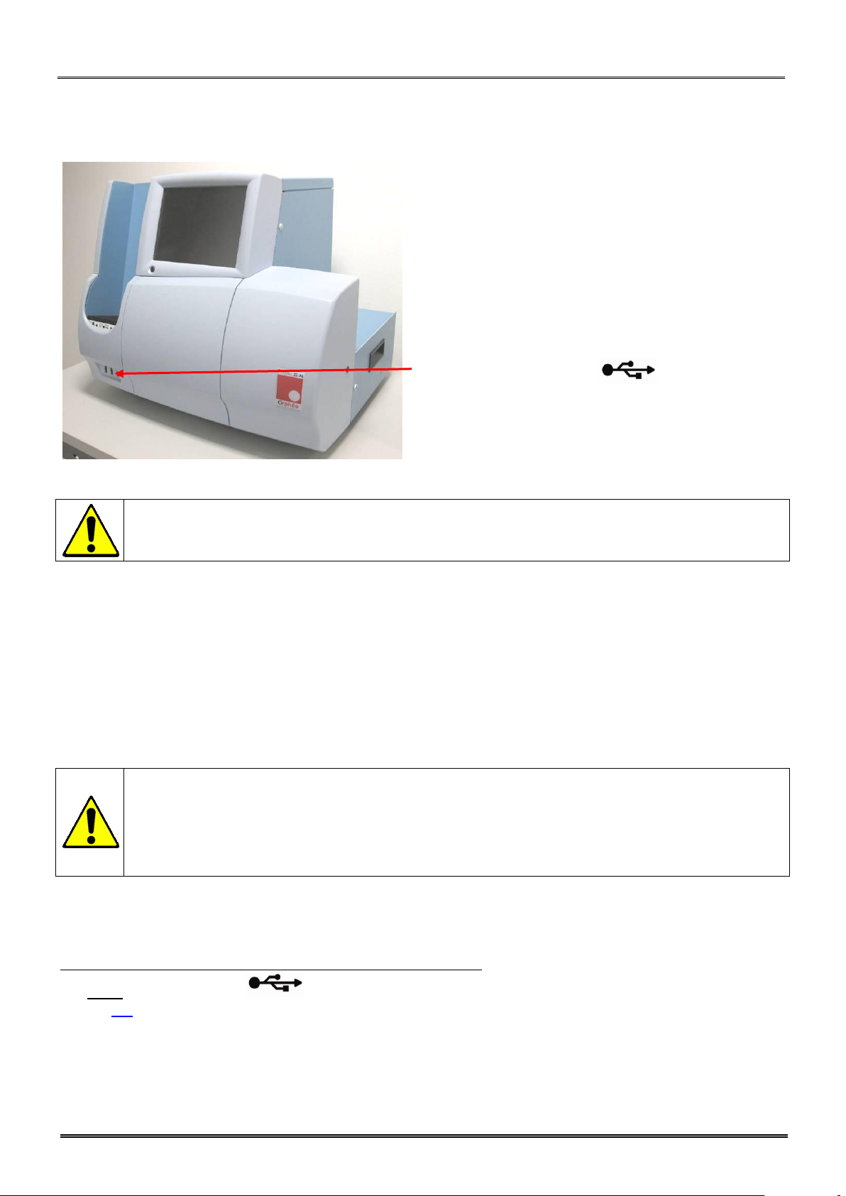
1.3.2 Front connectors
1.3.3 Power supply block
MYTHIC 22 AL must be connected to the power with the power supply block provided with the starter kit. Choose a
well-ventilated place for the block and be sure to connect this power supply in a socket-outlet with a correct earth
connection.
The power supply block must be placed at the rear of the MYTHIC 22 AL and, if possible, in an upper position to avoid
the contact with any liquid.
To disconnect electrically the MYTHIC 22 AL, remove the power supply plug from the main circuit.
1.4 PRINTER CONNECTION
Connect the printer cable in conformity with the printer user’s manual.
Use ONLY the rear USB plug ( ) of the MYTHIC 22 AL to connect the printer cable. Select the printer driver
(section 3.3).
1. INSTALLATION
REF : M22AL/UM/EN/004
Page 18/109
Copyright© Orphee SA. All Rights Reserved.
MYTHIC 22 AL
MYTHIC 22 AL works exclusively with the reagents described in section 4.3. Orphee or its local
representative will not be responsible for the quality of the results and for the maintenance of the
instrument if other commercial reagents are used.
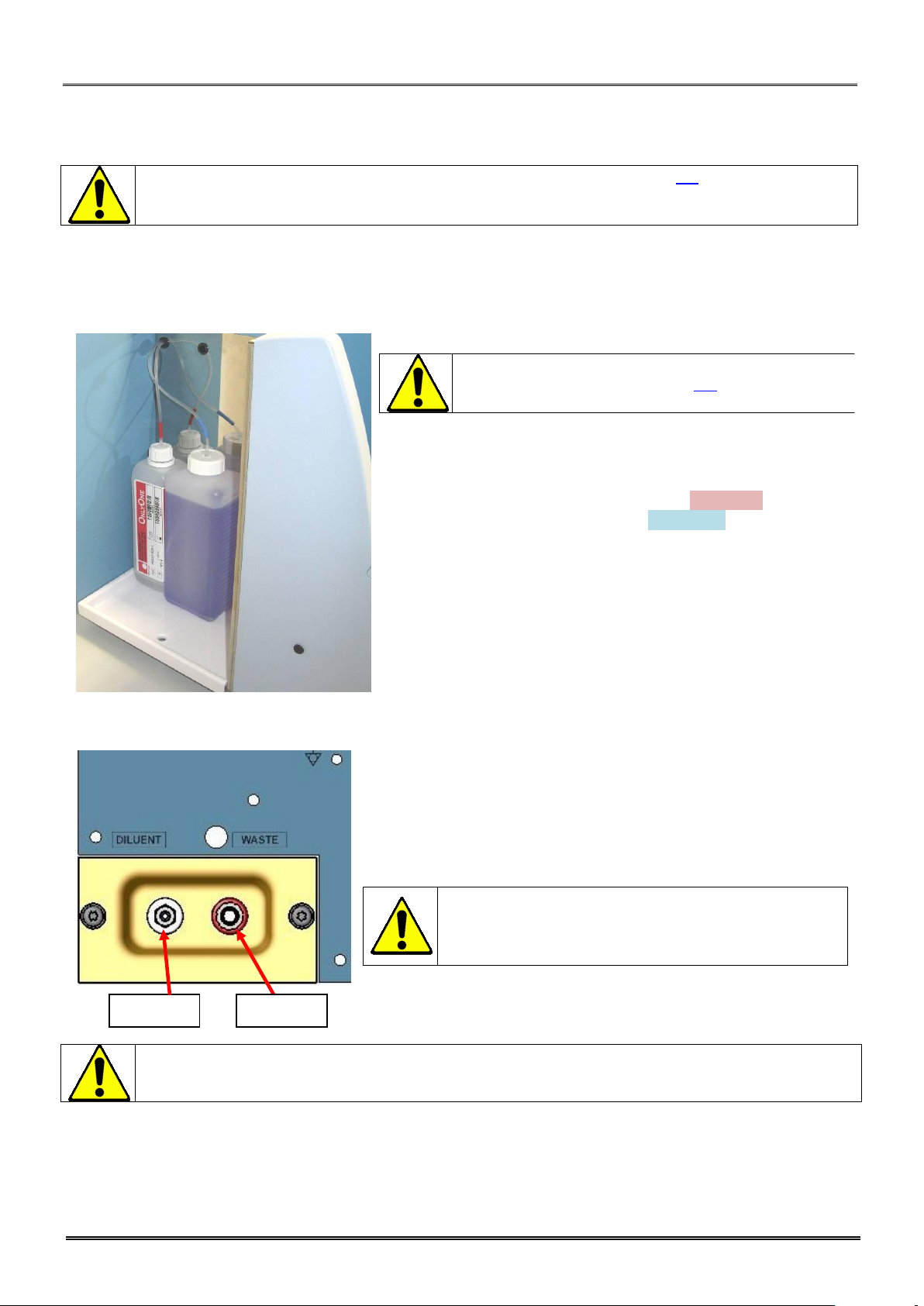
Before handling the reagents, read carefully their
specifications described in section 4.3 and check if their
shelf life dates are not reached.
- Remove the door on the left side of the instrument.
- Put the reagent bottles into the dedicated location.
- Remove the caps of the bottles.
- Tighten the red caps on the OnlyOne bottle (red sticker) and the
blue one on the cleaning solution bottle (blue sticker).
- Connect the diluent tube (male connector) on the outlet on the bottom
and tighten the cap on the diluent container.
- To use 20 liters diluent container, add the tubing straw adaptor
supplied with the installation kit.
- Connect the waste tube (female connector) on the outlet on the top and
tighten the cap on an empty container.
Do not modify the type and the length of the diluent
and waste tubes.
The diluent must be placed at the same level as the
MYTHIC 22 AL.
It is mandatory to collect the waste in a container and to treat it in compliance with your local
regulations.
Diluent
Waste
1.5 CONNECTION, CHANGE AND PRIMING REAGENTS
1.5.1 Connection
Lytic reagent and cleaning solution:
Diluent and waste:
REF : M22AL/UM/EN/004
1. INSTALLATION
MYTHIC 22 AL
Copyright© Orphee SA. All Rights Reserved.
Page 19/109
Before starting, be sure that all the reagent and waste tubes are properly connected.
The reagents must be stored 24 hours minimum at room temperature before use.
1.5.2 Priming
When using the MYTHIC 22 AL for the first time, it is necessary to perform a complete prime of the fluidic circuit.
This operation should be done by a Field Service Engineer.
Priming procedure:
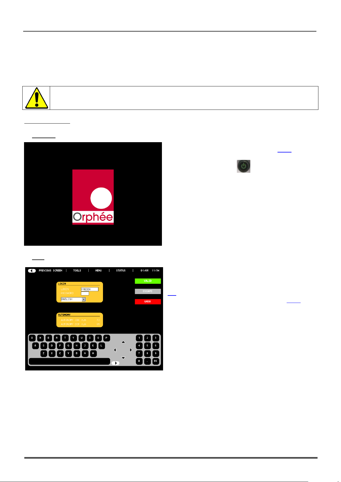
Switch on:
- Connect the power supply block (see section 2.3.4).
- Press the ON/OFF button.
- The logo Orphee appears during a few seconds.
Login:
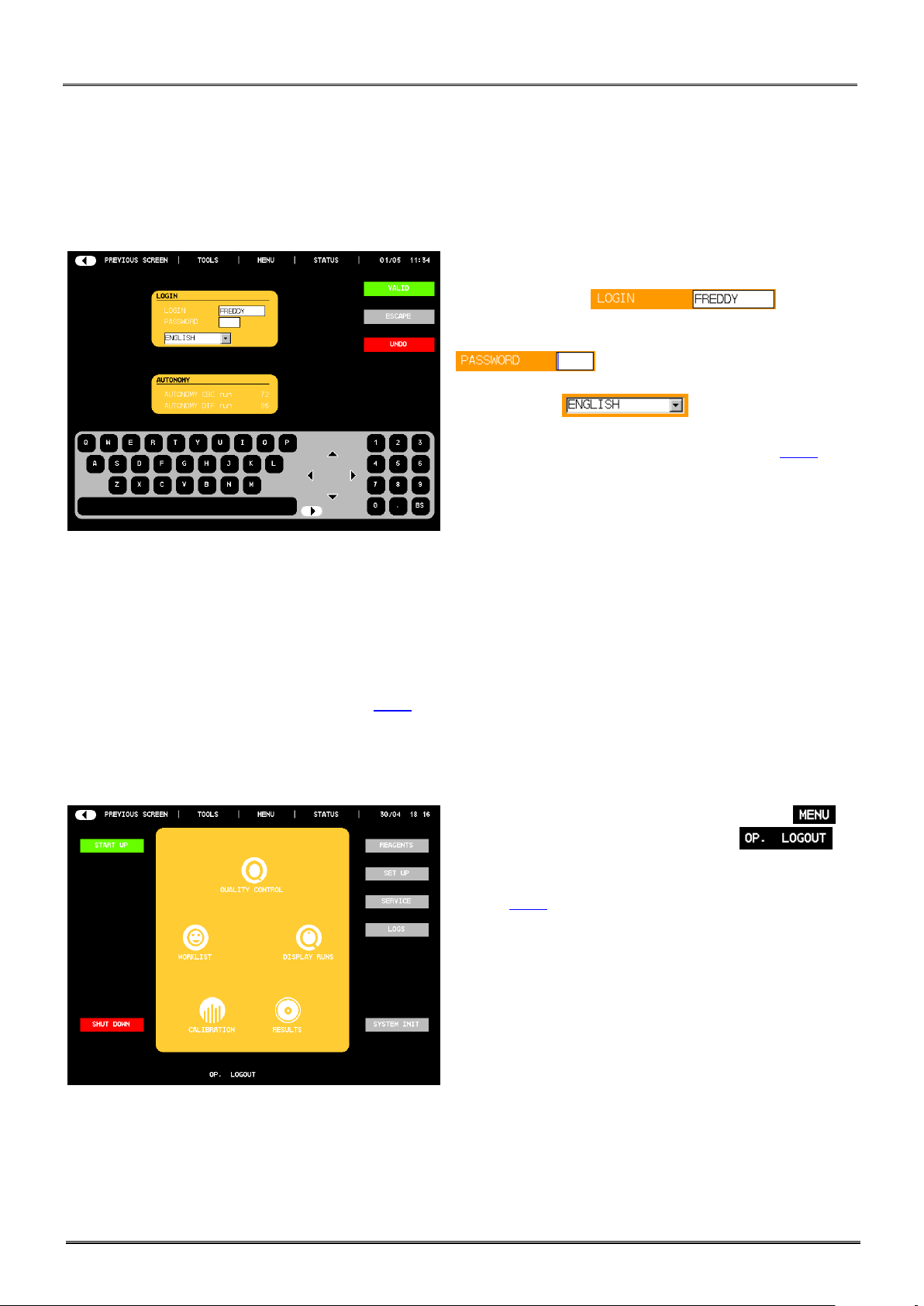
- The operator’s identification display appears.
- Enter the user’s identification, the password (see section
3.1).
- To validate or not the modification, see section 8.7.1.
- AUTONOMY (run) indicates the number of samples (runs)
you can perform (calculated with the smaller volume of
reagents).
1. INSTALLATION
REF : M22AL/UM/EN/004
Page 20/109
Copyright© Orphee SA. All Rights Reserved.
MYTHIC 22 AL
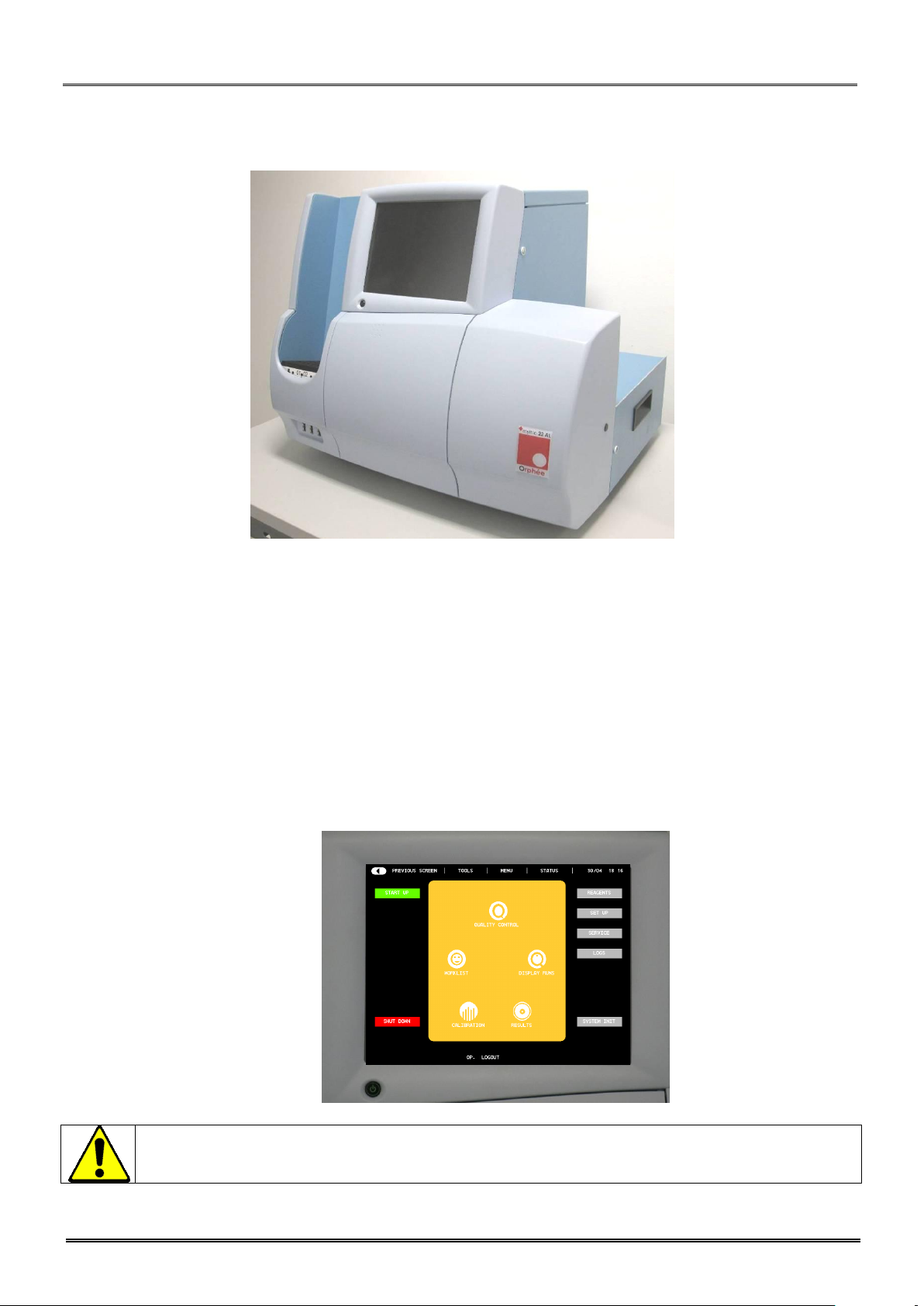
NOTA
To do an emergency stop in case of problem
push briefly on the on/off button
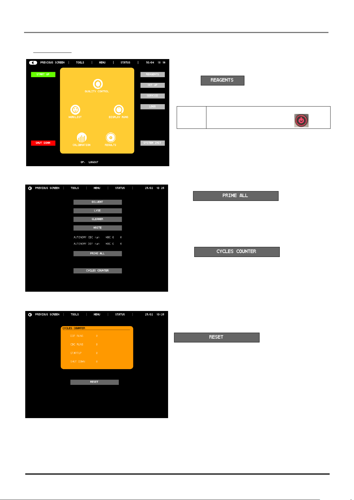
System priming:
- The main menu is displayed.
- Press on .
- Press : The MYTHIC 22
AL performs a complete priming cycle.
- AUTONOMY (run) indicates the number of samples (runs).
- To prime or to know the quantity of reagent, press the
dedicated button.
- Press to display the
cycle counters.
- To reset the counter with the button
, please contact your
Orphee’s representative.
REF : M22AL/UM/EN/004
1. INSTALLATION
MYTHIC 22 AL
Copyright© Orphee SA. All Rights Reserved.
Page 21/109
MYTHIC 22 AL IS NOW READY TO OPERATE.
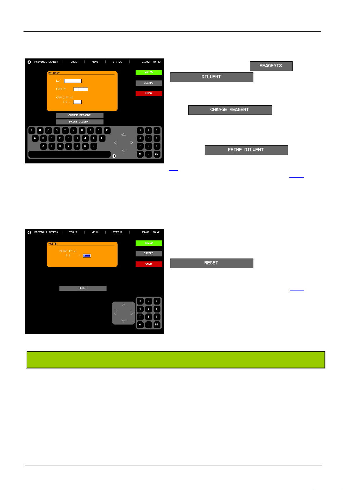
DILUENT PRIME:
LYSE AND CLEANER PRIME:
Proceed as described above for the diluent.
WASTE:
- From the MAIN MENU, press then
to have access to this
screen.
- Enter lot number, the expiry date and the container
capacity.
- Press to validate the new
entry or after changing a new container with the same
information.
- If needed, enter the container volume in milliliter.
- After the replacement of a new container or to prime the
diluent, press
- A new entry is automatically done in the logs (see section
5.9)
- To validate or not the modification, see section 8.7.1.
- Only enter the capacity of the container.
- After replacement of the waste container, press
to initialize the waste
calculation.
- To validate or not the modification, see section 8.7.1.
1.6 TRANSPORTATION AND STORAGE
Before transportation outside the laboratory, perform a complete cleaning with a disinfectant in compliance with the
local regulations.
Storage temperature: -10°C to +50°C.
If the MYTHIC 22 AL has been stored at a temperature lower than 10°C, it must be left at room temperature during 24
hours.

2. GENERAL OVERVIEW
REF : M22AL/UM/EN/004
Page 22/109
Copyright© Orphee SA. All Rights Reserved.
MYTHIC 22 AL
2. GENERAL OVERVIEW
2.1 INTENDED USE
The MYTHIC 22 AL is an automated hematology analyzer for in vitro diagnostic use in clinical laboratories by an
authorized and trained people.
- Only human blood or artificial blood (recommended control or calibrator) should be run.
- Only the reagents mentioned in this manual are permitted to be used.
- The optimum performances can be only achieved if the cleaning and maintenance procedures are carefully
followed (see section 9.1).
2.2 GENERALITIES
MYTHIC 22 AL is a fully automated analyzer performing hematological analysis on whole blood collected on EDTA K2 or
K3 tubes.
- Sampling volume: 18,2 µl (inside the needle, the total volume could be upper according to the blood remaining outside
of the needle).
- Two sampling modes: - closed tube in 10 racks of 5 tubes
- opened other vial in a special position (front door open)
- Throughput: close tube mode: > 40 samples/hour
Other vial mode: > 45 samples/hour
- 22 analysis parameters in DIF mode and 12 parameters in CBC mode:
Leukocyte parameters:
WBC White Blood Cells
LYM Lymphocytes in % & # (DIF mode only)
MON Monocytes in % & # (DIF mode only)
NEU Neutrophils in % & # (DIF mode only)
EOS Eosinophils in % & # (DIF mode only)
BAS Basophils in % & # (DIF mode only)
Erythrocyte parameters
RBC Red Blood Cells
HGB Hemoglobin
HCT Hematocrit
MCV Mean Corpuscular Volume
MCH Mean Corpuscular Hemoglobin
MCHC Mean Corpuscular Hemoglobin Concentration
RDW Red Blood cells Distribution Width
Thrombocyte parameters
PLT Platelet
MPV Mean Platelet Volume
PDW* Platelet Distribution Width
PCT* Thrombocrit
* For Investigation Use only in the United States of America
REF : M22AL/UM/EN/004
2. GENERAL OVERVIEW
MYTHIC 22 AL
Copyright© Orphee SA. All Rights Reserved.
Page 23/109
Use only a soft paper to clean the screen, never use direct liquid otherwise the screen could be
damaged.
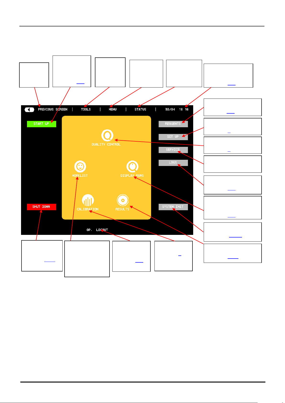
2.3 OVERVIEW
2.4 MAIN PART DESCRIPTION
2.4.1 Display
MYTHIC 22 AL consists of 9 main parts:
1. Auto loader system
2. Display.
3. Dilution hydraulic part.
4. Mono electronic board.
5. Reagent tray.
6. Connection.
7. External power supply block.
8. Printer.
9. Barcode reader (option).
2. GENERAL OVERVIEW
REF : M22AL/UM/EN/004
Page 24/109
Copyright© Orphee SA. All Rights Reserved.
MYTHIC 22 AL
Back to
previous
screen
Print,
Send,
Select
Options
Direct
access to
main menu
Start Up
rinsing and
blank control
(Section 5.2)
Cleaning and
standby mode
(section 5.11)
Patient Archive
(Section 5.10)
Quality Control
(Section 6).
Calibration
(Section 7).
Mythic Parameters
(Section 3).
Maintenance and
Service Menu
Work list
management and
Analysis
performing
(section 5.5).
Mythic Events Logs
(Section 5.9).
Reagent replacement
(section 5.3).
Log In and
Log Out
(section 3.1)
Date and Time.
System status
(Section 3.2).
Full screen run
displayed
(Section 3.1).
Display of
the sampler
status
System init
(Section 9.4.1)
Main Menu description
REF : M22AL/UM/EN/004
2. GENERAL OVERVIEW
MYTHIC 22 AL
Copyright© Orphee SA. All Rights Reserved.
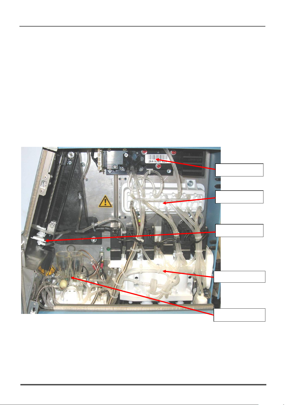
Page 25/109
Sampling module
Syringe module
Counting module
Optical manifold
Optical bench
2.4.2 Dilution fluidic part
All the fluidic part is on the right side of the instrument and consists of five modules only:
- Sampling module :
o Rocker (patented) : Manages the rise and descent of the needle.
- Syringe module (patented) consists of one block :
o Reagent syringes (Diluent, lysis), sampling and air syringes.
o Liquid valve manifold assembly and tubing.
- Counting chambers :
o WBC and RBC counting chambers and hemoglobin measurement.
o Liquid valve manifold assembly and tubing.
- Optical Manifold :
o Liquid valve manifold assembly and tubing.
- Optical bench :
o Optical bench (patented) with its flow cell (patented).
2. GENERAL OVERVIEW
REF : M22AL/UM/EN/004
Page 26/109
Copyright© Orphee SA. All Rights Reserved.
MYTHIC 22 AL
To avoid all deterioration risks, only the field service engineer may touch this electronic
board.
- In case of replacement of the main power wire supplied with the MYTHIC 22 AL, the new one must
be in compliance with the local regulations.
- The MYTHIC 22 AL has been certified with the power supply box provided with the machine. - If
another power supply is used with the instrument, Orphee or its representative will not apply any
warranty on this power supply and on the instrument. Please contact Orphee or its local representative
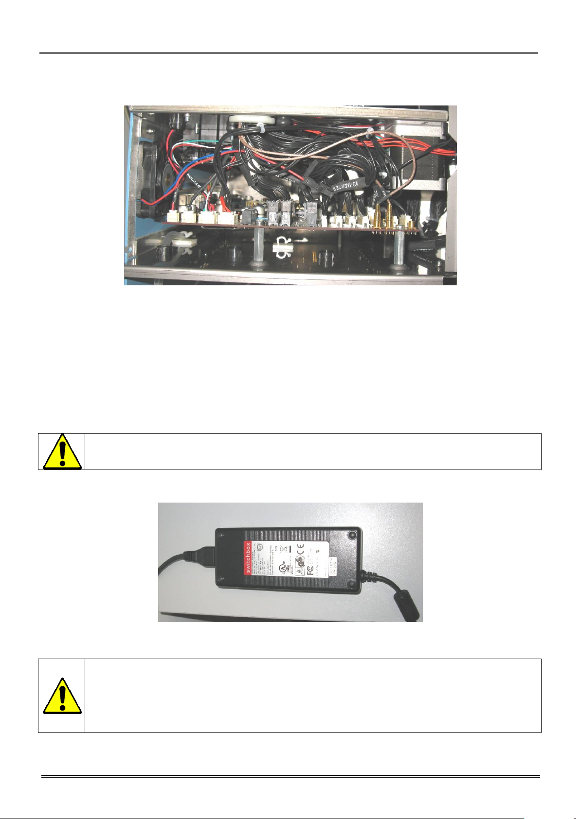
before using such material.
Mono electronic board
The mono electronic board is located between the hydraulic part and the reagent tray.
The board, driven by a 32-bit processor, manages the following parts:
- Fluidics: sample needle, rocker, syringe block motors.
- Autoloader: loading, transfer, mixing and unloading.
- Display and keyboard.
- Connection mode (RS232, Ethernet …).
- Printer.
- Measurement (Optical and resistive counting, hemoglobin measurement).
- Data processing.
- External barcode reader.
2.4.3 Power Supply Block
MYTHIC 22 AL is supplied with an external power supply block.
REF : M22AL/UM/EN/004
2. GENERAL OVERVIEW
MYTHIC 22 AL
Copyright© Orphee SA. All Rights Reserved.
Page 27/109
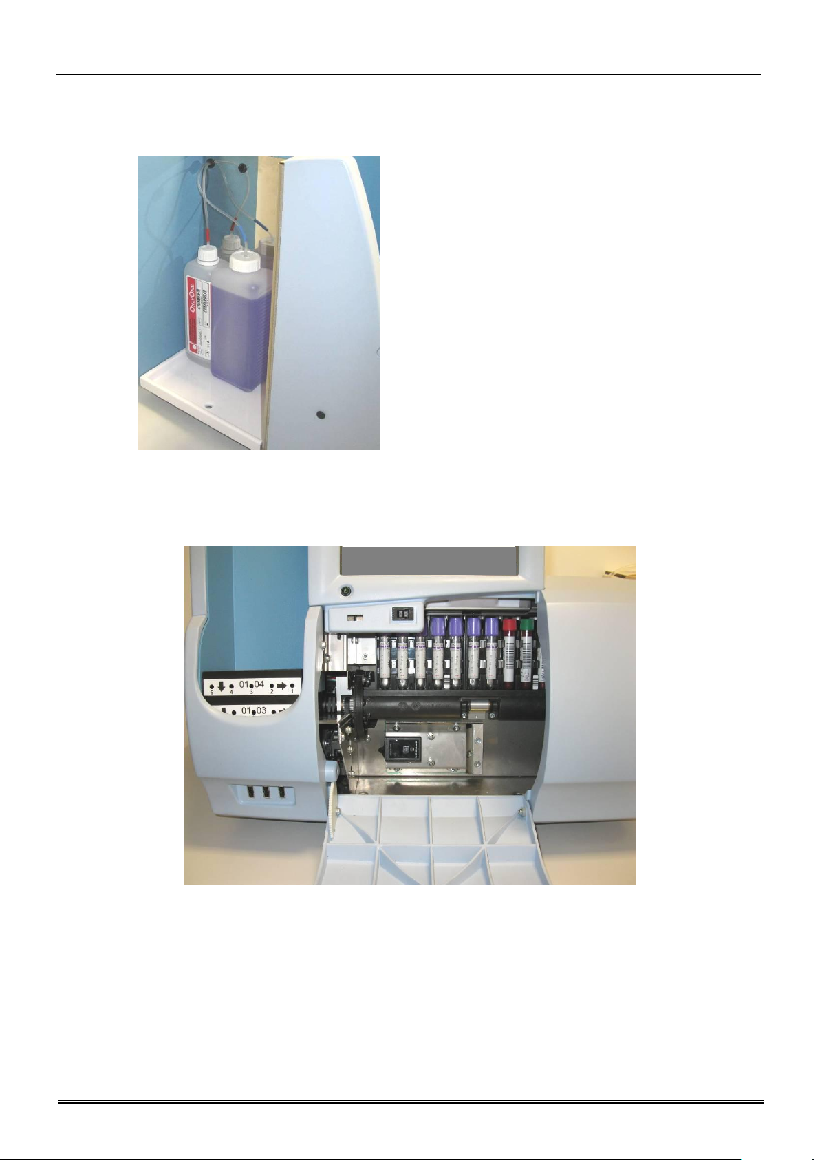
2.4.4 Reagent tray
The reagent tray is dedicated to the OnlyOne lysing reagent and cleaning solution bottles.
2.4.5 Sampler
- This module enables to load, transfer, mix and unload the racks. Ten racks of five tubes can be loaded. The
loading can be done continually.
- The rack are loaded on the guide rail by a loading screw then displaced by another screw (transfer screw).
- The rail which maintains the rack can also rotated for mixing the blood inside the tubes.
- When all the samplings are performed for a rack, it is unloaded by the unloading motor.
3. INSTRUMENT SET UP
REF : M22AL/UM/EN/004
Page 28/109
Copyright© Orphee SA. All Rights Reserved.
MYTHIC 22 AL
3. INSTRUMENT SET UP
3.1 USER’S IDENTIFICATION
3.1.1 Start Up Machine
- After the instrument’s initialization, the identification
window is displayed.
- In the window , the last
operator’s identification appears.
- Either the identification is yours, press
identification is not, enter your login with the keyboard.
- The window enables to change the
language.
- To validate or not the modification, see section 8.7.1.
- AUTONOMY (run) indicates the number of samples (runs)
you can perform (calculated with the smaller quantity of
reagents).
- Enter your identification name with the alphabetic keyboard.
- Place the cursor in the Password window.
- Enter your password for identification.
- For the first login, MYTHIC 22 AL proposes 3 access levels:
o User : No password
o Biologist : Password by default 1- 2- 3
o Service people
- Biologist Password can be modified in section 3.3.6.
3.1.2 In process
- To change operator during the process, press to
return to the main menu, and then press on
- To change identification, proceed as described above
(section 3.1.1).
and enter your password or the
REF : M22AL/UM/EN/004
3. INSTRUMENT SET UP
MYTHIC 22 AL
Copyright© Orphee SA. All Rights Reserved.
Page 29/109
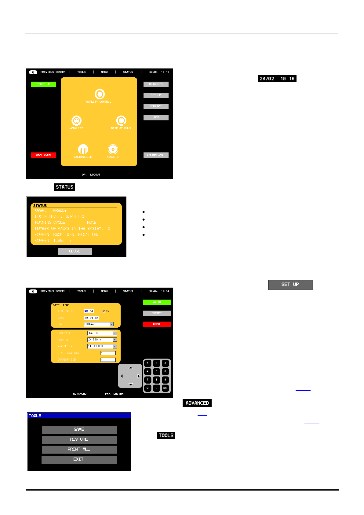
3.2 SYSTEM STATUS
- Press on the date and hour to have access
to the system information window.
- Press on to have access to the status of the MYTHIC 22 AL.
- Different information are displayed:
Name of the operator
Level of access
Name of the cycle in progress
Number of racks
3.3 SET UP
- From the MAIN MENU press on
- This menu is available for all users.
- The DATE & TIME window enables to modify the time, the
date and the day.
- To select the language of the Mythic menu, choose the right
one in the LANGUAGE combo box.
- PRINTER: Select the printer or no printing.
- PAPER SIZE: Select the paper size per result.
- Two SID are available;
START DAY SID enables to select the first SID for
each new day.
CURRENT SID enables to fix the beginning of the
current SID number (which will be used in the AUTO
SID number in the work list, see section 5.6.2)
- : Biologist reserved for complete settings. (See
section 3.4).
- To validate or not the modification, see section 8.7.1.
- Press to save, load (RESTORE), print or delete all the settings, from
an USB key. Three pages are required to print all the settings.
 Loading...