

Page 1

VersaSync
User Manual
Document Part No.: 1228-5000-0050
Revision: 7.0
Date: 5-August-2019
orolia.com
Page 2

Page 3

© 2019 Orolia. All rights reserved.
The information in this document has been carefully reviewed and is believed to
be accurate and up-to-date. Orolia assumes no responsibility for any errors or
omissions that may be contained in this document, and makes no commitment
to keep current the information in this manual, or to notify any person or organization of updates. This User Manual is subject to change without notice. For
the most current version of this documentation, please see our web site at
orolia.com.
Orolia reserves the right to make changes to the product described in this document at any time and without notice. Any software that may be provided with
the product described in this document is furnished under a license agreement
or nondisclosure agreement. The software may be used or copied only in accordance with the terms of those agreements.
No part of this publication may be reproduced, stored in a retrieval system, or
transmitted in any form or any means electronic or mechanical, including photocopying and recording for any purpose other than the purchaser's personal
use without the written permission of Orolia.
Other products and companies referred to herein are trademarks or registered
trademarks of their respective companies or mark holders.
Orolia USA, Inc. dba Spectracom
• 1565 Jefferson Road, Su ite 460, Rochester, NY 14623 USA
• 3, A venu e du Canada, 91974 Les U lis Cedex, France
The industry-leading Spectracom products you depend on are now brought to
you by Orolia, the global leader in Resilient Positioning, Navigation and Timing
Solutions.
Do you have questions or comments regarding this User Manual ?
è E-mail: techpubs@orolia.com
Warranty Information
For a copy of Orolia's Limited Warranty policy, see the website:
http://www.orolia.com/support/spectracom/warranty-information.
VersaSync User Manual I
Page 4

Blank page.
II VersaSync User Manual
Page 5

CHAPTER 1
Product Description
1.1 Getting Started
1.2 VersaSync Overview
1.3 Status LEDs
1.3.1 Blinking Intervals
1.3.2 LED Lighting Patterns
1.3.3 Legend, individual LEDs
1.3.3.1 LED Patterns during Boot Sequence
1.3.4 Blackout Mode
1.4 Interfaces Overview
1.4.1 Input Timing Interfaces
1.4.2 Output Timing Interfaces
1.4.3 Other Interfaces
1.5 Connectors and their Pinouts
1.5.1 Power Connector
1.5.2 Input/Output Connector
1.5.3 Ethernet Connector
1.5.4 Optional I/O Connector
1.5.5 Coaxial Connectors
1.5.5.1 ODU® ordering contact information(USA):
1
2
2
4
4
4
5
6
6
6
7
8
8
9
9
10
11
11
12
12
CONTENTS
1.6 Included Cables
1.7 VersaSync Specifications
1.7.1 Supply Power
1.7.2 GNSS Receiver
1.7.3 Mechanical & Environmental Specifications
1.7.3.1 PhysicalSpecifications
1.7.3.2 Environmental Requirements
1.8 Regulatory Compliance
1.9 The VersaSync Web UI
1.9.1 The Web UI HOME Screen
VersaSync User Manual • TABLE OF CONTENTS
14
16
16
16
17
17
17
18
19
19
III
Page 6

1.9.2 The INTERFACES Menu
1.9.3 The Configuration MANAGEMENT Menu
1.9.4 The TOOLS Menu
CHAPTER 2
20
21
22
SETUP
2.1 SAFETY
2.1.1 SAFETY: Before You Begin Installation
2.1.2 SAFETY: User Responsibilities
2.1.3 SAFETY: Other Tips
2.2 Installation Overview
2.2.1 Hardware Connections
2.2.2 Mounting
2.2.2.1 Selectinga MountingLocation
2.2.2.2 Heat Dissipation
2.2.2.3 Fasteners
2.2.2.4 Grounding
2.3 Initial Network Setup
2.3.1 USB Driver
2.3.2 Network Connection
2.4 Accessing the WebUI
2.5 Zero Configuration Setup
2.5.1 Using Zeroconf
23
24
24
25
26
26
26
28
28
29
29
29
29
30
30
32
34
35
IV
2.6 Setting up an IP Address
2.6.1 Assigning a Static IP Address
2.7 Configuring Inputs/Outputs
2.7.1 Assigning I/O Pins
2.7.1.1 Signal Types
2.7.1.2 I/O Signal Mapping Table
2.7.2 Configure I/O Input and Output Settings
2.7.2.1 How toConfigurean Input Reference
2.7.2.2 How to Configure an Output
2.7.3 Example: Configuring a 20 PPS Output
2.7.4 Configurable I/Os
2.7.4.1 Configuring a 1PPS Input
2.7.4.2 Configuringa 1PPS Output
VersaSync User Manual • TABLE OF CONTENTS
35
36
38
39
40
40
44
44
45
45
47
47
48
Page 7

2.7.4.3 Configuring an ASCII Input
2.7.4.4 Configuring an ASCII Output
2.7.4.5 Event Broadcast (ASCII Output)
2.7.4.6 Configuring a HaveQuick Input
2.7.4.7 Configuringa HaveQuick Output
2.7.5 Signature Control
49
51
54
57
59
60
2.8 Configuring Network Settings
2.8.1 General Network Settings
2.8.2 Network Ports
2.8.3 Network Services
2.8.4 Access Rules
2.8.5 HTTPS
2.8.5.1 Accessing the HTTPS Setup Window
2.8.5.2 About HTTPS
2.8.5.3 SupportedCertificate Formats
2.8.5.4 Creating an HTTPS Certificate Request
2.8.5.5 Adding HTTPS SubjectAlternative Names
2.8.5.6 Requestingan HTTPS Certificate
2.8.5.7 Uploadingan X.509 PEM Certificate Text
2.8.5.8 Uploadingan HTTPS Certificate File
2.8.6 SSH
2.8.7 SNMP
2.8.7.1 SNMP V1/V2c
2.8.7.2 SNMP V3
2.8.7.3 SNMP Traps
2.8.8 System Time Message
2.8.8.1 System Time Message Format
2.8.9 Configure NTP
2.8.9.1 Checklist NTP Configuration
2.8.9.2 The NTP Setup Screen
2.8.9.3 Dis-/Enabling NTP
2.8.9.4 Viewing NTP Clients
2.8.9.5 Restoring the Default NTP Configuration
2.8.9.6 NTP OutputTimescale
2.8.9.7 NTP Reference Configuration
2.8.9.8 NTP Servers and Peers
2.8.9.9 NTP Authentication
2.8.9.10 NTP Access Restrictions
62
63
64
66
67
68
69
70
71
71
74
75
77
78
79
86
90
92
94
96
97
98
98
99
101
102
103
104
105
107
114
123
VersaSync User Manual • TABLE OF CONTENTS
V
Page 8

2.8.9.11 NTP Expert Mode
2.8.9.12 Orolia Technical Support for NTP
2.8.10 Configuring PTP
2.8.10.1 The PTPScreen
2.8.10.2 Enabling/DisablingPTP
2.8.10.3 Configuration — General Steps
2.8.11 GPSD Setup
CHAPTER 3
125
128
129
129
133
133
133
Managing Time
3.1 The Time Management Screen
3.2 System Time
3.2.1 System Time
3.2.1.1 Configuring the System Time
3.2.1.2 Timescales
3.2.1.3 Manually Settingthe Time
3.2.1.4 Using Battery Backed Time onStartup
3.2.2 Timescale Offset(s)
3.2.2.1 Configuring a Timescale Offset
3.2.3 Leap Seconds
3.2.3.1 Reasons for a Leap SecondCorrection
3.2.3.2 Leap Second AlertNotification
3.2.3.3 Leap Second Correction Sequence
3.2.3.4 Configuring a Leap Second
3.2.4 Local Clock(s), DST
3.2.4.1 Adding a Local Clock
3.2.4.2 DST Examples
3.2.4.3 DST andUTC, GMT
135
136
137
138
138
139
141
143
145
145
146
146
147
148
148
149
149
151
152
VI
3.3 Managing References
3.3.1 Input Reference Priorities
3.3.1.1 Configuring Input Reference Priorities
3.3.1.2 The "Local System" Reference
3.3.1.3 The "User/User" Reference
3.3.1.4 Reference Priorities: EXAMPLES
3.3.2 Reference Qualification and Validation
3.3.2.1 BroadShield
3.3.3 The GNSS Reference
VersaSync User Manual • TABLE OF CONTENTS
153
153
154
157
158
160
164
164
171
Page 9

3.3.3.1 Reviewing the GNSS ReferenceStatus
3.3.3.2 Determining Your GNSS ReceiverModel
3.3.3.3 Selecting a GNSS ReceiverMode
3.3.3.4 Setting GNSS Receiver Dynamics
3.3.3.5 Performing a GNSS Receiver Survey
3.3.3.6 GNSS Receiver Offset
3.3.3.7 Resetting the GNSS Receiver
3.3.3.8 Deleting the GNSS ReceiverPosition
3.3.3.9 Manually Setting the GNSS Position
3.3.3.10 GNSS Constellations
3.3.4 Holdover Mode
172
177
178
180
183
184
185
186
188
190
193
3.4 Managing the Oscillator
3.4.1 Configuring the Oscillator
3.4.1.1 Time Figure of Merit (TFOM)
3.4.2 Monitoring the Oscillator
3.4.3 Oscillator Logs
CHAPTER 4
System Administration
4.1 Issuing the HALT Command Before Removing Power
4.2 Rebooting the System
4.3 Notifications
4.3.1 Configuring Notifications
4.3.2 Notification Event Types
4.3.2.1 Timing Tab: Events
4.3.2.2 GPS Tab: Events
4.3.2.3 System Tab: Events
4.3.3 Configuring GPS Notification Alarm Thresholds
4.3.4 Setting Up SNMP Notifications
4.3.5 Setting Up Email Notifications
197
198
200
201
204
207
208
209
209
210
213
213
213
214
214
215
216
4.4 Managing Users and Security
4.4.1 Managing User Accounts
4.4.1.1 Types ofAccounts
4.4.1.2 About "user" AccountPermissions
4.4.1.3 Rules for Usernames
4.4.1.4 Adding/Deleting/Changing User Accounts
VersaSync User Manual • TABLE OF CONTENTS
218
218
218
218
220
220
VII
Page 10

4.4.2 Managing Passwords
4.4.2.1 ConfiguringPasswordPolicies
4.4.2.2 The Administrator Password
4.4.2.3 Lost Password
4.4.3 Web UI Timeout
223
223
224
225
227
4.5 Miscellanous Typical Configuration Tasks
4.5.1 REST API Configuration
4.5.2 Creating a Login Banner
4.5.3 Show Clock
4.5.4 Synchronizing Network PCs
4.6 Quality Management
4.6.1 System Monitoring
4.6.1.1 Status Monitoring via theWeb UI
4.6.1.2 Ethernet Monitoring
4.6.1.3 Monitoring the Oscillator
4.6.1.4 NTP Status Monitoring
4.6.2 Logs
4.6.2.1 Types of Logs
4.6.2.2 The Logs Screen
4.6.2.3 Displaying Individual Logs
4.6.2.4 Saving and DownloadingLogs
4.6.2.5 Settingup a Remote Log Server
4.6.2.6 Clearing AllLogs
4.7 Updates and Licenses
4.7.1 Software Updates
4.7.2 Applying a License File
227
227
228
229
230
230
230
230
233
234
237
242
243
247
248
249
250
252
252
252
254
VIII
4.8 Resetting the Unit to Factory Configuration
4.8.1 Resetting All Configurations to their Factory Defaults
4.8.2 Backing-up and Restoring Configuration Files
4.8.2.1 Accessing the System Configuration Screen
4.8.2.2 Saving the System ConfigurationFiles
4.8.2.3 Uploading Configuration Files
4.8.2.4 Restoringthe System Configuration
4.8.2.5 Restoring the Factory Defaults
4.8.3 Cleaning the Configuration Files and Halting the System
4.8.4 Default and Recommended Configurations
VersaSync User Manual • TABLE OF CONTENTS
255
255
256
256
258
259
260
261
261
261
Page 11

APPENDIX
Appendix
5.1 Troubleshooting
5.1.1 Minor and Major Alarms
5.1.2 Troubleshooting: System Configuration
5.1.2.1 System Troubleshooting: Browser Support
5.1.3 Troubleshooting – Unable to Open Web UI
5.1.4 Troubleshooting via Web UI Status Page
5.1.5 Troubleshooting GNSS Reception
5.1.6 Troubleshooting – 1PPS, 10 MHz Outputs
5.1.7 Troubleshooting – Network PCs Cannot Sync
5.1.8 Troubleshooting Software Update
5.2 Command-Line Interface
5.2.1 Setting up a Terminal Emulator
5.2.2 CLICommands
5.3 Time Code Data Formats
5.3.1 NMEA GGA Message
5.3.2 NMEA RMC Message
5.3.3 NMEA ZDA Message
5.3.4 ASCII Output Settings
5.3.4.1 VNYPR
5.3.4.2 VNQTN
5.3.4.3 VNQMR
5.3.4.4 VNMAG
5.3.4.5 VNACC
5.3.4.6 VNGYR
5.3.4.7 VNMAR
5.3.4.8 VNYMR
5.3.4.9 VNYBA
5.3.4.10 VNYIA
5.3.4.11 VNIMU
5.3.4.12 VNGPS
5.3.4.13 VNGPE
5.3.4.14 VNINS
5.3.4.15 VNINE
5.3.4.16 VNISL
5.3.4.17 VNI SE
263
264
264
264
265
265
266
267
268
269
270
271
271
272
277
277
278
278
279
279
280
281
282
282
283
284
285
286
286
287
288
289
291
293
296
297
VersaSync User Manual • TABLE OF CONTENTS
IX
Page 12

5.3.4.18 VNDTV
5.3.4.19 VNG2S
5.3.4.20 VNG2E
5.3.5 Spectracom Format 0
5.3.6 Spectracom Format 1
5.3.7 Spectracom Format 1S
5.3.8 Spectracom Format 2
5.3.9 Spectracom Format 3
5.3.10 Spectracom Format 4
5.3.11 Spectracom Format 7
5.3.12 Spectracom Format 8
5.3.13 Spectracom Format 9
5.3.13.1 Format 9S
5.3.14 Spectracom Epsilon Formats
5.3.14.1 Spectracom Epsilon TOD1
5.3.14.2 Spectracom Epsilon TOD3
5.3.15 BBC Message Formats
5.3.15.1 Format BBC-01
5.3.15.2 Format BBC-02
5.3.15.3 Format BBC-03 PSTN
5.3.15.4 Format BBC-04
5.3.15.5 Format BBC-05 (NMEA RMC Message)
5.3.16 GSSIP Message Format
5.3.17 EndRun Formats
5.3.17.1 EndRun Time Format
5.3.17.2 EndRunX (Extended) Time Format
5.3.18 Event Broadcast Time Code Formats
5.3.18.1 Event Broadcast Format 0
5.3.18.2 Event Broadcast Format 1
298
300
301
303
304
306
307
310
311
313
314
316
316
317
317
318
318
318
319
321
322
323
324
325
325
326
327
327
328
5.4 IRIG Standards and Specifications
5.4.1 About the IRIG Output Resolution
5.4.2 IRIG Carrier Frequencies
5.4.3 IRIG B Output
5.4.4 IRIG E Output
5.4.5 IRIG Output Accuracy Specifications
5.5 Subnet Mask Values
5.6 Product Registration
X
VersaSync User Manual • TABLE OF CONTENTS
328
328
329
333
337
341
342
343
Page 13

5.7 TechnicalSupport
5.7.1 Regional Contact
343
344
5.8 Return Shipments
5.9 License Notices
5.10 List of Tables
5.11 List of Images
5.12 Document Revision History
INDEX
5.9.1 NTPv4.2.8p12
5.9.2 OpenSSH
5.9.3 OpenSSL
344
345
345
349
352
356
358
358
VersaSync User Manual • TABLE OF CONTENTS
XI
Page 14

BLANK PAGE.
XII
VersaSync User Manual • TABLE OF CONTENTS
Page 15

Product Description
The Chapter presents an overview of the VersaSync Time and
Frequency Synchronization System, its capabilities, main technical features and specifications.
The following topics are included in this Chapter:
1.1 Getting Started 2
1.2 VersaSync Overview 2
1.3 Status LEDs 4
1.4 Interfaces Overview 6
1.5 Connectors and their Pinouts 9
1.6 Included Cables 14
1.7 VersaSync Specifications 16
1.8 Regulatory Compliance 18
1.9 The VersaSync Web UI 19
CHAPTER 1
CHAPTER 1 • VersaSync User Manual
1
Page 16
1.1 Getting Started
1.1 Getting Started
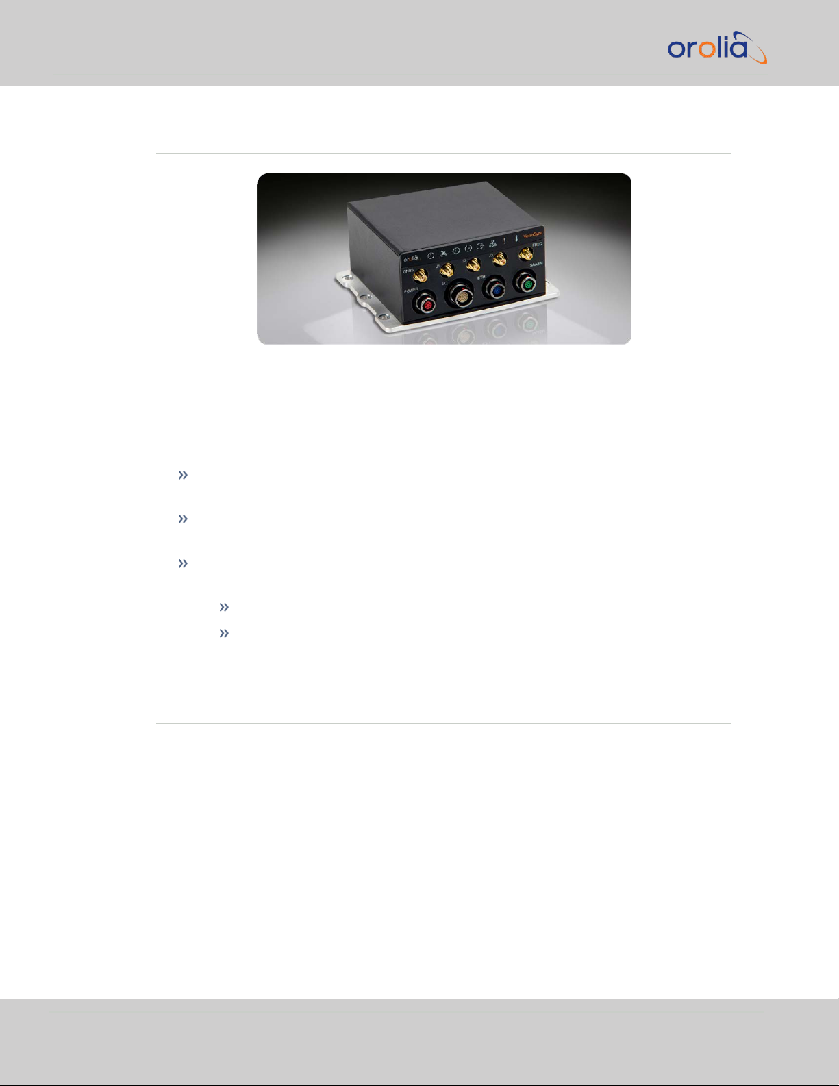
Figure 1-1: VersaSync Rugged GPS Time & Frequency Reference
Welcome to the VersaSync User Manual .
First steps:
If you are not yet familiar with VersaSync, you may want to start here: "VersaSync
Overview" below.
If you are ready to begin the installation process, see: "Initial Network Setup" on
page29
If your unit is already up and running, and you would like to change specific settings,
see …
… "Managing Time" on page135, or
… "System Administration" on page207.
1.2 VersaSync Overview
VersaSync is a high-performance time & frequency GPS master clock and network time
server that delivers accurate, software configurable time and frequency signals under all circumstances, including GNSS-denied environments. Its compact size and high level of ruggedization make VersaSync suitable for mobile applications in harsh environments.
VersaSync's small footprint allows for easy integration of the time and frequency functionality into systems architecture.
VersaSync includes all the timing functionality required in modern, network-centric applications:
2
CHAPTER 1 • VersaSync User Manual Rev. 7.0
Page 17

1.2 VersaSync Overview
NTP/PTP precise time transfer over Ethernet, including security protocols that prevent network vulnerabilities
Low phase noise 10 MHz frequency distribution
Configurable pulse signals, including IRIG or HaveQuick timecodes
Serial link Time Of Day (ToD) messages
GPS-Denied Environments
VersaSync accommodates an OCXO oscillator, allowing the unit to maintain frequency and
time accuracy for long periods of GPS/GNSS outage. In addition, it can be re-synchronized
by an external reference.
Reliable, Versatile, and Configurable
VersaSync physical inputs and outputs are software configurable and can adapt to various
application requirements. I/O pins can be configured as TTL, 10 V pulse, RS232, RS422,
and RS485. This allows VersaSync to provide a high number of outputs of the same type,
while still fitting into a small form factor. However, if the combination of software configurable outputs is not enough, VersaSync can accommodate an option board (within the
same form factor), designed to customer requirements to provide additional outputs of the
same type orother type of interface (IRIG AM, etc…).
Due to its high level of ruggedization, VersaSync provides very high intrinsic reliability.
Strong status monitoring capability, either locally or remotely, allows quick fault diagnosis.
Physical alarm (dry contact) and network alarms (SNMP traps) are raised in real time. An
internal, exportable log can be accessed either locally or remotely. In addition to oscillator
options (OCXO), VersaSync is available with a C/A L1 GPS receiver or with an L1/L2
SAASM receiver. Pulse outputs are configurable through the web user interface ("Web
UI"). An extension slot is available to accommodate additional timing interfaces.
Typical Applications
Airborne: Observation payload (radars, optronics, electronic warfare), flying test
bench, flight analysis
Ground: Satcom On the Move (SOTM), anti-IED jamming systems, mobile radios and
C3I, robotics
Marine: Sensor support (radars, sonars, optronics, electronic warfare), com-
munication networks, offshore/DSO platforms, buoys
CHAPTER 1 • VersaSync User Manual Rev. 7.0
3
Page 18
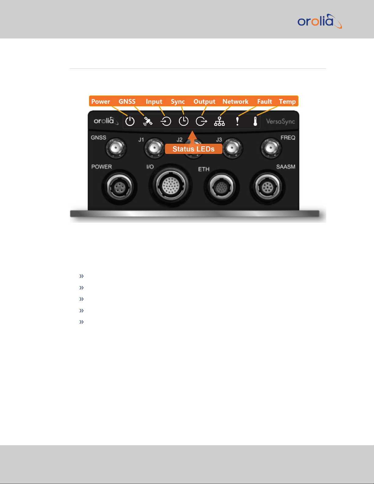
1.3 Status LEDs
1.3 Status LEDs
VersaSync's front panel status LEDs provide a real-time status overview: Eight (8) LEDs
indicate the unit's current operating state:
The LEDs can be disabled, see "Blackout Mode" on page6.
1.3.1 Blinking Intervals
The statusLEDs can communicate five different operating states:
"OFF"
"ON"
"FAST": blinking interval @ 8Hz
"SLOW": blinking interval @ 2Hz
"HEARTBEAT": sinus-shaped interval @ 1Hz
1.3.2 LED Lighting Patterns
The table below indicates LED status light patterns for common VersaSync operating
statuses.
4
CHAPTER 1 • VersaSync User Manual Rev. 7.0
Page 19

Start-up HEARTB. OFF OFF OFF OFF OFF OFF OFF
Acquiring fix
FAST FAST FAST FAST FAST FAST HEARTB. FAST
Software
upgrade
FAST OFF OFF FAST OFF FAST HEARTB. OFF
Icon Light Meaning
OFF No power
HEARTBEAT Booting
ON Powered
OFF No GNSS reception (0 satellites)
HEARTBEAT GNSS acquisition in process (≥ 1satellite(s), or 1PPS OK, or Time OK
SLOW Jamming detected
FAST Antenna short circuit
ON GNSS is available as reference (1PPS and Time OK)
OFF Inputs not detected/all inputs are disabled
FAST 1 or more input is missing, or invalid timing on 1 or more input detec-
ted
ON Inputs are enabled
OFF Unit is in Holdover (valid)
ON System Clock OK (valid)
FAST Invalid Time (Holdover period exceeded, or oscillator damaged)
OFF No output signal(s) detected/all outputs are disabled
FAST Malfunction detected (short circuit, or overload)
ON Outputs are enabled
1.3 Status LEDs
Table 1-1:
Common light patterns
1.3.3 Legend, individual LEDs
Table 1-2:
Legend for Status LEDs
CHAPTER 1 • VersaSync User Manual Rev. 7.0
5
Page 20
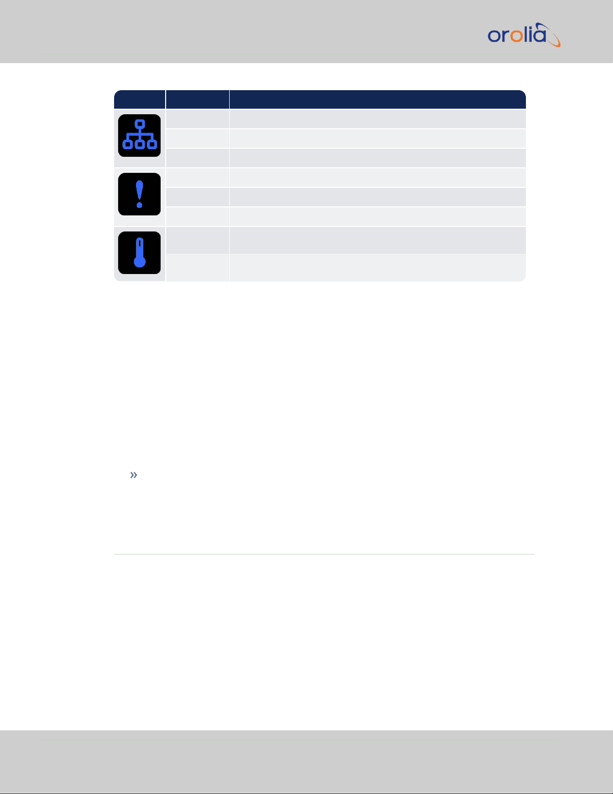
Icon Light Meaning
OFF No network detected
FAST Network malfunction detected (e.g., no auto-negotiation)
ON Network OK, configuration OK
OFF Unit OK
FAST Unit requires attention; check other status LEDs, see Web UI
HEARTBEAT See table
"LED Lighting Patterns" on page4
OFF Temperature OK
FAST High temperature detected
1.4 Interfaces Overview
1.3.3.1 LED Patterns during Boot Sequence
For the first five seconds after power-up all LEDs will be OFF. Then the Power LED will be
blinking before it will be lit permanently. If you have configured your unit to operate in
Blackout Mode, this will take effect once the blinking cycle ends.
1.3.4 Blackout Mode
All LEDs can be turned off via the WebUI.
The LED brightness level can be set from 63 (as bright as possible) to 0 (not visable).
To disable all LED activity via the WebUI:
Navigate to MANAGEMENT > OTHER: LED Configuration, and set the Brightness
level to "0".
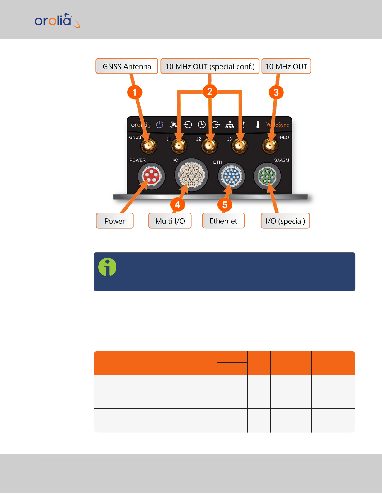
1.4 Interfaces Overview
All of VersaSync's interfaces are integrated into the unit's connectors, which are located on
the front panel:
6
CHAPTER 1 • VersaSync User Manual Rev. 7.0
Page 21
INPUTSIGNAL
Total
available
DCLS
RS-
232
RS-
485
ETH
Connector No.
(see Fig.
above)
TTL 10V
1PPS (1) 1 4
ASCII/HaveQuick/IRIG B (1) 1 4
ASCII/NMEA (1) 1 4
Network Interface
(10/100/1000bT):
NTP (Stratum 2), PTP
(2) 1 5
1.4 Interfaces Overview
1.4.1 Input Timing Interfaces
Figure 1-2: VersaSync front panel connectors
Note: VersaSync is highly configurable and the connections can be adjusted
many different ways. Your interface configuration may vary based on
options you selected during the ordering process.
The following interfaces are provided:
Table 1-3:
VersaSync inputs (default setup)
CHAPTER 1 • VersaSync User Manual Rev. 7.0
7
Page 22

OUTPUTSIGNAL
Total
available
DCLS
RS- 232 RS-485 ETH
Connector No.
(see Fig. above)
TTL 10V
10 MHz (1+3) SMA
2,
3
1PPS (2) 1 1 4
ASCII/HaveQuick (1) 1 4
ASCII/NMEA (1) 1 4
NTP server,
PTP v2 master
(1) 1 5
1.4 Interfaces Overview
All Multi I/O interfaces (connector no. 4) are software-configurable, see "Assigning I/O
Pins" on page39.
1.4.2 Output Timing Interfaces
Table 1-4:
VersaSync outputs (default setup)
All Multi I/O interfaces (connector no. 4) are software-configurable, see "Assigning I/O
Pins" on page39.
For additional information on configuring pinouts, see "Connectors and their Pinouts" on
the facing page and "Configure I/O Input and Output Settings" on page44.
1.4.3 Other Interfaces
USB serial equivalent: CLI interface (Connector 4)
8
CHAPTER 1 • VersaSync User Manual Rev. 7.0
Page 23

1.5 Connectors and their Pinouts
Pin Signal
1 V
Main
(10 to 32V)
2 -not used-
3 V
Standby
(10 to 32 V)
4 GND (to Standby)
5 GND (to Main)
All of VersaSync's connectors are provided at the front panel of the unit, below the Status
LEDs. The Advanced Military Connectors are keyed for foolproof connectivity and offer a
push-pull locking mechanism.
1.5.1 Power Connector
1.5 Connectors and their Pinouts
Note: View in mating direction from front.
Table 1-5:
Power connector pinout
This product is designed to handle a maximum voltage of up to 32 VDC. Power supplies
with higher voltage or transient/ cranking power will require a power conditioner or surge
blocker.
Caution: Reversed polarity can blow an internal fuse that protects the
product from damage. Use care when building power cables.
CHAPTER 1 • VersaSync User Manual Rev. 7.0
9
Page 24

Pin Channel Signal Pin Channel Signal
1
0 1PPS output (5V)
15
7 Have Quick output
(RS-485 signal +)
2
GND
16
GND
3
1 HaveQuick input (RS-
485 signal +)
17
8 Have Quick output
(RS-485 signal –)
4
GND
18
GND
5
2 HaveQuick input (RS-
485 signal –)
19
9
(USB ded-
icated)
GND
6
GND
20
GND
7
3 1PPS output (10 V)
21
Not connected
8
GND
22
GND
9
4 ASCII output (RS-232)
23
USB D–
10
GND
24
GND
11
5 1PPS input
25
USB D+
12
GND
26
GND
13
6 ASCII input (RS-232)
14
GND
1.5 Connectors and their Pinouts
Test any new cables to safely power the unit before connecting your VersaSync to any
other inputs or outputs (such as a GNSS antenna), and before grounding your unit to a
vehicle.
1.5.2 Input/Output Connector
VersaSync has a 26- pin input/output connector that offers 8 software-configurable
CHANNELS, plus one fixed DCLS channel, and a USB interface. To learn more about types
of interfaces and signals, and how toconfigure them, see "Assigning I/O Pins" on page39.
Table 1-6:
Default I/O connector pinout
10
CHAPTER 1 • VersaSync User Manual Rev. 7.0
Page 25

1.5.3 Ethernet Connector
Pin Signal Pin Signal
1 Ethernet_1 A+ 9 Ethernet_2 A+
2 Ethernet_1 A– 10 Ethernet_2 A–
3 Ethernet_1 B+ 11 Ethernet_2 B+
4 Ethernet_1 B– 12 Ethernet_2 B–
5 Ethernet_1 C+ 13 Ethernet_2 C+
6 Ethernet_1 C– 14 Ethernet_2 C–
7 Ethernet_1 D+ 15 Ethernet_2 D+
8 Ethernet_1 D– 16 Ethernet_2 D–
Note: View in mating direction from front.
The Ethernet connector provides two 1GbE network connections, using 8 wires (pinout
below).
1.5 Connectors and their Pinouts
Table 1-7:
Ethernet connector pinout
It is also possible to wire your connector to 100MbE, using only 4 wires. Contact Tech Support for more information.
1.5.4 Optional I/O Connector
The Optional I/O connector is used in conjunction with the Option Board that is available
for VersaSync. If the unit is not equipped with an Option Board, this connector is not used.
CHAPTER 1 • VersaSync User Manual Rev. 7.0
11
Page 26
Ref Description
VersaSync Connector Mating (Cable) Connector
Spectracom
Part No.
ODU Part No.
Spectracom
Part No.
ODU Part No.
POWER Power connector,
5pin
J240R-0051-
002Q
GK1YBR-
P05UJ00-000L
P240R-0051-
002Q
S11YBRP05XJG0-0000
I/O I/O connector, 26
pin
J240R-0261-
002F
GK2YAR-
P26UC00-000L
P240R-0261-
002F
S12YARP26XCD0-0000
ETH Ethernet connector,
16 pin
J240R-0161-
002F
GK1YCR-
P16UC00-000L
P240R-0161-
002F
S11YCRP16XCD0-0000
SAASM Optional I/O con-
nector, 8 pin
J240R-0081-
012F
GK1YDR-
P08UF00-000L
P240R-0081-
002F
S11YDRP08XFG0-0000
1.5 Connectors and their Pinouts
1.5.5 Coaxial Connectors
VersaSync offers five (5) coaxial connectors, three (3) of which can be configured at the
factory to accommodate requirements for e.g., IRIG AM signals or additional 10MHz outputs. The minimum configuration includes the GNSS antenna and a 10MHz sinewave out-
put.
Unless otherwise ordered at the factory, all coaxial connectors (aside from the GNSS connection) produce a 10MHz output that is not software configurable.
All coaxial connectors are standard SMA connectors.
Mating Connector Plugs
The table below lists the part numbers for the mating connectors. The connectors can be
ordered through Spectracom or ODU-USA Inc. All connectors are circular ODU AMC
"mil-type" connectors.
®
1.5.5.1 ODU®ordering contact information (USA):
Table 1-8:
Connector Part Numbers
ODU-USA Inc.
4010 Adolfo Road
Camarillo, CA 93012
United States of America
Phone: +1 (805) 484 0540
Fax: +1 (805) 484 7458
Email: sales@odu-usa.com
12
CHAPTER 1 • VersaSync User Manual Rev. 7.0
Page 27

Note: Building the mating cables requires special tools. Contact ODU for
cable assemblies. Be advised that typical lead times are 12 to 16 weeks.
ETHERNET connector wiring:
1 through 8: A Ethernet Connect, 4 pairs, 1000bT
9 through 16: B Ethernet Connect, 4 pairs, 1000bT
POWER connector pinout
1.5 Connectors and their Pinouts
1: V
2: -not used-
3: V
4: Ground return, standby power
5: Ground return, main power
, 10 to 32 V
Main
Standby
DC
, 10 to 32 VDC(Standby Power)
CHAPTER 1 • VersaSync User Manual Rev. 7.0
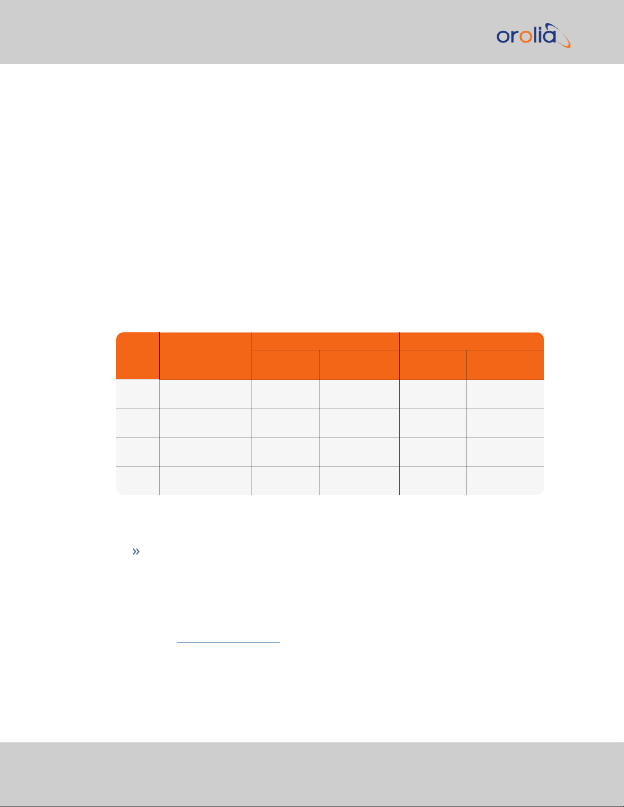
13
Page 28
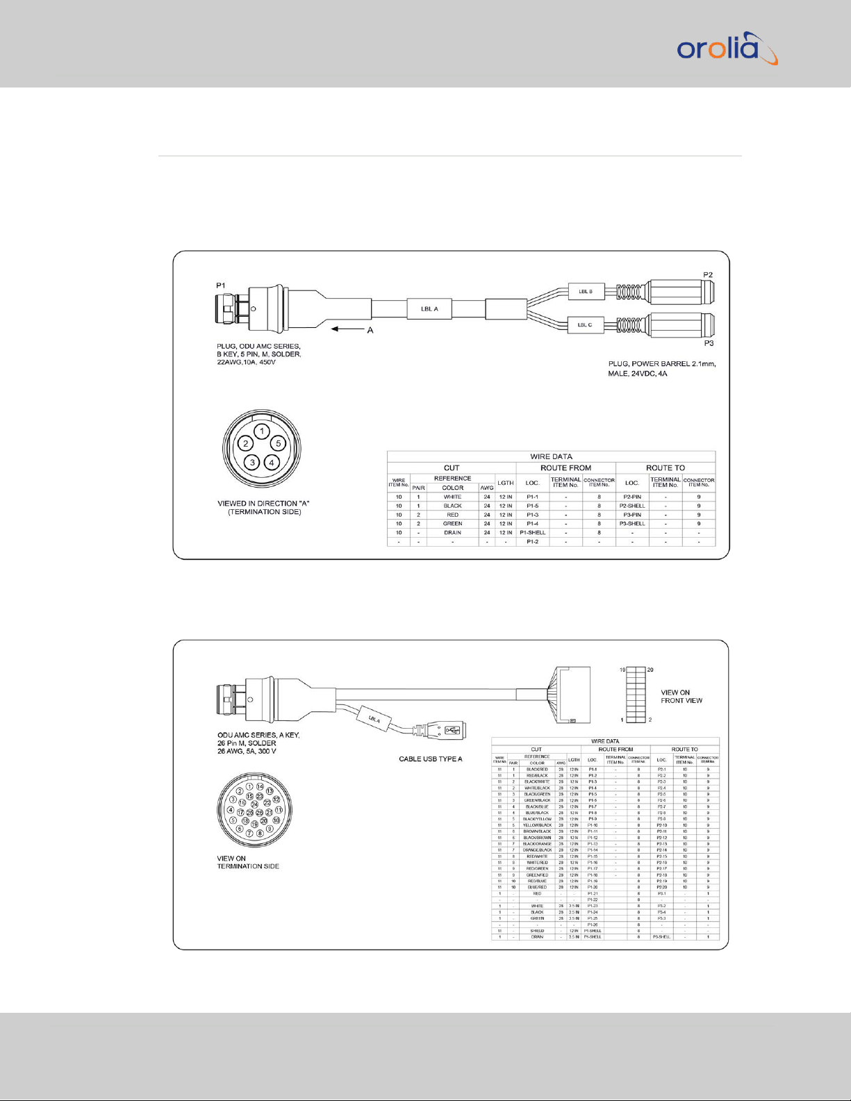
1.6 Included Cables
1.6 Included Cables
The VersaSync Evaluation Kit contains the following cables (antenna cable not shown):
Power Cable
I/O Cable
14
CHAPTER 1 • VersaSync User Manual Rev. 7.0
Page 29

I/O Breakout Cable
1.6 Included Cables
Ethernet Data Cable
CHAPTER 1 • VersaSync User Manual Rev. 7.0
15
Page 30

1.7 VersaSync Specifications
1.7 VersaSync Specifications
The specifications listed below apply to the current base model, during “normal” operation,
with VersaSync synchronized to valid Time and 1PPS input references.
1.7.1 Supply Power
Operating Power and Standby Power: 10 to 32 V
Power draw:
Operating: 10 W typical
Standby: 0.4W
This product is not intended to operate above 32VDC; power sources with transient
voltage spikes and surges above 32V require an external power conditioner/power filter to
ensure safe operation.
1.7.2 GNSS Receiver
VersaSync has an integrated state-of-the-art GNSS receiver, suitable for concurrent dualconstellation reception.
Compatible signals:
GPS L1 C/A (center frequency 1575.42 MHz)
GLONASS L10F (center frequency 1602.0 MHz)
Galileo E1 B/C (center frequency 1575.42 MHz)
QZSS L1-SAIF (center frequency 1575.42 MHz)
BeiDou B1 (center frequency 1561.098 MHz)
DC
16
Satellites tracked: Up to 72 simultaneously
Update rate: up to 2Hz (concurrent)
Acquisition time: Typically <27seconds from cold start
Antenna requirements: Active antenna module, +5V, powered by VersaSync, 16dB gain
minimum
Antenna connector: SMA
CHAPTER 1 • VersaSync User Manual Rev. 7.0
Page 31

1.7.3 Mechanical & Environmental Specifications
1.7.3.1 Physical Specifications
Dimensions (W x D x H): 147.3x 127.5 x 63.0 mm (5.8 x 5x 2.5 in)
1.7 VersaSync Specifications
Figure 1-3: Mechanical dimensions
Mounting: Bolted to a metal plate, using 6 through holes
Weight: 0.91 kg (2.0 lbs)
1.7.3.2 Environmental Requirements
Temperature, in operation: -40°C to +71°C
Temperature, in storage: -45°C to +85°C
Humidity: 95% RH, non condensing at 40°C
Altitude: up to 45,000 ft
CHAPTER 1 • VersaSync User Manual Rev. 7.0
17
Page 32

1.8 Regulatory Compliance
Protection: IP 65
Vibration:
7.7 g rms, 20 to 1000 Hz (in accordance with MIL-STD 810G, Method 214.6
Category 24: Minimum Integrity and Helicopter Minimum Integrity, see
graphs 514.7E-1 and 514.7E-2)
Shock: 20 g, 11 ms (pulse sawtooth) in accordance with MIL-STD 810G, Method
516.7 Procedure1
1.8 Regulatory Compliance
While the Evaluation Kit (EVK) of this product has not been tested against all standards
below, the production version is planned to be in compliance with the following regulatory
publications:
MIL compliance
Tested in accordance with MIL-STD-810G:
MIL-STD 810G, 506.6
MIL-STD 810G, 509.6
MIL-STD 810G, Method 516.7
MIL-STD 810G, Method 514.7 E1 and E2
MIL-461F Testing (EMI/EMC):
MIL-STD-461F CE102 Conducted Emissions, Power Leads
Note: Frequency Range: 10kHz to 10MHz; Test Limits: Figure CE1021
MIL-STD-461F CS101 Conducted Susceptibility, Power Leads
Note: Frequency: 30Hz to 150kHz; Test Levels: Figure CS101- 1
(Curve #2)
MIL-STD-461F RE102 Radiated Emissions, Electric Field
Note: Frequency Range: 10kHz to 18GHz; Test Limits: Figure RE1023
MIL-STD-461F CS114 Conducted Susceptibility, Bulk Cable Injection
Note: Frequency Range: 10kHz to 200MHz
18
FCC compliance
CHAPTER 1 • VersaSync User Manual Rev. 7.0
Page 33

1.9 The VersaSync Web UI
This equipment has been tested and found to comply with the limits for a ClassA digital
device, pursuant to Part15 of the FCC Rules.
These limits are designed to provide reasonable protection against harmful interference
when the equipment is operated in a commercial environment. This equipment generates, uses, and can radiate radio frequency energy and, if not installed and used in accordance with the user documentation, may cause harmful interference to radio
communications.
Operation of this equipment in a residential area is likely to cause harmful interference
in which case the user will be required to correct the interference at his/her own expense.
Other compliance
EN 60068-2-6
RoHS, WEEE compliant.
1.9 The VersaSync Web UI
VersaSync has an integrated web user interface (referred to as "WebUI" throughout this
documentation) that can be accessed from a network-connected computer, using a standard web browser. The WebUI is the most complete way to configure and monitor the unit.
Note: If you prefer, an integrated Command-Line Interpreter interface
(CLI) allows the use of a subset of commands. See "Command-Line Inter-
face" on page271.
1.9.1 The Web UI HOME Screen
Note: Screens displayed in this manual are for illustrative purposes. Actual
screens may vary depending upon the configuration of your product.
The HOME screen of the VersaSync web user interface ("Web UI") provides comprehensive status information at a glance, including:
vital system information
current status of the references
key performance/accuracy data
major log events.
CHAPTER 1 • VersaSync User Manual Rev. 7.0
19
Page 34

1.9 The VersaSync Web UI
The HOMEscreen can be accessed from anywhere in the Web UI, using the HOMEbutton
in the Primary Navigation Bar:
The Primary Navigation Bar provides access to all menus:
HOME: Return to the HOME screen (see above)
INTERFACES: Access the configuration pages for …
… references (e.g., GNSS, NTP)
… outputs (e.g. 10 MHz, PPS, NTP) and
… installed input/output option cards.
MANAGEMENT: Access the NETWORK setup screens, and OTHER setup screens
e.g., to configure Reference Priorities, System Time, and the Oscillator.
TOOLS: Opens a drop-down menu for access to the system maintenance screens
and system logs.
HELP: Provides Spectracom Service Contact Information and high-level system con-
figurations you may be required to furnish when contacting Orolia Service.
1.9.2 The INTERFACES Menu
The INTERFACES menu on the Main screen provides access to VersaSync's:
External REFERENCES e.g., the GNSS reference input
Detected OUTPUTS, such as 10 MHz and 1PPS
Installed OPTIONS.
20
CHAPTER 1 • VersaSync User Manual Rev. 7.0
Page 35

1.9 The VersaSync Web UI
Clicking on any of the line items will open a status screen, providing real-time information
on the selected interface e.g., availability, performance data and events history.
To configure settings for the selected interface, click the GEAR icons or buttons provided
on most of the status screens. Icons like the INFO symbol provide access to more detailed
status information and history data.
The headings of each of the INTERFACES drop-down menus (white on orange) open
overview status screens for the respective menu items.
1.9.3 The Configuration MANAGEMENT Menu
The MANAGEMENT menu on the Web UI's Main screen provides access to VersaSync's
configuration screens and settings.
On the left side, under NETWORK, the following standard setup screens can be found:
Pin Layout
Network Setup
SSH Setup
SNMP Setup
NTP Setup
PTP Setup
GPSD Setup
Under OTHER, you can access non-network related screens:
Authentication: Manage user accounts, Security Policy, LDAP Setup, RADIUS
setup, Login Preference and Remote Servers. Change My Password is also available.
Reference Priority: Define the order of priority for timing inputs.
CHAPTER 1 • VersaSync User Manual Rev. 7.0
21
Page 36

1.9 The VersaSync Web UI
Notifications: Configure the notifications triggered by VersaSync’s events. A noti-
fication can be a combination of a mask alarm and/or SNMP Trap and/or email.
Time Management: Manage the Local Clock, UTC Offset, DST Definition and Leap
Second information.
System Time Message: Configure a regularly delivered message of the system
time.
Log Configuration: Manage the system logs.
Disciplining: Manage oscillator disciplining.
LED Configuration: Change the LEDbrightness.
Change My Password: Configure the admin password.
1.9.4 The TOOLS Menu
The TOOLS menu on the Web UI's Main screen provides access to:
The System Upgrade screen
System and network monitoring screens
Miscellaneoussystem administration screens
Log screens
22
CHAPTER 1 • VersaSync User Manual Rev. 7.0
Page 37

SETUP
The following topics are included in this Chapter:
2.1 SAFETY 24
2.2 Installation Overview 26
2.3 Initial Network Setup 29
2.4 Accessing the WebUI 32
2.5 Zero Configuration Setup 34
2.6 Setting up an IP Address 35
2.7 Configuring Inputs/Outputs 38
2.8 Configuring Network Settings 62
CHAPTER 2
CHAPTER 2 • VersaSync User Manual
23
Page 38

2.1 SAFETY
2.1 SAFETY
Table 2-1:
Symbol Signal word Definition
Safety symbols used on this product or in this document
Potentially dangerous situation which may lead to per-
DANGER!
CAUTION!
NOTE
ESD
CHASSIS GROUND
Analog Ground
Recycle
sonal injury or death! Follow the instructions closely.
Potential equipment damage or destruction!
Follow the instructions closely.
Tips and other useful or important information.
Risk of Electrostatic Discharge!
Avoid potential equipment damage by following ESD Best
Practices.
This symbol is used for identifying the functional ground
of an I/O signal. It is always connected to the instrument
chassis.
Shows where the protective ground terminal is connected inside the instrument. Never remove or loosen
this screw!
Recycle the mentioned components at their end of life.
Follow local laws.
2.1.1 SAFETY: Before You Begin Installation
This product may constitute a risk to the operator or installation/maintenance personnel, if
used under conditions that must be deemed unsafe, or for purposes other than the
product's designated use, which is described in the introductory technical chapters of this
guide.
DANGER! If the equipment is used in a manner not specified by the man-
ufacturer, the protection provided by the equipment may be impaired.
Before you begin installing and configuring this product, carefully read the following important safety statements. Always ensure that you adhere to any and all applicable safety warnings, guidelines, or precautions during the installation, operation, and maintenance of your
product.
24
CHAPTER 2 • VersaSync User Manual Rev. 7.0
Page 39

2.1 SAFETY
DANGER! — INSTALLATION OF EQUIPMENT:
Installation of this product is to be done by authorized service personnel
only.This product is not to be installed by users/operators without legal
authorization.
Installation of the equipment must comply with local and national electrical
codes.
DANGER! — DONOTOPENEQUIPMENT, UNLESSAUTHORIZED:
The interior of this equipment does not have any user serviceable parts.
Contact Spectracom Technical Support if this equipment needs to be serviced. Do not open the equipment. Follow Spectracom Safety Instructions,
and observe all local electrical regulatory requirements.
Caution: Electronic equipment is sensitive to Electrostatic Discharge
(ESD). Observe all ESD precautions and safeguards when handling Spectracom equipment.
2.1.2 SAFETY: User Responsibilities
The equipment must only be used in technically perfect condition. Check components for damage prior to installation. Also check for loose orscorched cables on
other nearby equipment.
Make sure you possess the professional skills, and have received the training necessary for the type of work you are about to perform.
Do not modify the equipment.
Use only spare parts authorized by Spectracom.
Always follow the instructions set out in this User Manual , or in other Spectracom
documentation for this product.
Observe generally applicable legal and other local mandatory regulations.
CHAPTER 2 • VersaSync User Manual Rev. 7.0
25
Page 40

2.2 Installation Overview
2.1.3 SAFETY: Other Tips
Keep these instructions at hand, near the place of use.
Keep your workplace tidy.
Apply technical common sense: If you suspect that it is unsafe to use the product, do
the following:
Disconnect the supply voltage fromthe unit.
Clearly mark the equipment to prevent its further operation.
2.2 Installation Overview
The steps that need to be performed prior to putting VersaSync into service include:
Installation: Hardware setup, mechanical installation, physical connections.
Setup: Establish basic access to the unit, so as to allow the use of the web user inter-
face ("WebUI").
Configuration: Access the Web UI, configure the network, input and output ref-
erences, protocols (e.g., NTP), other settings.
Not all of the setup steps described in this manual may apply to you. Your unit installation
relative to other connected devices, the cable selection and manufacturing, your chosen
power source, your project-specific infrastructure, and your planned access to your unit
(either WebUI or CLI), could all affect your setup needs.
2.2.1 Hardware Connections
During the procedure described below, you will connect the Power cable, the Multi I/O
cable, and the Ethernet cable.
The step-by-step instructions below outline the VersaSync installation and configuration
process:
1.
Install VersaSync in the designated vehicle:
The mounting plate should be in direct contact with the unit base plate, so as
to conduct heat.
For more detail on mounting your unit, see "Mounting" on page28.
2.
Connect the power supply. The unit will power up, and the ON/OFF status LED
will pulsate.
26
CHAPTER 2 • VersaSync User Manual Rev. 7.0
Page 41

Requirement Action Evaluation kit cable
Power up Connect 12 VDCto the
power connector.
Attach a cable and apply 12 VDCto the plug labeled
"Main" (CA08R-CRPB-0002)
Requirement Action Evaluation kit cable
USB connection
Connect USB to the Multi
I/O connector.
Connect the USB connector to a PC with a terminal emulator program (CA08R-CRUB-0002)
Network connection
Connect at least one of the
two Ethernet connectors to
a network.
Connect the RJ45 jack labeled ETH0 or ETH1
to a network hub/switch or directly to a PC
(CA08R-CRET-0002)
2.2 Installation Overview
Caution: If your unit does not power up, and this is your first install-
ation using your cables, check the polarity of the wires and confirm
that the unit will power up normally before proceeding with these
steps or making any other connections.
3.
Install the GNSS antenna(s). Follow your antenna manufacturer's instructions. :
For additional information on GNSS antenna installation considerations, including
cabling, an Orolia tech note is available here.
4.
Wire the antenna cables and interface cables. Most customers will require the
Multi I/O and Ethernet cables for these connections, as well as a PC..
USB: Connect the Multi I/O connector to the VersaSync unit. If you are using
the Evaluation Kit, connect the Multi I/O USB output to a PC. Install a ter-
minal emulator programon the PC (e.g., TeraTerm®or PuTTY®).
Ethernet: Connect the Ethernet cable to one of the ETH ports of the unit. If
you are using the Evaluation Kit, connect at least one of the two I/O cable Ethernet ports (ETH0 or ETH1) to a network switch/hub, or to the PC mentioned
above (using a standard Ethernet patch cable, or a crossover cable).
For pinout tables, see "Connectors and their Pinouts" on page9 and "Configuring
Inputs/Outputs" on page38.
5.
Establish a network connection so asto allow access to the web user interface
("Web UI"). See "Initial Network Setup" on page29 for information on the USB
driver installation and network address configuration.
Note: You can also use Zeroconf to access the Web UI (see "Zero
Configuration Setup" on page34).
CHAPTER 2 • VersaSync User Manual Rev. 7.0
27
Page 42

2.2 Installation Overview
6.
Using the Web UI, configure the following:
Software-configurable I/O pins, see "Assigning I/O Pins" on page39.
Other VersaSync INTERFACES settings and MANAGEMENT settings e.g.,
network settings, reference priorities (see "Configuring Network Settings"
on page62).
2.2.2 Mounting
2.2.2.1 Selecting a Mounting Location
The unit is to be mounted on a plate, using six (6) through holes. The mounting location
must offer sufficient space to accommodate the unit and the cable connectors, and it must
be within cable reach to other connected devices, such as the GNSS antenna. The unit can
be mounted horizontally, or at any angle. The chosen environment must not fall below IP
65 ingress protection standards.
28
CHAPTER 2 • VersaSync User Manual Rev. 7.0
Page 43

Figure 2-1: Mechanical dimensions
2.2.2.2 Heat Dissipation
The aluminum base plate of the unit acts as a heat drain, conducting heat away from VersaSync's interior components. When considering a mounting location, it is crucial that:
the operating temperature of the mounting surface does not exceed 71°C/149°F.
the mounting surface is even and heat conductive. Do not use any insulator material
e.g., rubber gaskets or similar.
the ambient air temperature meets is within the specified range, i.e. -40°C to +71°C.
2.2.2.3 Fasteners
Spectracom recommends to observe the VITA 75 standard regarding mounting the unit,
and fastener selection.
2.3 Initial Network Setup
2.2.2.4 Grounding
The VersaSync's DC power is not isolated from the chassis; during operation, the negative
DC of the power source becomes the ground of the chassis. Typical AC "earth ground"
measures are unnecessary because of this design.
Should you opt to ground your VersaSync directly to your vehicle, connect the DC negative terminals of the power connector to the chassis of the unit and to the vehicle metallic
structure. Doing so will send the negative DC directly to the vehicle, rather than the power
supply. Use a grounding strap if the baseplate can't make metal-to-metal contact with the
mounting surface.
2.3 Initial Network Setup
After making the hardware connections outlined in the Installation Overview list, the following information will help you to establish a network connection. Your connection instructions will vary depending on your chosen physical connections.
If your unit is connected to your network, you can quickly find and communicate
with your VersaSync web user interface ("Web UI", used to configure and monitor
the unit)
CHAPTER 2 • VersaSync User Manual Rev. 7.0
29
Page 44

2.3 Initial Network Setup
If your unit is connected directly to a PC via the USB connection or an Ethernet
port: VersaSync has a Command Line Interpreter ("CLI"). You will need a ter-
minal emulator program installed on the PC that will be used to configure Ver-
saSync in order to communicate. Follow the instructions below, or see "Setting up a
Terminal Emulator" on page271 for more detailed instructionsand a list of CLI com-
mands. Using the serial CLI connection, you can set up access to the Web UI by setting or identifying an IP address on your network. (See "Assigning a Static IP
Address" on page36).
Default settings:
VersaSync network settings default to static IP addresses. The Ethenet ports come preconfigured with IP addresses as follows:
via the default IP address, and a PC configured with the same subnet mask
(255.255.255.0)
using a DHCP-assigned address and a PC also connected to your network. For
more information, see "Zero Configuration Setup" on page34.
Eth0 - 192.168.1.1
Eth1 - 192.168.1.2
Default subnet mask: 255.255.255.0
2.3.1 USB Driver
If you are using a USB connection through the multi I/O connector, driver installation
may be necssary. On the PC connected to the unit, new hardware (the USB interface) will be detected. The correct driver should be installed automatically. If not,
download the driver fromwww.ftdichip.com/Drivers/VCP.htm, and install it
manually via the instructions for your operating system.
2.3.2 Network Connection
a.
Start the terminal emulator program on the PC. Select the COM port that is
assigned to the USB interface:
30
CHAPTER 2 • VersaSync User Manual Rev. 7.0
Page 45

2.3 Initial Network Setup
Access the CLI via ssh or telnet: The required port configuration is 115200 8N1:
Press the Return key, and enter the login credentials:
Note: The default login credentials are:
User name = spadmin
Password = admin123 (will not be displayed on the screen)
CHAPTER 2 • VersaSync User Manual Rev. 7.0
31
Page 46

2.4 Accessing the WebUI
b.
If you are on a DHCP-enabled network, you can assign an IP address by enabling
DHCP on your unit. Use the dhcp4set <x> on command, (x being 0/1 for ETH0
and ETH1, respectively).
Retrieve the IP address assigned to VersaSync by typing the net4 command. The
command should return the network settings, including the IP address.
Note: For your reference, the command helpcli produces a list of avail-
able commands. Press the space key to display the next page, or the
b key to display the previous page.
Note: Should it become necessary to leave the command help mode
(indicated by a command line prompt ":"), press Q, or Ctrl C.
You can use this IP address to login to the VersaSync Web UI and then set a static IP
address, subnet mask and gateway. (This can also be done via the CLI and a terminal
emulator. See "Assigning a Static IP Address" on page36).
c.
If you are NOT on a DHCP-enabled network, your unit's IP address is set to the
default for each Ethernet port, unless you have assigned a new static IP address.
For more detailed information about setting a static IPaddress for your unit, see "Setting
up an IP Address" on page35
Or, proceed to "Accessing the WebUI" below (it is recommended that you have identified
or set your unit IP address for this step).
2.4 Accessing the WebUI
VersaSync's WebUI is the recommended tool to interact with the device, since it provides
access to nearly all configurable settings, and obtain comprehensive status information
32
CHAPTER 2 • VersaSync User Manual Rev. 7.0
Page 47

2.4 Accessing the WebUI
without having to use the Command Line Interpreter (CLI).
You can access the Web UI either by using the default IP address, an automatically
assigned DHCP IP address, or by using a manually set static IP address (see "Assigning a
Static IP Address" on page36).
1.
On a PC connected to VersaSync via ETH1 or ETH0, start a web browser.
2.
Navigate to the IP address assigned or identified in "Initial Network Setup" on
page29.
3.
Log into the Web UI as an administrator. The factory-default administrator user
name and password are:
Username: spadmin
Password: admin123
Note: For security reasons, it is advisable to change the default cre-
dentials; see: "Managing Passwords" on page223.
4.
Upon initial login, you will be asked to register your product. Spectracom recommends to register VersaSync, soas to receive software updates and services notices.
See also "Product Registration" on page343.
CHAPTER 2 • VersaSync User Manual Rev. 7.0
33
Page 48

2.5 Zero Configuration Setup
2.5 Zero Configuration Setup
As an alternative to conventional network configuration, VersaSync can also be set up
using the zero-configuration networking technology ("zeroconf").
Note: You can use Zeroconf on either Ethernet port if DHCP is enabled.
Zeroconf must be used with a DHCP server.
When using zeroconf, a TCP/IP network will be created automatically, i.e. without the
need for manual configuration: Once VersaSync's ETH connector is connected to a network, you can directly access the VersaSync WebUI, using a standard web browser,
without any configuration.
Zeroconf can be used to connect to the unit through the Web UI:
when you need to identify the IP address assigned to your unit through DHCP
(DHCP must be enabled through the Web UI or CLI)
in circumstances when your unit isnot connected directly to a PC
when you wish to access the Web UI of your VersaSync without using the CLI commands or serial connection
anytime the IP addressof a unit is not known
Zeroconf Requirements
Prior to using zeroconf, ensure the following requirements are met:
Your network is DHCP enabled, and DHCPis enabled on the individual ETH port you
are using.
The PC you will use to communicate with your unit is connected to the same network as your VersaSync.
Windows 7/8 users should install Bonjour Print Services, otherwise access to
*.local addresses will not be possible.
Windows 10 already supports mDNS and DNS-SD, hence there isno need to install
additional software.
34
CHAPTER 2 • VersaSync User Manual Rev. 7.0
Page 49

2.5.1 Using Zeroconf
Connect to the Web UI of your VersaSync unit in these steps:
1.
Check the serial number label on the side of the unit, and write down the last 6 digits
of the MAC 0 address: e.g., "0C 00 19". Note that you will use the same MAC
address for either Ethernet port.
2.
Connect the VersaSync to a router on your LAN via the ETH connector (see "Initial
Network Setup" on page29).
3.
Connect the power supply to the VersaSync unit.
4.
On a connected computer, open your web browser and in the URL field type the following:
where the [xxxxxx] of the hostname are the last six digits of the MAC0 address you
copied from the serial number label on the unit.
You should now be prompted for a username and password. The factory default credentials are:
2.6 Setting up an IP Address
versasync-[xxxxxx].local/
Username: spadmin
Password: admin123
Note: If you do not have physical access to the unit, you can obtain the MAC
0 address by accessing VersaSync's CLI via the I/O connector USB port,
using e.g., the ifconfig command.
Once you logged into the VersaSync via zeroconf, you can retrieve the DHCP address for
future use:
Navigate to MANAGEMENT: NETWORK > Network Setup. In the Ports panel,
click on the information button next to each Ethernet port. The popup window will
display the assigned DCHP IP address for the selected port.
See "Setting up an IP Address" below or "Accessing the WebUI" on page32 for more
information.
2.6 Setting up an IP Address
In order for VersaSync to be accessible via your network, you need to assign an IP address
to VersaSync, as well as a subnet mask and gateway, unless you are using an address
assigned by a DHCP server.
CHAPTER 2 • VersaSync User Manual Rev. 7.0
35
Page 50

2.6 Setting up an IP Address
Before you continue …
… please obtain the following information from the system network administrator:
Available static IP address
Subnet mask (for the network)
Gateway address
This is the unique address your network administrator will assign to your VersaSync unit. Make sure the chosen addressis outside of the DHCP range of
your DHCP server.
The subnet mask defines the number of bits taken from the IP address that
are used in the network portion. The number of network bits used in the net
mask can range from 8 to 30bits.
The gateway (default router) address is needed if communication to the VersaSync is made outside of the local network. By default, the gateway is disabled.
2.6.1 Assigning a Static IP Address
There are two ways to setup a permanent static IP address, after connecting VersaSync to
a network:
Assigning a Static IP Address Using the CLI:
Note: For your reference, the command helpcli produces a list of available
commands. Press the space key to display the next page, or the b key to display the previous page. To leave the command help file, press Q or Ctrl C.
Open the serial console, using a terminal emulator program
1.
If necessary, disable DHCP – Command: dhcp4set <x> off (where x is 0/1 for
ETH0 and ETH1, respectively).
2.
Set the static IP address – Command: ip4set <x>.<IP address>.<subnet
mask> Example: ip4set 0 10.2.100.245 255.255.0.0
If required, also set your gateway address: gw4set <x> <gateway address>
3.
Verify that the address has been accepted – Command: net4
4.
If so required, turn DHCP back on – Command: dhcp4set [x] on
36
CHAPTER 2 • VersaSync User Manual Rev. 7.0
Page 51

Assigning a Static IP Address Using the Web UI:
1.
Enter the IP address identified during setup ("Initial Network Setup" on page29)
into the address field of your browser (on a computer connected to the VersaSync
network). If the network supportsDNS, the hostname may also be entered instead
(the default hostname is "Spectracom"). The start screen of the VersaSync Web UI
will be displayed.
2.
Log into the Web UI as an administrator. The factory-default user name and password are:
Username: spadmin
Password: admin123
3.
If necessary, disable DHCP by navigating to MANAGEMENT > Network Setup. In
the Ports panel on the right, click the GEAR icon next to the Ethernet Port you are
using. In the Edit Ethernet Port Settings window, uncheck the Enable DHCPv4
field. Do NOT click Submit or Apply until you complete the next step to avoid error
messages.
4.
In the fields below the Enable DHCPv4 checkbox, enter the desired Static IP
address, Netmask, and Gateway address (if required). Click Submit.
2.6 Setting up an IP Address
For subnet mask values, see "Subnet Mask Values" on page342.
CHAPTER 2 • VersaSync User Manual Rev. 7.0
37
Page 52

2.7 Configuring Inputs/Outputs
5.
To verify that the address has been accepted, enter the static IP address into the
address field of the browser and log into the WebUI again.
6.
To continue with your configuration; see: "Configuring Network Settings" on
page62.
2.7 Configuring Inputs/Outputs
This Section covers the configuration of the inputs and outputs of the I/O connector.
When you configure an input our output via the I/O connector, you will need to adjust both
the pin configuration ("Assigning I/O Pins" on the facing page) and (for some types) the
settings for that input or output via the Web UI ("Configure I/O Input and Output Set-
tings" on page44).
Figure 2-2: I/O connector
For more information on the I/O connector, see "Connectors and their Pinouts" on
page9.
Note: The GNSS input reference as well as the 10 MHz outputs are not fed
into the unit via the I/O connector and are therefore not explained in this
Chapter; for instructions on how to configure the GNSS reference, see
"The GNSS Reference" on page171 in the Chapter MANAGINGTIME.
Note: The Network Ports eth0 and eth1 can be configured under
MANAGEMENT > Network Setup. For more information, see "Configuring
Network Settings" on page62.
38
CHAPTER 2 • VersaSync User Manual Rev. 7.0
Page 53

2.7.1 Assigning I/O Pins
VersaSync's I/O connector is software configurable, i.e. the pin interfaces and the signal
modulations can be configured by the user via the VersaSync WebUI.
The software-configurable 26-pin I/O connector comprises 9 user-configurable Channels,
plus one fixed USB interface. Channels can be used for the following input or output interfaces:
2.7 Configuring Inputs/Outputs
Figure 2-3: I/O configuration options
CHAPTER 2 • VersaSync User Manual Rev. 7.0
39
Page 54

DCLS, TTL DCLS, 10V RS485 RS 485, 120 Ω RS232
PPS out (5), in (2) out (1), in (1) out (4), in (4) in (4)
IRIG out (5), in (2) out (1), in (1) out (4), in (4) in (4)
HQ out (5), in (2) out (1), in (1) out (4), in (4) in (4)
GPIO out (5) out (1)
ASCII out (4), in (4) in (4) out (3), in (3)
2.7 Configuring Inputs/Outputs
2.7.1.1 Signal Types
The table below shows the maximum number of available interfaces for each signal type.
Note that you can assign only one signal for each pin pair, hence only four to nine input and
output signals can be transmitted/received at any given time. For details, see the signal
mapping table below.
Table 2-2:
Note: ASCII Time Code is abbreviated in the UI as ATC.
Available signal types
DCLS Signal Lines
Up to six TTL (5V) or 10V DCLS outputs and three DCLS inputs are available for e.g.,
1PPS, xPPS, IRIG, HaveQuick, ASCII ToD signal transmission.
Single-ended Serial Lines
VersaSync provides up to 3 RX and 3 TX RS232 interfaces for e.g., ASCII ToD – NMEA
0183 (ICD-GPS-153).
Differential Serial Lines
Up to four differential serial lines are available. Each of them can be set to RS485 electrical
standard, and used as input or output. PPS or Time-of-Day messages are available, as well
as HAVE QUICK and other formats. Note that this kind of interface uses two Channels.
Non-Configurable Pins
Channel # 0 provides a DCLSTTL output signal that is not user-configurable.
Also note that pins # 19 through 26 are reserved for the USB command line interface.
2.7.1.2 I/O Signal Mapping Table
Each Channel (i.e., each pin pair e.g., "3&4" = Channel 1) can serve as only one interface,
and not all combinations are possible due to the internal multiplexer architecture.
40
CHAPTER 2 • VersaSync User Manual Rev. 7.0
Page 55

2.7 Configuring Inputs/Outputs
Spectracom provides an online interactive I/O switch matrix configurator that can be used
to design a custom I/O configuration:
http://manuals.spectracom.com/VSS/Content/VSS/SETUP/IOpinConfiguration.h
tm.
The table below illustrates the signal combinations that can be assigned to the 18 configurable pins.
Table 2-3:
I/O signal mapping to Channels
Notes:
Pins to Channels (e.g., pins 3 & 4= Channel 1)
green = Signal Message Type can be assigned tothis Channel (RS485 requires two Chan-
nels)
red = This Signal Message type cannot be assigned to this Channel
ATC = ASCII Time Code
Configuring a new Input or Output
1.
In the VersaSync Web UI, navigate toMANAGEMENT > NETWORK: Pin Layout.
The Pin Layout screen will be displayed.
2.
Prior to assigning the new output, identify a pin pair in the pin Layout table that is
not used (Signal = "None") or not needed. You can Delete it, but you may also
CHAPTER 2 • VersaSync User Manual Rev. 7.0
41
Page 56

2.7 Configuring Inputs/Outputs
simply assign the new PPS Output as described below, thus overwriting the existing
Input or Output.
3.
Add a pin configuration by clicking the PLUS icon in the top-right corner. The Add
Pin window will display.
4.
Start with the Type Filter drop-down menu (second line in the window) and select
a signal type.
5.
From the Signal drop-down menu, select a signal.
6.
From the Pins drop-down menu in line 3, select the pin pair you chose in Step 2.
(Note that you will need 4 pins if you selected a RS485 signal Type.)
7.
Click Submit.
8.
In the Actions panel, click Apply Changes.
Restoring the Default I/O Configuration
VersaSync is shipped with a default I/O configuration that you can be customized.
However, if required you can restore the default configuration at any time after applying
changes.
The following illustration showsthe default I/O pin configuration:
42
CHAPTER 2 • VersaSync User Manual Rev. 7.0
Page 57

2.7 Configuring Inputs/Outputs
Figure 2-4: Default I/O configuration
To restore the default I/O pin configuration:
A.
Navigate to the MANAGEMENT: NETWORK > Pin Layout screen.
B.
In the Actions panel on the left, click Restore Default Layout.
Reloading the Current I/O Configuration
To reload the currently used I/O configuration after adding pin layout changes, but before
clicking Apply Changes:
A.
Navigate to the MANAGEMENT: NETWORK > Pin Layout screen.
B.
In the Actions panel on the left, click Reload Layout.
CHAPTER 2 • VersaSync User Manual Rev. 7.0
43
Page 58

2.7 Configuring Inputs/Outputs
2.7.2 Configure I/O Input and Output Settings
Note: Illustrations shown below are examples; the windows displayed in
your Web UI may look differently.
2.7.2.1 How to Configure an Input Reference
To access the user-editable settings of an Input Reference, choose one of these two methods:
Configuring the settings of an input reference, method 1:
44
1.
Under INTERFACES > REFERENCES, click the desired reference.
2.
The Status window for the specific reference you selected will be displayed. Click the Edit
button in the bottom-left corner.
3.
The settings window for the chosen reference will be displayed. Edit the field(s) as desired.
Configuring the settings of an input reference, method 2:
1.
In the INTERFACES > REFERENCES drop-down menu, click REFERENCES (white on
orange), or an input reference category (e.g., "GNSS reference").
2.
In the Status window, click the GEAR button next to the desired input reference.
3.
The settings window for the chosen reference will be displayed. Edit the field(s) as desired.
For more information, see "Managing References" on page153.
CHAPTER 2 • VersaSync User Manual Rev. 7.0
Page 59

2.7.2.2 How to Configure an Output
To access the user-editable settings of an Output, choose one of these two methods:
Configuring the settings of an output, method 1:
1.
Under INTERFACES > OUTPUTS, click the desired output.
2.
The Status window for the specific reference you selected will be displayed. Click
the Edit button in the bottom-left corner.
2.7 Configuring Inputs/Outputs
3.
The settings window for the chosen output will be displayed. Edit the field(s) as
desired.
Configuring the settings of an output, method 2:
1.
In the INTERFACES > OUTPUTS drop-down menu, click OUTPUTS, or one of the
output categories (not indented to the right)
2.
In the Status window, click the GEAR button next to the desired output.
3.
The settings window for the chosen output will be displayed. Edit the field(s) as
desired.
2.7.3 Example: Configuring a 20 PPS Output
The instructions below explain how to configure a 20PPS output signal:
First, assign a GPIOoutput to an I/O pin pair:
1.
In the Web UI, navigate to MANAGEMENT > NETWORK: Pin Layout. The Pin Lay-
out screen will be displayed.
CHAPTER 2 • VersaSync User Manual Rev. 7.0
45
Page 60

2.7 Configuring Inputs/Outputs
2.
Prior to assigning the new output, identify a pin pair in the Pin Layout table that is
not used (Signal = "None") or not needed. You can Delete it, but you may also
simply assign the new PPS Output as described below, thus overwriting the existing
Input or Output.
3.
Add a pin configuration by clicking the PLUS icon in the top-right corner (1). The
Add Pin window will display.
4.
Start with the Type Filter drop-down menu (second line in the window) and select
DCLS_TTL.
5.
From the Signal drop-down menu, select GPIO_OUT DCLS_TTL.
6.
From the Pins drop-down menu in line 3, select e.g., pins 1,2.
7.
Click Submit.
8.
In the Actions panel, click Apply Changes.
Then, configure the settings for the newly created output:
9.
Navigate to INTERFACES > OUTPUTS > General Purpose Output/GP Output 0.
The GPOutput 0 statuswindow will be displayed.
10.
Click Edit. The GPOutput 0 configuration window will be displayed.
11.
Under General, set the Output Mode to Square Wave, and check Output
Enabled.
12.
To configure e.g., a 20 PPS signal, set the Pulse Width to 1 000 000 ns, and the
Period to 50 000 000 ns:
46
CHAPTER 2 • VersaSync User Manual Rev. 7.0
Page 61

2.7 Configuring Inputs/Outputs
13.
Click Submit.
2.7.4 Configurable I/Os
2.7.4.1 Configuring a 1PPS Input
To configure a 1PPS Input:
1.
Navigate to INTERFACES > REFERENCES: PPS Input 0 (or: INTERFACES >
OPTIONCARDS: PPS Input 0).
2.
The PPS Input 0 Status window displays. Click Edit to open the configuration window:
CHAPTER 2 • VersaSync User Manual Rev. 7.0
47
Page 62

2.7 Configuring Inputs/Outputs
3.
Apply your settings for:
Edge: [Rising, Falling] The on-time point of the 1PPS input can be configured
to be either the rising or falling edge of the 1PPS signal (by default, the rising
edge isthe on-time point).
Offset: [-500000000 to 500000000 ns = ±0.5 s] Allows to offset the sys-
tem's 1PPS on-time point, e.g. to compensate for cable delays and other latencies
4.
Click Submit.
2.7.4.2 Configuring a 1PPS Output
To configure a 1PPS output:
1.
Navigate to INTERFACES: OUTPUTS, or to INTERFACES: OPTION CARDS (white
on orange).
2.
In the panel on the right, click the GEAR button next to the 1PPS Output you want to
edit.
3.
The 1PPS Output Edit window will display, allowing the following items to be con-
figured:
Signature Control : Determines when the output is enabled. For more inform-
ation, see "Signature Control" on page60.
48
CHAPTER 2 • VersaSync User Manual Rev. 7.0
Page 63

Offset [ns]: Allows to offset the system's 1PPS on-time point, e.g. to compensate
for cable delays and other latencies [range = –500000000 to 500000000ns =
±0.5 s]
Edge: Used to determine if the on-time point of the 1PPS output is the rising or the
falling edge of the signal.
Rising
Falling
Pulse Width [ns]: Configures the Pulse Width of the 1PPS output.
[range = 20 to 900000000 ns = 0.0μs to 0.9 s]
[default = 200 ms]
4.
Click Submit.
2.7.4.3 Configuring an ASCII Input
To configure an ASCII Input (ATC = ASCII Time Code):
2.7 Configuring Inputs/Outputs
1.
Navigate to INTERFACES > REFERENCES: ASCII Input 0 (or: INTERFACES >
OPTIONCARDS: ASCII Input 0). The status window will open, providing inform-
ation on the current Reference ID, input Validity, ASCII Format, and if a pending
Leap Second will be added to the UTC timescale at the end of the month. (See also
"Local Clock(s), DST" on page149.)
2.
Click Edit to open the configuration window:
CHAPTER 2 • VersaSync User Manual Rev. 7.0
49
Page 64

2.7 Configuring Inputs/Outputs
The following settings are editable:
Format Group: Determines the time code message format category (see
also "Time Code Data Formats" on page277.) Choices are:
Format: Once a Format Group has been selected, one or more Format
fields may appear, allowing you to select one or more time code Formats. For
detailed specifications and limitations on the supported time code formats,
see "Time Code Data Formats" on page277.
Auto
Spectracom
NMEA
ICD-153
EndRun
Note: If Auto is chosen as the format group, the format will
automatically be Auto- detect. VersaSync will attempt to
identify the format of the incoming ASCII message.
Offset: Provides the ability to account for ASCII input cable delays or other
latencies in the ASCII input. The Offset value isentered and displayed in nanoseconds (ns). The available Offset range is –500 to +500 ms.
Timescale: Used to select the time base for the incoming ASCII time code
data. The entered Timescale is used by the system to convert the time in the
incoming ASCII data stream to UTC time for use by the System Time. The
available choices are:
UTC: Coordinated Universal Time ("temps universel coordonné"), also
referred to asZULU time
TAI: Temps Atomique International
GPS: The raw GPS time as transmitted by the GNSS satellites (as of 5-
August-2019, thisis 18 seconds ahead of UTC time)
A local clock set up through the Time Management Page: This option
will appear under the name of the local clock you have set up. Refer to
"The Time Management Screen" on page136 for more information
on how to configure and read the System Time. Local timescale allows
a Local Clock to apply a time offset for Time Zone and DST correction.
The incoming input time information may be provided as local time, but
System Time may be configured as UTC time, so internal computations
50
CHAPTER 2 • VersaSync User Manual Rev. 7.0
Page 65

need to be performed. With the Timescale field set to “Local”, select
the name of a previously created Local Clock. See for more information
on Local Clocks.
Note: The Timescale of the ASCII input (as configured in the
ASCII time source) must be set correctly, especially if other
input references are enabled. Failure to configure the Timescale of the ASCII input correctly could result in time jumps
occurring in the System Time when input reference changes
occur. These time jumps could affect NTP and normal operation of the system.
PPS Source: Choices are:
Message: The 1PPS on time point is extracted from the ASCII message
received.
1PPS Pin: The origin of the 1PPS on-time-point is the 1PPS input con-
nector.
2.7 Configuring Inputs/Outputs
Baud Rate: Determines the speed at which the input port will operate.
Data Bits: Defines the number of Data Bits for the input output.
Parity: Configures the parity checking of the input port.
Stop Bits: Defines the number of Stop Bits for the input port.
3.
Click Submit.
2.7.4.4 Configuring an ASCII Output
About the ASCII Format Outputs
The ASCII outputs (ATC = ASCII Time Code) provide VersaSync with the ability to output
one, two or three back-to-back ASCII time code data streams that can be provided to peripheral devices which accept an ASCII RS-232 or RS-485 input data stream for either their
external time synchronization or for data processing. See "Time Code Data Formats" on
page277 for a description of all supported time code formats.
The RX signal on an output interface is used for triggering the output ASCII message output when a configured character is received from the peripheral device.
When VersaSync is configured to output only one format message (the second and third
formats configured as “None”), the one configured message will be available on the output
port as either a broadcast message or only upon a request character being received. VersaSync has the ability to output one or two additional data stream messages immediately
CHAPTER 2 • VersaSync User Manual Rev. 7.0
51
Page 66

2.7 Configuring Inputs/Outputs
following the first message. In this configuration, only the first message determines the ontime point for the entire output string. The on-time points for the second and third messages that are provided at the same time as the first message are discarded. This unique
capability allows VersaSync to be able to simultaneously provide multiple pieces of data
from different selected format messages.
An example of selecting multiple formats is selecting “NMEA GGA” as the first format,
“NMEA RMC” as the second format and “NMEA ZDA” as the third format. Depending on
the setting of the “Mode” field (which determines if the data streams are available every
second or upon a request character being received), at the next second or the receipt of
the next request character, the output port will provide the GGA message followed immediately by the corresponding RMC message for that same second, followed immediately by
the corresponding ZDA message for that same second. The first GGA message will provide
the on-time point for the entire output data stream.
To configure an ASCII Output:
1.
Navigate to INTERFACES > OUTPUTS: ASCII Output 0, or to INTERFACES >
OPTIONCARDS: ASCIIOutput 0. The statuswindow will display, providing inform-
ation on Signature Control and the message format (s).
2.
Click the Edit button to open the configuration window:
The Edit window allows the configuration of the following settings:
Format Group: configures the message format type. Choices are:
None (no message will be output)
Spectracom
52
NMEA
BBC
CHAPTER 2 • VersaSync User Manual Rev. 7.0
Page 67

2.7 Configuring Inputs/Outputs
ICD-153
EndRun
Once selected, the Format Group may offer a choice of Formats. For more
information on supported Formats , see "Time Code Data Formats" on
page277.
Format 1: Selects either the first of up to three, or the only format mes-
sage to be output.
Format 2: Selects the second consecutive format message to be out-
putted. Select “None” if only one output format is desired. “None” will
be the only choice available if Format 1 is “None.”
Format 3: Selects the third consecutive format message to be out-
putted. Select “None” if only one output format is desired. “None” will
be the only choice available if Format 2 is “None.”
Signature Control: Signature Control controls when the selected ASCII data
output format will be present;see "Signature Control" on page60.
Output Mode: This field determines when the output data will be provided.
The available Mode selections are as follows:
Broadcast: The format messages are automatically sent out on author-
ized condition (Signature control), every second a message is generated in sync with the 1PPS.
Request (On-time): A format message is generated in sync with 1PPS
after the configured request character has been received.
Request (Immediate): A format message is generated as soon as the
request character is received. As this selection does not correlate the
output data to the on-time point for the message, in Data Formats that
do not provide sub- second information (such as Formats 0 and 1
whereas Format 2 provides sub-second information), it should be
noted that the output data can be provided immediately, but a time
error could occur when using the on-time point of the message in addition to the data for timing applications.
Note: The choices available in this field are determined
by the choices of Format Group and Format.
Timescale: Used to select the time base for the incoming data. The entered
Timescale is used by the system to convert the time in the incoming data
stream to UTC time for use by the System Time. The available choices are:
CHAPTER 2 • VersaSync User Manual Rev. 7.0
53
Page 68

2.7 Configuring Inputs/Outputs
If GPS or TAI time is used, then the proper timescale offsets must be set on
the MANAGEMENT: OTHER > Time Management page. (See "The Time
Management Screen" on page136 for more information on how to configure
and read the System Time). Local timescale allows a Local Clock to apply a
time offset for Time Zone and DST correction.
UTC: Coordinated Universal Time ("temps universel coordonné"), also
referred to asZULU time
TAI: Temps Atomique International
GPS: The raw GPS time as transmitted by the GNSS satellites (as of 5-
August-2019, thisis currently 18 seconds ahead of UTC time).
A Local Clock can be set up through the Time Management page:
This option will appear under the name of the local clock you have set
up. See for more information. Local timescale allows a Local Clock to
apply a time offset for Time Zone and DST correction.
The incoming input time information may be provided as local time, but
System Time may be configured as UTC time, so internal computations
need to be performed. With the Timescale field set to “Local”, select
the name of a previously created Local Clock.
Baud Rate: Determines the speed at which the output port will operate.
Data Bits: Defines the number of Data Bits for the output port.
Parity: Configures the parity checking of the output port.
Stop Bits: Defines the number of Stop Bits for the output.
3.
Click Submit.
2.7.4.5 Event Broadcast (ASCII Output)
The Event Broadcast functionality is available without a license through the multi-I/O connector and configured through the WebUI. The Event Broadcast system consists of an
Event Input and an Event Broadcast output. Both the input and output for this fuctionality
have settings and options.
When the defined signal edge is detected on the Event Input GPIO Connector, an ASCII
message is created containing the current time, and Event Broadcast through the RS232 Output port.
ASCII messages are stored in a Message Buffer . The message buffer can store
512entries before overflowing. Messages may be lost if the buffer overflows.
Messages can be output in one of two ways:
54
CHAPTER 2 • VersaSync User Manual Rev. 7.0
Page 69

2.7 Configuring Inputs/Outputs
If the Mode is set to Broadcast, messages in the Message Buffer will be output
immediately. If another event is captured while a message is being sent, it will be
queued in the buffer until the first message completes, then the next message will
be sent.
If the Mode is set to Request, messages in the Message Buffer are only sent when
the Request Character is received.
The output format used is selected among a small group of formats with the capability to
output data at 5ns resolution. Event Broadcast Output formats are detailed in "Event
Broadcast Time Code Formats" on page327.
To configure the Event Broadcast functionality:
1.
Configure the multi-I/O connector pinout to create the Event Input and Event
Broadcast ports:
Enable the Event Broadcast output. Navigte to MANAGEMENT >
NETWORK > Pin Layout. Click on the plus sign on the layout screen and
scroll down the Signal Type until you select ATC_OUT | RS232_EVENT.
This option must be configured on the 9 & 10 pins. Click submit.
Enable the Event Input. Click on the plus sign again, scroll down the Signal
Type and select GPIO_IN | DCLS_TTL. This option must be configured on
the 11 & 12 pins. Click submit.
2.
Configure the input settings. Navigate to INTERFACES > REFERENCES >
EVENTINPUT 0, or to INTERFACES > OPTION CARDS: Event Input 0. The
status window will display, providing information on the current settings: the Event
Capture and Event Active Edge settings, as well as the Last Event Message.
3.
Click the Edit button to open the configuration window:
Event Capture: Enables the processing of events on the Event Input (pins 11
& 12). When set to “Disabled”, no event messages will be queued. When set
CHAPTER 2 • VersaSync User Manual Rev. 7.0
55
Page 70

2.7 Configuring Inputs/Outputs
to “Enabled”, event messages will be triggered (if a valid Format is selected).
Event Active Edge: Selects the signal edge used for triggering events, either
rising or falling.
4.
Click Submit.
5.
Configure the output settings. Navigate to INTERFACES > OUTPUTS: Event
Broadcast 0, or to INTERFACES > OPTIONCARDS: Event Broadcast 0. The
status window will display, providing information on the current settings.
6.
Click the Edit button to open the configuration window:
56
The Edit window allows the configuration of the following settings:
Signature Control: Signature Control controls when messages will be broad-
cast in response to events on the Event Input (J2) port when events are
enabled and the card is in “broadcast” mode. (Events are still queued even if
they are not broadcast, and are transmitted once the signature control conditions permit.) For more information on Signature Control, see "Signature
Control" on page60.
Format: Selects the format of the message to be outputted. Refer to "Event
Broadcast Time Code Formats" on page327 for a description of all of the
CHAPTER 2 • VersaSync User Manual Rev. 7.0
Page 71

2.7 Configuring Inputs/Outputs
available formats.
Event Broadcast only supports two formats (Event Broadcast Format 0 and
Event Broadcast Format 1), and only supports the output of one message per
event. If format is set to “None”, no messages will be queued in the Message
Buffer.
Output Mode: This field determines when the output data will be provided.
Available Mode selections are as follows:
Broadcast—Event Messages are automatically broadcast when they
are created by an event. If a new event happens while an older message is being broadcast, the new message will be queued in a “First-in,
First-out” manner. When the message has finished, the next message
out of the queue will be broadcast.
Request— [default: t] Event Messages are only broadcast in response
to a Request Character. New messages will be queued in a “First-in,
First-out” manner.
Timescale—Used to select the time base for the incoming ASCII time code
data. The entered Timescale is used by the system to convert the time in the
incoming ASCII data stream to UTC time, in order to produce the Event Broadcast (always in UTC). The available choices are:
UTC—Coordinated Universal Time ("temps universel coordonné"), also
referred to asZULU time
TAI—Temps Atomique International
GPS—The raw GPS time as transmitted by the GNSS satellites (as of 5-
August-2019, thisis 18 seconds ahead of UTC time)
Request character: This field defines the character that VersaSync needs to
receive in order for a message to be provided when in “Request” mode. This
field will only appear if the Output Mode isset as“Request Broadcast.”
Baud Rate: Determines the speed that the output port will operate at.
Data Bits: Defines the number of Data Bits for the output port.
Parity: Configures the parity checking of the output port.
Stop Bits: Defines the number of Stop Bits for the output.
7.
Click Submit.
2.7.4.6 Configuring a HaveQuick Input
To configure a HaveQuick input:
1.
Navigate to INTERFACES > REFERENCES: HQ Input 0 (or: INTERFACES
> OPTION CARDS: HQ Input 0). The Status window will open, displaying
CHAPTER 2 • VersaSync User Manual Rev. 7.0
57
Page 72

2.7 Configuring Inputs/Outputs
information on the current Reference ID, input Validity, TODFormat, Time
Scale, Offset, and TFOM. (Formore information on TFOM, see "Time Figure
of Merit (TFOM)" on page200.)
2.
Click Edit to open the Configuration window.
The following settings are configurable:
ToD Format: The user-selectable format to be used. Available formats
include:
STANAG 4246 HAVE QUICK I
STANAG 4246 HAVE QUICK II
STANAG 4372 HAVE QUICK IIA
STANAG 4430 Extended HAVE QUICK
STANAG 4430 Standard Time Message (STM)
ICD-GPS-060A BCD Time Code
ICD-GPS-060A HAVE QUICK
DOD-STD-1399 BCD Time Code
Timescale: Used to select the time base for the incoming time code
data. The entered Timescale is used by the system to convert the time
in the incoming data stream to UTC time for use by the System Time.
The available choices are:
UTC : Coordinated Universal Time ("temps universel coor-
donné"), also referred to as ZULU time
TAI: Temps Atomique International
GPS: The raw GPS time as transmitted by the GNSS satellites (as
of 5-August-2019, this is 18 seconds ahead of UTC time).
A local clock can be set up through the Time Management
Page; see "Local Clock(s), DST" on page149. Local timescale
allows a Local Clock to apply a time offset for Time Zone and
DST correction.
58
CHAPTER 2 • VersaSync User Manual Rev. 7.0
Page 73

Offset: Provides the ability to account for STANAG Line (TOD1 and
TOD2 independently) cable delays or other latencies in the STANAG
input. Available Offset range is –500 to +500ms in 5ns steps.
3.
Click Submit.
2.7.4.7 Configuring a HaveQuick Output
To configure a HaveQuick output:
1.
Navigate to INTERFACES > OUTPUTS: HQ Output 0, or to INTERFACES >
OPTION CARDS: HQ Output 0. The Status window will display, providing inform-
ation on Signature Control, message Format, Timescale, and Offset.
2.
Click Edit. The Configuration window will display.
2.7 Configuring Inputs/Outputs
The following settings are configurable:
Signature Control: Used to control when the signal will be present. This func-
tion allows the modulation to stop under certain conditions, see also "Sig-
nature Control" on the next page.
TOD Format : The user-selectable format to be used. Available formats
include:
STANAG 4246 HQI
STANAG 4246 HQII
STANAG 4372 HQIIA
STANAG 4430 STM
STANAG 4430 XHQ
ICD-GPS-060A BCD
ICD-GPS-060A HQ
DOD-STD-1399 BCD
CHAPTER 2 • VersaSync User Manual Rev. 7.0
59
Page 74

2.7 Configuring Inputs/Outputs
Timescale: Used to select the time base for the incoming time code data. The
entered Timescale is used by the system to convert the time in the incoming
data stream to UTC time for use by the System Time. The available choices
are:
Offset (ns) : Provides the ability to account for STANAG Line (TOD1 and
TOD2 independently) cable delays or other latencies in the STANAG output.
Available Offset range is –500 to +500ms in 5ns steps.
UTC—Coordinated Universal Time ("temps universel coordonné"), also
referred to asZULU time
TAI—Temps Atomique International
GPS—The raw GPS time as transmitted by the GNSS satellites (as of 5-
August-2019, thisis 18 seconds ahead of UTC time)
A local clock set up through the Time Management Page—Refer to
"The Time Management Screen" on page136 for more information
on how to configure and read the System Time. Local timescale allows
a Local Clock to apply a time offset for Time Zone and DST correction.
3.
Click Submit.
2.7.5 Signature Control
Signature Control is a user-set parameter that controls under which output states an out-
put will be present. This feature allows you to determine how closely you want to link an
output to the status of the active input reference e.g., by deactivating it after holdover
expiration. It is also offers the capability to indirectly send an input-reference-lost-alarm to
a downstream recipient via the presence of the signal.
E X A M P L E S :
You can setup Signature Control such that VersaSync's built in 1PPS output becomes disabled
the moment its input reference is lost (e.g., if a valid GNSS signal is lost).
Or, you can setup your output signal such that remains valid while VersaSync in holdover mode,
but not in free run.
The available options are:
I.
Output Always Enabled—The output is present, even if VersaSync is not syn-
chronized to its references (VersaSync isfree running).
60
II.
Output Enabled in Holdover—The output is present unless VersaSync is not syn-
chronized to its references (VersaSync isin Holdover mode).
CHAPTER 2 • VersaSync User Manual Rev. 7.0
Page 75

Ref.
Out-of-sync,
no holdover
In holdover
In-sync with
external reference
I.
II.
III.
IV.
2.7 Configuring Inputs/Outputs
III.
Output Disabled in Holdover—The 1PPS output is present unless the VersaSync
references are considered not qualified and invalid (the output is NOT present while
VersaSync is in Holdover mode.)
IV.
Output Always Disabled—The output is never present, even if VersaSync ref-
erences are present and valid.
Table 2-4:
Signature control output-presence states
Configuring Signature Control for an Output
To review or configure the Signature Control setting for any output:
1.
Navigate to INTERFACES > OUTPUTS and click the output you want to configure.
2.
In the Outputs panel, click the GEAR button for the desired output. Ehe Edit win-
dow will open with the current Signature Control setting, and a drop-down list to
change it.
CHAPTER 2 • VersaSync User Manual Rev. 7.0
61
Page 76

2.8 Configuring Network Settings
Changing Signature Control via the Front Panel
The VersaSync front panel allows you to change the signature control between two states:
Output Always Enabled and Output Always Disabled. For more options and control over
the Signature Control setting, you must use the Web UI (see above).
On the unit front panel:
1.
Press the Outputs button.
2.
Select the output you wish to configure.
3.
Use the arrow keys to select ON (enabled) or OFF (disabled). Pressthe enter key.
4.
In the confirmation menu on the right hand side of the screen, press the enter key
again.
2.8 Configuring Network Settings
Before configuring the network settings, you need to setup access to VersaSync web user
interface ("Web UI"). This can be done by assigning a static IP address, or using a DHCP
address. For more information, see "Assigning a Static IP Address" on page36.
Once you have assigned the IP address, login to the Web UI. For more information, see
"Accessing the WebUI" on page32.
To configure network settings, or monitor your network, navigate to VersaSync's Network
Setup screen.
To access the Network Setup screen:
Navigate to MANAGEMENT > Network Setup. The Network Setup screen is
divided into three panels:
62
CHAPTER 2 • VersaSync User Manual Rev. 7.0
Page 77

The Actions panel provides:
General Settings: Allows quick access to the primary network settings neces-
sary to connect VersaSync to a network. See "General Network Settings"
below.
Web Interface Settings:
Web interface timeout: Determines how long a user can stay logged
on. For more information, see "Web UI Timeout" on page227.
Access Control : Allows the configuration of access restrictions from
assigned networks/nodes.
Login Banner: Allows the administrator to configure a custom banner mes-
sage to be displayed on the VersaSync Web UI login page and the CLI (Note:
There is a 2000 character size limit).
SSH: This button takes you to the SSH Setup window. For details on setting
up SSH, see "SSH" on page79.
System Time Message: Setup a once-per-second time message to be sent
to receivers via multicast. For details, see "System Time Message" on
page96.
2.8 Configuring Network Settings
The Network Services panel is used to enable (ON) and disable (OFF) network ser-
vices, as well as the Web UI display mode, details see: "Network Services" on
page66.
The Ports panel not only displays STATUS information, but is used also to set up
and manage VersaSync’s network ports via three buttons:
INFO button: Displays the Ethernet port Status window for review purposes.
GEAR button: Displays the Ethernet port settings window for editing pur-
poses.
2.8.1 General Network Settings
To expedite network setup, VersaSync provides the General Settings window, allowing
quick access to the primary network settings.
To access the General Settings window:
1.
Navigate to MANAGEMENT > Network Setup. In the Actions Panel on the left,
click General Settings.
CHAPTER 2 • VersaSync User Manual Rev. 7.0
63
Page 78

2.8 Configuring Network Settings
2.
Populate the fields:
Hostname: This is the server’s identity on the network or IP address.
Default Port: Unless you specify a specific Port to be used as Default Port,
the factory default port eth0 will be used asthe gateway (default gateway).
The General Settings window also displays the IPv4 Address and default IPv4 Gate-
way.
2.8.2 Network Ports
Ports act as communication endpoints in a network. The hardware configuration of your
unit will determine which ports (e.g., Eth0, Eth1, ...) are available for use.
To enable & configure, or view a network port:
1.
Navigate to MANAGEMENT > NETWORK: Network Setup.
2.
The Ports panel on the right side of the screen lists the available Ethernet ports, and
their connection STATUS:
Green: CONNECTED (showing the connection speed)
Yellow: CABLE UNPLUGGED (the port is enabled but there is no cable
attached)
Red: DISABLED.
Locate the port you want to configure (eth0 or eth1) and click the GEAR but-
64
CHAPTER 2 • VersaSync User Manual Rev. 7.0
Page 79

ETH port Default IP address
ETH0 192.168.1.1
ETH1 192.168.1.2
2.8 Configuring Network Settings
ton to enable & configure the port, or the INFO button to view the port status.
3.
Ethernet ports are enabled by default. If the port is not already enabled, in the Edit
Ethernet Ports Settings window, click the Enable check box. The Edit Ethernet
Ports Settings window will expand to show the options needed to complete the
port setup.
Fill in the fields as required:
Enable eth0: [Checkbox]
Enable DHCPv4 : [Checkbox] Check this box to enable the delivery of IP
addresses from a DHCP Server using the DHCPv4 protocol.
Static IPv4 Address: This is the default, or the unique address assigned by
the network administrator.
Table 2-5:
Default IP addresses
The default subnet is: 255.255.0.0
Netmask: This is the network subnet mask assigned by the network admin-
istrator. In the form “ xxx.xxx.xxx.xxx.” See "Subnet Mask Values" on
page342 fora list of subnet mask values.
CHAPTER 2 • VersaSync User Manual Rev. 7.0
65
Page 80

2.8 Configuring Network Settings
IPv4 Gateway : The gateway (default router) address is needed if com-
munication to the VersaSync is made outside of the local network. By default,
the gateway is disabled.
Domain: This is the domain name to be associated with this port.
DNS Primary : This is the primary DNS address to be used for this port.
Depending on how your DHCP server is configured, this is set automatically
once DHCP is enabled. Alternatively, you may configure your DHCP server to
NOT use a DNS address. When DHCP is disabled, DNS Primary is set manually, using the format "#.#.#.#" with no leading zeroes or spaces, where each
‘#’ isa decimal integer from the range [0,255].
DNS Secondary: This is the secondary DNS address to be used for this port.
Depending on how your DHCP server is configured, this is set automatically
once DHCP is enabled, or your DHCP server may be configured NOT to set a
DNS address. When DHCP is disabled, DNS Secondary is set manually, using
the format “#.#.#.#” with no leading zeroes or spaces, where each ‘#’ is a
decimal integer from the range [0,255].
MTU: Maximum Transmission Unit. Range (for Ethernetv2): Default: 1500
bytes. Smaller packages are recommended, if encapsulation is required e.g.,
to meet encryption needs, which would cause the maximum package size to
be exceeded.
4.
To apply your changes, click Submit (the window will close), or Apply.
2.8.3 Network Services
Several standard network services can be enabled or disabled via the easily accessible Net-
work Services Panel under MANAGEMENT > Network Setup:
66
The Network Services panel has ON/OFF toggle switches for the following daemons and
features:
CHAPTER 2 • VersaSync User Manual Rev. 7.0
Page 81

2.8 Configuring Network Settings
Daytime Protocol, RFC-867: A standard Internet service, featuring an ASCII day-
time representation, often used for diagnostic purposes.
Time Protocol, RFC-868: This protocol is used to provide a machine-readable,
site-independent date and time.
Telnet: Remote configuration
FTP server: Access to logs
SSH: Secure Shell cryptographic network protocol for secure data communication
HTTP: Hypertext Transfer Protocol
tcpdump: A LINUX program that can be used to monitor network traffic by inspect-
ing tcp packets. Default = ON.
If not needed, or wanted (out of concern for potential security risks), tcpdump can
be disabled permanently: Once toggled to OFF, and after executing a page reload,
tcpdump will be deleted from the system: The toggle switch will be removed, and
the function cannot be enabled again (even after a software upgrade).
2.8.4 Access Rules
Network access rules restrict access to only those assigned networks or nodes defined. If
no access rules are defined, access will be granted to all networks and nodes.
Note: In order to configure Access Rules, you need
ADMINISTRATORrights.
To configure a new, or delete an existing access rule:
1.
Navigate to the MANAGEMENT > Network Setup screen.
2.
In the Actions panel on the left, click on Access Control.
3.
The Network Access Rules window displays:
4.
In the Allow From field, enter a valid IP address. It is not possible, however, to add
direct IP addresses, but instead they must be input as blocks, i.e. you need to add
CHAPTER 2 • VersaSync User Manual Rev. 7.0
67
Page 82

2.8 Configuring Network Settings
/32 at the end of an IP address to ensure that only that address is allowed.
Example: 10.2.100.29/32 will allow only 10.2.100.29 access.
I P a d d r e s s n o m e n c l a t u r e :
IPv4— 10.10.0.0/16, where 10.10.0.0 is the IP address and 16 is the subnet
mask in prefix form. See the table "Subnet Mask Values" on page342 for a list of
subnet mask values.
IPv6—2001:db8::/48, representing 2001:db8:0:0:0:0:0:0 to 2001:d-
b8:0:ffff:ffff:ffff:ffff:ffff.
5.
Click the Add button in the Action column to add the new rule.
6.
The established rule appears in the Network Access Rules window.
Click the Delete button next to an existing rule, if you want to delete it.
2.8.5 HTTPS
68
HTTPS stands for HyperText Transfer Protocol over SSL (Secure Socket Layer). This
TCP/IP protocol is used to transfer and display data securely by adding an encryption layer
to protect the integrity and privacy of data traffic. Certificates issued by trusted authorities
are used for sender/recipient authentication.
Note: In order to configure HTTPS, you need ADMINISTRATORrights.
CHAPTER 2 • VersaSync User Manual Rev. 7.0
Page 83

2.8.5.1 Accessing the HTTPS Setup Window
1.
Navigate to MANAGEMENT > NETWORK: HTTPS Setup (or, navigate to
MANAGEMENT > Network Setup, and click HTTPS in the Actions panel on the left):
2.8 Configuring Network Settings
The HTTPS Setup window has five tabs:
Create Certificate Request: This menu utilizes the OpenSSL library to gen-
erate certificate Requests and self-signed certificates.
Subject Alternative Name Extension: This menu is used to add alternative
names to an X.509 extension of a Certificate Request.
Certificate Request: A holder for the certificate request generated under the
Create Certificate Request tab. Copy and paste this Certificate text in order to
send it toyour Certificate Authority.
Upload X.509 PEM Certificate: Use the window under this tab topaste your
X.509 certificate text and upload it to VersaSync.
Upload Certificate File: Use this tab to upload your certificate file returned by
the Certificate Authority. For more information on format types, see "Sup-
ported Certificate Formats" on page71.
Exit the HTTPS Setup window by clicking the X icon in the top right window corner, or by
clicking anywhere outside the window.
Should you exit the HTTPS Setup window while filling out the certificate request parameters form
Exiting the HTTPS Setup window will not lose and Subject Alternative Names that have
before
clicking the Submit button, any information you entered will be lost.
CHAPTER 2 • VersaSync User Manual Rev. 7.0
69
Page 84

2.8 Configuring Network Settings
been entered. When switching between tabs within the HTTPS Setup window, the inform-
ation you have entered will be retained.
2.8.5.2 About HTTPS
HTTPS provides secure/encrypted, web-based management and configuration of VersaSync from a PC. In order to establish a secure HTTPS connection, an SSL certificate
must be stored inside the VersaSync unit.
VersaSync uses the OpenSSL library to create certificate requests and self-signed certificates. The OpenSSL library provides the encryption algorithms used for secure HTTP
(HTTPS). The OpenSSL package also provides tools and software for creating X.509 Certificate Requests, Self Signed Certificates and Private/Public Keys. For more information
on OpenSSL, please see www.openssl.org.
Once you created a certificate request, submit the request to an external Certificate
Authority (CA) for the creation of a third party verifiable certificate. (It is also possible to
use an internal corporate Certificate Authority.)
If a Certificate Authority is not available, or while you are waiting for the certificate to be
issued, you can use the default Spectracom self-signed SSL certificate that comes with
the unit until it expires, oruse your own self-signed certificate. The typical life span of a certificate (i.e., during which HTTPS is available for use) is about 10years.
Note: If deleted, the HTTPS certificate cannot be restored. A new cer-
tificate will need to be generated.
Note: In a Chrome web browser, if a valid certificate is deleted or changed
such that it becomes invalid, it is necessary to navigate to Chrome's Settings> More Tools> Clear browsing data> Advanced and clear the Cached
images and files in the history. Otherwise Chrome's security warnings may
make some data unavailable in the Web UI.
Note: If the IP Address or Common Name (Host Name) is changed, you
need to regenerate the certificate, or you will receive security warnings
from your web browser each time you log in.
70
CHAPTER 2 • VersaSync User Manual Rev. 7.0
Page 85

2.8.5.3 Supported Certificate Formats
VersaSync supports X.509 PEM and DER Certificates, as well as PKCS#7 PEM and DER
formatted Certificates.
You can create a unique X.509 self-signed Certificate, an RSA private key and X.509 certificate request using the WebUI. RSA private keys are supported because they are the
most widely accepted. At this time, DSA keys are not supported.
2.8.5.4 Creating an HTTPS Certificate Request
Caution: If you plan on entering multiple Subject Alternative Names to your
HTTPS Certificate Request, you must do so before filling out the Create
Certificate Request tab to avoid losing any information. See "Adding
HTTPS Subject Alternative Names" on page74.
2.8 Configuring Network Settings
To create an HTTPS Certificate Request:
1.
Navigate to MANAGEMENT > NETWORK: HTTPS Setup, or in the MANAGEMENT
> NETWORK Setup, Actions panel, select HTTPS:
2.
Click the Create Certificate Request tab (this is the default tab).
3.
Check the box Create Self Signed Certificate, in order to open up all menu items.
This checkbox serves as a security feature: Check the box only if you are certain
about generating a new self-signed Certificate.
Caution: Once you click Submit, a previously generated Certificate
(or the Spectracom default Certificate) will be overwritten.
CHAPTER 2 • VersaSync User Manual Rev. 7.0
71
Page 86

2.8 Configuring Network Settings
Note that an invalid Certificate may result in denial of access to VersaSync via the
Web UI!
4.
Fill in the available fields:
Signature Algorithm: Choose the algorithm to be used from:
Private Key Pass Phrase: This is the RSA decryption key. This must be at
least 4characters long.
RSA Private Key Bit Length: 2048 bits is the default. Using a lower number
may compromise security and is not recommended.
Two-Letter Country Code: This code should match the ISO-3166-1 value
for the country in question.
MD4
SHA1
SHA256
SHA512
State Or Province Name: From the addressof the organization creating up
the Certificate.
Locality Name: Locale of the organization creating the Certificate.
Organization Name: The name of the organization creating the Certificate.
Organization Unit Name: The applicable subdivision of the organization cre-
ating the Certificate.
Common Name (e.g. Hostname or IP): This is the name of the host being
authenticated. The Common Name field in the X.509 Certificate must match
the hostname, IP address, or URL used to reach the host via HTTPS.
Email Address: This is the email address of the organization creating the Cer-
tificate.
Challenge Password: Valid response password to server challenge.
Optional Organization Name: An optional name for the organization cre-
ating the Certificate.
Self-Signed Certificate Expiration (Days): How many days before the Cer-
tificate expires. The default is 7200.
You are required to select a signature algorithm, a private key passphrase of at least
4characters, a private key bit length, and the Certificate expiration in days. The
remaining fields are optional.
72
It is recommended that you consult your Certificate Authority for the required
fields in an X509-Certificate request. Orolia recommends all fields be filled out and
match the information given to your Certificate Authority. For example, use all
CHAPTER 2 • VersaSync User Manual Rev. 7.0
Page 87

2.8 Configuring Network Settings
abbreviations, spellings, URLs, and company departments recognized by the Certificate Authority. This helps to avoid problems the Certificate Authority might otherwise have reconciling Certificate request and company record information.
If necessary, consult your web browser vendor’s documentation and Certificate
Authority to see which key bit lengths and signature algorithms your web browser
supports.
Orolia recommends that when completing the Common Name field, the user
provide a static IP address, because DHCP-generated IP addresses can change. If
the hostname or IP address changes, the X.509 Certificate must be regenerated.
It is recommended that the RSA Private Key Bit Length be a power of 2 or multiple
of 2. The key bit length chosen is typically 1024, but can range from 512 to 4096.
Long key bit lengths of up to 4096 are not recommended because they can take
several hours to generate. The most common key bit length is the value 1024.
Note: The default key bit length value is 2048.
When using a self-signed Certificate, choose values based on your company’s security policy.
5.
When the form is complete, confirm that you checked the box Create Self Signed
Certificate at the top of the window, then click Submit. Clicking the Submit but-
ton automatically generates the Certificate Request in the proper format for subsequent submission to the Certificate Authority.
Note: It may take several minutes for VersaSync to create the Cer-
tificate request and the private key (larger keys will require more
time than small keys). If the unit is rebooted during this time, the Certificate will not be created.
To view the newly generated request, in the HTTPS Setup window, click the Cer-
tificate Request tab.
CHAPTER 2 • VersaSync User Manual Rev. 7.0
73
Page 88

2.8 Configuring Network Settings
When switching between tabs within the HTTPS Setup window, the information
you have entered will be retained. If you exit the HTTPS Setup window before click-
ing Submit, the information will be lost.
2.8.5.5 Adding HTTPS Subject Alternative Names
Caution: Subject Alternative Names must be added before a new Cer-
tificate Request is generated, otherwise the Certificate Request will have
to be created again to include the Subject Alternative Names. Any information entered into the Create Certificate Request tab that has not been
submitted will be lost by adding, deleting, or editing Subject Alternative
Names.
It is recommended that you consult your Certificate Authority regarding questions of Subject Alternative Name usage.
To add Subject Alternative Names to an HTTPS Certificate Request:
1.
Navigate to MANAGEMENT > NETWORK: HTTPS Setup (or, navigate to
MANAGEMENT > NETWORK Setup, and click HTTPS in the Actions panel.
74
2.
In the Subject Alternative Name Extension tab, select the plus icon to access the
Add Subject Alternative Name popup.
CHAPTER 2 • VersaSync User Manual Rev. 7.0
Page 89

2.8 Configuring Network Settings
3.
Fill in the available fields:
Type [DNS, IP, email, URI, RID, dirName]
Name
for Directory Subject Alternative Names ( dirName ), check the Directory
Name box, and additional optional fields will be available:
Two Letter Country Code: must match ISO-3166-1 value.
Organization name: name of orgainzation creating certificate.
Organizational Unit Name: The applicable subdivision of the organization creating the certificate.
Common name: The name of the host being authenticated. The Common Name field in the X.509 Certificate must match the host name, IP
address, or URL used to reach the host via HTTPS.
4.
After completing and submitting the form, view the Subject Alternative Name tab to
see existing entries. Existing Subject Alternative Names can be edited or deleted
from this window.
5.
After adding all the desired Subject Alternative Names, follow instructions for
"Creating an HTTPS Certificate Request" on page71.
2.8.5.6 Requesting an HTTPS Certificate
Before requesting an HTTPS Certificate from a third-party Certificate Authority, you need
to create a Certificate Request:
CHAPTER 2 • VersaSync User Manual Rev. 7.0
75
Page 90

2.8 Configuring Network Settings
1.
Navigate to MANAGEMENT > HTTPS Setup, or to MANAGEMENT > Network
Setup > Actions panel: HTTPS.
2.
In the HTTPS Setup window, under the Certificate Request Parameters tab, com-
plete the form as described under "Creating an HTTPS Certificate Request" on
page71.
3.
Click Submit to generate your Certificate Request.
4.
You have now created a Certificate Request. Navigate to the Certificate Request
tab to view it:
5.
Copy the generated Certificate Request fromthe Certificate Request window,
and paste and submit it per the guidelines of yourCertificate Authority. The Certificate Authority will issue a verifiable, authenticable third-party certificate.
6.
OPTIONAL: While waiting for the certificate to be issued by the Certificate Authority, you may use the certificate from the Certificate Request window as a self-signed
certificate (see below).
NOTE: Preventing accidental overwriting of an existing certificate:
If you plan on using a new Certificate Request, fill out a new form under the Certificate
Request Parameters tab. Be aware, though, that the newly generated Certificate
Request will replace the Certificate Request previously generated once you submit it.
Therefore, if you wish to retain your previously generated Certificate Request for any
reason, copy its text, and paste it into a separate text file. Save the file before generating a
new request.
Using a Self-Signed Certificate
In the process of generating a Certificate Request, a self-signed certificate will automatically be generated simultaneously. It will be displayed under the Certificate Request
76
CHAPTER 2 • VersaSync User Manual Rev. 7.0
Page 91

tab.
You may use your self-signed certificate (or the default Spectracom self-signed certificate
that comes with the unit) while waiting for the HTTPS certificate from the Certificate
Authority, or – if a Certificate Authority is not available – until it expires. The typical life
span of a certificate is about 10years.
NOTE: When accessing the VersaSync WebUI while using the self-signed certificate, your
Windows®web browser will ask you to confirm that you want to access this site via https
with only a self-signed certificate in place. Other operating systems may vary in how they
install and accept certificates. External Internet access may be required by your Certificate
Authority to verify your certificate.
2.8.5.7 Uploading an X.509 PEM Certificate Text
Many Certificate Authorities simply issue a Certificate in the form of a plain text file. If your
Certificate was provided in this manner, and the Certificate is in the X.509 PEM format, follow the procedure below to upload the Certificate text by copying and pasting it into the
WebUI.
2.8 Configuring Network Settings
Note: Only X.509 PEM Certificates can be loaded in this manner. Cer-
tificates issued in other formats must be uploaded via the Upload Cer-
tificate tab.
Certificate Chain
It is alsopossible to upload a X.509 PEM Certificate Chain by pasting the text of the second
certificate behind the regular CA Certificate.
Uploading X.509 PEM certificate text
To upload an X.509 PEM Certificate text to VersaSync:
1.
Navigate to MANAGEMENT > NETWORK: HTTPS Setup.
2.
Select the Upload X.509 PEM Certificate tab.
CHAPTER 2 • VersaSync User Manual Rev. 7.0
77
Page 92

2.8 Configuring Network Settings
3.
Copy the text of the Certificate that was issued to you by your Certificate Authority,
and paste it into the text field.
4.
Click Submit to upload the Certificate to VersaSync.
NOTE: The text inside the text field under the Edit X.509 PEM Certificate tab is editable.
However, changes should not be made to a Certificate once it is imported; instead, a new
Certificate should be requested. An invalid Certificate may result in denial of access to the
VersaSync through the Web UI.
2.8.5.8 Uploading an HTTPS Certificate File
Once the HTTPS Certificate has been issued by your Certificate Authority, you have to
upload the Certificate file to VersaSync, unless it is a X.509 PEM-format Certificate: In this
case you may also upload the pasted Certificate text directly, see "Uploading an X.509
PEM Certificate Text" on the previous page.
Note: For more information about Certificate formats, see "Supported Cer-
tificate Formats" on page71.
To upload an HTTPS certificate file to VersaSync:
1.
Store the Public Keys File provided to you by the Certificate Authority in a location
accessible from the computer on which you are running the WebUI.
2.
In the WebUI, navigate to MANAGEMENT > NETWORK: HTTPS Setup.
3.
Select the tab Upload Certificate File.
78
CHAPTER 2 • VersaSync User Manual Rev. 7.0
Page 93

2.8 Configuring Network Settings
4.
Choose the Certificate Type for the HTTPS Certificate supplied by the Certificate
Authority from the Certification Type drop-down menu:
PEM
DER
PKCS #7 PEM
5.
6.
Certificate Chain
It is possible to upload a X.509PEM Certificate Chain file. Note that there should be no character between the Certificate texts.
2.8.6 SSH
The SSH, or Secure Shell, protocol is a cryptographic network protocol, allowing secure
remote login by establishing a secure channel between an SSH client and an SSH server.
SSH can also be used to run CLIcommands.
PKCS #7 DER
Click the Browse… button and locate the Public Keys File provided by the Certificate Authority in its location where you stored it in step 1.
Click Submit.
Note: VersaSync will automatically format the Certificate into the
X.509 PEM format.
SSH uses host keys to uniquely identify each SSH server. Host keys are used for server
authentication and identification. A secure unit permits users to create or delete RSA or
DSA keys for the SSH2 protocol.
CHAPTER 2 • VersaSync User Manual Rev. 7.0
79
Page 94

2.8 Configuring Network Settings
Note: Only SSH2 is supported due to vulnerabilities in the SSH1 protocol.
The SSH tools supported by VersaSync are:
SSH: Secure Shell
SCP: Secure Copy
SFTP: Secure File Transfer Protocol
VersaSync implements the server components of SSH, SCP, and SFTP.
For more information on OpenSSH, please refer to www.openssh.org.
To configure SSH:
1.
Navigate to MANAGEMENT > NETWORK: SSH Setup. The SSH Setup window
will display.
The window contains two tabs:
Host Keys: SSH uses Host Keys to uniquely identify each SSH server. Host
keys are used for server authentication and identification.
Public Key: This is a text field interface that allows the user to edit the public
key files authorized_keys file.
Note: Should you exit the SSH Setup window (by clicking X in the top
right corner of the window, or by clicking anywhere outside of the
window), while filling out the Certificate Request Parameters form
before clicking Submit, any information you entered will be lost.
When switching between tabs within the SSH Setup window, however, the information you have entered willbe retained.
Host Keys
You may choose to delete individual RSA or DSA host keys. Should you decide to delete
the RSA or DSA key, the SSH will function, but that form of server authentication will not
be available. Should you delete both the RSA and DSA keys, SSH will not function. In addition, if SSH host keys are being generated at the time of deletion, the key generation processes are stopped, any keys created will be deleted, and all key bit sizes are set to 0.
You may choose to delete existing keys and request the creation of new keys, but it is
often simpler to make these requestsseparately.
80
You can create individual RSA and DSA Host Public/Private Key pairs. Host keys must first
be deleted before new Host Keys can be created.
CHAPTER 2 • VersaSync User Manual Rev. 7.0
Page 95

2.8 Configuring Network Settings
VersaSync units have their initial host keys created at the factory. RSA host key sizes can
vary between 768 and 4096 bits. The recommended key size is 1024. Though many key
sizes are supported, it is recommended that users select key sizes that are powers of 2 or
divisible by 2. The most popular sizes are 768, 1024, and 2048. Large key sizes of up to
4096 are supported, but may take 10 minutes or more to generate. DSA keys size support
is limited to 1024 bits.
Host keys are generated in the background. Creating RSA and DSA keys, each with 1024
bits length, typically takes about 30 seconds. Keys are created in the order of RSA, DSA,
RSA. When the keys are created, you can successfully make SSH client connections. If the
unit is rebooted with host key creation in progress, or the unit is booted and no host keys
exist, the key generation process is restarted. The key generation process uses either the
previously specified key sizes or, if a key size is undefined, the default key bit length size
used is 2048. A key with a zero length or blank key size field is not created.
The SSH client utilities SSH, SCP, and SFTP allow for several modes of user authentication. SSH allows you to remotely login or transfer files by identifying your account and
the target machine's IP address. As a user you can authenticate yourself by using your
account password, or by using a Public Private Key Pair.
It is advisable to keep your private key secret within your workstation or network user
account, and provide the VersaSync a copy of your public key. The modes of authentication supported include:
Either Public Key with Passphrase or Login Account Password
Login Account Password only
Public Key with Passphrase only
SSH using public/private key authentication is the most secure authenticating method for
SSH, SCP or SFTP sessions.
You are required to create private and public key pairs on your workstation or within a
private area in your network account. These keys may be RSA or DSA and may be any key
bit length as supported by the SSH client tool. These public keys are stored in a file in the
.ssh directory named authorized_keys. The file is to be formatted such that the key is
followed by the optional comment with only one key per line.
Note: The file format, line terminations, and other EOL or EOF characters
should correspond to UNIX conventions, not Windows.
Changing Key Length Values
You may change the key length of the RSA, DSA, ECDSA type host keys.
To change the key length of a host key:
CHAPTER 2 • VersaSync User Manual Rev. 7.0
81
Page 96

2.8 Configuring Network Settings
1.
Navigate to MANAGEMENT > NETWORK: SSH Setup. The SSH Setup window
will open to the Host Keys tab by default.
2.
Select the Key Length value for the key type you want to change.
Key sizes that are powers of 2 or divisible by 2 are recommended. The most popular
sizes are 768, 1024, and 2048. Large key sizes of up to 4096 are supported, but
may take 10 minutes or more to generate. DSA keys size support is limited to 1024
bits. The key type ED25519 supports 256 bits.
3.
Check the Regenerate All Keys box.
4.
Click Submit. The new values will be saved.
Note: Changing the values and submitting them in this manner DOES NOT
generate new host public/private key pairs. See "Creating Host Public/Priv-
ate Key Pairs" below for information on how to create new host pub-
lic/private key pairs.
Deleting Host Keys
You can delete individual host keys. To delete a key:
1.
Navigate to MANAGEMENT > NETWORK: SSH Setup. The window will open to
the Host Keys tab by default.
2.
Select Delete in the field for the key you wish to delete, and click Submit.
Creating Host Public/Private Key Pairs
You may create individualHost Public/Private Key pairs. Host keys must first be deleted
before new Host Keys can be created. To create a new set of host keys:
1.
To access the SSH setup screen, navigate to MANAGEMENT > NETWORK: SSH
Setup. The window will open to the Host Keys tab by default.
2.
Should you want to change the key length of any host key, enter the desired length
in the text field corresponding to the length you wish to change.
3.
Check the Regenerate All Keys box.
4.
Click Submit.
The KeyType/Status/Action table will temporarily disappear while the VersaSync
regenerates the keys. The Host keys are generated in the background. Creating
RSA and DSA keys, each with 1024 bits length, typically takes about 30 seconds.
Keys are created in the order of RSA, DSA, ECDSA, ED25519. VersaSync will generate all 4 host keys, RSA, DSA, ECDSA, and ED25519.
82
5.
Delete any of the keys you do not want. See "Deleting Host Keys" above.
CHAPTER 2 • VersaSync User Manual Rev. 7.0
Page 97

2.8 Configuring Network Settings
Note: If the unit is rebooted with host key creation in progress, or
the unit is booted and no host keys exist, the key generation process
is restarted. The key generation process uses the previously specified key sizes.
Note: If a key size is undefined, the default key bit length size used is
2048. A key with a zero length or blank key size field will not be created.
When you delete a host key and recreate a new one, SSH client sessions will warn you that
the host key has changed for this particular IP address. You must then take one of the following actions:
1.
Override the warning and accept the new Public Host Key and start a new connection. This is the default. This option allows users to login using either method.
Whichever mode works is allowed for logging in. If the Public Key is not correct or
the Passphrase is not valid the user is then prompted for the login account password.
2.
Remove the old Host Public Key fromtheir client system and accept the new Host
Public Key. Thisoption simply skips public/private key authentication and immediately prompts the user for password over a secure encrypted session avoiding
sending passwords in the clear.
3.
Load a public key into VersaSync. This public key must match the private key found
in the users account and be accessible to the SSH, SCP, or SFTP client program.
The user must then enter the Passphrase after authentication of the keys to provide
the second factor for 2-factor authentication.
Please consult your specific SSH client’s software’s documentation.
Public Keys: Viewing, Editing, Loading
The authorized_keys file can be viewed and edited, so as to enable adding and deleting
Public Keys. The user may also retrieve the authorized_keys file from the .ssh directory
Using FTP, SCP, or SFTP.
If you want to completely control the public keys used for authentication, a correctly
formatted authorized_keys file formatted as indicated in the OpenSSH web site can be
loaded onto VersaSync. You can transfer a new public key file using the Web UI.
To view and edit the authorized_keys file:
1.
Navigate to MANAGEMENT > NETWORK: SSH Setup. The SSH Setup window
will open to the Host Keys tab by default.
CHAPTER 2 • VersaSync User Manual Rev. 7.0
83
Page 98

2.8 Configuring Network Settings
2.
Select the Public Key tab. The authorized_keys file appearsin the Public Keys
File window:
3.
Edit the authorized_keys file as desired.
4.
Click the Submit button or Apply button.
The file is to be formatted such that the key is followed by an optional comment, with only
one key per line. The file format, line terminations, and other EOL or EOF characters
should correspond to UNIX conventions, not Windows.
Note: If you delete ALL Public Keys, Public/Private Key authentication is dis-
abled. If you have selected SSH authentication using the Public Key with
Passphrase option, login and file transfers will be forbidden. You must
select a method allowing the use of account password authentication to
enable login or file transfers using SCP or SFTP.
Editing the "authorized_key" File via CLI
Secure shell sessions using an SSH client can be performed using the admin or a userdefined account. The user may use Account Password or Public Key with Passphrase
authentication. The OpenSSH tool SSH-KEYGEN may be used to create RSA and DSA
keys used toidentify and authenticate user login or file transfers.
The following command lines for OpenSSH SSH client tool are given as examples of how
to create an SSH session.
Creating an SSH session with Password Authentication for the admin
account
ssh spadmin@10.10.200.5
spadmin@10.10.200.5's password: admin123
84
You are now presented with boot up text and/or a “>” prompt which allows the use of the
Spectracom command line interface.
CHAPTER 2 • VersaSync User Manual Rev. 7.0
Page 99

2.8 Configuring Network Settings
Creating an SSH session using Public Key with Passphrase Authentication
for the admin account
You must first provide the secure Orolia product a RSA public key found typically in the
OpenSSH id_rsa.pub file. Then you may attempt to create an SSH session.
ssh -i ./id_rsa spadmin@10.10.200.5
Enter passphrase for key './id_rsa': mysecretpassphrase
Please consult the SSH client tool’s documentation for specifics on how to use the tool,
select SSH protocols, and provide user private keys.
Secure File Transfer Using SCP and SFTP
VersaSync provides secure file transfer capabilities using the SSH client tools SCP and
SFTP. Authentication is performed using either Account Passwords or Public Key with
Passphrase.
Example output from OpenSSH, SCP, and SFTP client commands are shown below.
Perform an SCP file transfer to the device using Account Password authentication
scp authorized_keys scp@10.10.200.5:.ssh
spadmin@10.10.200.135's password: admin123
publickeys 100% |***************************************************|
5 00:00
Perform an SCP file transfer to the device using Public Key with Passphrase
authentication.
scp -i ./id_rsa spadmin@10.10.200.5:.ssh
Enter passphrase for key './id_rsa': mysecretpassphrase
publickeys 100% |***************************************************|
5 00:00
Perform an SFTP file transfer to the device using Account Password authentication.
sftp spadmin@10.10.200.5
spadmin@10.10.200.135's password: admin123
You will be presented with the SFTP prompt allowing interactive file transfer and directory
navigation.
CHAPTER 2 • VersaSync User Manual Rev. 7.0
85
Page 100

2.8 Configuring Network Settings
Perform an SFTP file transfer to the device using Public Key with Passphrase authentication
sftp -i ./id_rsa spadmin@10.10.200.5
Enter passphrase for key './id_rsa': mysecretpassphrase
You will be presented with the SFTP prompt allowing interactive file transfer and directory
navigation.
Recommended SSH Client Tools
Orolia does not make any recommendations for specific SSH clients, SCP clients, or SFTP
client tools. However, there are many SSH based tools available to the user at low cost or
free.
Two good, free examples of SSH tool suites are the command line based tool OpenSSH
running on a Linux or OpenBSD x86 platform and the SSH tool suite PuTTY.
The OpenSSH tool suite in source code form is freely available at www.openssh.org
though you must also provide an OpenSSL library, which can be found at
www.openssl.org.
PuTTY can be found at: http://www.chiark.greenend.org.uk/~sgtatham/putty/.
SSH Timeout
The keep-SSH alive timeout is hard-set to 7200 seconds. This value isnot configurable.
2.8.7 SNMP
SNMP (Simple Network Management Protocol) is a widely used application-layer protocol
for managing and monitoring network elements. It has been defined by the Internet Architecture Board under RFC-1157 for exchanging management information between network devices, and is part of the TCP/IP protocol.
SNMP agentsmust be enabled and configured so that they can communicate with the network management system (NMS). The agent is also responsible for controlling the database of control variables defined in the Management Information Base (MIB).
VersaSync’s SNMP functionality supports SNMP versions V1, V2c and V3 (with SNMP
Version3 being a secure SNMP protocol).
Once SNMP is configured it will persist through reboot, and only needs to be reconfigured
after performing a "clean" update process (thus restoring the factory default condition).
Note: In order to configure SNMP, you need ADMINISTRATORrights.
86
To access the SNMP Setup screen:
CHAPTER 2 • VersaSync User Manual Rev. 7.0
 Loading...