

Page 1

S4
RESCUE SART
Search And Rescue Transponder
User Manual
Page 2

CONTENTS
Warnings....................................................................................1
General description...................................................................2
SART principle of operation.....................................................2
Installation .................................................................................4
SART General Assembly...........................................................5
Operating instructions.............................................................. 6
Self test facility..........................................................................7
Battery replacement ..................................................................7
Technical description................................................................8
Function chart ...........................................................................8
Dimensions................................................................................9
Operation of marine radar for SART detection......................10
Radar Range Scale..................................................................................10
SART Range Errors..................................................................................10
Radar Bandwidth......................................................................................10
Radar Side Lobes.....................................................................................10
Detu n in g th e Radar..................................................................................10
Gain.........................................................................................................10
Anti-Clutter Sea Control............................................................................11
Anti-Clutter Rain Control...........................................................................11
Technical Specification...........................................................12
Declaration of Conformity....................................................... 13
Limited Product Warranty.......................................................15
Page 3

Warnings
• This SART is an emergency device for use only in
situations of grave and imminent danger.
• False alarms cost lives and money. Help to prevent them;
understand how to activate and disable your equipment.
• Read the complete manual before installing, testing or
using the SART.
• The SART contains no user servicable parts. Return to your
dealer for service.
• Dispose of this device safely. Contents include Lithium
batteries; do not incinerate, puncture, deform or shortcircuit.
• This device emits radio frequency radiation when activated.
Because of the levels and duty cycles, such radiation is not
classed as harmful. However, it is recommended that you
do not hold the radome while the SART is activated.
• The battery in this device is rated Class 9 for transportation
purposes. Ensure compliance with all applicable
regulations.
1
Page 4

General description
The SART (Search And Rescue Transponder) is designed for survivor location
during search and rescue operations.
CARRY-OFF SART
Supplied as one integral unit. This is normally mounted in a bulkhead bracket
(supplied) which is used to stow the unit on the mother vessel. On abandoning to a
survival craft the SART can be carried in one hand off the stricken vessel and
mounted through a port in the canopy of the survival craft using the telescopic pole.
The main body of the SART is high visibility orange thermoplastic, attached to the
sealed r epla ceable battery pac k by st ainl ess st eel f asten ing s. The joint is sealed
against water ingress by an O-ring.
Operation is by a rotating switch ring providing ON, OFF and TEST func tions. The
ON position is reached by breaking a security tab. The switch ring is spring loaded
so that it returns automatically from the TEST position.
The Lithium battery is fitted with internal overload protection and has a five year
storage life. Non-reversible electrical connections are provided in the SART body
and battery pack to facilitate battery replacement.
Each SART carries a unique serial number on the label on the orange body.
LIFERAFT SART
Supplied with or without mast. Normally is packed as part of the liferaft equipment.
The mast version is mounted in the same manne r as the carry-off version; the
version without the mast is intended to be hung from the highest point inside the
liferaft.
The SART itself is identical with the carry-off version.
SART princip l e of oper a ti on
Actuating a SART enables a survival craft to show up on a search vessel's radar
display as an easily recognised series of dots.
RADAR (radio detection and ranging) is a device carried by most ships which is
used to determine the presence and location of an object by measuring the time for
the echo of a radio w ave to return from it, an d the direction from which it returns.
A typical ship's radar will tran smit a stream of high power puls es on a fixed
frequency anywhere between 9.2GHz and 9.5GHz. It will collect the echoes
received on the same frequency using a display known as a Plan Position Indicator
(PPI), which shows the ship itself at the centre of the screen, with the echoes
dotted around it. Echoes further from the centre of the screen are thus further from
the ship and the relative or true bearing of each echo can be easily seen.
2
Page 5

The SART operates by receiving a pulse from the search radar and sending back a
series of pulses in response, which the radar will then display as if they were
normal echoes. The first return pulse, if it sent back immediately, will appear in the
same place on the PPI as a normal echo would have done. Subsequent pulses,
being slightly delayed, appear to the radar like echoes from objects further away. A
series of dots is therefore shown, leading away from the position of the SART. This
distincti ve pat tern i s much easier to spot than a single echo such as from a radar
refle c tor. Moreover, the fa ct tha t th e SART is actually a tra nsmit ter mea n s th at the
ret urn p ulses can be as st rong as ech oes r eceiv ed from much larger o bjects.
A complication arises from the need for the SART to respond to radars which may
be operating at any frequency within the 9GHz band. The method chosen for the
SART is to use a wideband receiver (which will pick up any radar pulses in the
band), in conjunction with a swept frequency transmitter. Each radar pulse received
by the SART results in a transmission consisting of 12 forward and return sweeps
through the range 9.2GHz to 9.5GHz. The radar will only respond to returns close
to its own frequency of operation (ie. within its receive bandw idth), so a "pulse " is
produced at the radar input each time the SART sweep passes through the correct
frequency.
A slow sweep would give the radar a stronger echo to deal with as the sweep
would be inside the operating bandwidth for a longer period. The delay for the
sweep to reach the operating frequency may however lead to an unacceptable
range error, as delayed echoes appear to be coming from more distant objects.
To minimise this problem, the SART uses a "sawtooth" response, sweeping quickly,
then slowly for each of its twelve forward and return sweeps. At long range, only
the slow sweeps, giving the strongest returns, are picked up. At close range,
wher e errors are more im portant, the fast sweeps are also d etected. As the firs t
sweep is a fast one, then the range error is minimised and should be less than 150
metres.
The timescale over whi ch all this occurs is v ery short. Each "fast" s w eep ta kes
about 0.4µs, each "slow" sweep about 7.5µs. The complete series of twelve
forward and return sweeps is therefore complete within 100µs. Displayed on the
PPI, the spacing between each pai r of dot s will be 0.6 nautica l miles.
On a long range setting, a typical radar will be triggering the SART every
millisecond - but only during the period that the rotating radar scanner is pointing in
the correct direction. Most modern radars use sophisticated noise rejection
techniques, which prevent the display of echoes which are not synchronized with
the radar's own transmissions, so one radar will not normally be confused by a
SART's response to a neighbouring radar.
The SART indicates that it has been triggered by lighting an indicator LED
continuously (it flashes in standby mode) and by sounding an integral buzzer. If no
radar pulses are detected for a period exceeding 15 seconds, the SART reverts to
"standby" mode.
3
Page 6

Installation
The p referred mo unting location is insi de th e vess el, and pr otected from t he
elements, usually on the ship’s bridge wing. The SAR should be mounted where it
will not get in the way of day-to-day operations, but where it can readily be
accessed near an emergency exit in th e event i t is n eeded.
Do not install the SART within the ship's radar beam.
Fix the mounting bracket to a bulkhead in a convenient location. The recommended
fixing is by M5 marine grade stainless steel (eg A4/316) bolts; length is dependent
upon application. The bolts should be secured with either stainless steel locking
nuts or stain less steel n uts with stai nless s teel shakepro of washer s.
Mount the SART, dome uppermost, onto the bracket by locating the lugs on the
SART pole mount int o t he slots in the b rack et. Push down the SART i nto plac e, and
secure with the Velcro strap.
Figure 1
Bracket mounting holes: 4 holes, 5.5mm diameter
.
NOT E: Saf e comp ass di stan ce 1.5m.
4
Page 7
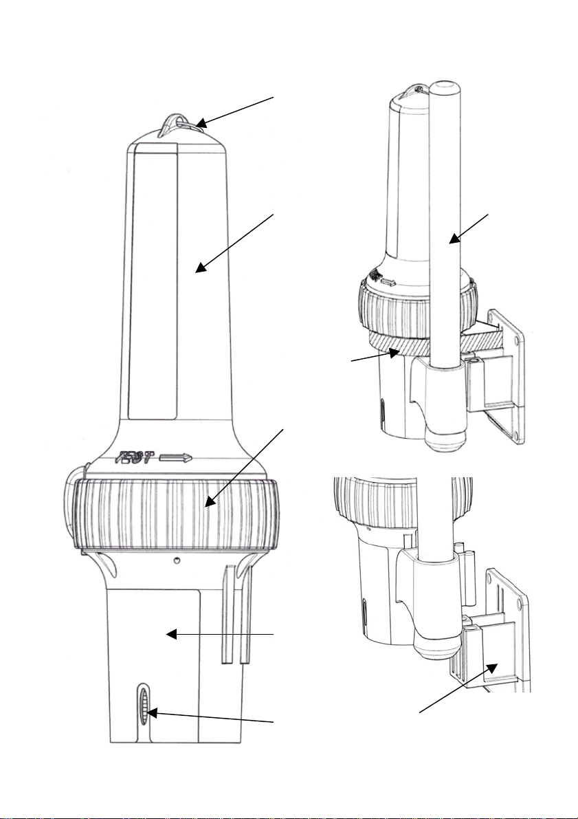
SART General Assembly
Ring for internal
liferaft m oun ti ng
Radome
Velcro strap
Operating
swit ch ring
Mounting
pole
Battery pack
Lanyard
5
Bulkhead
Mounting
bracket
(Velcro strap omitted for clarity)
Page 8
Operating instructions
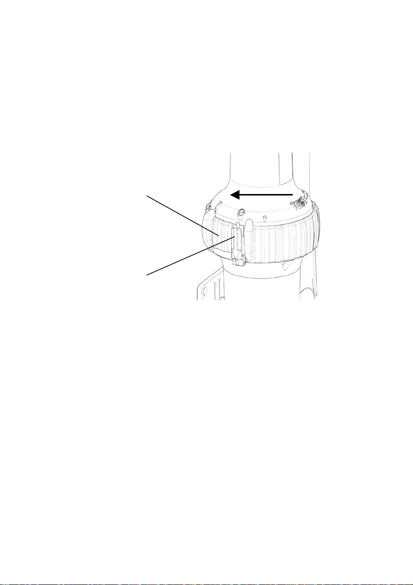
Remove from bulkhead bracke t:
Release Velc ro strap a nd lift SART from bracket
To switch on:
Pull the security tab away from the body of the SART
Rotate the sw itch rin g cloc k wise (ie to the left) to the ON positi o n marke d
by “1”
Switch ring
Security tab
To extend the telescopic pole:
Grasp rubber cover at bottom of pole, and twist the pole to release it in the
pole mount.
Pull the pole down and twist to lock in place in the pol e m ount
Remove rubber cover from bottom of pole ; allow pole sections to drop.
Lock sections together by twisting each sect ion .
To d eplo y i n a sur v ival craft (li feraft) :
Extend the SART supporting pole as detailed above
Tether the SART to a suitable point using the lanyard which unwinds from
its base.
Inset the SART through the port in the canopy
Position the bottom of the support pole in the antenna pocket
Secure the pole to the canopy support.
Some survival craft have the SART already packed as part of the inventory. In
general, these models of SART are not fitted with the support pole. The SART
should be switched ON then suspended by its top loop from the highest point of the
survival craft.
ON
6
Page 9
Self test facility
Regular testing of the SART is advised. The duration of the test should be limited to
as short a time as possible as the SART response may be received by other
vessels which are within range.
There are no operational differences between TEST and ON modes; the rotary
switch must be held in the TEST position, on release it returns to the OFF position.
1. Ensure compliance with all applicable Health and Safety instructions when
working in proximity to a radar transmitter.
2. Locate the SART within the line of sight of an operating approved marine
Radar.
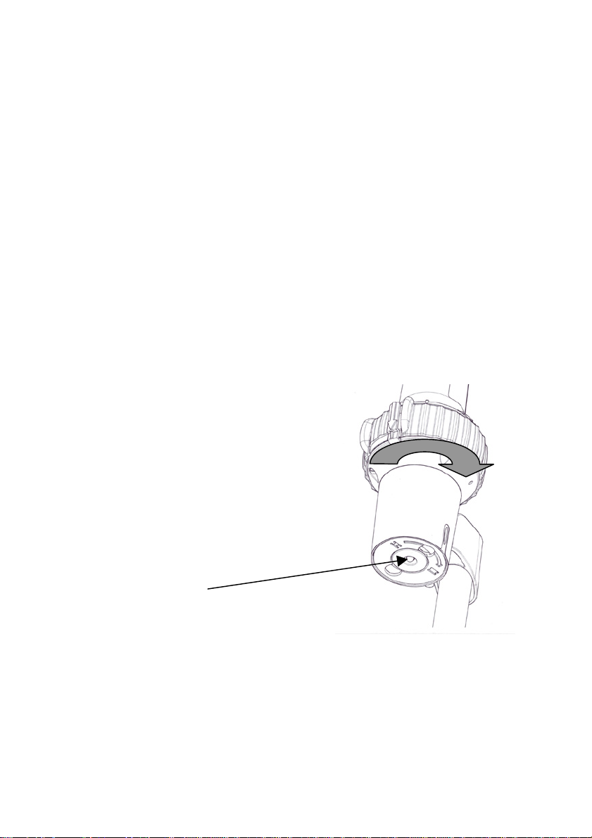
3. Rotate the switch ring anticlockwise (ie to the right) to the TEST position, and
hold it in this position.
a) If the SART responds to the radar, the red light in the base of the SART
will be contin uousl y li t a n d the buzzer will sound every 2 seconds.
b) If the SART does not respond to the radar, the red light will flash every 2
seconds and the buzzer will not sound.
4. Switch off the SART by releasing the switch ring; check that it returns fully to
the OFF position.
TEST
Indicator light
Battery replacement
The battery should be changed 5 years from the date of manufacture shown on the
label and routine test procedures should be carried out.
It is recommended that battery change should only be performed by an authorised
McMurdo service agent, in order that a complete assessment and integrity check
can be performed. The replacement battery kit is McMurdo part number 86-630.
7
Page 10

Technic al description
A single switched antenna is used for both receive and transmit functions; the
switch normally connects the antenna to the receiver circuit. In the standby state
only the receiver portion of the SART is powered to reduce battery consumption to
a mi nimum. In t his condi t ion the indic ator circ uit causes the L ED to flash once
every two seconds.
On r eceipt of a radar pulse th e video amplifier an d detec tor circuit c auses the rest
of the circuitry to become active and the unit switches to transmit mode. In this
condition the indicator circuit causes the LED to remain steady and the buzzer to
sound every two seconds.
The detection of a radar pulse causes the switch to connect the antenna to the
transmitter circuit. The output stage is fed by a Voltage Controlled Oscillator (VCO),
whose frequency is determined by a sweep generator. When triggered by the
detector the sweep generator turns on the VCO and causes it to produce exactly 12
forward and reverse frequency sweeps before shutting down again.
If no radar pulses are detected for a period of 15 seconds the unit reverts to
standby mode.
Functi on ch ar t
SART STATUS BUZZER RED LED
OFF OFF OFF
STANDBY MODE
(TEST or ON)
ACTIVELY
TRANSPONDING
(TEST or ON)
EVERY 2 SECONDS
OFF
ON
8
FLASHING
EVERY 2 SECONDS
ON
Page 11
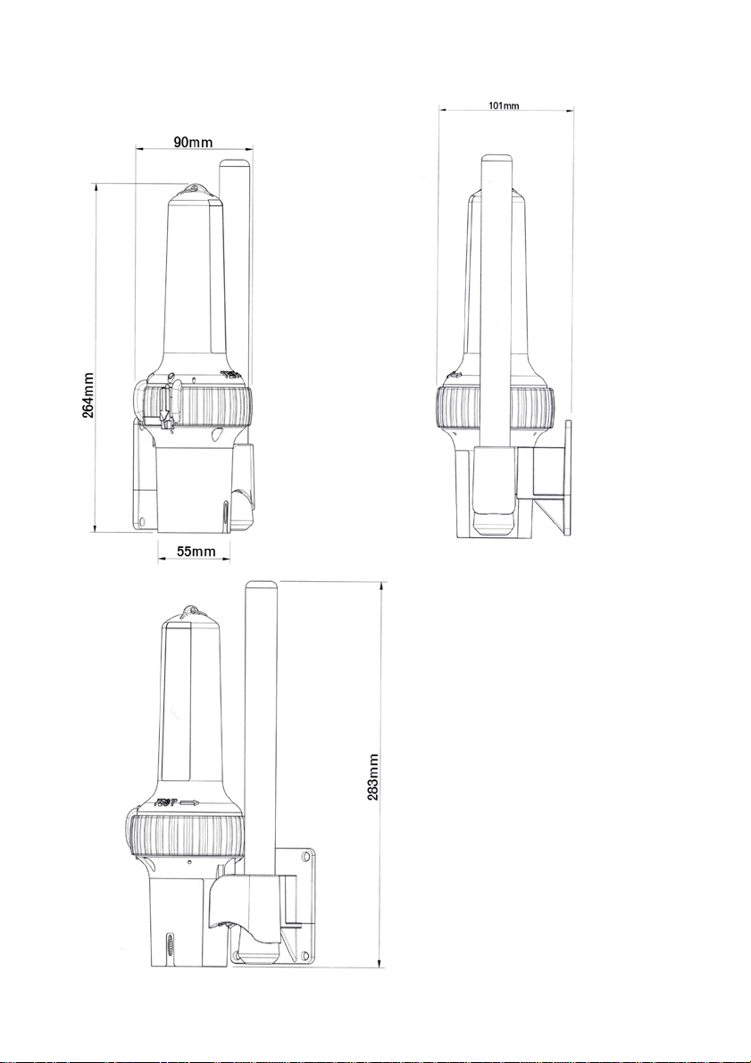
Dimensions
9
Page 12

Operation of marine radar for SART detection
Radar Range Scale
When looking for a SART it is preferable to use a range scale between 6 and 12
nautical miles. This is because the spacing between the SART responses is about
0.6 nautical miles (1125 metres) and it is necessary to see a number of responses
to distinguish the SART from other responses.
SART Range Errors
There are inherent delays in the SART responses; the SART has a trigger delay
and may also have to sweep through the whole radar band before reaching the
frequency of the search radar. At medium ranges of about 6 nautical miles the
range delay may be between about 150 metres and 0.6 nautical miles beyond the
SART position. As the SART is approached the radar delay of the first dot should
be no more than 150 metres beyond the SART position.
Radar Bandwidth
This is normally matched to the radar pulse length and is usually switched with the
range scale and the associated pulse length. Narrow bandwidths of 3.5MHz are
used with long pulses on long range and wide bandwidths of 10-25MHz with short
pulses on short ranges. Any radar bandwidth of less than 5MHz will attenuate the
SART signal slightly so it is preferable to use a medium bandwidth to ensure
optimum detection of the SART. The Radar operating manual should be consulted
about the particular radar parameters and bandwidth selection.
Radar Side Lobes
As the SART is approached side lobes from the antenna may show the SART
responses as a series of arcs or concentric rings. These can be removed by the
use of the anti-clutter sea control although it may be operationally useful to observe
the side lob es as th ese wi ll co nfirm that the S ART is near to the ship.
Detuning the Radar
To increase the visibility of the SART in clutter conditions the radar may be detuned
to reduce the clutter without reducing the SART response. Radar with automatic
frequency control may not permit manual detuning of the equipment. Care should
be taken in operating the radar detuned, as other wanted navigational and anticollision information may be removed. The tuning should be returned to normal
operation as soon as possible.
Gain
For maximum range SART detection the normal maximum gain should be used.
10
Page 13
Anti-Clutter Sea Control
For optimum range SART detection this control should be set to the minimum. Care
should be exercised as targets in sea clutter may be obscured. Some radar sets
have automatic/manual anti-clutter sea control facilities in which case the operator
should switch to manual.
Anti-Clutter Rain Control
This should not be used when trying to detect SARTs as the SART responses may
be removed by this control. Some sets have automatic/manual anti-clutter rain
control facilities in which case the operator should switch to manual.
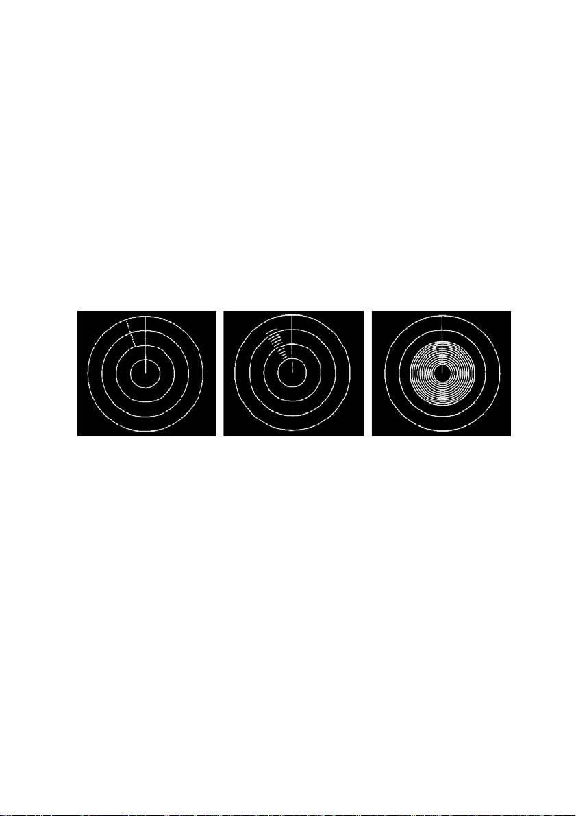
Radar Displays
These sketches show the appearance of a SART response at different ranges.
SART response
from distant
liferaft (5-6 miles)
SART response
from liferaft at
medium range (2-3
miles).
Note widening of
“echos”
11
SART response
close to ve ss el
(<1 mile).
Display now
shows “rings”
caused by
strength of
signal
Page 14

Technical Specification
FREQUENCY: 9.2GHz - 9.5GHz
POLARIZATION: Horizontal
SWEEP RATE:
RESPONSE
SIGNAL:
FORM OF SWEE P:
PULSE EMISSION:
EIRP: >400mW (+26dBm)
RX SENSITIVITY: Better than –50dBm (0.1 mW/m2) (Note 1)
DURATION: 96 hours in standby condition followed by a minimum 8
TEMP RANGE: Operatin g: -200C to +550C
RECOVERY TIME:
ANTENNA HEIGHT: Greater or equal to 1m (Note 2)
RESPONSE DELAY:
ANTENNA BEAM: Vertical: +/-12.5 degrees
WEIGHT: SART only: 360g
DIMENSIONS: Overall, in bracket: 283 x 101 x 90mm
BUOYANCY: Buoyant
5µs per 200MHz nominal
12 sweeps
Forward: 7.5µs ± 1µs
Reverse: 0.4µs ± 0.1µs
100µs nominal
hours of transmission while being continuously
interrogated with a pulse repetition frequency of 1kHz.
Storage: -300C to +650C
Following excitation: 10µs or less
0.5µs or less
Azimuth: Omnidirectional t o +/-2dB
SART + pole: 510g
SART complete: 530g
Note
1. Effective receiver sensitivity includes antenna gain.
2. The effective antenna height applies to equipment required to meet
Regulation 6.2.2 of Chapter III and 7.1.3 and 8.3.1 of Chapter IV of
the 1988 Amendments to the 1974 SOLAS Convention.
Standards
Compli es with IMO Reso lution A.802( 1 9)
Test and Approval Standards are specified on the Declaration of Conformity
following.
12
Page 15
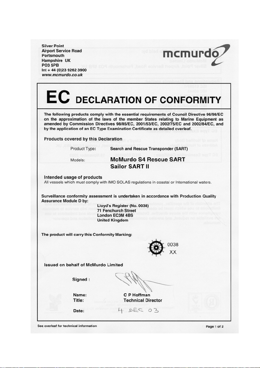
Declaration of Conformity
13
Page 16
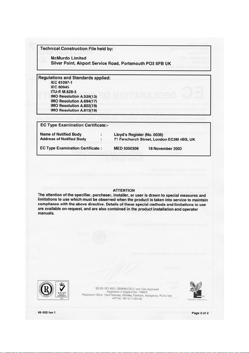
Declaration of Conformity (page 2)
14
Page 17

Limited Product Warranty
Subject to the provis i ons s et out bel ow Mc M ur d o Li mi ted warr ants that this pr oduc t w il l be f r ee
of defects in m aterials and workmans hip for a period of 12 m ont hs from the dat e of pur c h as e.
McMurd o Li mited will n ot b e liab l e t o the bu yer under the above w arr an ty:-
• for any defect arisi ng from fair wear and t ear , w ilf ul dam age, neg li g ence, abnor m al
working conditions, failure to follow McMurdo Limited's instructions (whether oral or in
writing) inc luding a f ailu r e t o inst al l pr op er ly and/or t o us e batteries recomm end ed and /or
suppli ed b y Mc M urd o Limited , mis use or alterations or r ep air of th e pr od uc t b y per sons
other th an McMurd o Lim ited or an Approved S ervice Agent;
• for parts , m at eri als or eq ui pm ent not man ufactur ed by Mc M urdo Limit ed in respect of
which the buyer sh all on l y be en titled to th e benefit of an y w arranty or gu arantee gi ven
by the manufacturer to McMurdo Limited;
• for the battery storage life which is specifically excluded from this warranty;
• if the total pr ice for the pr oduc t h as n ot been paid.
McMurd o Li mited does n ot m ak e any other promises or war r anties (exp ress, imp li ed or
statut or y) ab out the prod uc t except where the produc t is s old t o a c ons u m er in wh ic h c as e the
statut or y rights of a c ons um er are not to be affected.
In order to b e val id, claims m ust be made u nd er the above w arranty in wr iting as soon as
practic able after dis covery of th e d efect or failure and wit h in th e w arr an ty peri od referred t o
above. Proof of purchase will be required. The claim should be sent together with the product
in questi on t o the address s et out b el ow or t o an Approved S er vice Agent.
Follow in g a val id warran t y cl aim Mc Mu r d o Li mited sh all b e enti t l ed t o rep ai r or r epl ace the
product (or part) in qu es ti on free of ch ar g e, or at Mc M urdo Limit ed 's sol e dis c retion to ref u n d
to the buyer t h e price of the pr oduc t (or a propor ti onal part of the price). Mc Murdo Li mit ed
shall not b e li abl e t o a bu yer w h o is n ot a cons u m er f or an y oth er l oss or dam ag e (whet h er
indirect , sp ec i al or c onsequential loss of profit or ot h erwise) c osts , expenses or oth er cl ai ms
for comp ensation w hic h arise out of or in c onn ect i on w ith th is prod uc t. In th e c as e of a
consumer McMurdo Limited shall only be liable where other loss or damage is foreseeable.
Nothing sh all limit McMurd o Lim it ed's liability for death or person al in jur y c aused by its
negligence.
This warranty is to be interpreted under English law.
All enquiries relating to this warranty or Approved Service Agents should be sent to:
McMurdo Limited
Silver Point, Airport Service Road, Portsmouth, Hampshire, PO3 5PB UK
Telephone: Int + 44 (0) 23 9262 3900 Fax: Int + 44 (0) 23 9262 3998
Web: www.mcmurdo.co.uk Email: [email protected]
15
Page 18

User Note s17This page contains no other data
16
Page 19

Page 20

McMurdo Ltd
Silver Point
Airport Service Road
Portsmouth
Hampshire
United Kingdom
PO3 5PB
Telephone: Int +44 (0)23 9262 3900
Fax: Int +44 (0)23 9262 3998
[email protected]
www.mcmurdo.co.uk
A member of Chemring Group PLC
86-920-001 Issue 1
18
 Loading...