

Page 1
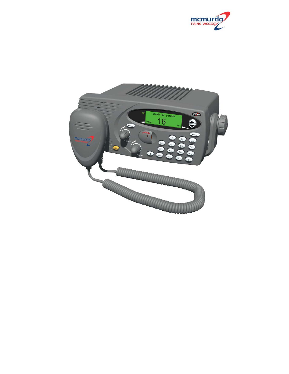
McMurdo F1 DSC
Marine VHF Radio with DSC
Operation Manual
Page 2
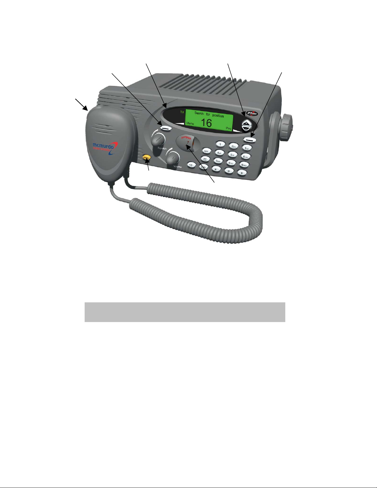
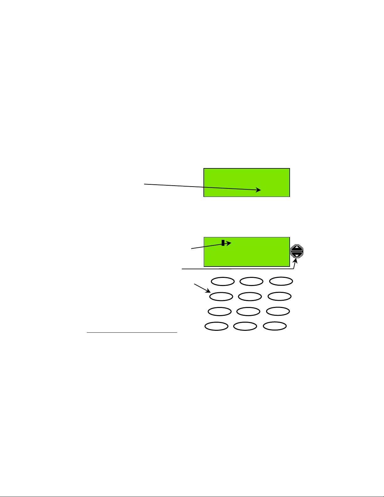
Controls
PTT switch
Left action key
Indicators Scroll keys
Right action key
Power switch
Distress cover
Disclaimer
Information contained in this manual is supplied in good faith, but is liable to change
without notice. McMurdo Limited disclaims any liability for consequences arising
from omissions or inaccuracies in the manuals and documentation provided with
this product.
IMPORTANT: Before you use this transceiver, read and understand all
the instructions in this manual.
2002 McMurdo Ltd.
Page 3
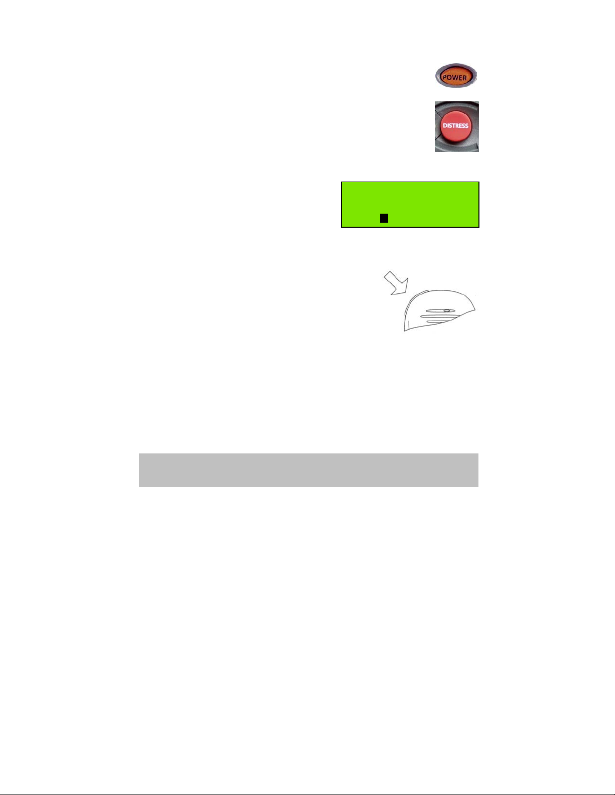
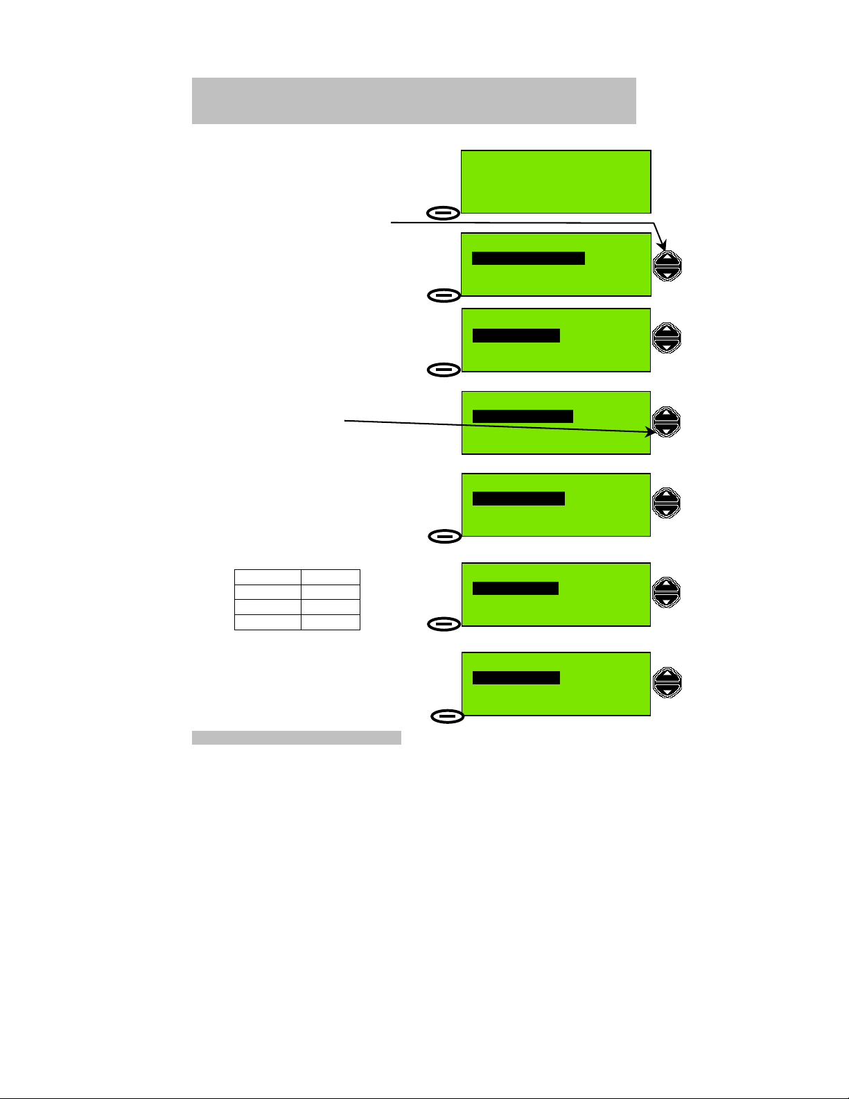
Rapid Distress Call
1. Turn the radio ON (press POWER)
2. Open the cover over the DISTRESS button and press the
button. If the button is pressed for 5 seconds an ‘undesignated’
distress call will be made. If the button is released before 5
seconds, you can select the type of emergency.
If the position information is too old to be valid, you will be
prompted to update it. (See Page 6 for full details.)
3. If there is insufficient time to enter position
information keep pressing the Distress
Button. Do not release the button until
you see this screen.
Distress Call
Undesignated
Wait for Acknowledge
Reset
16
4. Wait approximately 15 seconds for an acknowledgement.
5. When the acknowledgement is received, the radio switches automatically to
Channel 16.
Pick up the microphone, press the PTT (TALK) button
and call for help:
‘MAYDAY, MAYDAY, MAYDAY
This is Ship name, Ship name, Ship name
MAYDAY
This is Ship name, Callsign.
Position:……………………………….
Nature of distress:…….……………..
Help needed:………………………….
(any other information)
OVER’
IMPORTANT: Do NOT make a distress call unless there is grave and
imminent danger. It is an offence to make any unjustified distress call.
Page 4

Introduction
Thank you for choosing McMurdo for your VHF communication requirements.
McMurdo has supplied the maritime market for many years with communication
products of high quality and excellent design, and considers it of utmost importance
that all products are safe and easy to operate.
The product
The McMurdo F1 DSC VHF radiotelephone is designed to meet the high quality
standard required for a product that plays an important role in the safety of the ship
and its crew. The F1 DSC VHF radiotelephone is easy to operate and gives the
user high quality effective radio communication to other ships as well as to shore
based stations. Installation and maintenance is made very simple and can be
carried out by untrained personnel.
A CD-ROM simulating the operation of the F1 DSC radiotelephone can be obtained
from McMurdo on application. This, when installed on a PC-compatible computer,
simulates the operation of the F1 radio together with a simulation of a second
station for exchange of DSC messages.
VHF DSC Radios
VHF radios communicate on fixed frequency bands called channels. There are 57
public channels, numbered 1 to 28 and 60 to 88. (The system is different in US
waters; setting the radio to US changes to that system.)
Some channels are reserved for particular functions:
Channel 16 is reserved for verbal distress calls and for ‘All Stations’ calls.
This channel must NOT be used for other purposes.
Channel 70 is a channel reserved for digital data (DSC).
DSC (Digital Selective Calling) is a digital function which permits a caller to alert a
particular DSC radio (or group of radios) that a standard radio communication is
requested on a specific channel. In this respect, it is similar to a standard telephone
call in that a specific number can be called; however, once the call is accepted,
communication uses normal radio procedures.
DSC also permits automatic distress call alerting; where the appropriate information
is available from external equipment, the alert includes the vessel’s MMSI number,
its position and the exact time of the distress alert. (The distress call is still made
using conventional radio procedures; the DSC function only alerts other radio users
to the intended call.)
Page 5

Verbal Communication
Verbal communication is of two types: simplex and duplex.
• Simplex communication uses a single frequency, so only one transmitter can
be operating at any time. This means that each party in the conversation must
say ‘over’ when stopping transmitting so that the other party knows it is their
turn to transmit. All ship-to-ship communication is in simplex mode. The F1
DSC radiotelephone supports simplex communication.
• Duplex communication uses two frequencies, so both parties can talk at the
same time. The F1 DSC radiotelephone does not support full duplex operation.
• There is also a hybrid mode: semi-duplex. In this mode, one of the
communicating parties operates in duplex mode and the other in simplex. A
good example is ship to coast station communications. The F1 DSC
radiotelephone supports semi-duplex communication.
DSC Digital Communication
DSC (Digital Selective Calling) is a system for establishing communication to a
specified address, to a ‘group’ (a pre-defined set of addresses), or to ‘all parties’ for
a digital distress call.
The key feature of the DSC system is the use of the vessel’s MMSI (Maritime
Mobile Station Identity) number to identify each vessel. (This number is treated as
the vessel’s DSC telephone number.) Consequently, before a DSC call can be
made, the originating vessel’s MMSI must be programmed into its radio and the
receiving vessel’s MMSI must be known to the caller.
All DSC communication is on Channel 70. The radio maintains a continuous watch
on this channel for incoming messages, which are immediately reported. This
monitoring also allows the system to transmit only when the channel is free.
The radio responds to three types of DSC message:
All ships calls. These calls are received by all vessels within range of the
transmitter.
Individual calls. These calls are addressed specifically to the radio MMSI
number.
Group calls. When the radio has been set up as a member of a group, it
responds to calls addressed to the group number.
Page 6
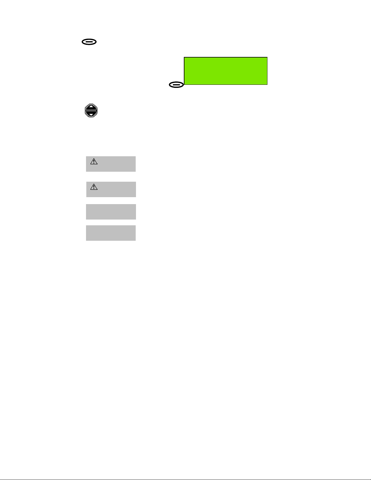
Key to Symbols:
Indicates that an Action key must be pressed.
Example: Press the Menu Action Key.
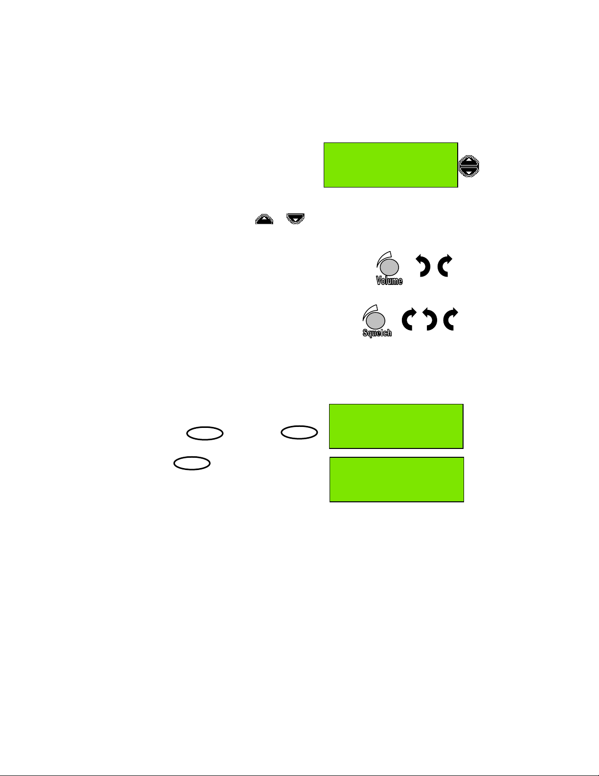
Indicates that the Scroll keys must be pressed to change data
highlighted (displayed in inverse contrast characters) in a screen
or menu, or to change channel in standby mode.
Shaded text
WARNING
CAUTION
IMPORTANT
NOTE
Indicates that the appropriate Action key must be pressed
after data entry / selection is complete.
Instruction to take particular care when performing an action
that may have serious consequences, such as personal
injury, electric shock or fire hazard.
Advice or information to prevent equipment damage .
Highly relevant information. Possible safety implications
(example: position information could be omitted from a DSC
Distress transmission if instruction disregarded).
Inconvenience may occur if advice disregarded.
50°56'N at:08:40
001°34'E UTC
Menu
16 Pos
In the following text ‘radio’ and ‘transceiver’
all refer to the ‘F1 DSC Radiotelephone’.
Page 7

Installing and Using the Transceiver Safely
Installation (see also the F1 DSC radiotelephone Installation Manual)
WARNING: Do not connect the transceiver to a mains (line) AC electrical supply, as an
electric shock or fire hazard could result.
CAUTION: Do not connect the transceiver to a DC supply exceeding 16V or reverse the
supply polarity. Damage to the transceiver can result.
CAUTION: Do not bypass the power cable inline fuse (such as cutting the cable shorter).
CAUTION: The transceiver is designed for operation in the temperature range –15°C to
+55°C. Do not install (or use) the transceiver in areas which exceed this range.
CAUTION: The transceiver is water resistant to international standards. However, if either
the transceiver or microphone casing is damaged (e.g. due to heavy impact) then the sealing
cannot be guaranteed.
WARNING: Do not install the transceiver in a position where;
a) the controls of your vessel may be obstructed.
b) it may obstruct your normal movement around your vessel.
c) it may cause bodily injury.
d) it cannot be easily accessed in an emergency.
Use
WARNING: Certain parts of the chassis can become hot during extended periods of
operation, notably the rear panel (connectors and radiator fins). Avoid touching these areas
when the radio is operating.
WARNING: Do not touch the rear connections, notably the antenna connector, when the
transceiver is operating and do not touch the antenna whip (mast) or connecting cable when
operating the transceiver, for RF exposure and electrical safety reasons. Refer to Radio
Frequency Exposure Warning.
WARNING: Opening the transceiver cover will invalidate the warranty. Do not open the
cover when the transceiver is operating, or connected to a power supply.
Maintenance
CAUTION: Avoid using chemical solvents to clean the transceiver as some solvents can
damage the case material.
NOTE: The transceiver contains no user serviceable parts. Return to your Service Agent for
repair.
Page 8

Radio Frequency Exposure Warning
To meet the current requirements for Radio Frequency Exposure it is necessary to
install the antenna mast correctly and operate the equipment according to the
instructions.
WARNING: The antenna mast must be mounted at a minimum distance
(vertical separation) of 3 metres from the head of any person to meet
international safety directives on Maximum Permissible Exposure (MPE) /
Specific Absorption Rate (SAR).
The assumptions used in this assessment are: full transmit power and a good
antenna are used (assumed to be a 9dBi gain omnidirectional type).
Where no suitable structure exists to achieve a 3 metre vertical separation then the
antenna base must be mounted at least 1 metre above the head of any person
within range and all persons must stay outside the 3 metre safety radius.
WARNING: Do not transmit when persons are closer than 3 metres to the
antenna. If any person (e.g. the operator) must be closer, then a grounded RF
shield should be interposed between that person and the antenna.
Failure to adhere to these limits could expose persons within the 3 metre radius to
RF radiation in excess of the MPE / SAR limits.
Rules of Operation
Licensing
IMPORTANT: In most countries the operator of the transceiver must possess a
current radio telephone licence, and the equipment must be registered (Call
Sign and MMSI number). Please contact the relevant authority in your country
for more information.
IMPORTANT: Normal users of the transceiver should be trained, licensed
operators, but this rule is waived in an emergency and any person can transmit
a Distress Call.
General radio operating procedures
Monitor Channel 16 when not using a different channel. The transceiver is
designed to revert to this channel.
False alarms cost lives and money. Do not make unjustified Distress Calls.
Information you overhear, but not intended for you, must remain private and should
not be used or repeated.
Do not use profane or indecent language.
Page 9

Contents
Controls and Indicators...................................................................................... 1
Power ................................................................................................................1
Volume ..............................................................................................................1
Squelch.............................................................................................................. 1
Distress.............................................................................................................. 2
16....................................................................................................................... 2
1/25.................................................................................................................... 2
dual watch .........................................................................................................2
light .................................................................................................................... 2
Scroll keys ......................................................................................................... 2
Action keys ........................................................................................................ 3
PTT key ............................................................................................................. 3
Indicators............................................................................................................. 3
US...................................................................................................................... 3
TX...................................................................................................................... 3
1W ..................................................................................................................... 3
Display............................................................................................................... 4
Basic Telephony Operations.............................................................................. 6
Power On/Off..................................................................................................... 6
Entering Time, Date and Position ...................................................................... 6
Receiving and Transmitting ...............................................................................8
Private Channels ...............................................................................................8
Receiving Telephony (Voice) Calls.................................................................... 9
Setting Channel Numbers.................................................................................. 9
Making Telephony (Voice) Calls ...................................................................... 10
Returning to Channel 16.................................................................................. 10
Speaker Mute Function.................................................................................... 11
Display and Keyboard Dimming.......................................................................12
Auto Dim.......................................................................................................... 12
Basic DSC Operations ...................................................................................... 13
Receiving an Individual DSC Call .................................................................... 13
Transmitting a DSC Call to a Ship Station ....................................................... 14
Transmitting an Individual DSC Call Using Called Station Name ....................15
Transmitting a Call to a Coast (Shore) Station ................................................ 16
Transmitting a Call to a Group......................................................................... 18
Full Telephony Operations............................................................................... 19
Changing the Priority Channel......................................................................... 19
Dual watch....................................................................................................... 20
Channel scanning............................................................................................ 21
Scan program .................................................................................................. 21
Incoming DSC Call During Scanning and Dual Watch..................................... 21
Scanning All Channels..................................................................................... 22
Inhibiting a Channel......................................................................................... 23
Creating and Editing a Scan Program .............................................................24
DISTRESS .......................................................................................................... 26
Rapid Distress Call............................................................................................26
Page 10

Full DSC operations.......................................................................................... 27
Distress Call Including Nature of Distress........................................................ 27
Transmitting an All Ships Call .......................................................................... 31
Received message log......................................................................................33
Directory ............................................................................................................35
Adding a Directory Entry.................................................................................. 35
Erasing a Directory Entry................................................................................. 36
Search for a Directory Entry ............................................................................36
Individual or Group Calls Using the Directory................................................ 36
Setting Profiles..................................................................................................37
Setting the MMSI Number ...............................................................................37
Group MMSI Numbers..................................................................................... 38
Scan Dwell Time.............................................................................................. 38
Key Beep ......................................................................................................... 39
Channel Mode .................................................................................................39
Speaker Settings .............................................................................................40
Notify Beep Volume ......................................................................................... 40
Auto Dim.......................................................................................................... 41
Software Version .............................................................................................42
Position Indication............................................................................................ 42
Time/Date and Offset....................................................................................... 43
Radio Test ....................................................................................................... 44
APPENDICES.......................................................................................................1
Appendix A: Character Entry .............................................................................1
Appendix B: Menu Hierarchy ............................................................................. 2
Appendix C: Error messages / Troubleshooting.............................................. 4
Appendix D: Channel Specifications................................................................. 9
International....................................................................................................... 9
US Channels ................................................................................................... 10
BI Channels .................................................................................................... 11
OTHER INFORMATION .......................................................................................1
Line of Sight distances....................................................................................... 1
McMurdo Limited Product Warranty..................................................................2
Declaration of Conformity .................................................................................. 3
Page 11
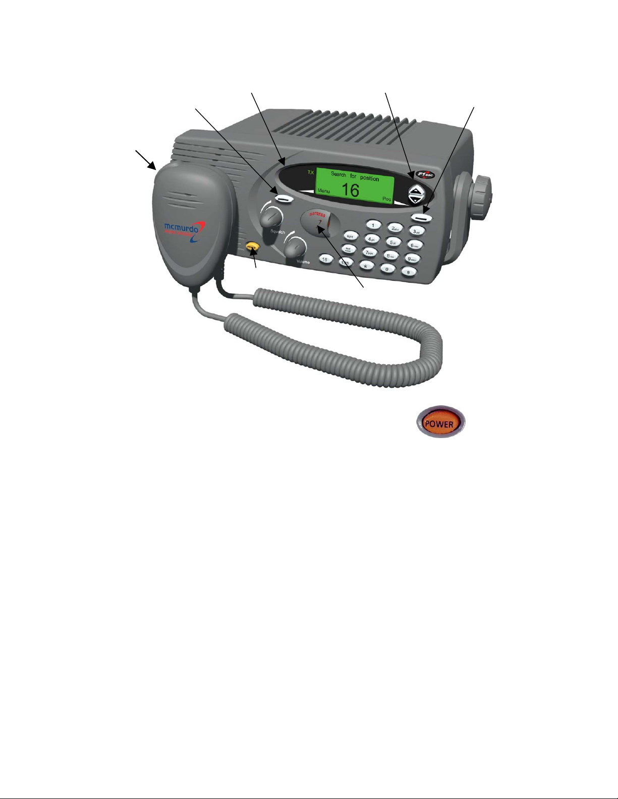
Controls and Indicators
PTT switch
Indicators
Left action key Right action key
Power switch
Scroll keys
Distress cover
Power
The Power button is an ON/OFF switch. Because it is separate
from the volume control, there is normally no need to reset the
volume level after switching ON the radio. To switch on the radio
press Power, briefly, until display becomes active.
Volume
The Volume knob is a standard rotary control. It controls the volume of both the
internal and external speakers.
Squelch
The Squelch knob sets the level at which signals become audible. It is used to
suppress the background noise, and should be set at the point where the noise is
just inaudible. Setting Squelch at too high a level may suppress weak signals.
Page 1
Page 12
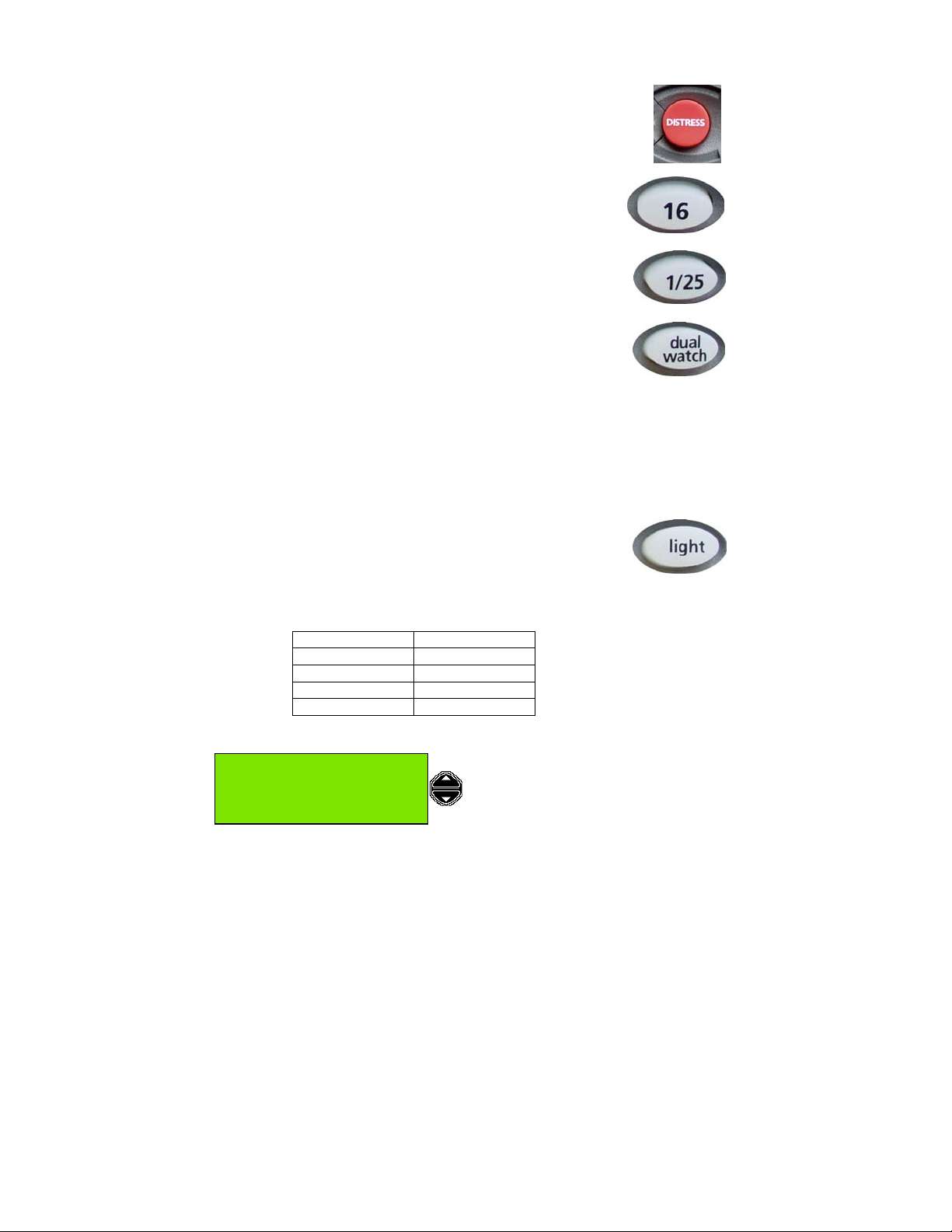
Distress
This control is a button which is concealed by a sprung cover, so
preventing accidental activation of the DSC automatic distress alert
operation.
16
This button immediately switches the radio to a listening watch
on Channel 16. This function takes priority over any activity
other than a distress call.
1/25
This button toggles the output power of the radio between 1W
and 25W on successive operations.
dual watch
This button allows the radio to monitor both the selected channel
and Channel 16 automatically.
To use the Dual Watch function, first set the radio to the desired
channel, then push the dual watch button. The display will alternately display the
selected channel number and channel 16, at a rate which is controlled by the scan
dwell time (refer to the 'Setting Profiles' section for information on this parameter).
Pressing the dual watch button again cancels the dual watch and returns the radio
to a listening watch on the selected channel.
light
This button controls the backlighting of the display and
keyboard.
When the button is first pushed, it sets the keyboard backlight
ON and the display backlight DIM. Successive pushes of the button cycle the
lighting though the sequence:
Display Keyboard
DIM ON
FULL ON
OFF OFF
DIM (reversed) ON
Scroll keys
50°56'N at:08:40
001°34'E UTC
Menu
Page 2
11 Pos
The Scroll Keys are the two buttons on
the right of the display. Scrolling is used
to cycle through available choices, to
move the display list up and down and to
set the channel. Scroll also allows DSC
messages to be read in their entirety.
Page 13

Action keys
The Action Keys are the two keys
indicated by pointers below the
display. Their function changes
according to the
operational mode of the
radio, and is shown by appropriate labels on the display.
In ‘normal’ mode (‘standby screen’), the Left Action key and Right Action key
have the functions Menu and Pos, respectively.
Menu displays the parameters for digital control of the radio; the scroll keys move
through the menu or sub-menu items.
Pos displays the positional data (if any) last acquired by the radio, either from
numeric entry or from the electronic NMEA interface, and allows these data to be
changed manually.
PTT key
(PTT switch). Press-to-Talk key.
Press and hold the PTT key to make a voice (telephony) call.
Release the PTT key when you stop talking.
50°56'N at:08:40
001°34'E UTC
Menu
11 Pos
Indicators
US
This indicator lights to show that the radio is operating with the US specification of
VHF channels. This setting is selected using the Profiles menu.
TX
This indicator lights when the radio is transmitting.
1W
This indicator lights when the radio is operating in its low power (1W) mode.
Page 3
Page 14
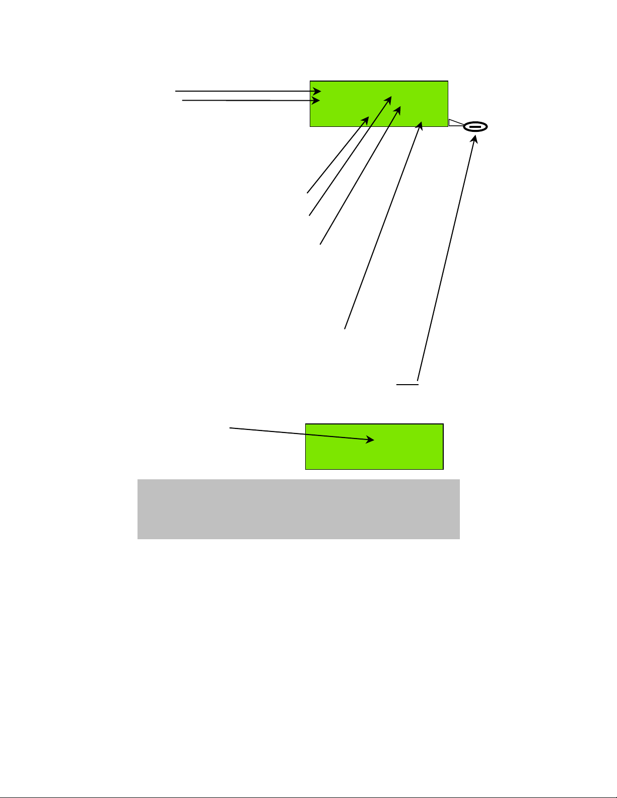
Display
The ‘standby screen’ is shown here.
This is the display for normal radio operation.
Latitude
Longitude
are shown here as 'standard' position
values. If ‘enhanced’ position is selected
(see page 42 'Setting Profiles:
Position Indication')
then position is shown to the
nearest second ("). Example: 50°56'23" N.
F1 radio is currently tuned to Channel 11.
‘at: HH:MM’ displays the vessel local time
in 24 hour format.
50°56'N at:08:40
001°34'E
Menu 11 Pos
/
/ indicates that 1 or more DSC message(s)
has/have been received and not yet read.
Alternatively, with no unread messages,
this area of the screen may display the text
‘Off:+01:00’ (for example) if the local time is
offset from UTC (Co-ordinated Universal Time),
or simply UTC if local time and UTC are identical.
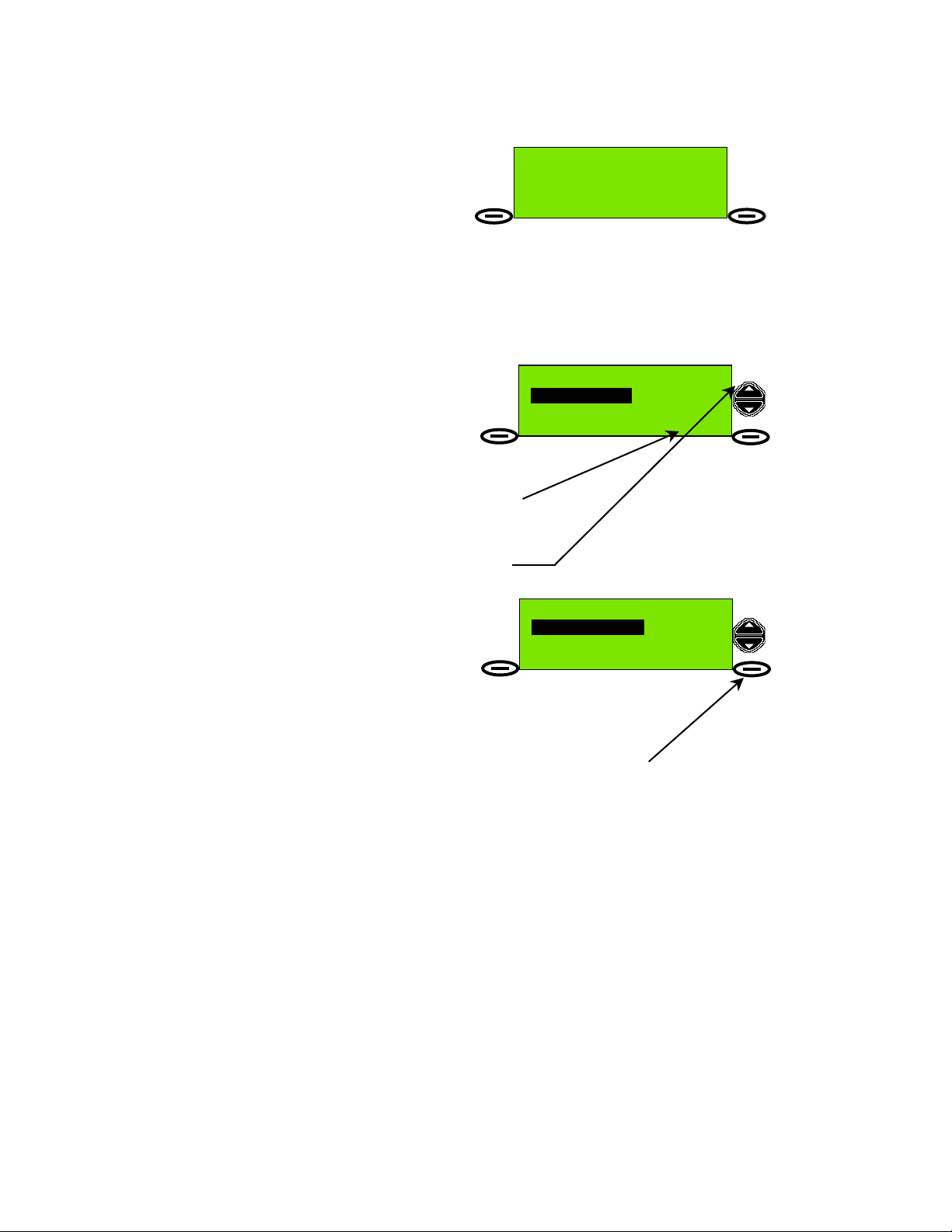
Menu and Pos are indications of Action key function.
In the standby screen, the left action key function indicator
is associated with the button to the lower left corner of the display,
and the right action key function indicator with the lower right button
(see example above) so if the user pushes the button labelled
Pos the display will change to the Position screen, and the Pos
key will have a different function, it will become the Exit
key.
Standby screen showing offset time
value Off:+hh:mm.
Where no offset exists the
text UTC is displayed.
In either case no unread messages
exist, or else the text is replaced by
NOTE: if the ‘Auto Dim’ feature (see 'Display and Keyboard Dimming : Auto
Dim') is enabled, the display will dim after 5 minutes of keypad inactivity. Any
single key press in the auto-dimmed state will brighten the display, (but not
perform other any action) so an additional key press is required to initiate the
desired action.
Page 4
50°56'N at:08:40
001°34'E Off:+01:00
Menu
/.
11 Pos
Page 15
How to Access F1 Radio Features Using the Menu
The F1 radio is easy to operate. Many functions are available from simple front
panel controls, but most features are accessible from the easy to navigate ‘menu’
(series of linked software controls).
The main menu is accessible from standby
mode. The standby display (or ‘screen’) is
shown here.
The Menu action key (associated with the
Menu label on the standby screen) must be pressed to
allow access to menus. The menu comprises
nested levels of screens providing options to select
or setup various features of the radio.
As the menus are navigated the action key labels
change, dependent on the options available at each
level of menu.
At its most basic, navigation of menus
requires selection of menu mode or level
(normally left Action key), examination of
available options (via the Scroll keys),
followed by selection of the desired
option (left Action key again).
Once the desired option has been selected, or the
user decides not to effect a change, then the
right Action key (normally labelled Back or Exit)
is pressed to return to previous menu levels, and
ultimately to the standby screen.
This example shows the effect of pressing Menu,
followed by a single press of the Scroll Up key.
Subsequently, pressing the Left Action key
(now labelled Select) will allow the user to
access a menu sub-level called Profiles (radio
settings), and the first sub-menu option is
Scan dwell time.
50°56'N at:08:40
001°34'E UTC
Menu
Profiles
Profiles
Scan dwell time
Select Back
16 Pos
If you want to change Scan Dwell Time press
the Select
scroll keys to list other menu options, then press
Select to change the desired option settings.
If you do not want to change anything at this menu level, press the Back key
(Right Action key).
The menu hierarchy (or structure) is described in more detail in ‘Appendix B:
Menu Hierarchy’ section of this manual.
action key, otherwise use the
Page 5
Page 16
Basic Telephony Operations
v
Power On/Off
The F1 radio is switched ON and OFF by the POWER button (see page 1).
When the radio is switched ON, it performs a series of self-tests including memory
and key and display illumination tests. When complete the display shows radio
identity and type information, then switches automatically to a listening watch on
Channel 16.
If any problem is encountered, a message is displayed. These messages and the
appropriate corrective actions are discussed in ‘Appendix C: Error Messages /
Troubleshooting’.
1
Note that the radio automatically looks for a GPS
radio NMEA
2
interface) to provide positional information and time and date. During
the check for a GPS source the display reads Search for position. If GPS is not
available after 2 minutes, the message Pos update not found is displayed for 2
seconds and the missing position, time and date information is represented on the
display by blanks (−−). The screen now appears as follows:
signal source (connected to the
Time / date and position information can
now be entered manually, using the
Update Action-key.
Note: until the user enters time / date and
position information, the radio will emit a
beep every minute as a warning that
important safety data will not automatically
be sent with DSC messages.
Entering Time, Date and Position
Press the Update key. This screen is
now displayed. A cursor (text entry point)
appears (flashing) above the first latitude
character entry point. To move the cursor
to the right press the lower scroll key.
To move left press the upper scroll key.
To enter digits press the numeric keys
0-9.
The cursor moves right one digit for each
digit entered, until the end of the line is
reached. The last character (N or S for
latitude, or E or W for longitude is set by
pressing any key from
0-9, * or #. Each
press changes to E/W or N/S.
1
GPS = Global Positioning System
2
NMEA = National Marine Electronics Association
Page 6
−−°−−'− at:−−:−−
−−°−−'− UTC
Menu
Lat: −−°−−'−
Long: −−°−−'−
Pos at:−−:−− UTC
Done Back
11 Update
4ghi 5jkl
7pqrs
*
0
2abc
8tu
3def
6mno
9wxyz
#
Page 17

To move to another line press a scroll key. Time (hh:mm) must now be entered in
the Pos at:−−:−− blank area. If time is not entered (and the Done Action-key is
pressed) the message Invalid Time will appear for 2 seconds. Note that entering a
time via the Position Update screen will not update the radio clock time
static time, which should be updated every 4 hours as a minimum, where no GPS
data source is available. Clock time (and date) is set in ‘Profiles’
3
. It is a
4
(accessible via the Menu Action key).
3
The radio internal clock operates only when power is available to the radio, and must be manually set, or the clock sets
itself using a GPS data source.
4
Please refer to the 'Setting Profiles' section of this manual for details on setting clock time.
Page 7
Page 18
Receiving and Transmitting
The radio will operate as a basic transceiver for verbal communication without
requiring any information programmed into it.
However, it cannot be used as a DSC communication system before it has a 'profile'
set into it (i.e. as a minimum, the MMSI number must be set).
Please refer to the 'Setting Profiles' section 'Setting the MMSI' for more information.
Listening for Voice Communications (Telephony Calls)
To prepare to listen to telephony calls:
1. Ensure the radio is in the standby state
(standby screen is shown here) using the
action keys if necessary.
2. Set the radio to an appropriate channel. This is normally channel 16 (the radio is
designed to monitor channel 16 by default). If a different listening channel is
required press the scroll keys:
number, or use the numeric keys to set the channel directly. See also ‘Private
Channels’.
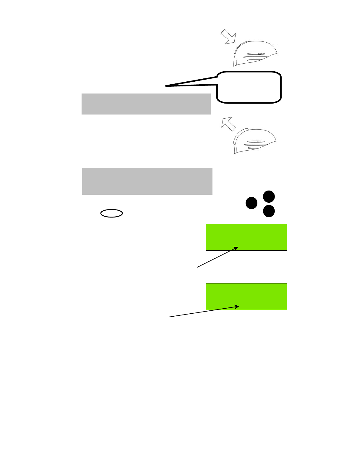
3. Set volume control to a comfortable level. A suitable
starting level is with the volume control rotated fully anti(counter) clockwise and then rotated a few degrees
clockwise.
4. (a) Rotate the squelch control fully clockwise to
‘squelch’ the channel, (b) then rotate slowly anticlockwise until noise is heard on the free channel,
(c) then rotate slightly clockwise to squelch the channel
again.
or to increase or decrease the channel
50°56'N at:08:40
001°34'E UTC
Menu
16 Pos
a b c
5. Readjust the volume control if necessary. If sound cannot be heard, check that
the internal speaker is enabled (go to Profiles->Speaker settings).
Private Channels
To select a Private Channel (example P1, M2):
1. Press the
key (for P).
2. Press
3. You have now selected Private Channel P2.
Subject to certain restrictions, your Service Agent can set up your Private Channels.
[See also ‘Setting Channel Numbers’ on page 9.]
Page 8
2abc
key then the
7pqrs
50°56'N at:08:40
001°34'E UTC
Menu
50°56'N at:08:40
001°34'E UTC
Menu
P Pos
P2 Pos
Page 19
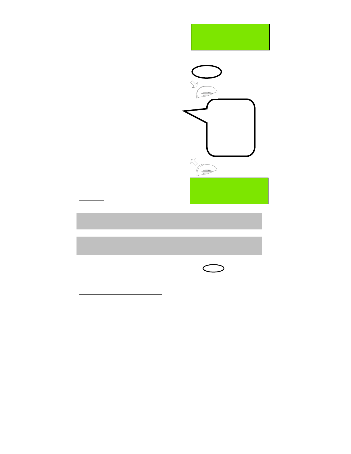
Receiving Telephony (Voice) Calls
When a call is received and the call sign of
your vessel (or station name) is heard in
loudspeaker (or handset where appropriate):
1. Pick-up the fist-microphone or handset and
press and hold the PTT key, to answer the call.
Press / hold
PTT key
2. Say:
‘<CALLING STATION NAME>
This is <YOUR STATION NAME>’.
NOTE: It is essential to propose a working channel for
subsequent communications
(not Channel16).
3. Say: ‘Over’
then release the PTT key and wait for an
acknowledgement from the caller, which should
include the new working channel (if suggested).
4. Set the radio to the working channel (please refer
to the Setting Channel Numbers section) before
resuming communication.
NOTE: Press the PTT key only when talking.
If a simplex channel is used (refer to Appendix D:
Channel Specifications) it is necessary to say ‘Over’
when you stop talking.
For normal communications, very near to coasts,
in ports and marinas, use the 1W power setting.
(Press the key until the 1W LED is lit.)
1/25
Setting Channel Numbers
The active channel is changed using the scroll
keys or by entering the channel number from the
keyboard, when in standby mode.
SeaMist.
This is SunCruiser.
(Goto) Channel 68.
Over.
Release PTT key
US
50°56'N at:08:40
001°34'E UTC
Menu
2 Pos
TX
1W
To change a channel using the keyboard press
a numeric key (example ‘2’). The existing channel
setting clears and ‘2’ appears channel indication
section of the display.
If no other numeric key is pressed within 2
seconds then the F1 radio is set to channel 2.
If another numeric key is pressed (example ‘3’)
then the displayed digit ‘2’ moves left by 1 digit
position and ‘3’ becomes the channel units digit.
The radio is now set to channel 23.
[See also ‘Private Channels’ on page 8.]
50°56'N at:08:41
001°34'E UTC
Menu
23 Pos
Page 9
Page 20
Making Telephony (Voice) Calls
To initiate a radio telephone (telephony) call:
1. Ensure the radio is in standby mode and
select a channel
(channel 16
5
or another suitable channel).
50°56'N at:08:41
001°34'E UTC
Menu
16 Pos
2. Select transmit power:
1W for short range, or 25W.
3. Pick-up the fist-microphone or handset and
press and hold the PTT
6
key.
4. Say:
‘<CALLING STATION NAME>’ (3 times)
‘This is <YOUR STATION NAME>’ (3 times).
‘Over’.
5. Release the PTT key and listen.
6. When the call is answered, the called
party may suggest a working channel.
1/25
SeaMist,
SeaMist,
SeaMist.
This is
SunCruiser,
SunCruiser,
SunCruiser
Over.
If in agreement, switch to the channel
(example channel 68), using numeric keys or
scroll keys.
It is necessary to say ‘Over’ when you stop
talking, and say ‘Out’ when the entire
communication is terminated.
Do not say ‘Over and Out’, as this is
50°56'N at:08:41
001°34'E UTC
Menu
68 Pos
incorrect.
NOTE: If you make contact on Channel 16 always continue the telephony call
on another channel!
NOTE: Press the PTT key only when talking.
It is necessary to say ‘Over’ when you stop talking.
Returning to Channel 16
To return to channel 16 5 simply press the dedicated
16
key.
This will immediately return the radio to the standby mode from any other mode
(example: menu mode) and set channel 16.
5
Channel 16 is the internationally agreed channel for initial contact only.
6
‘TX’ indicator is lit when the PTT key is pressed. If PTT is pressed for more than 5 minutes, the F1 radio stops transmitting,
a warning beep is heard, and the ‘TX’ indicator is no longer lit. To transmit again simply release PTT, then press PTT again for
the duration of your transmission.
Page 10
Page 21
Speaker Mute Function
NOTE: If an external speaker is fitted, at power on the external speaker is
muted, and the internal speaker unmuted.
The F1 radio internal and external speakers can be independently muted.
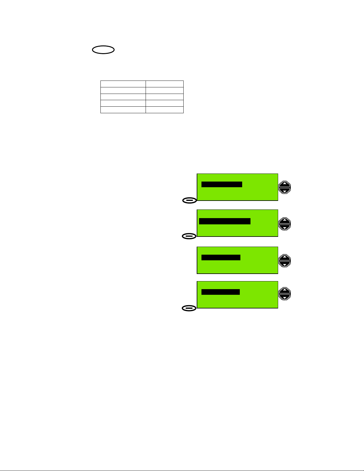
To change the mute status of the speakers:
1. In standby mode, press Menu.
2. Press the Scroll Up key to select
Profiles.
3. When Profiles menu option is displayed
press Select action key.
4. In the Profiles menu
Scan Dwell Time is shown as the first item.
Press the Scroll Down key
4 times to display the Speaker Settings
option.
5. The Profiles menu display now shows
Speaker Settings.
Press Select.
6. Scroll to the desired speaker mute option:
Int/Ext: on/off
Int/Ext: on/on
Int/Ext: off/off
Int/Ext: off/on
50°56'N at:08:41
001°34'E UTC
Menu
Send DSC Messages
Select Exit
Profiles
Select Exit
Scan dwell time
Select Back
Speaker settings
Select Back
Int/Ext: on/off
Select Back
68 Pos
Profiles
Profiles
Speaker settings
Then press Select.
7. In the example both speakers will be
unmuted. Press Select action key to execute
the change and return to standby mode.
NOTE: Alarm tones will not be muted.
Int/Ext: on/on
Speaker Settings
Select Back
Page 11
Page 22
Display and Keyboard Dimming
The LCD (Liquid Crystal Display) backlight illumination level can be changed using
light
the key.
Each press of the light key will cycle through different combinations of illumination
levels for display and keyboard as listed here:
Display Keyboard
DIM ON
FULL ON
OFF OFF
DIM (reversed) ON
Auto Dim
The F1 radio provides an Auto Dim feature.
The default state is Auto Dim ‘On’. In this state if the display backlight is set to ‘Full’,
after 5 minutes with no activity, the display backlight will be set to ‘Dim’.
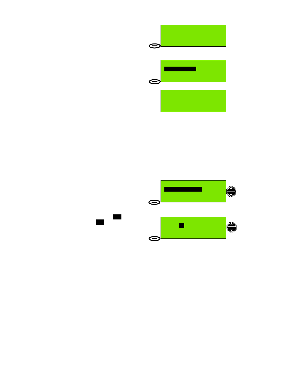
To switch off the Auto Dim feature:
1. Press Menu, then use the Scroll keys to
highlight Profiles, then press Select. Now
use the Scroll keys to highlight Display
settings in the Profiles menu, then press
Select.
2. In the Display Settings menu, use the
Scroll keys to highlight Automatic Dim
On/Off, then press Select.
3. The Automatic Dim On/Off state is On.
Use the Scroll keys to change state to Off.
4. Finally press Select to execute the
change and exit.
Page 12
Display settings
Profiles
Select Back
Display settings
AutomaticDim On/Off
Automatic Dim On/Off
On
Select Back
Automatic Dim On/Off
Off
Select Back
Page 23

Basic DSC Operations
All DSC communication is on Channel 70. The radio maintains a continuous watch
on this channel for incoming messages, which are immediately reported. This
monitoring also allows the system to transmit only when the channel is free.
Receiving an Individual DSC Call
When the radio receives an individual DSC message an alarm will sound, and the
message Individual Call is displayed.
If the call type is 'Distress' or 'Urgency' the
alarm ('notify beep') will sound repeatedly
every second. This screen will remain until
you Read the message or Exit.
Read
Individual Call
16 Exit
To read the message:
1. Press Read action key (or any key).
[Press Read]
Alarm tone is cancelled.
2. Press Read
key again to go to Read mode.
NOTE: If the call type is ‘Safety’ or
‘Routine’ the alarm will sound twice only.
If the message is not read within 1 minute
the radio will return to standby mode.
Individual: Safety
15 Jan 02 UTC:07:43
From stn: 987654321
Select
[Press Read]
16 Back
3. The Read mode screen is displayed,
and the message details are now shown; if necessary, scroll up and down to display
the complete message. To acknowledge the message press Select.
4. You now have a choice:
Transmit Acknowledge?
• Yes (default)
• No.
Transmit acknowledge
Yes
Select Back
Use the scroll keys to change the option
to acknowledge the received message.
NOTE: Normal practice is to acknowledge a
received DSC message, especially Distress or
Urgency messages.
5. Press Select to transmit a DSC
acknowledgement. A DSC Acknowledge
Acknowledge sent
Called stn:987654321
message is transmitted and the display briefly
shows Acknowledge sent and the MMSI of
the called station. The radio now switches to
the caller proposed channel ready for
communication. Press Reset to restore the
original channel, if desired.
50°56'N at:08:41
001°34'E UTC
6 Pos
Reset
Page 13
Page 24

Transmitting a DSC Call to a Ship Station
(
)
To transmit a call to a ship station
(individual call):
1. Press Menu action key to display top level
menu selection; (Send DSC messages).
50°56'N at:08:41
001°34'E UTC
Menu
16 Pos
2. Press Select action key to display the
Send DSC Messages menu.
3. The first (default) option displayed in the
Send DSC Messages menu is
Individual or group.
This call is to an individual station so press
Select to display the
Individual or group menu.
4. The first option displayed in the
Individual or group menu is
Called stn MMSI.
If you know the MMSI of the ship station
press Select to display the
Called stn MMSI entry screen.
5. Use the numeric keys to enter the MMSI,
and Clear to backspace and correct any error.
Ensure 9 digits are entered, then press
Select.
when MMSI entered
6. Now the radio prompts for a working
channel number to include in the DSC
message. If the current channel is OK press
Send, otherwise use the scroll keys or
numeric keys to change the channel, then
press Send.
Send DSC Messages
Select Exit
Send DSC Messages
Individual or group
Select Back
Individual or group
Called stn MMSI
Select Back
Called stn MMSI
MMSI:2091107
Select Clear
Individual Call
Call stn: 209110734
Working Channel:
Send Back
6
7. The message is now transmitted and the
radio display now shows Wait for
Acknowledge.
The radio will remain in this state waiting for
Individual Call
Call stn: 209110734
Wait for Acknowledge
Reset Back
acknowledgement for 5 minutes, or until
Reset is pressed.
If acknowledgement is received the radio switches to the specified working channel
(normally channel 6) to allow verbal communication.
Page 14
Page 25

Transmitting an Individual DSC Call Using Called Station Name
To Transmit an Individual Call Using Station
Name:
1. Press Menu action key to display top level
menu selection; (Send DSC messages).
50°56'N at:08:41
001°34'E UTC
Menu
16 Pos
2. Press Select action key to display the
Send DSC Messages menu.
Send DSC Messages
3. The first (default) option displayed in the
Select Exit
Send DSC Messages menu is
Individual or group.
This call is to an individual station so press
Send DSC Messages
Individual or group
Select to display the
Individual or group menu.
4. The first option displayed in the
Individual or group menu is
Called stn MMSI.
Use the Scroll keys to change the option to
Select Back
Individual or group
Called stn Name
Select Back
Called stn Name then press Select.
5. The display shows Called stn Name and
a station name. The example here is
Called stn Name
SeaMist
Name:
SeaMist. Use the Scroll keys to move through
the directory and change the station name.
Select Back
The numeric keys also have an alternate
function, allowing characters to be entered. Using this feature it is possible to enter
the initial character for the station name, which causes the F1 radio to search for
that name. If the F1 finds the name it will display the station name and MMSI ready
for a DSC transmission. If not it will attempt to display the closest alphabetically
matched name from the directory. For more details on this feature see the
‘Directory : Adding a Directory Entry’ section of this manual.
When the desired station name is displayed press Select.
6. Now the radio prompts for a working
channel number to include in the DSC
message. If the current channel is OK press
Send, otherwise use the scroll keys or
Individual Call
Call stn: SeaMist
Working Channel:
Send Back
6
numeric keys to change the channel,
then press Send.
The message is now transmitted and the radio
display shows Wait for Acknowledge. The
radio will remain in this state waiting for
Individual Call
Call stn: SeaMist
Wait for Acknowledge
Reset Back
acknowledge for 5 minutes or until Reset is pressed.
If acknowledgement is received the radio switches to the specified working channel
(normally channel 6) to allow verbal communication.
Page 15
Page 26

Transmitting a Call to a Coast (Shore) Station
When calling a Coast Station (ie a fixed installation whose MMSI number begins
’00….’), it is that station which selects the channel number for communication. As a
consequence, it is necessary to wait for the acknowledgement as this contains the
calling channel number.
Calling a Coast Station produces a prompt Insert position Yes; to select
No’, use the scroll keys. (This replaces the working channel selection, which
‘
is not used in the outgoing call; however, it is often useful for the Coast
Station to know the position of the calling vessel.)
To Transmit a Call to a Coast Station:
1. Press Menu action key to display top level
menu selection; (Send DSC messages).
2. Press Select action key to display the
Send DSC Messages menu.
3. The first (default) option displayed in the
Send DSC Messages menu is
Individual or group.
This call is to an individual station so press
Select to display the
Individual or group menu.
4. The first option displayed in the
Individual or group menu is
Called stn MMSI.
If you know the MMSI of the Coast Station
press Select to display the
Called stn MMSI entry screen.
7
50°56'N at:08:41
001°34'E UTC
Menu
Send DSC Messages
Select Exit
Send DSC Messages
Individual or group
Select Back
Called stn MMSI
Select Back
16 Pos
Individual or group
7
If you want to make a Station Name Call to the Coast Station, follow the procedure outlined in 'Transmitting an Individual
DSC Call Using Called Station Name' page 15, steps 4-5, and select a station name associated with a coast station MMSI,
then proceed to complete steps 6-8 in this section 'Transmitting an Individual DSC Call to a Coast (Shore) Station Name', on
page 17.
Page 16
Page 27

5. Use the numeric keys to enter the MMSI,
(
)
and Clear to backspace and correct any error.
Ensure 9 digits are entered, then press
Select.
when MMSI entered
6. The radio recognises the '00' prefix as a Coast
Station call; the display changes to
Coast station Call and you are prompted to
insert a position
(to be sent with the transmission).
If you do not want to include your position in
the message, use the scroll keys to change
the prompt from ‘
Yes’ to ‘No’.
Called stn MMSI
MMSI:00232144
Select Clear
Coast station Call
Call stn:002321447
Insert position
Select Back
Yes
7. The message is now ready to be sent.
The left action key has now changed from
Select to Send.
Press Send.
8. The message is now transmitted and the
radio display now shows
Wait for Acknowledge.
The radio will remain on this state waiting for
acknowledge for 5 minutes or until Reset is
pressed.
If acknowledgement is received, the calling
station acknowledge message includes the
channel for verbal communication. The F1
radio will then switch to that channel. In this
example the Coast Station selected channel
22.
Coast station Call
Call stn:002321447
Send Back
Coast station Call
Call stn:002321447
Wait for Acknowledge
Reset Back
50°56'N at:08:41
001°34'E UTC
Menu
22 Pos
Page 17
Page 28

Transmitting a Call to a Group
(
)
When calling a group of stations (i.e. stations all of which share a group MMSI
number, which begins ’0….’), no DSC acknowledgement is required or possible.
To Transmit a Call to a Group of Stations:
1. Press Menu action key to display top level
menu selection; Send DSC messages.
2. Press Select action key to display the
Send DSC Messages menu.
3. The first (default) option displayed in the
Send DSC Messages menu is
Individual or group.
This call is to a group so press Select to display
the Individual or group menu.
4. The first option displayed in the
Individual or group menu is
Called stn MMSI.
If you know the MMSI of the group you wish
to contact press Select to display the
Called stn MMSI entry screen.
5. Use the numeric keys to enter the MMSI, and
Clear to backspace and correct any error.
Ensure 9 digits are entered, then press Select.
when MMSI entered
6. The radio recognises the '0' prefix as a group
call; the display changes to Group Call,
and the radio prompts for a working channel
number to include in the DSC message. If the
working channel is not OK, use the
Scroll keys or numeric keys to change the
channel, then press Send.
50°56'N at:08:41
001°34'E UTC
Menu
Send DSC Messages
Select Exit
Send DSC Messages
Individual or group
Select Back
Called stn MMSI
Select Back
16 Pos
Individual or group
Called stn MMSI
MMSI:021172222
Select Clear
Group Call
Call stn:021172222
Working Channel:
Send Back
6
7. The message is now transmitted to the group,
the radio channel changes to the working
channel and the left action key now has the
function Reset. The radio will remain in this
state for 30 seconds or until Reset or PTT key is
pressed.
Note: To transmit an All Ships Call see page 31.
Page 18
50°56'N at:08:42
001°35'E UTC
6 Pos
Reset
Page 29

Full Telephony Operations
Changing the Priority Channel
The Priority Channel is the channel which is always monitored, and is selected
when the transceiver is switched on. The Priority Channel is normally set to
Channel 16, but it can be changed to any available channel by the operator.
To Change the Priority Channel:
1. Press Menu action key to display top level
menu selection; Send DSC messages.
2. Press the Scroll Up key to display the
Profiles menu.
3. Press Select.
4. The first option displayed in the Profiles
menu is Scan dwell time.
Press the down scroll key 3 times until the
option displayed is Channel mode then press
Select.
50°56'N at:08:41
001°34'E UTC
Menu
Send DSC Messages
Select Exit
Profiles
Select Exit
16 Pos
Profiles
Scan dwell time
Select Back
5. The first option in the Profiles menu is
Channel mode. Press Select.
6. The option (setting) displayed in the Channel
mode menu is either International
or US.
Press Select.
7. The radio prompts for the Priority Channel
number (highlighted). Use the scroll keys or
numeric keypad to change the Priority
channel, then press Select.
Channel mode
Select Back
Scanning priority
Channel:
Select Back
Profiles
16
Page 19
Page 30

Dual watch
The feature allows the radio to monitor automatically both the Priority Channel and
a selected additional channel.
To use the Dual Watch function, first set the radio to the desired channel, then push
dual
the key.
The display will alternately display selected
channel number and channel 16, at a rate
Dual watch : 11&16
which is controlled by the Scan Dwell Time
(refer to the 'Setting Profiles' section for
Menu
16 Pos
information on this parameter).
Pressing the key again cancels the
Dual Watch and returns the radio to a listening
dual
Dual watch : 11&16
watch on the channel at which the Dual Watch
function is stopped.
Menu
11 Pos
The following points describe Dual Watch in more detail:
• The Additional Channel can be any available channel.
• Dual Watch starts by watching the Additional Channel for 850 milliseconds
(ms), then sampling the Priority Channel for 150ms, and returning to the
Additional Channel for 850ms. This sequence continues until activity is
detected on one of the channels.
• If activity is detected on the Priority Channel the scanning sequence will be
stopped for the duration of the activity and Priority Channel will be displayed in
large characters.
• If activity is detected on the Additional Channel, then the Additional Channel
will be monitored for 1.8 seconds and the Priority Channel will be monitored for
150ms.
• The Dual Watch function can be stopped at anytime by pressing the
dual
key. The radio is then set to the channel at which the Dual Watch function is
stopped.
Page 20
Page 31

Channel scanning
Channels may be sequentially monitored for activity using the Channel Scanning
facility of the F1 radio.
While scanning the radio automatically maintains a watch on a channel for the
duration of the set dwell time. The dwell time can be set in the Profiles menu. If no
signal is detected the radio moves to the next channel in the sequence of channels,
which may be the next consecutive channel.
Scan program
Scanning is controlled by Scan Programs (lists of channels to scan) which are
stored in the F1 radio. You can store up to 9 different scan programs
To summarise the features of the Scan Program facility:
• The transceiver has 10 scan programs (including ‘Scan All’).
• When ‘Scan All’ is selected all channels available to the operator will be
scanned.
• Each Scan Program can be configured individually
• The numbers of channels in an individual scan program is limited to 30 (except
for the Scan All program.
• All channels available to the operator can be programmed into a scan
sequence
• The operator can set the Channel Dwell Time within the range
200 milliseconds (ms) to 1.8 seconds, in steps of 50 ms.
• The Channel Dwell Time can only be varied for the channels in the Scan
Program. (The dwell time for the Priority Channel remains 150 ms.)
To setup the radio for scanning refer to the ‘Scanning All Channels: Creating and
Editing a Scan Program’ section.
Incoming DSC Call During Scanning and Dual Watch
During Scan or Dual Watch incoming DSC calls will be displayed as incoming calls
for 1 minute. When the 1 minute period has elapsed the radio will return to the Dual
Watch or Scan operation, and the LCD screen shows the Scan or Dual Watch
display, as appropriate. A message symbol (
message has been received.
However if the incoming call is an All Ships Call of the Category ‘Distress, Urgency
or Safety’ the display will continue to show the incoming call and the Scan and Dual
Watch activity will be stopped. In this situation the Scan and Dual Watch activity has
to be reactivated by the operator.
IMPORTANT: The Scan Program only defines the channels to be used from the
legal channels available when the radio is configured by your supplier. It is the
responsibility of the user to ensure that the radio is operating in the correct
channel mode (i.e. International or US) before initiating a scan.
/) is displayed if an unread DSC
Page 21
Page 32

Scanning All Channels
To Scan All Channels:
1. Press Menu action key to display top level
menu selection; Send DSC messages.
2. Use the Scroll keys to display the
Channel scanning menu.
3. Press Select.
50°56'N at:08:41
001°34'E UTC
Menu
Send DSC Messages
Select Exit
Channel scanning
Select Exit
16 Pos
4. The first option displayed in the
Channel scanning menu is Run scan
program.
Press Select.
5. The first option displayed in the
Run scan program menu is Scan:
ALL.
Press Select.
6. The scan program is now running. The
Channel scanning
Run scan program
Select Back
Run scan program
ALL
Scan:
Select Back
Scan:ALL run
Scan: ALL run screen is displayed.
27 Back
The channel is incremented every X ms,
Stop
where X is the dwell time, and every 1.8
seconds the Priority Channel (normally Channel 16) is monitored for activity. If
activity is detected on any channel the radio will stop scanning and channel on
which activity was selected will remain selected. After 5 seconds of no activity on
the channel, the radio will resume scanning. Squelch level should be adjusted for
correct operation. If the squelch level is too low (control too far counter-clockwise),
scanning will halt. If the squelch level is too high (control too far clockwise), weak
signals may not be heard.
NOTE: During channel scan, channels with a 1W maximum allowable transmission
power requirement cause the radio to select 1W power for those channels.
Page 22
Page 33
Inhibiting a Channel
To Inhibit a Channel when Scanning:
Scan:ALL run
1. The scan program is now running.
The Scan ALL run screen is displayed.
Stop
24 Back
Press Stop.
2. The screen now displays the new scan
status:
Inhibit chXX, where XX was the channel
when Stop was pressed. Example: Ch25.
Scan:ALL stopped
Inhibit ch25
Select Run
Press Select.
The scan program is now running again,
Scan:ALL run
But channel 25 is now temporarily deleted
26 Back
from the list of channels to be scanned, and
Stop
the radio will skip over channel 25 when
selecting channels during the scan process.
Channel inhibition can be applied to additional channels, and is performed exactly
as described in steps 1 and 2 above.
To restore the original 'Scan All' state (all channels scanned) press the Back key
then the Select key. Scanning is then resumed for all channels.
Running a Scan Program (1-9)
To Run a Scan Program (Scan Program 1 to Scan Program 9):
1. In standby screen, press Menu, then scroll
to Channel scanning and press Select.
Channel scanning
Run scan program
Select Back
2. Scroll to Run scan program and press
Select.
3. Display shows Scan:
Scroll to Scan:
01 (or to the Scan Program of
your choice. When the desired Scan Program
is displayed press Select to start the Scan
Program.
ALL.
Run scan program
Scan:
Select Back
01
[See also ‘Full Telephony Operations: Creating and Editing a Scan Program’ page
24.]
Page 23
Page 34

Creating and Editing a Scan Program
To Create (and Edit) a Scan Program:
1. Press Menu action key to display top level
menu selection; Send DSC messages.
2. Use the Scroll keys to display the
Channel scanning menu.
50°56'N at:08:41
001°34'E UTC
Menu
Send DSC Messages
Select Exit
16 Pos
3. Press Select.
4. The first option displayed in the Channel
scanning menu is Run scan program.
Use the Scroll keys to display the
Edit scan program menu.
Press Select.
5. The first option displayed in the
Edit scan program menu is Scan:
ALL.
Use the scroll keys to highlight a Scan
Program to create or edit.
(Scan programs
01 to 09 are available).
Press Select.
6. Scan Program
01 is used in this
example.
Press Select to begin editing the program.
7. Edit screen for Scan Program
01 is
displayed. No channels entries have been
found in this Scan program so the first channel
entry (number 1, of a possible 30 entries) is
shown with the channel number field displayed
xxx (blank entry).
as
Channel scanning
Select Exit
Channel scanning
Run scan program
Select Back
Edit scan program
Scan:
Select Back
Scan:
Select Back
Scan: 01 edit
1:
Store Delete
ALL
Edit scan program
01
xxx
Page 24
Page 35

8. To make a scan table containing the following entries:
Scan Program
01
Entry Channel
111
213
3 6
410
567
Press numeric key ‘1’ twice to enter
‘Channel 11’.
First press of the numeric key displays
1
second press displays 11. 2 seconds after
Scan: 01 edit
xxx
1:
Store Delete
the last key press, the radio will move to the
next entry, ready for editing, so edit each
channel by pressing the numeric keys quickly.
9. The second entry is now highlighted
ready for editing (vacant channel entry
position). Enter
13 and wait for 2 seconds for
the radio to move down the list and highlight
xxx
Scan: 01 edit
1: 11
xxx
2:
Store Delete
the third entry.
If you make a mistake, or want to change an entry, use the Scroll Up key to
highlight and re-edit the entry, then continue adding entries as normal. (If the entry
you re-edited was several entries further up the list, use Scroll Down to move past
the correct entries until the first vacant entry position is again highlighted.)
10. Continue to enter channel numbers into
the remaining entries 3 to 5.
Press Store to save the Scan Program.
11. Display confirms Scan program stored,
then returns to the Edit scan program
selection screen.
You can either create/edit another scan
program (use the scroll keys to select Scan
Program
02, for example) or move up to a
higher menu level (or to the standby screen)
by pressing the Back / Exit key.
Scan: 01 edit
5: 67
xxx
6:
Store Delete
Edit scan program
Scan:
Select Back
01
Page 25
Page 36

DISTRESS
Rapid Distress Call
IMPORTANT:
To send a Distress Call,
(without designating the distress type),
do this:
1. Open the Distress Button cover.
2. Press and hold the Distress Button.
Keep pressing the button.
DISTRESS
You will hear an Alarm Tone.
3. The display will show different screens
and may prompt you for more information.
Ignore the prompts.
Keep pressing the button
until you see this screen.
4. If you have sufficient time transmit a voice distress message
(If possible wait 15 seconds for any DSC acknowledgement before transmitting.)
Pick up the microphone, press the PTT (TALK) button and call for help:
‘MAYDAY, MAYDAY, MAYDAY
This is Ship name, Ship name, Ship name
MAYDAY
This is Ship name, Callsign.
Position:……………………………….
Nature of distress:…….……………..
Help needed:………………………….
(any other information)
OVER’
IMPORTANT: Do NOT make a distress call unless there is grave and imminent
danger. It is an offence to make any unjustified distress call.
Distress Call
Undesignated
Wait for Acknowledge
Reset
16
Page 26
Page 37

Full DSC operations
Distress Call Including Nature of Distress
To make a Distress Call including Nature of Distress (Method 1):
(GPS connected)
1. Open the Distress Button cover.
2. Press the Distress Button
for less than 5 seconds.
(A 1 second push is sufficient.)
DISTRESS
You will hear an Alarm Tone.
3. The radio displays the Pre-Distress Warning
screen. You can choose:
• not to send a Distress Message
(press Back)
or
• continue to the Distress Options
(press Options).
NOTE: This sequence applies to a
radio with GPS connected
(position available).
4. The display now shows the Nature of
Distress menu.
Undesignated distress is the first option.
To select a different Nature of Distress option
use the Scroll keys to scroll through the list of
options.
5. When you see the Distress option you need,
press Select.
Example: Collision.
Distress Call
Hold for
or quit for options Options
Back
Nature of Distress
Undesignated
Grounding
Piracy,armed robbery
Nature of Distress
Collision
Select Back
5 seconds
Fire, Explosion
Flooding
Collision
Listing, capsizing
Sinking
Disabled and adrift
Abandoning ship
Man overboard
Page 27
Page 38

6. Press and hold the Distress Button for at
least 5 seconds.
DISTRESS
You will hear an Alarm Tone.
7. Display shows ‘Distress Call’ and an
instruction to hold the Distress Button for
5
seconds.
8. Continue to hold the Distress Button, display
shows a countdown number, in seconds, until
the Distress Message is sent.
Count is from
5 down to 0 seconds before the
Distress Message is transmitted.
WARNING: If you release the Distress
Button before 5 seconds has elapsed the
Distress Message is not transmitted.
Instead the display will revert to the
Distress Call setup screen shown in step 3.
9. When count reaches
0 a Distress Call
(including Distress Category) is transmitted,
and the radio selects channel 16.
10. The F1 radio waits for acknowledgement of
the Distress Message.
Distress Call
Hold for
or quit for options
Distress Call
Hold for
or quit for options
Distress Call
Hold for
or quit for options
Distress Call
Collision
Wait for Acknowledge
Reset
5 seconds
4 seconds
0 seconds
16
11. If no acknowledgement received the F1
radio will wait for a random time between 3.5
and 4.5 minutes, then automatically retransmit
the Distress alert. The radio will continue to
retransmit the Distress message every 3.5 to
4.5 minutes until acknowledgement is received
or Reset is pressed.
Page 28
Not acknowledged
Distress alert
Retransmission
Reset
16
Page 39

12. If an acknowledgement is received the
display shows Distress acknowledge
received for 4 seconds, then the state is
changed to Distress in progress.
Distress acknowledge
received
13. Distress in progress screen is displayed
after an acknowledgement or if Reset is
Distress in progress
pressed.
16
Reset
In the 'Distress in progress' state, the distress
message is not re-transmitted.
14. Wait approximately 15 seconds for an acknowledgement before transmitting a
voice MAYDAY, as described on Page 26 step 4.
IMPORTANT: Do NOT make a distress call unless there is grave and imminent
danger. It is an offence to make any unjustified distress call.
Page 29
Page 40

To make a Distress Call including Nature of Distress (Method 2):
A
(GPS unavailable)
1. Open the Distress Button cover.
2. Press the Distress Button
for less than 5 seconds.
(A 1 second push is sufficient.)
DISTRESS
DISTRESS
You will hear an Alarm Tone.
3a. The radio displays the Pre-Distress
Warning screen.
Distress Call
Hold for
or quit for options Options
Back
5 seconds
3b. No position information is available; display
shows, briefly Position too old.
Distress Call
ssumes that position and time information not
entered when radio switched on, or that this
information is more than 4 hours old.
Position too old
quit for update
3c. Radio prompts for your position and time (either local if local time offset value is
known) or UTC as standard. Enter your position as described in ‘Basic Telephony
Operations’ / ‘Entering Time and Position’.
3d. Position and Time information is now valid;
You can choose:
• not to send a Distress Message
Lat: --°--'Long: ---°--'Pos at:--:-- UTC
Done Back
(press Back)
or
• to enter your position
- use numeric, *, #, and scroll keys,
(then press Done)
or
• to continue to the Distress Options
(press Options)
or
• to override the position entry prompt
to continue to the Distress Options
(keep pressing and holding
Distress Button).
Distress Call
Hold for
or quit for options Options
Back
5 seconds
Now apply steps 4-14 in the section 'To make a Distress Call including Nature
of Distress (Method 1)', page 27-28.
Page 30
Page 41

Transmitting an All Ships Call
(
y)
When sending an All Ships message, no DSC acknowledgement is required or
possible. Obviously, an All Ships call is not addressed to a specific station and so
does not need the details of the called party; it does, however, give the choice of
Safety or Urgency messages.
An Urgency message is used when safety is threatened but there is no
imminent danger. The verbal information transmitted after an Urgency
message is prefixed ‘PAN PAN’
A Safety message concerns important navigational or meteorological
information. The verbal information transmitted after a Safety message is
prefixed ‘SECURITÉ SECURITÉ SECURITÉ’.
To transmit an All Ships call:
1. Press Menu action key to display top level
menu selection; Send DSC messages.
2. Press Select action key to display the
Send DSC Messages menu.
3. The first (default) option displayed in the
Send DSC Messages menu is
Individual or group, so use the Scroll keys to
change the option to All Ships,
then press Select.
4. The first option displayed in the
All Ships Call menu is Urgency.
Select Urgency or Safet
5. If your message is not of the type ‘Urgency’
use the Scroll keys to change the option to
Safety.
Now press Select.
50°56'N at:08:41
001°34'E UTC
Menu
Send DSC Messages
Select Exit
All Ships
Select Back
Urgency
Select Back
Safety
Select Back
16 Pos
Send DSC Messages
All Ships Call
All Ships Call
Page 31
Page 42

6. The radio prompts for a working channel
number to include in the DSC message. If the
default working channel is not suitable use the
scroll keys or numeric keys to change the
channel, then press Send.
All Ships Call
Safety
Working Channel:
Send Back
6
7. The message is now transmitted to
All Ships.
50°56'N at:08:42
001°35'E UTC
6 Pos
Reset
If acknowledgement is received, the radio
channel changes to the working channel and
the left action key now has the function Reset.
The radio will remain on this state for 30 seconds or until Reset or PTT is pressed,
then it will revert to a listening watch (standby screen).
Page 32
Page 43

Received message log
The radio retains two lists of received messages, one for Distress and All Ships
calls, and one for all other calls. Any message which is unread causes an indicator
/ ) to be displayed when the radio is in listening mode.
(
These lists each retain 20 calls; when a list is full, a new call overwrites the oldest
call in the list.
To read received DSC messages:
1. (In standby screen) press the Menu key.
2. Use the scroll keys to highlight the
Received Messages option in the menu.
3. Press Select.
4. Distress Messages are listed first. If you
wish to read the Distress Messages log, press
Select, otherwise (as in this example) use the
scroll keys to highlight Ordinary Messages.
5. Press Select.
(If no messages are stored the display
shows Log empty.)
6. The number of messages are listed
(maximum 20) together with an
indication of the message to select (and
the date that message was received.
Press Read.
50°56'N at:08:40
001°34'E
Menu 11 Pos
Send DSC Messages
Select Exit
Received Messages
Select Exit
Distress Messages
Select Back
Ordinary Messages
Select Back
Message:
Received:03 Mar 02
Read Back
/
Ordinary Messages
1 of 2
7. The details of the call are now
displayed. In this example an Individual
call of routine category was made at
7:52 UTC, the calling station MMSI was
987654321, and the working channel is
channel 6.
Individual:Routine
03 Mar 02 UTC:07:52
From stn: 987654321
6 Back
Select
Page 33
Page 44

8. To acknowledge the message press
Select, otherwise use the scroll keys to
highlight No and press Select, or press
Back.
Transmit acknowledge
Yes
Select Back
9. If Back is pressed the screen returns to the
list of received DSC messages.
Message
1 now has a character ‘R’ attribute.
This indicates that the message has been
read.
10. To read more messages use the scroll
keys to highlight the appropriate message
number, then repeat steps 6 to 8 to read /
acknowledge the message(s).
11. If you return to the standby screen (and all
messages have been read) the
/ is
Ordinary Messages
Message:
Received:03 Mar 02 R
Read Back
Message:
Received:03 Mar 02
Read Back
1 of 2
Ordinary Messages
2 of 2
50°56'N at:08:44
001°34'E UTC
removed.
Menu
11 Pos
Distress (and Urgency) messages are treated in exactly the same way, but are
stored (and accessed from) the Distress Log.
As is usual with all such messages, the complete text of the message can be read
by scrolling up and down.
Note: While a call is being displayed, the left Action key shows Select if no
acknowledgement has been sent (and the message is of the type which can be
acknowledged) or Reset if the message has been acknowledged. In the first case,
pressing Select produces a prompt to acknowledge the message. It is thus possible
to defer the acknowledgement of messages until a convenient time; the sender will
then be informed that the called party (i.e. you) is now ready to communicate.
Page 34
Page 45

Directory
The directory allows the user to store the names of vessels, coast/shore stations,
etc together with the corresponding MMSI. A total of 50 entries may be stored. The
directory may be searched for a particular name; entries may be added and erased.
Adding a Directory Entry
To Add an Entry to the Directory:
1. Press Menu and scroll to Directory.
Press Select and scroll to Add Entry.
2. Press Select.
Directory
Select Exit
Directory
Add Entry
Select Back
3. The cursor appears at the first character of
the station name. In the Directory-Add Entry
screen, the numeric keys can be used to enter
alphabetic values, as printed beside each key.
See ‘Appendix A: Character Entry’ for more
Directory:Add entry
Stn name:|
Stn MMSI:
Save
details.
4. Characters are added from the keyboard by
pressing the appropriate key to cycle through
the available letters (eg to enter ‘n’, press the
‘6’ key twice). Once a character is entered, the
Directory:Add entry
Stn name:Se|
Stn MMSI:
Save Clear
next character can be entered immediately
provided it is set by a different key. If the same key must be used (for example, to
enter ‘e’ after entering ‘d’), wait two seconds after the key was last pressed for the
cursor to move to the next character position.
In the example screen the first 2 characters of the name ‘
#
#
for upper-case, followed by 4 presses of the key, the
again (lowercase) , then 2 presses of the key.
Seamist’ are entered;
7pqrs
3def
5. If an incorrect character is entered, the Clear key deletes the last character. If an
error is noticed in the middle of an entry, use the Scroll keys to move the cursor to
the right of the erroneous character, then press Clear to delete it. The new
character can be entered at the cursor position as described in steps 4 and 5.
To enter the MMSI number, scroll down to the line Stn MMSI. The keys return to
numeric mode. Enter the MMSI number using the numeric keys.
When both the name and MMSI number are correct, press Save. The display will
confirm that the entry has been saved. Names are saved in alphabetic order in the
directory. If an entry is incorrect, it cannot be edited once it has been saved. The
entry must be erased, re-entered and saved again.
Page 35
Page 46

Erasing a Directory Entry
To Erase a Directory Entry:
1. Press Menu, scroll to Directory,
and press Select.
2. Scroll to Erase and press Select.
3. The display shows the first Station Name
entry (list in alphabetic order) and MMSI
number. Scroll through the list of names (or
enter an initial character using the character
entry method described in ‘Adding a
Directory Entry’, steps 4 and 5) to find the
desired entry.
4. Press Erase. The display will confirm that
the entry has been erased.
Search for a Directory Entry
To Search for a Directory Entry:
1. Press Menu, scroll to Directory,
and press Select.
2. Search is the first displayed Directory
option. Press Select.
Directory
Erase
Select Back
Directory:Erase
Stn name:
Stn MMSI:
Erase Back
SeaMist
Erased from
Directory
Directory
Select Exit
Directory
Search
Select Back
SeaMist
3. The display shows the first Station Name
entry (list in alphabetic order) and MMSI
number. Scroll through the list of names (or
enter the first character using the character
Directory:Search
Stn name:
Stn MMSI:111100000
Edit Back
SeaMist
entry method described in ‘Adding a Directory
Entry’, steps 4 and 5) to find the desired entry, (wait until the first name starting with
that letter is displayed, then the other names which also start with the same letter
can then be accessed by scrolling. This method is much faster for finding names
towards the end of the alphabet, particularly if the list is full).
Individual or Group Calls Using the Directory
To Transmit DSC Calls Using a Station or Group Names from the Directory:
Please refer to the ‘Basic DSC Operations: Transmitting an Individual DSC Call
Using Called Station Name’ section, page 15. The Group Stations are accessed,
using the directory, in the same way as Individual Stations.
Page 36
Page 47

Setting Profiles
The radio cannot be used to transmit in DSC mode until, as a minimum, its MMSI
number has been programmed into it.
Setting the MMSI Number
The MMSI (Maritime Mobile Service Identity) number is a 9-digit identifier which
enables a registered vessel to be identified.
MMSI numbers are of three types: individual, group and coast station.
• An Individual Number identifies a single radio installation.
• A Group Number is an assigned number which allows several vessels
to receive a single addressed call (example: a fleet of vessels). Group
Numbers always start ‘0….’
• A Coast Station number identifies a fixed installation
e.g. a Coastguard radio. Such numbers always start ‘00…’
When the radio is purchased, the supplier may configure the radio with the correct
individual MMSI; otherwise, the MMSI number is normally set to 000000000. This
must be changed before the radio can transmit in DSC mode.
NOTE: Only one individual MMSI number may be stored in the radio.
If the wrong MMSI number is stored, only a Service Agent can remove it.
2 MMSI entry attempts are allowed within 1 hour. Refer to Installation Manual.
1. From the standby screen, press the Menu
key.
Profiles
2. Scroll through the options to find Profiles.
Select Exit
Press the Select key.
3. Scroll to MMSI number and press Select.
4. The first option displayed in the MMSI
Profiles
MMSI number
Select Back
number menu is Ship MMSI number.
Press Select.
5. The MMSI number appears as 000000000;
this must first be cleared.
Press the Clear key repeatedly until the
number is blank. Carefully enter the correct
MMSI number using the numeric keys.
Incorrect entries can be erased using the
MMSI number
Ship MMSI
Select Back
Ship MMSI number
MMSI:000000000
Save Clear
Clear key.
6. When the number is correct, check it again. When you are satisfied that no error
has been made, press the Save key. The individual MMSI number is now saved in
the memory of the radio. It cannot be changed by the user.
Page 37
Page 48

Group MMSI Numbers
A radio may be a member of up to 4 MMSI groups (for example, a group MMSI
could be assigned to a fishing fleet).
Setting a group MMSI is similar to the process for setting the individual MMSI.
1. After selecting Profiles – MMSI number,
scroll to Group MMSI and press Select.
Group 1 is displayed first;
Groups 2, 3, and 4 are displayed by scrolling.
2. Press Edit to enter the Group MMSI
number. When entering the MMSI number, the
first ‘0’ cannot be changed (because it
identifies a MMSI as a group number). The
Back Action key changes to Clear as you
MMSI number
Group MMSI
Select Back
Group MMSI number
Group 1:
Edit Back
enter digits.
3. When the Group MMSI is entered, press
Save. The Edit screen, showing the group
MMSI is then displayed and it is possible to
Edit the number again, or use the Back / Exit
key to return to the standby screen.
Group MMSI number
Group 1:0|
Save Back
Unlike the individual MMSI number, Group MMSIs can be edited and deleted.
Scan Dwell Time
The Scan Dwell Time is the length of time the radio monitors each channel when in
Scan mode.
To set the Scan Dwell Time:
1. In standby screen, press Menu, then scroll
to Profiles and press Select.
Profiles
Select Exit
2. Scan dwell time is the first option
displayed. Press Select.
3. The Dwell Time is changed using the Scroll
keys. Time increments / decrements are
50ms. Press Save when the desired dwell
time is displayed.
Page 38
Profiles
Scan dwell time
Select Back
Scanning [msec]
Set dwell time: 200
Save Back
Page 49

Key Beep
The key beep volume may be set as high, low or off. This option is changed using
the scroll keys.
To set Key Beep mode:
1. In standby screen, press Menu, then scroll
to Profiles and press Select.
2. Scroll to Key beep and press Select.
3. Scroll through the selections Off / Low /
High. When the desired option appears press
Select.
Profiles
Select Exit
Profiles
Key beep
Select Back
Key beep
Off
Select Back
Channel Mode
This sets the frequency channels to International or US mode of operation. US
mode is used only when the vessel is in US waters. Again, selection is by the scroll
keys. Additionally, Priority Channel can be changed in this menu.
To set Channel Mode:
1. In standby screen, press Menu, then scroll
to Profiles and press Select.
2. Scroll to Channel mode and press Select.
Profiles
Select Exit
Profiles
Channel mode
3. Scroll between the options International
and US. When the desired option is displayed
press Select.
4. International mode is selected in this
example. Scanning priority channel may now
be set. Use either the scroll keys or numeric
keys to enter a new Priority Channel if desired.
Select Back
Channel mode
International
Select Back
Scanning priority
Channel:
Select Back
16
Page 39
Page 50

Speaker Settings
This control allows any combination of internal and external speakers to be active.
The four possibilities are selected by the scroll keys.
To set Speaker Options:
1. In standby screen, press Menu, then scroll
to Profiles and press Select.
2. Scroll to Speaker settings and press
Select.
3. Scroll through the Int/ext: (internal / external
speaker) selections. When the desired option
appears press Select.
Profiles
Speaker settings
Select Back
Speaker settings
Int/ext: on/off
Select Back
NOTE: Alarm tones cannot be muted.
See also Speaker Mute Function under Basic Telephony Operations.
Notify Beep Volume
This control sets the volume of the alert tone used to attract the attention of the
operator. The scroll keys change the volume level.
To set Notify Beep Volume:
1. In standby screen, press Menu, then scroll
to Profiles and press Select.
2. Scroll to Notify beep and press Select.
Profiles
Notify beep
Select Back
3. Scroll through volume levels 10-30. The
Notify beep is heard for each scroll action – at
a higher or lower volume for the appropriate
scroll direction. When the desired volume is
Notify beep
20
Select Back
reached press Select.
This control does not affect the Alarm level (volume), which is always =>90dBA.
Only the volume of warning beeps (Notify Beeps) used to alert the operator to
(example: bad GPS connection, data entry errors, etc.), is adjusted.
Page 40
Page 51

LCD Contrast Adjust
This control allows the contrast of the LCD display, and thus the viewing angle of
the screen, to be adjusted using the Scroll keys.
To set the Contrast Level:
1. In standby screen, press Menu, then scroll
to Profiles and press Select.
Profiles
Display settings
Select Back
2. Scroll to Display settings and press
Select.
3. The first option displayed in the Display
settings menu is LCD contrast adjust.
Press Select.
4. Scroll through contrast levels 0-30. When
the desired level is reached press Select.
(Default level is 15).
Display settings
LCD contrast adjust
Select Back
LCD contrast adjust
15
Select Back
If the screen becomes dark and cannot be adjusted by the scroll keys, press the
right action key (the Back button) to return to the previous setting.
Auto Dim
The F1 radio provides an Auto Dim feature.
The default state is Auto Dim ‘On’. In this state if the display backlight is set to ‘Full’,
after 5 minutes with no activity, the display backlight will be set to ‘Dim’.
To change the settings of this feature:
Profiles
Display settings
1. In standby screen, press Menu, then scroll
to Profiles and press Select.
Select Back
2. Scroll to Display settings and press
Select.
3. Scroll to Automatic Dim On/Off
Display settings
Automatic Dim On/Off
Select Back
and press Select.
Automatic Dim On/Off
On
4. Scroll between On and Off states. When
the desired state is shown press Select.
Select Back
[See also 'Basic Telephony operations: Display and Keyboard Dimming' section,
page 12.]
Page 41
Page 52

Software Version
This control displays the radio software version. No change is possible.
To display Software Version:
1. In standby screen, press Menu, then scroll
to Profiles and press Select.
2. Scroll to Software version and press
Profiles
Software version
Select Back
Select.
3. Software version is displayed. The version
number may differ from the version displayed
in your radio.
Software version
McM Fixed VHF
1.1
OK Back
4. Press OK to return to standby screen.
Position Indication
This controls whether the position information is displayed on-screen
(Display On/Off), and sets the format of the display (Enhanced position).
Enhanced position displays position in degrees, minutes and seconds.
To change the settings of this feature:
1. In standby screen, press Menu, then scroll
to Profiles and press Select.
2. Scroll to Position indication and press
Profiles
Position indication
Select Back
Select.
Position indication
3. Scroll between the options Display On/Off
and Enhanced position. When the desired
option appears press Select.
Display on/off
Select Back
4. Scroll between On and Off states for
Display On/Off or Enhanced position. When
the desired state is shown press Select.
The enhanced position is displayed only when
the Pos button is pressed in standby screen.
When enabled, it is also sent with a Distress
message.
Page 42
Display on/off
On
Select Back
Enhanced position
On
Select Back
Lat: 50°56'23"N
Long: 001°34'51"E
Pos at:08:44 UTC
Exit
Page 53

Time/Date and Offset
This control allows the time and date to be set (from the numeric keys).
Time may be displayed as UTC or as local; local time is set as an offset (number of
hours difference) from UTC. When setting the offset, the first position is the
positive/negative setting; pressing any numeric key or ‘
*’ or ‘#’ toggles ‘+’ or ‘–’.
To set Time and Date:
1. In standby screen, press Menu, then scroll to Profiles and press Select.
2. Scroll to Time/Date and Offset and press
Select.
Profiles
Time/Date and Offset
Select Back
3. The first option is Set Time/Date. Press
Select.
4. Use the scroll keys to move the cursor
position in the hh:mm field. Use the numeric
keys to change the time.
5. To complete the change and move to
the date entry screen, press Done.
6. Use the scroll keys to move the cursor
position in the DD:MM:YYYY field. Use the
numeric keys to change the date.
To set Time Offset:
1. In standby screen, press Menu, then scroll
to Profiles and press Select.
2. Scroll to Time/Date and Offset and
press Select.
3. Scroll to Set Time offset.
Press Select.
4. Use the scroll keys to move the cursor
position in the +00:00 field. Use the numeric
keys to change the time offset, and ‘
*’ key to
set ‘+’ or ‘–’ then press Done.
Time/Date and Offset
Set Time/Date
Select Back
Set Time:UTC
hh:mm
11:27
Done Back
Set Date:UTC
DD/MM/YYYY
21/03/2002
Save Back
Profiles
Time/Date and Offset
Select Back
Time/Date and Offset
Set Time offset
Select Back
Set Time offset
Local = UTC + offset
+00:00
Done Back
Page 43
Page 54

Radio Test
This control performs a self-test on the radio. The screen displays the result of the
test. The results, and actions to be taken, are discussed in ‘Appendix C: Error
Messages / Troubleshooting’.
To perform Radio Self Test:
1. In standby screen, press Menu, then scroll
to Profiles and press Select.
2. Scroll to Radio test and press Select.
3. There is only one test option in this radio
version. With Self test highlighted, press
Select.
4. Observe the progress of the test
(display shows Self test running) and watch
the indicator LEDs flash, progress bar (on
display) advance and hear the beeps which
track progress.
5. When the test is complete you should see
the message No errors found. If the display
shows anything else please refer to ‘Appendix
C: Error Messages / Troubleshooting’ for an
explanation.
Profiles
Radio test
Select Back
Radio test
Self test
Select Back
Self test running
Back
Radio test
No errors found
Back
Page 44
Page 55

APPENDICES
v
Appendix A: Character Entry
To enter station names using numeric keypad, use keys 0-9 to access letters a-z as
follows:
2abc
4ghi 5jkl
7pqrs
*
In a mode requiring alphanumeric entries, press the appropriate key (1 to 5
presses) until the desired character is displayed, as shown in the table below.
First
press
*
0
1
2abc
3def
4ghi
5jkl
+-*
-
1
a / A b / B c / C 2
d / D e / E f / F 3
g / G h / H i / I 4
j / J k / K l / L 5
8tu
0
Second
press
<SPC> 0
9wxyz
#
Third
press
3def
6mno
Fourth
press
Fifth
press
6mno
7pqrs
8tuv
9wxyz
#
m / M n / N o / O 6
p / P q / Q r / R s / S 7
t / T u / U v / V 8
w / W x / X y / Y z / Z 9
Toggles upper and lower case character entry.
Appendix Page 1
Page 56

Appendix B: Menu Hierarchy
*
*
Appendix Page 2
Page 57

Appendix Page 3
Page 58

Appendix C: Error messages / Troubleshooting
Problem Probable Cause / Solution
Radio cannot be switched on. 1. Poor connection to power supply / battery.
(Check connections.)
2. Fuse blown. (Inspect wires and fuse.)
No sound from radio. 1. Volume control set too low. (Rotate
volume control clockwise).
2. Squelch level too high. (Back off squelch –
rotate squelch control anticlockwise.)
3. Water in front of speaker. (Drain water.)
Radio will not scan (scan program
selected and running)
No sound heard from speaker 1. If, after setting volume and squelch
The radio performs a series of self tests when power is first switched on.
The mode-indicator and keyboard LEDs, plus LCD backlight, are cycled, and the
LCD display contrast settings are briefly exercised. During this sequence, internal
self tests (such as synthesiser lock and memory integrity) are performed and the
LCD display shows a progress bar during the test sequence. If errors are detected
the radio will display an error screen. Possible error screens are shown here, each
with an explanation.
1. The squelch level may be set incorrectly
for operation of scanning function. If the
squelch level is too low (control too far
counter-clockwise), scanning will halt. If
the squelch level is too high (control too far
clockwise), weak signals may not be
heard.
appropriately, sound still cannot be heard
then the internal speaker may be disabled.
(The transceiver is supplied with the
internal speaker enabled.) To re-enable
the speaker, go to Profiles -> Speaker
settings.
Power-Up Self-Tests (1)
Type of Test / Error Message Probable Cause / Solution
This may be caused by a checksum error or
Error observed
during
initialisation
See Operator Manual
Appendix Page 4
other internal fault. (If the error is still present
after the radio is switched off and on again,
then it will be necessary to consult a Service
Agent, because the radio may be using
incorrect information, and may try to operate
outside its design limits.)
Page 59

Pos update not found
source of GPS derived positional
information, via the NMEA port, and the
When the radio switches on, it tries to find a
Menu
16 Update
display message is ‘Search for Position’. If
no position information is detected within 2
minutes, the display message is ‘Pos update
not found’.
Error detected
Synth out of lock
See operators manual
Radio synthesiser lock could not be
confirmed. Operation of the radio is inhibited.
(If the fault persists after the radio is
switched off and on again, then it will be
necessary to consult a Service Agent.)
A fault was found when checking data in the
Error detected
Register invalid
See operators manual
processor registers.
Operation of the radio is inhibited.
(If the fault persists after the radio is
switched off and on again, then it will be
necessary to consult a Service Agent.)
Power-Up Self-Tests (2)
Type of Test / Error Message Probable Cause / Solution
A data integrity fault has been detected in
RAM memory fault
DSC
Disabled
OK
RAM memory fault
Private Channels
Disabled
OK
RAM memory fault
Directory and Group
may be corrupted
OK
RAM memory fault
Profiles set to
default
OK
non-volatile memory.
DSC operation is inhibited. The radio may be
used as normal (press OK).
(Please contact a Service Agent so that the
data error can be corrected.)
Private Channels checksum invalid.
Private Channel operation is inhibited. The
radio can be used as normal except for
Private Channels (press OK).
(Please contact a Service Agent so that the
data error can be corrected.)
Checksum of Directory or Group MMSI data
is invalid. The radio will attempt to correct the
error(s). This is a non-critical error and the
radio can be used as normal (press OK).
(If the error persists or recurs it is advisable
to contact a Service Agent.)
Checksum of Profiles is invalid.
(The radio will reset all Profiles to the default
state when OK is pressed.)
Appendix Page 5
Page 60

RAM memory fault
Scan programs
cleared
OK
Checksum of Scan Programs is invalid.
(The radio will clear Scan Programs to
default when OK is pressed.)
RAM memory fault
DSC Log mismatch
OK
Checksum of DSC Log data is invalid,
(Distress and Ordinary Log data).
(The radio will attempt to correct the fault but
a list mismatch may occur.
Press OK to continue.)
User Initiated Self-Tests
Type of Test / Error Message Probable Cause / Solution
Pos update not found
Menu
Pos update not found
OK
Position too old
OK
Error detected
Synth out of lock
See operators manual
OK
Error detected
Register invalid
See operators manual
OK
16 Update
If this test is run within 2 minutes of power-up
and no source of GPS derived positional
information, via the NMEA port, is found the
display message is ‘Pos update not found’.
(Please check the GPS connections.)
If the radio received a valid NMEA
command, but no more GPS information
within 1 minute after that command then the
radio assumes the GPS connection is lost.
Please check your GPS connections.
(Press OK to continue)
Position information is more than 4 hours
old.
(For safety reasons you should re-enter your
position, or if GPS is available, connect your
GPS unit.)
The radio synthesiser lock could not be
confirmed. This can cause problems with
transmission and reception.
Operation of the radio is inhibited.
(If the fault persists after the radio is
switched off and on again, then it will be
necessary to consult a Service Agent.)
A fault was found when checking data in the
processor registers.
Operation of the radio is inhibited.
(If the fault persists after the radio is
switched off and on again, then it will be
necessary to consult a Service Agent.)
Appendix Page 6
Page 61

Operational Error Messages (1)
Type of Test / Error Message Probable Cause / Solution
Length of stn MMSI
must be 9 digits
Range check: MMSI number.
An attempt was made to save an MMSI
number of less than 9 digits.
(Please enter 9 digits.)
Ship MMSI number
can not be
000000000
Group MMSI number
can not be
a coast station
Invalid time
Out of range!
Scan program empty
Scan program full
Erase before insert
Range check: Ship MMSI as default.
An attempt was made to save a default
MMSI number.
(Please enter a valid MMSI number.)
Range check: Group MMSI.
An attempt was made to save a Coast
Station MMSI into a Group MMSI memory.
(Please remove one of the leading ‘0’s.)
Out of range: Time / Date / Timezone
(offset). If invalid Time, Date or Timezone is
entered the radio will display ‘Invalid Time /
Date / Timezone’
(Please re-enter correct value.)
Out of range: possible messages:
Invalid character’ ,
‘Latitude->Degrees’, ‘Latitude->Minutes’,
‘Latitude->Seconds’, ‘Longitude->Degrees’,
‘Longitude->Minutes’, ‘Longitude->Seconds’.
(Please re-enter correct value.)
Scan Program empty.
An attempt was made to run an empty Scan
Program.
(Please use Edit Scan Program to enter
channels into the Scan Program.)
Scan Program full.
An attempt was made to add more than 30
channels into a Scan Program.
(Do not enter more than 30 channels or reedit the Scan Program.)
Directory: an attempt was made to enter
more than 50 names.
(Do not enter more than 50 names or erase
an existing entry to proceed.)
Appendix Page 7
Page 62

Operational Error Messages (2)
Type of Test / Error Message Probable Cause / Solution
Directory: an attempt was made to save an
No name entered!
Log empty
entry without a name (no characters were
entered).
(Please enter some characters into the
‘name’ field.)
Log empty: An attempt was made to view an
empty Distress or Ordinary Message Log.
(No messages were received.)
Individual Call
Call stn: 123456789
Sending
Reset
DSC Aborted
Busy DSC Channel.
If not sending a Distress message, and if the
DSC Channel is not free, then a message
‘Sending’ is displayed, while the channel is
busy (radio not squelched).
Busy DSC Channel.
If the radio is squelched it will look for a free
DSC Channel after 1-10 seconds (random).
After 4.5 minutes without a free DSC
Channel or after Reset is pressed the
display shows ‘DSC Aborted’.
Appendix Page 8
Page 63

Appendix D: Channel Specifications
International
Channel Tx
1 156.050 160.650
2 156.100 160.700
3 156.150 160.750
4 156.200 160.800
5 156.250 160.850
6 156.300 160.300
7 156.350 160.950
8 156.400 156.400
9 156.450 156.450
10 156.500 156.500
11 156.550 156.550
12 156.600 156.600
13 156.650 156.650
14 156.700 156.700
15 156.750 156.750
16 156.800 156.800 Distress and calling
17 156.850 156.850
18 156.900 161.500
19 156.950 161.550
20 157.000 161.600
21 157.050 161.650
22 157.100 161.700
23 157.150 161.750
24 157.200 161.800
25 157.250 161.850
26 157.300 161.900
27 157.350 161.950
28 157.400 162.000
Channel Tx
60 156.025 160.625
61 156.075 160.675
62 156.125 160.725
63 156.175 160.775
64 156.225 160.825
65 156.275 160.875
66 156.325 160.925
67 156.375 156.375
68 156.425 156.425
69 156.475 156.475
70 156.525 156.525 DSC DSC
71 156.575 156.575
72 156.625 156.625
73 156.675 156.675
74 156.725 156.725
75 156.775 156.775
76 156.825 156.825
77 156.875 156.875
78 156.925 161.525
79 156.975 161.575
80 157.025 161.625
81 157.075 161.675
82 157.125 161.725
83 157.175 161.775
84 157.225 161.825
85 157.275 161.875
86 157.325 161.925
87 157.375 157.325
88 157.425 157.425
MHz
MHz
Rx
MHz
Rx
MHz
SIMPLEX
Intership Port
Intership Port
SIMPLEX
DUPLEX
Port Public
DUPLEX
Port Public
Appendix Page 9
Page 64

US Channels
Channel Tx
1156.050
2
3 156.150 156.150
4
5 156.250 156.250
6 156.300 156.300
7 156.350 156.350
8 156.400 156.400
9 156.450 156.450
10 156.500 156.500
11 156.550 156.550
12 156.600 156.600
13 156.650 156.650
14 156.700 156.700
15 156.750
16 156.800 156.800 Distress and calling
17 156.850 156.850
18 156.900 156.900
19 156.950 156.950
20 157.000 157.000
21 157.050 157.050
22 157.100 157.100
23 157.150 157.150
24 157.200 161.800
25 157.250 161.850
26 157.300 161.900
27 157.350 161.950
28 157.400 162.000
Channel Tx
60
61 156.075 160.675
62
63 156.175 160.775
64 156.225 160.825
65 156.275 160.875
66 156.325 160.925
67 156.375 156.375
68 156.425 156.425
69 156.475 156.475
70 156.525 156.525 DSC
71 156.575 156.575
72 156.625 156.625
73 156.675 156.675
74 156.725 156.725
75 156.775 156.775
76 156.825 156.825
77 156.875 156.875
78 156.925 156.925
79 156.975 156.975
80 157.025 157.025
81 157.075 157.075
82 157.125 157.125
83 157.175 157.175
84 157.225 161.825
85 157.275 161.875
86 157.325 161.925
87 157.375 157.325
88 157.425 157.425
MHz
MHz
Rx
MHz
Rx
MHz
SIMPLEX DUPLEX
SIMPLEX DUPLEX
Channels WX Rx
P1 WX1 162.550
P2 WX2 162.400
P3 WX3 162.475
P4 WX4 162.425
P5 WX5 162.450
P6 WX6 162.500
P7 WX7 162.525
P8 WX8 162.650
P9 WX9 162.775
P10 WX10 163.275
MHz
Appendix Page 10
Page 65

BI Channels
Channel Tx
1 156.050 160.650
2 156.100 160.700
3 156.150 160.750
4 156.200 160.800
5 156.250 160.850
6 156.300 160.300
7 156.350 160.950
8 156.400 156.400
9 156.450 156.450
10 156.500 156.500
11 156.550 156.550
12 156.600 156.600
13 156.650 156.650
14 156.700 156.700
15 156.750 156.750
16 156.800 156.800 Distress and calling
17 156.850 156.850
18 156.900 161.500
19 156.950 161.550
20 157.000 161.600
21 157.050 161.650
22 157.100 161.700
23 157.150 161.750
24 157.200 161.800
25 157.250 161.850
26 157.300 161.900
27 157.350 161.950
28 157.400 162.000
Channel Tx
60 156.025 160.625
61 156.075 160.675
62 156.125 160.725
63 156.175 160.775
64 156.225 160.825
65 156.275 160.875
66 156.325 160.925
67 156.375 156.375
68 156.425 156.425
69 156.475 156.475
70 156.525 156.525 DSC DSC
71 156.575 156.575
72 156.625 156.625
73 156.675 156.675
74 156.725 156.725
75 156.775 156.775
76 156.825 156.825
77 156.875 156.875
78 156.925 161.525
79 156.975 161.575
80 157.025 161.625
81 157.075 161.675
82 157.125 161.725
83 157.175 161.775
84 157.225 161.825
85 157.275 161.875
86 157.325 161.925
87 157.375 157.325
88 157.425 157.425
MHz
MHz
Rx
MHz
Rx
MHz
SIMPLEX
Intership Port
Intership Port
SIMPLEX
DUPLEX
Port Public
DUPLEX
Port Public
Appendix Page 11
Page 66

Page 67

OTHER INFORMATION
Line of Sight distances
Base station antenna height (metres)
0.5 1 3 5 10 30
0.5
3.1 3.8 5.4 6.6 8.6 13.8
Ship
antenna
height
(metres)
Distances are nautical miles.
The illustration shows the line of sight (the curvature of the Earth is exaggerated
for clarity).
1
3.8 4.5 6.1 7.2 9.3 14.4
3
5.4 6.1 7.7 8.8 10.9 16.1
5
6.6 7.2 8.8 10.0 12.0 17.2
10
8.6 9.2 10.9 12.0 14.1 19.3
30
13.8 14.4 16.1 17.2 19.3 24.4
Page 68

McMurdo Limited Product Warranty
Subject to the provisions set out below McMurdo Limited warrants that this product will be
free of defects in materials and workmanship for a period of 24 months from the date of
purchase.
McMurdo Limited will not be liable to the buyer under the above warranty:-
• for any defect arising from fair wear and tear, wilful damage, negligence, abnormal
working conditions, failure to follow McMurdo Limited's instructions (whether oral or in
writing) including a failure to install properly and/or to use the recommended DC
supply, misuse or alterations or repair of the product by persons other than McMurdo
Limited or an Approved Service Agent;
• for parts, materials or equipment not manufactured by McMurdo Limited in respect of
which the buyer shall only be entitled to the benefit of any warranty or guarantee
given by the manufacturer to McMurdo Limited;
• if the total price for the product has not been paid.
McMurdo Limited does not make any other promises or warranties (express, implied or
statutory) about the product except where the product is sold to a consumer in which case
the statutory rights of a consumer are not to be affected.
In order to be valid, claims must be made under the above warranty in writing as soon as
practicable after discovery of the defect or failure and within the warranty period referred
to above. Proof of purchase will be required. The claim should be sent together with the
product in question to the address set out below or to an Approved Service Agent.
Following a valid warranty claim McMurdo Limited shall be entitled to repair or replace the
product (or part) in question free of charge, or at McMurdo Limited's sole discretion to
refund to the buyer the price of the product (or a proportional part of the price). McMurdo
Limited shall not be liable to a buyer who is not a consumer for any other loss or damage
(whether indirect, special or consequential loss of profit or otherwise) costs, expenses or
other claims for compensation which arise out of or in connection with this product. In the
case of a consumer McMurdo Limited shall only be liable where other loss or damage is
foreseeable.
Nothing shall limit McMurdo Limited's liability for death or personal injury caused by its
negligence.
This warranty is to be interpreted under English law.
All enquiries relating to this warranty or Approved Service Agents should be sent
to:
McMurdo Limited
Silver Point, Airport Service Road, Hampshire, PO3 5PB, United Kingdom
Telephone: Int + 44 (0) 23 9262 3900 Fax: Int + 44 (0) 23 9262 3999
Web: www.mcmurdo.co.uk Email:sales@mcmurdo.co.uk
Page 69

Declaration of Conformity
The Declaration of Conformity is included in the
F1 Radio Installation Manual.
Page 70

Page 71

Notes
Page 72

Record Serial No.:
MMSI:
Date of Purchase:
Dealer Stamp
McMurdo Ltd
Silver Point
Airport Service Road
Portsmouth
Hampshire
United Kingdom
PO3 5PB
A member of Chemring Group PLC
www.mcmurdo.co.uk
84-697 Issue 2
 Loading...