

Page 1
For Video Wall Installation
E D
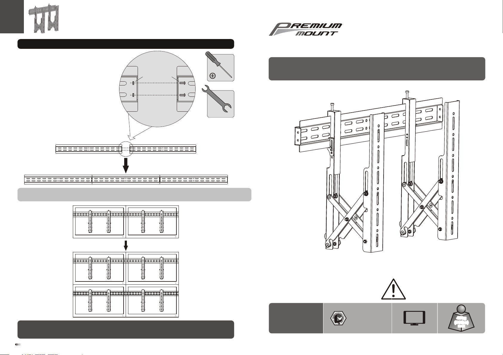
The Video wall ca n be as sem ble d by co nnecting w all p lat es wi th appropriat e scr ews a nd nu ts.
Calcu lat e the m oun ts and connecto r kit s nee ded f or your multi-s cre en in sta llation.
730 0 Bolsa Av e., We stm inst er, CA 92 683 -
Pre mium Mo unt Inc
Pho ne: 714 -766- 6303
Folding Video Wall Mount
INSTALLATION INSTRUCTIONS
Maint ena nce
• Check t hat t he br ack et is s ecure and sa fe to u se at r egu lar intervals (at l eas t eve ry three months ).
• Pleas e con tac t you r dealer if you hav e any q ues tio ns.
7
WBL S
400x2 00/ 300 x30 0
400x4 00/ 600 x40 0
CA UTI ON : DO NOT EXCE ED MA XIMUM
LIS TED W EIG HT CAPA CIT Y. SER IOU S
INJURY OR P ROP ERTY DAMA GE MAY
OCCUR!
60"
MAX
45kg
(99lbs)
MAX
ISSUED: NOV. 2012
Page 2
NOTE: Rea d the entire instr uction manual be fore you st art ins tallati on and as sembly.
WARNING
• Do not begin the installation until you have read and understood the instructions
and warnings contained in this installation sheet. If you have any question
regarding any of the instruction or warning, please contact your local distributor.
• This mounting bracket was designed to be installed and utilized ONLY as
specified in this manual. Improper installation of this product may cause damage
or serious injury.
• This product should only be installed by someone of good mechanical ability,
with basic building experience and fully understanding of this manual.
• Make sure that the supporting surface will safely support the combined load of
the equipment and all attached hardware and components.
• Always use assistant or mechanical lifting equipment to safely lift and position
equipment.
• Tighten screws firmly, but do not over tighten. Over tightening can damage the
items, greatly reducing their holding power.
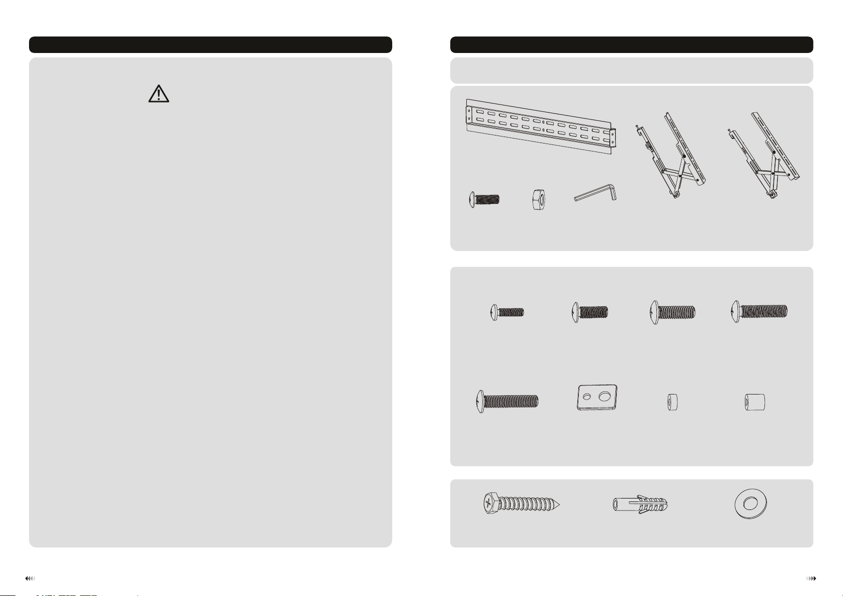
Component Checklist
IMPORTANT: Ensure t hat y ou ha ve re ceived al l par ts ac cor ding to the c omp one nt ch ecklist p rio r to in sta lling. If
any p art s are m iss ing or faulty, te lep hone your l oca l dis tri butor for a r epl ace men t.
wall pl ate A(x1)
Package M
M5x14 ( x4)
M-A
F
M6x14 ( x4)
M-B
left ad apt er br ack et B(x1)
M8x20 ( x4)
M-C
right a dap ter b rac ket C(x1)M5x14 ( x2)DM5 nut (x 2)EAllen k ey (x 1)
M6x30 ( x4)
M-D
• This product is intended for indoor use only. Using this product outdoors could
lead to product failure and personal injury.
1
M8x30 ( x4)
Package W
M-E
ST6.3 x55 ( x6)
W-A
washe r
(x4)
M-F
concr ete a nch or (x 6)
small s pac er (x 8)
M-G
W-B
big spa cer ( x4)
M-H
D6 wash er (x 6)
W-C
2
Page 3

1. Mount on Solid Brick and Concrete Block
60mm
60mm
60mm
(2.4")
(2.4")
2.4"( )
ø 10mm
(ø 3/8")
2. Install Adapter Brackets
W-B
1
Mark th e
exact l oca tio n of
mount ing h ole s
W-C
W-A
√
2
Drill pilot holes
X X
Screw the wall
plate onto
the wall
Top of disp lay
Adapt er br ack ets s hould be pulled o ut to t he ex ten ded position in o rde r to in sta ll screws throu gh
prope r hol es.
2-1 For Flat Back Screen
TV
TV
TV
M-A/M -B/ M-C
WARNING
• When insta lling wall mounts on cinder block, verify the actual concrete thickness is at least
1-3/8" (35 mm) for using the concret e anchors. Do not drill into mortar joints! Be sure to
mount in a soli d part of the block, generally 1" (25mm) minimum from the side of the block.
It is suggested electric drill on slow setting be used to drill the hole instead of a hammer drill
to avoid breaking out the back of the hole when entering a void or cavity.
• Installers must veri fy that the sup porting su rface will safely support the combi ned load of the
equipment and all attached hardware and components.
3
M-F
4
Page 4

2-2. For Bump-out or Rece ssed Back Screen
TV
TV
M-F
TV
M-F
M-D/M -EM-C M-C/M -D/ M-E
M-F
M-D/M -E
or or or
M-G
Note: C hoo se ap pro priate screws , was her s and s pacers (if nece ssa ry) a cco rdi ng to the type o f scr een .
M-G
M-G
M-H
M-H
· Posit ion t he ad apt er brackets as cl ose a s pos sib le to the center of t he di spl ay.
· Screw t he ad apt er br ackets onto the d isp lay.
Tig hten all screws b ut do n ot ov er ti ghten.
3. Hang Display onto the Wall Plate
Use the padlock to prevent
displa y from bein g stolen.
(The pad lock is not included )
M-F
M-G
4. Level Adjustment
wall wall
safet y cla mp
Hang top hook of a dapter br ack ets onto th e top wall pl ate rail. Push the sa fety clam ps up ward and ti ghten
screws t o secure th e bracket .
F
Slight a djustme nt allowed
after di splay ins tallation by
loosen ing or tigh tening
screws w ith an Allen key
suppli ed.
65
 Loading...