

Page 1
730 0 Bolsa Av e., We stm inst er, CA 92 683 -
Pre mium Mo unt Inc
Pho ne: 714 -766- 6303
LCD Wall Mount
INSTALLATION INSTRUCTIONS
Secur e you r dis pla y to the mount by tig hte nin g scr ews(just remo ved ).
Maint ena nce
• Check t hat t he br ack et is s ecure and sa fe to u se at r egu lar intervals (at l eas t eve ry three months ).
• Pleas e con tac t you r dealer if you hav e any q ues tio ns.
7
WB- 5
50x50
75x75
100x1 00
CA UTI ON : DO NOT EXCE ED MAXIMU M
LIS TED W EIG HT CAPA CITY. SE RIO US
INJ URY OR PROP ERTY DAMA GE MAY
OCC UR!
23"
MAX
30kg
(66lbs)
MAX
ISSUED: JAN. 2013
Page 2
NOTE: Rea d the entire instr uction manual be fore you st art ins tallati on and as sembly.
WARNING
• Do not begin the installation until you have read and understood the instructions
and warnings contained in this installation sheet. If you have any questions
regarding any of the instruction or warning, please contact your local distributor.
• This mounting bracket was designed to be installed and utilized ONLY as
specified in this manual. Improper installation of this product may cause damage
or serious injury.
• This product should only be installed by someone of good mechanical ability,
with basic building experiences and fully understanding of this manual.
Component Checklist
IMPORTANT: Ensure t hat y ou ha ve re ceived al l par ts ac cor ding to the c omp one nt ch eck list prio r to in sta lli ng. If
any p art s are m iss ing or faulty, te lep hone your l oca l dis tri butor for a r epl ace men t.
• Make sure that the supporting surface will safely support the combined load of
the equipment and all attached hardware and components.
• If mounting to wood wall studs, make sure that mounting screws are anchored
into the center of the studs. Use of a stud finder is highly recommended.
• Always use an assistant or mechanical lifting equipment to safely lift and position
equipment.
• Tighten screws firmly, but do not over tighten. Over tightening can damage the
items, greatly reducing their holding power.
• This product intended for indoor use only. Using this product outdoors could
lead to product failure and personal injury.
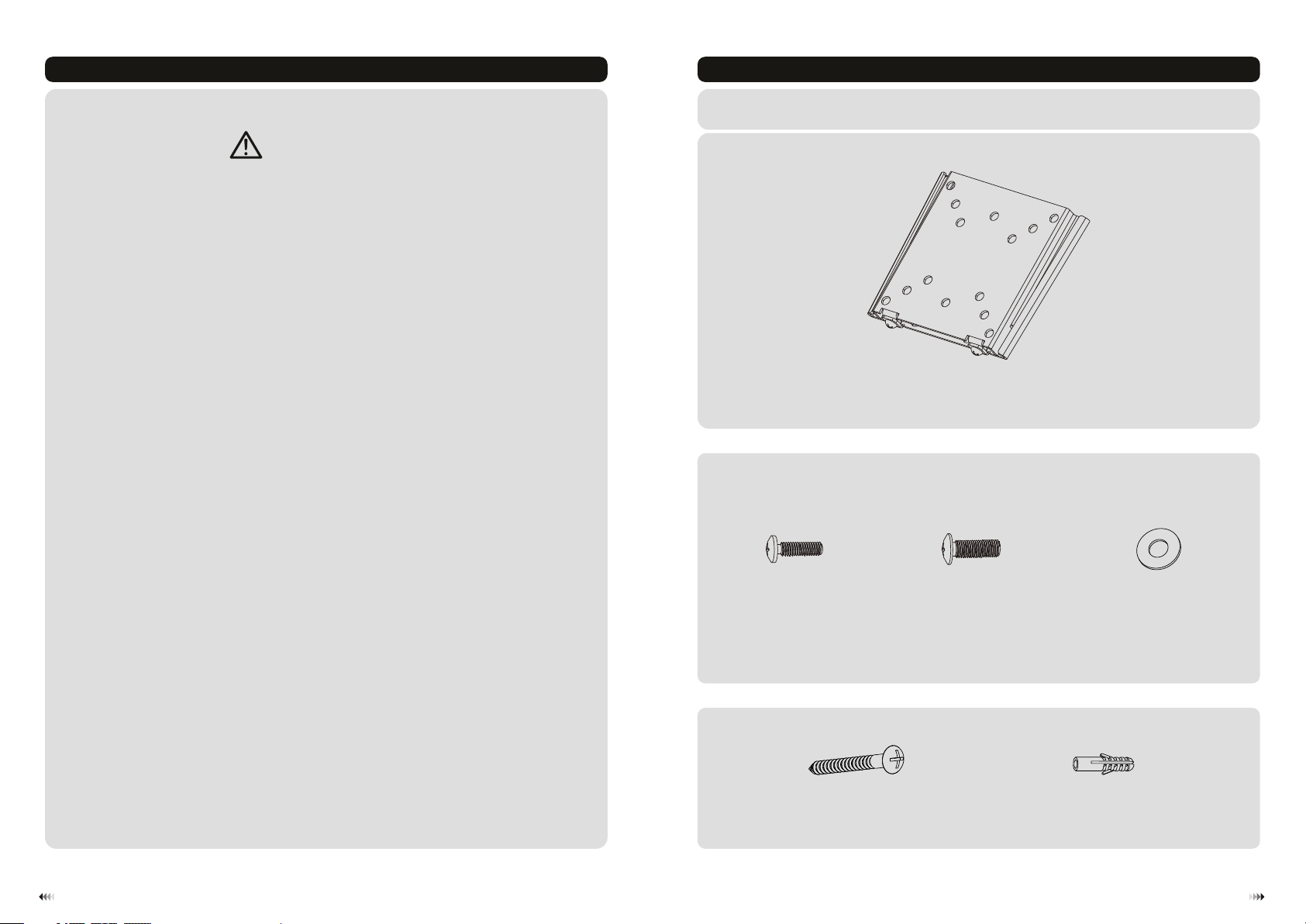
Package M
Package W
M4x14
M-A
(x4)
5 5 0 2
W-A
M5x14 ( x4)
M-B
D5 (x4)washe r
concr ete a nch or
W-B
M-C
(x2)ST . x5 (x )
21
Page 3

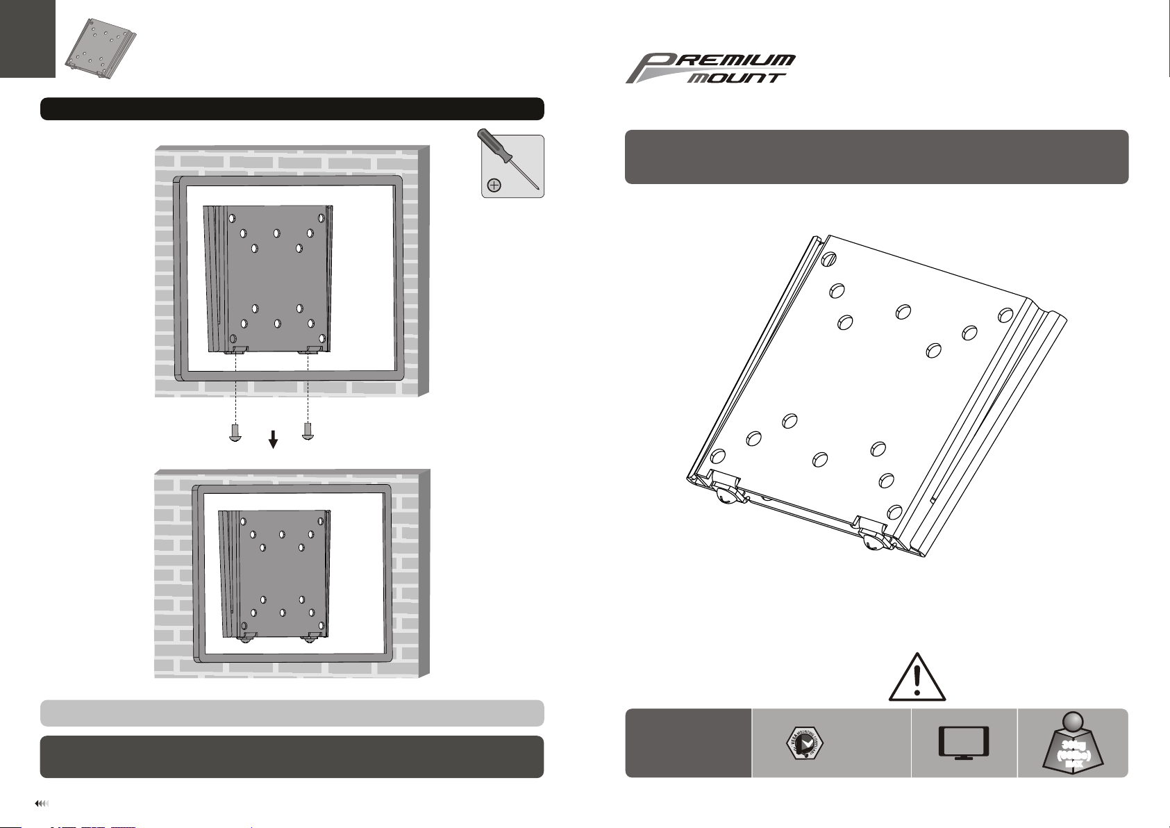
1. Separate VESA Plate
2a. Mount on Wood Stud Wall
Use too l to lo ose n the b ottom
screw s in or der t o sep arate the
VESA pla te fr om th e wal l mount.
55mm
55mm
50mm
(2.2")
2.2"( )
(2" )
ø 4mm
(ø 5/32")
2b. Mount on Solid Brick and Concrete Block
60mm
60mm
60mm
(2.4")
2.4"( )
(2.4")
Mark th e exa ct
locat ion o f
mount ing h ole s
ø 8mm
(ø 5/16" )
1
2
Drill pilot holes
1
Find an d mar k the
W-A
2
exact l oca tio n of
mount ing h ole s
3
Drill pilot holes
√
X X
Screw the wall
mount onto
the wall
WARNING
• Make sure that mounting screws are anchored into the center of the studs. Use of a stud finder
is highly recommended.
• Installers are responsible to provide hardware for other types of mounting situations.
• Installers must verify that the supporting surface will safely support the combined load of the
equipment and all attached hardware and components.
W-B
√
W-A
X X
Screw the wall
mount onto
the wall
WARNING
• When installing wall mounts on cinder block, verify the actual concrete thickness is at least
1-3/8" (35 mm) for using the concret e anchors. Do not drill into mortar joints! Be sure to
mount in a soli d part of the block, generally 1" (25mm) minimum from the side of the block.
It is suggested electric drill on slow setting is used to drill the hole instead of a hammer drill
to avoid breaking out the back of the hole when entering a void or cavity.
• Installers must veri fy that the sup porting su rface will safely support the combined load of the
equipment and all attached hardware and components.
3
4
Page 4

4. Install the Display3. Install the VESA Plate
TV
TV
TV
M-A
M-B
M-C
Tig hten all screws b ut do n ot ov er ti ghten.
5
Lift th e dis pla y, ali gni ng ho les i n VESA plate wi th mo unt h ole s in wa ll plate.
6
 Loading...