

Page 1
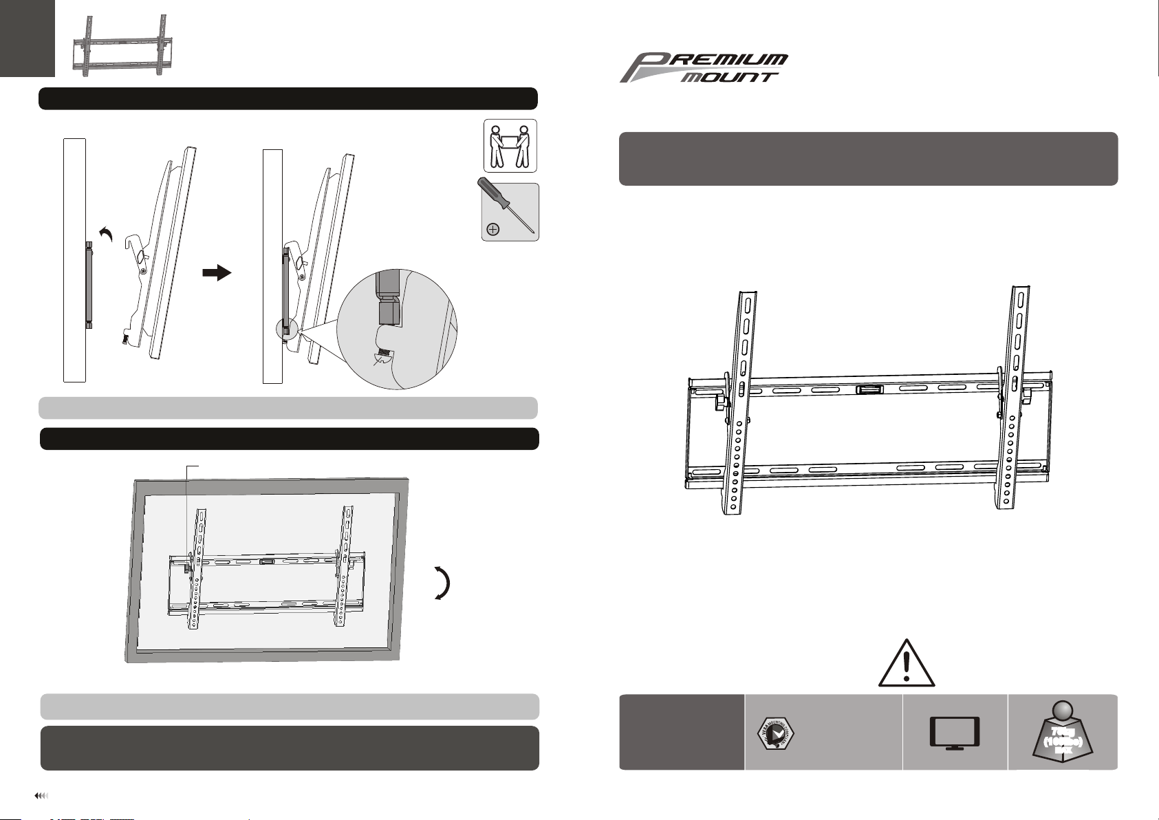
3. Hang Display onto the Wall Plate
wall
Tighten bottom bolts to secur e display brackets to the wall plat e.
wall
4. Adjustment
Tilt adj us ting knob
Bolt
730 0 Bolsa Av e. , Wes tm ins ter, CA 926 83 -
Pre mium Mo unt Inc
Pho ne: 714 -766- 6303
Tilting Wall Mount
INSTALLATION INSTRUCTIONS
0°
-1 0°
Loo se the adju st ing knobs t o tilt de si red angle t hen tight en them.
Maintenance
• Check that the bra cket is secure and safe to use at regul ar intervals(at least eve ry thr ee months).
• Please contact y our dealer if you have any ques tion s.
7
WB-4780
400x40 0/ 60 0x 40 0
800x40 0/ 80 0x 60 0
CA UT IO N : DO N OT EX CE ED M AX IMU M
LIS TE D WE IG HT CAPAC IT Y. SERIOU S
INJURY OR PR OP ERTY DA MA GE MAY
OCCUR !
70"
MAX
75kg
(165lbs)
MAX
ISSUED: OCT.2012
Page 2
NOTE : Rea d the ent ire i nstru cti on manu al be fore yo u sta rt inst all ation a nd as sembl y.
WARNING
• Do not begin the installation until you have read and understood the instructions
and warnings contained in this installation sheet. If you have any question
regarding any of the instruction or warning, please contact your local distributor.
• This mounting bracket was designed to be installed and utilized ONLY as
specified in this manual. Improper installation of this product may cause damage
or serious injury.
• This product should only be installed by someone of good mechanical ability,
with basic building experience and fully understanding of this manual.
• Make sure that the supporting surface will safely support the combined load of
the equipment and all attached hardware and components.
• If mounting to wood wall studs, make sure that mounting screws are anchored
into the center of the studs. The use of a stud finder is highly recommended.
• Always use assistant or mechanical lifting equipment to safely lift and position
equipment.
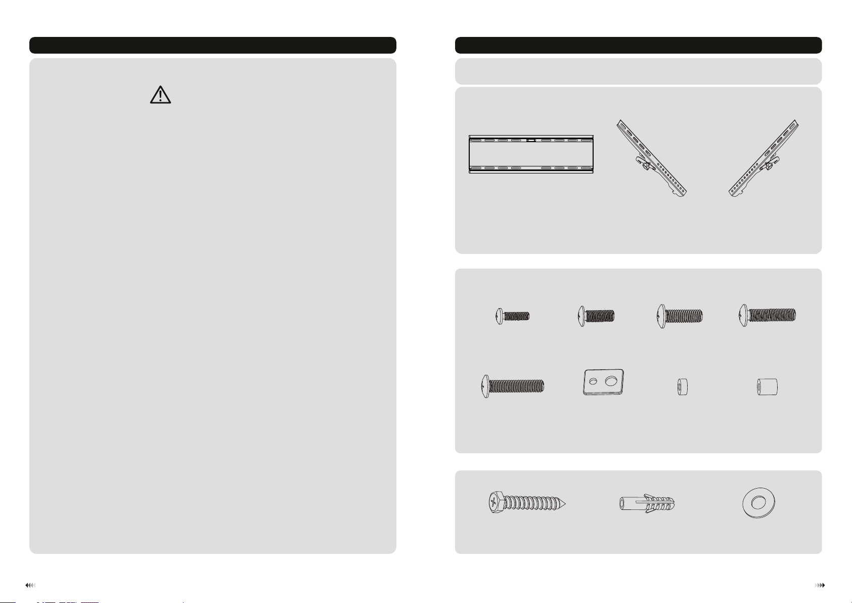
Component Checklist
IMPO RTANT: Ensure t ha t yo u ha ve r ec eived a ll p ar ts a cc or ding to the c om po ne nt c hecklis t pr io r to i ns talling . If
any p ar ts a re m is si ng or fau lt y, te le phone y ou r lo ca l di st ribut or f or a r ep la ce ment.
right (x1)adapt er b ra ck et
C
M6x30 (x 4)
M-D
Pack age M
M5x14 (x 4)
wall pla te
A
M-A
(x1)
M6x14 (x 4)
M-B
left (x1)adapte r br ac ke t
B
M8x20 (x 4)
M-C
• Tighten screws firmly, but do not over tighten. Over tightening can damage the
items, greatly reducing their holding power.
• This product is intended for indoor use only. Using this product outdoors could
lead to product failure and personal injury.
1
M8x30 (x 4)
Pack age W
M-E
ST6.3x 55 ( x6 )
W-A
washer
(x4)
M-F
concre te a nc ho r (x 6)
small sp ac er ( x8 )
M-G
W-B
big spac er ( x4 )
M-H
D6 washe r (x 6)
W-C
2
Page 3

1a. Mount on Wood Stud Wall
55mm
55mm
55mm
(2.2")
(2.2" )
2.2"( )
ø 4.5mm
(ø 3/16")
1b. Mount on Solid Brick and Concrete Block
60mm
60mm
60mm
(2.4")
(2.4")
2.4"( )
ø 10mm
(ø 3/8" )
W-C
W-A
Find and m ar k th e
exact lo ca ti on o f
mounti ng h ol es
√
1
2
3
Drill pilot holes
X X
Screw the wall
plate onto
the wall
W-B
W-C
W-A
Mark the e xa ct
locati on o f
mounti ng h ol es
√
1
2
Drill pilot holes
X X
Screw the wall
plate onto
the wall
WARNING
• Make sure that mounting screws are anchored into the center of the studs. The use of a stud
finder is highly recommended.
• Installers are responsible to provide hardware for other types of mounting situations.
• Installers must verify that the supporting surface will safely support the combined load of the
equipment and all attached hardware and components.
3
WARNING
• When installing wall mounts on cinder block, verify the actual concrete thickness is at least
1-3/8" (35mm) for using the concrete anchors. Do not drill into mortar joints! Be sure to
mount in a solid part of the block, generally 1" (25mm) minimum from the side of the block.
It is suggested electric drill on slow setting be used to drill the hole instead of a hammer drill
to avoid breaking out the back of the hole when entering a void or cavity.
• Installers must verify that the supporting surface will safely support the combined load of th e
equipment and all attached hardware and components.
4
Page 4

2. Install Adapter Brackets
2-2 For Recessed Back Screen or to Access A/V Inputs
2-1 For Flat Back Screen
TV
TV
TV
TV
Top of displ ay
TV
TV
M-A
M-B
M-C
M-F
M-C
M-G
M-C
M-D
M-F
or or or
M-E
M-G
M-G
M-F
M-D
M-E
M-H
M-F
M-D
M-E
M-G
M-H
M-F
Note: Ch oo se a pp ro pr ia te screws, wa sh er s an d sp ac er s (if necessary ) ac co rd in g to t he t ype of screen .
· Positi on t he a da pt er b ra ckets as close as p os si bl e to t he c enter of the disp la y.
· Screw th e ad ap te r br ac ke ts onto the dis pl ay.
Tig hten all screws b ut d o no t ov er t ig ht en.
65
 Loading...