

Page 1
730 0 Bolsa Av e., We stm inst er, CA 92 683 -
Pre mium Mo unt Inc
Pho ne: 714 -766- 6303
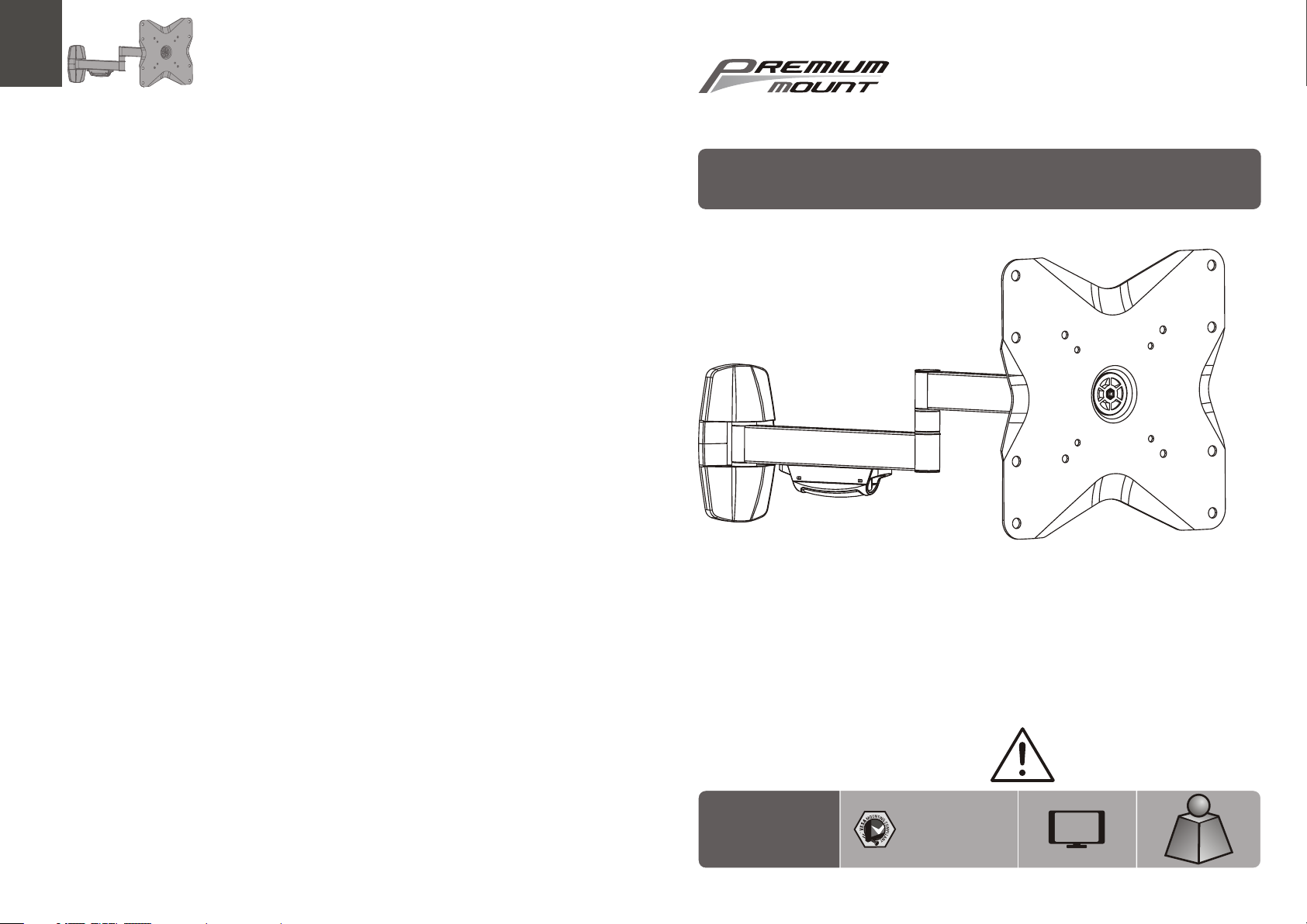
Full-motion Wall Mount
INSTALLATION INSTRUCTIONS
WB- 31
75x75 /10 0x1 00
200x1 00/ 200 x20 0
CA UTI ON : DO NOT EXCE ED MA XIMUM
LIS TED W EIG HT CAPA CIT Y. SE RIOU S
INJURY OR P ROP ERTY DAMA GE MAY
OCCUR!
37"
MAX
20kg
20kg
20kg
(44lbs)
(44lbs)
(44lbs)
MAX
MAX
MAX
ISSUED: OCT. 2012
Page 2
NOTE: Rea d the entire instr uction manual be fore you st art ins tallati on and as sembly.
WARNING
• Do not begin the installation until you have read and understood the instructions
and warnings contained in this installation sheet. If you have any question
regarding any of the instruction or warning, please contact your local distributor.
• This mounting bracket was designed to be installed and utilized ONLY as
specified in this manual. Improper installation of this product may cause damage
or serious injury.
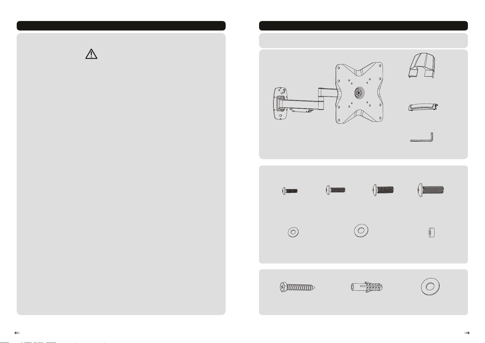
Component Checklist
IMPORTANT: En sure that y ou ha ve re cei ved all par ts ac cor din g to the comp one nt ch eck list prio r to in sta lli ng. I f
any p art s are m iss ing or faulty, te lep hone your l oca l dis tri butor for a r epl ace men t.
decor ati ve co ver ( x2)
B
cable c ove r (x1 )
C
• This product should only be installed by someone of good mechanical ability,
with basic building experience and fully understanding of this manual.
• Make sure that the supporting surface will safely support the combined load of
the equipment and all attached hardware and components.
• If mounting to wood wall studs, make sure that mounting screws are anchored
into the center of the studs. The use of a stud finder is highly recommended.
• Always use assistant or mechanical lifting equipment to safely lift and position
equipment.
• Tighten screws firmly, but do not over tighten. Over tightening can damage the
items, greatly reducing their holding power.
• This product is intended for indoor use only. Using this product outdoors could
lead to product failure and personal injury.
Package M
M4x14 ( x4)
D5 wash er (x 4)
Package W
ST6.3 x55 ( x3)
M-A
artic ula ted a rm as sembly
M-E
W-A
A
M5x14 ( x4)
M-B
M6x14 ( x4)
M-C
D8 wash er (x 4)
M-F
concr ete a nch or (x 3)
W-B
3mm Allen key (x1)
D
M8x20 ( x4)
M-D
small s pac er (x 8)
M-G
D6 wash er (x 3)
W-C
21
Page 3

1. Remove VESA Plate
2b. Mount on Solid Brick and Concrete Block
60mm
60mm
60mm
(2.4")
2.4"( )
(2.4")
ø 10mm
(ø 3/8")
2a. Mount on Wood Stud Wall
W-C
W-A
55mm
55mm
55mm
2.2"( )
(2.2")
(2.2")
ø 4.5mm
(ø 3/16")
1
Fin d and ma rk the exact
loc ation of mou nting holes
2
√
3
Drill pilot holes
X X
W-B
W-C
W-A
1
Mar k the ex act
loc ation of
mou nting
hol es
√
2
Drill pilot holes
X X
Screw the wall
mount onto
the wall
With arrow head pointing up
WARNING
• Make sure that mounting screws are anchored into the center of the studs. The use of a stud
finder is highly recommended.
• Installers are responsible to provide hardware for other types of mounting situations.
• Installers must verify that the supporting surface will safely support the combined load of the
equipment and all attached hardware and components.
3
Screw the wall
mount onto
the wall
With arrow head pointing up
WARNING
• When installing wall mounts on cinder block, verify the actual concrete thickness is at least
1-3/8" (35 mm) for using the concret e anchors. Do not drill into mortar joints! Be sure to
mount in a soli d part of the block, generally 1" (25mm) minimum from the side of the block.
It is suggested electric drill on slow setting be used to drill the hole instead of a hammer drill
to avoid breaking out the back of the hole when entering a void or cavity.
• Installers must veri fy that the sup porting su rface will safely support the combined load of the
equipment and all attached hardware and components.
4
Page 4

3. Install Decorative Covers
TV
TV
TV
TV
M-A
M-B
M-C
M-D
M-E
M-F
or
4. Install VESA Plate
Top of display
M-G
M-G
Note: C hoo se ap pro priate screws , was her s and s pacers (if nece ssa ry) a cco rding to the type o f scr een .
•Scre w VES A plat e ont o the display.
Tig hten all screws b ut do n ot ov er ti ghten.
M-F
M-D
M-G
M-F
M-D
65
Page 5

5. Hook the Display onto the Wall Mount
6. Cable Management
wall
D
It is nec ess ary t o sli ght ly loosen
or tigh ten t he ad jus tment screw
using a n Alle n key.
wall
Inser t VES A plat e int o mount rail. Tigh ten s cre w (th at is previousl y rem ove d) wi th a proper screw dri ver.
• Connect cables to your display and route along the arms.
• Fit the cable cover into rail to hold the cables.
Note: L eav e sla ck in c ables for canti lev er ar m mov ement.
87
Page 6

7. Adjustment
180°
180°
+15°
360°360°360°
-15°
Adjus t to de sir ed lo cation or tilt.
Maint ena nce
• Check t hat t he br ack et is s ecure and sa fe to u se at r egu lar intervals (at l eas t eve ry three months ).
• Pleas e con tac t you r dealer if you hav e any q ues tio ns.
109
 Loading...