

Page 1
www.orioncontrols.com
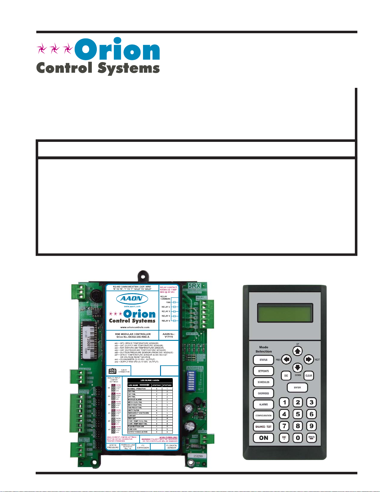
Modular Service Tool SD
Quick Start Guide
Requires Modular Service Tool SD Code: SS1063
VCC-X Controller Code: SS1062 Version 2.0 and up
VCB-X Controller Code: SS1051 Version 2.0 and up
VCM-X Controller Code: SS1026
VCM-X E-BUS Controller Codes: SS1030, SS1032, SS1033, SS1034
RNE Controller Code: SS1045
SA E-BUS Controller Code: Y200921
VCM Controller Code: SS1016
VAV/CAV Controller Code: SS1003 and MUA II Controller Code: SS1004
VAV/Zone Controller Codes: SS1001, SS1005, SS1025
MiniLink PD Code: SS0040
Page 2
IMPORTANT NOTICE
This Quick Start guide provides instructions for operating the Modular
Service Tool SD.
The Modular Service Tool SD Operator Interface Guide for each controller
is available for download from our website at orioncontrols.com or if you
have the Modular Service Tool SD Card available, the technical guides can
also be printed from the SD card.
VCC-X Controller - OR-VCCXOISD-TGD
VCM-X & VCM-X E-BUS Controllers - OR-VCMXRNEOISD-TGD
RNE Controller - OR-VCMXRNEOISD-TGD
SA E-BUS Controller - AA-SAOISD-TGD
VCB-X Controller - OR-VCBXOISD-TGD
VCM Controller - OR-VCMOISD-TGD
VAV/CAV and MUA II Controllers - OR-VAVCAVMUAOISD-TGD
SD CARD UPDATING INSTRUCTIONS
Your Modular Service Tool comes with an SD memory card that contains
the software to communicate to the various controllers. This SD card can
be removed and easily updated through a computer by downloading
updates, as they become available, from our website to your computer.
In order to perform any updates, your computer needs an SD card drive or
you will need to purchase an SD card adapter.
Download instructions are found in Appendix B of this manual.
www.orioncontrols.com
WattMaster Controls, Inc.
8500 NW River Park Drive · Parkville, MO 64152
Toll Free Phone: 866-918-1100
PH: (816) 505-1100 · FAX: (816) 505-1101
E-mail: mail@wattmaster.com
Visit our website at www.orioncontrols.com
AAON® is a registered trademark of AAON, Inc., Tulsa, OK.
WattMaster Controls, Inc. assumes no responsibility for errors
or omissions.
This document is subject to change without notice.
Form: OR-QSOISD-TGD-01F
Copyright May 2015 WattMaster Controls, Inc.
Page 3

TABLE OF CONTENTS
INTRODUCTION ................................................................................................................4
Modular Service Tool ...............................................................................................................................4
SYSTEM CONNECTION .....................................................................................................5
Modular Service Tool ...............................................................................................................................5
INTERFACE OVERVIEW .....................................................................................................6
Display Screens and Data Entry Keys .....................................................................................................6
Mode Selection Buttons ...........................................................................................................................6
INITIALIZA TION ................................................................................................................ 7
Initialization & Setting the Time & Date ...................................................................................................7
Setting the Operating Mode & Energy Timer ...........................................................................................8
Alarm & Override Search .........................................................................................................................9
Schedules & Holidays ............................................................................................................................10
Schedule Override ................................................................................................................................. 11
TROUBLESHOOTING .......................................................................................................12
Outputs Force ........................................................................................................................................ 12
APPENDIX A - SAVING, LOADING, AND COPYING SETPOINTS .....................................14
APPENDIX B - UPDATING THE SD MEMORY CARD ........................................................16
APPENDIX C - UPDATING CONTROLLERS & E-BUS MODULE SOFTWARE .................... 17
Modular Service Tool SD
3
Page 4
SYSTEM CONNECTION
Modular Service Tool SD
Zone
Zone
Modular Service Tool SD
The OE391-12 Modular Service Tool is a system operator interface that
provides a direct link to enable the system operator to view the status,
confi gure, and adjust the setpoints of the VCM-X, VCM-X E-BUS,
SA E-BUS, RNE, VCB-X, VCM, VAV/CAV, MUA II or VAV/Zone
Controller on the control system communications loop.
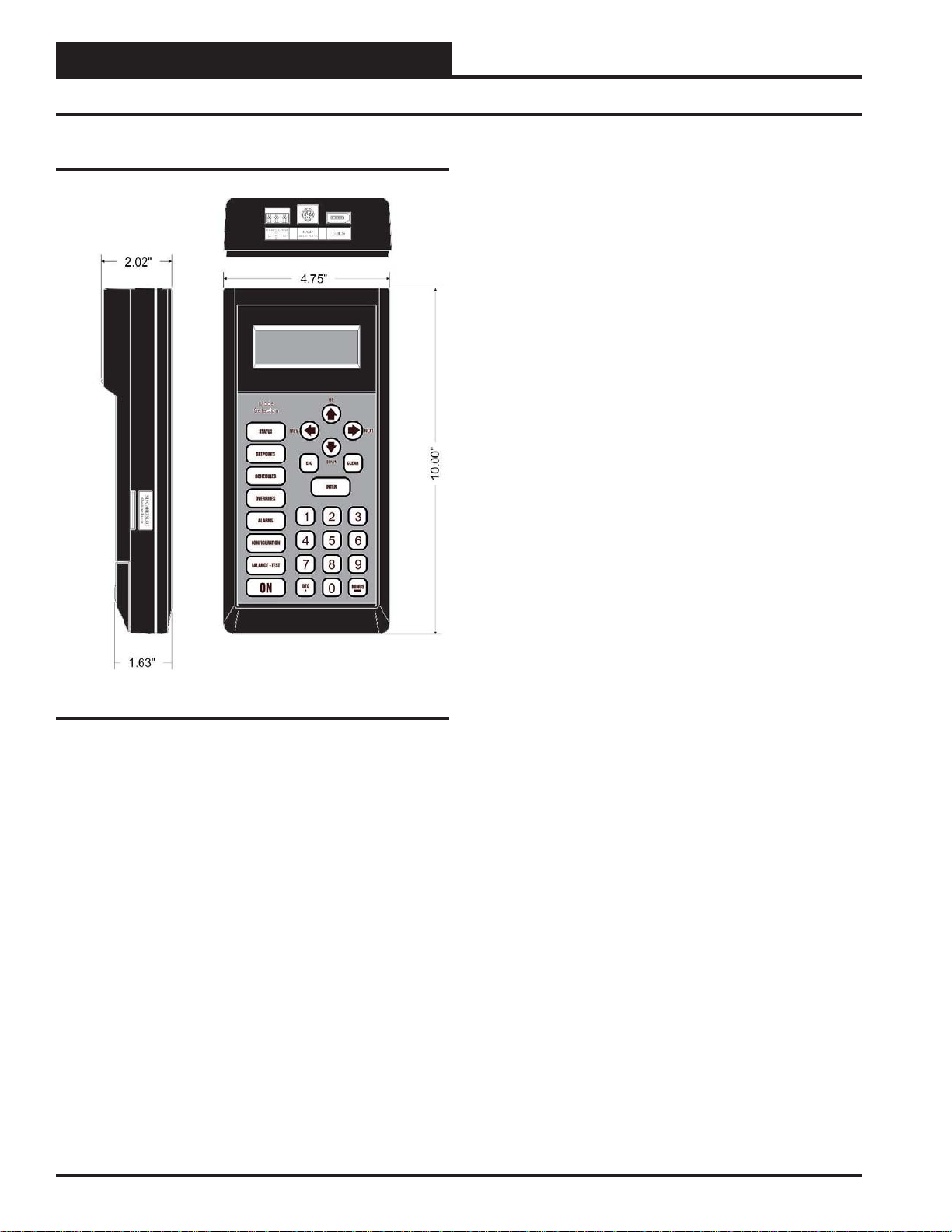
The Modular Service Tool is housed in an attractive black plastic
enclosure. The display area is covered with a clear plastic bezel for
protection of the display screen. The Modular Service Tool has a
4-line-by-20-character display panel with adjustable contrast control
and a 27-key membrane keypad for data selection and entry. All keypad
operations are simple and straight forward, utilizing non-cryptic plain
English language messages. Menu-driven programming allows for
easy setup and operation without the need for specialized training. The
Modular Service T ool is supplied with a programmable 4 Gigabyte SD
memory card, with (4) AA 1.5 V batteries, a wall mount a DC power
supply, a mini-Din communication cable, and an E-BUS communication
cable. The mini-Din cable allows you to connect the Modular Service
Tool to any Orion controller which has a mini-Din connector socket for
programming, monitoring, and troubleshooting purposes.
The Modular Service Tool is also equipped with an EBC E-BUS port
and an RS-485 three conductor terminal block port. The E-BUS port and
included E-BUS cable are used for updating E-BUS Module software
(described in Appendix C, page 17). The RS-485 port is used for hard-
wiring to older controllers that do not have a mini-DIN connector socket.
The Modular Service Tool is designed to be hand-carried. Its rugged
plastic housing provides superior protection for the electronic components housed inside. The Modular Service Tool is a top-quality service
tool that will stand up to the demands of the typical job site environment
for many years.
Figure 1: Modular Service Tool Dimensions
4
Modular Service Tool SD
Page 5
SYSTEM CONNECTION
Modular Service Tool SD
Modular Service Tool SD
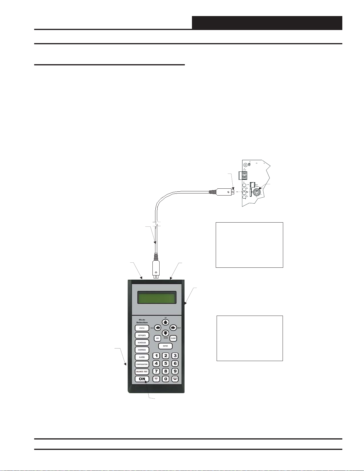
Whether you have a Stand Alone, Interconnected, or Networked Orion
Controls System, the Modular Service Tool always connects to the
controller or a VAV/Zone Controller via a prefabricated cable that is
supplied with the service tool. The Modular Service Tool cable is terminated on both ends with a mini-DIN connector. Attach one end to the
Modular Service Tool and the other end to the mini-DIN connector on
the controller. If this is an Interconnected System, all controllers that are
interconnected with communications cable can be programmed from any
controller on the loop. If this is a Networked System, all controllers on
the entire Networked System can be programmed from one controller.
Male DIN Connector
Connector Cable
RS-485
Port
Be sure that the Modular Service Tool’s SD memory card is inserted
correctly and that the Modular Service T ool has fresh batteries installed
or that it is connected to a power source using the supplied power pack
before attempting any programming of the controller. See Figur e 2 for
connection details.
Female DIN
Connector
Typical Controller Board
EBC
E-BUS
Port
The Modular Service Tool Can Be
Connected To
Or VAV/Zone Controller By
Plugging One End Of The
Supplied Cable Into the
Modular Service Tool DIN
Connector And The Other End
Into The DIN Connector On The
Controllers.
A Unit Controller
SD Memory Card
Figure 2: Modular Service Tool SD
Modular Service Tool SD
Power On Button
Modular Service Tool SD
Be Sure The Modular Service
Tool Is Connected ToThe
Supplied Power Pack Or Has
Fresh Batteries Installed Before
Attempting Programming Of The
Controller. Be Sure The Power Is
Turned Off On The Modular
Service ToolBefore Connecting
The Cable To The Controller.
5
Page 6

INTERFACE OVERVIEW
Modular Service Tool Keys
Operator Interfaces
In order to confi gure and program the Orion System controllers, you
must have an Operator’s Interface or a personal computer with the Prism
2 computer front-end software installed. Three different Operator Interfaces are available for programming of the Orion Controls System—the
Modular Service Tool SD, the Modular System Manager (VCM-X and
VAV/Zone Controllers only), and/or the System Manager TS II. These
devices allow you to access the status and setpoints of the controllers on
your communications loop. This manual describes the Modular Service
Tool SD. If using the Modular System Manager or System Manager TS
II, please see the VCM-X / RNE Operator Interfaces Technical Guide
or the System Manager TS II Technical Guide. If using Prism 2, please
see the Prism 2 Technical Guide.
The Modular Service T ool allows you to view any input or output status
and change any setpoint to fi ne-tune the operations of the total system. All
keypad operations are simple and straightforward, utilizing non-cryptic
plain English messages.
Display Screens & Data Entry Keys
See the chart below for a list of the keypad descriptions and functions.
Keypad
Key Function
Description
NEXT
ESC
ENTER
Clear
Minus
DEC
Use this key to access the
Setup Screens.
Use this key to exit from screens or
from data entry or to return to the
Main Screen from any screen in the
system.
Use this key to enter a new value.
If a data entry mistake is made,
press this key to clear the data entry
fi eld and start over. This key also
turns off the power to the Service
Tool when on the
Main Screen
If a setpoint with a negative value
is required, press this key for the
minus sign.
Press this key when entering data
that requires a decimal point.
Use these keys to change values
in the Confi guration screens as
prompted.
Use these keys to step backward or
forward through the screens.
Mode Selection Buttons
The Modular Service Tool is provided with “Mode Selection Buttons.”
These buttons give you instant access to the specifi c mode desired without
having to scroll through several menu screens to get there.
Button
Description
STATUS
SETPOINTS
SCHEDULES
OVERRIDES
ALARMS
CONFIGURATION
BALANCE-TEST
Notes:
(1) The Modular Service T ool will only search the Over rides one loop at a time. Y ou must enter the Loop number
and the MiniLink PD unit ID (60).
Table 2: Button Descriptions
Mode Selection Buttons
Pressing this button takes you
directly to the controller
“Status” screens.
Pressing this button takes you
directly to the controller
“Setpoints” screens.
Pressing this button takes you
directly to the controller
“Schedules” screens.
Pressing this button takes you
directly to the controller “Overrides” screen. See the “Override
Button” section on page 9 for a
description of this function.
See Note 1 below.
Pressing this button takes you
directly to the controller
“Alarms” screen. See the “Alarms
Button” section on page 9 for a
description of this function.
Pressing this button takes you
directly to the controller
“Confi guration” screens.
Pressing this button takes you
directly to the controller
“Balance-Test” screens.
Table 1: Keypad Descriptions
6
Modular Service Tool SD
Page 7

INITIALIZATION
Initialization & Setting the Time & Date
Modular Service Tool Initialization
Modular Service Tool Initialization Screen and
Setup Screens
After connecting the Service Tool to the controller with the supplied
cable, press <ON>. The Initialization Screen will appear followed by
the Setup Screens as shown below. If there is no SD card installed, the
second screen will display, “No SD Card Connected! Powering Down!”
Initializing
Service Tool vX.XX
WattMaster Controls
1) Set Time & Date
2) Communications
NEXT) More Options
ESC) Exit Menu
3) Energy Saving
4) Update Software
NEXT) More Options
ESC) Exit Menu
Although the times are displayed on the Main Screen in a standard 12hour format, you must program them using the 24-hour military format.
If you confi gured the Unit Controller to use its own Internal Schedules,
the Occupied/Unoccupied modes are calculated on the basis of the current real time clock reading.
The two screens that follow will appear. To scroll through the fi elds,
press
<> or <ENTER>. In order to save a new value, you must press
<ENTER>.
Program Time/Date
Day (Sunday=0): X
Enter Hr. (0-23): XX
Enter Minutes : XX
Day - Enter the Day of the Week (0 to 6)
Sunday = 0
Hours (Hr) - Enter Hours in 24-Hour Military Format
(17 = 5:00 PM)
Minutes - Enter the Minutes
(0 to 59)
Programming the Date
NOTE: Once you press <ESC> while at the Setup Screens shown
above, you can access them again by pressing <NEXT>
or cycling power.
Setting The Time & Date
The Modular Service Tool is equipped with a real time clock chip
allowing it to maintain the correct time. Once you have programmed
the correct time and date, the information is broadcast globally to all
controllers on the entire system.
NOTE: If you are in a time zone that has daylight savings, you
will need to manually adjust the time twice a year.
Programming the Time
From the Setup Screen shown below, press <1> on your keypad to access the Set Time & Date Screens. (You may have to press <NEXT>
to access this screen).
1) Set Time & Date
2) Communications
NEXT) More Options
ESC) Exit Menu
To scroll through the fi elds, press <> or <ENTER>. In order to save
a new value, you must press <ENTER>.
Program Time/Date
Month (1-12): XX
Day (1-31): XX
Year (0-99): XX
Month - Enter the Month (1 to 12)
Day - Enter the Day of the Month (1 to 31)
Year - Enter the current Year (0 to 99)
When you have fi nished programming the time and date, press <ESC>
to return to the Setup Screen shown below.
1) Set Time & Date
2) Communications
NEXT) More Options
ESC) Exit Menu
Modular Service Tool SD
7
Page 8

INITIALIZATION
Setting the Operating Mode and Energy Saving Timer
Setting the Operating Mode
The Operating Mode is displayed on the last line of the Main Screen
as shown below. The factory default setting for the Service Tool is LS
(Low Speed) Stand Alone Mode.
Service Tool SD vX.XX
Wednesday Operations
01/16/13 02:21 PM
LS Stand Alone *00*
If you are using this Service Tool on a communications loop and have
an installed MiniLink PD or CommLink, you will need to change the
setting to LS (Low Speed) Network Mode.
If you are using a VCC-X, VCB-X, or GPC-XP Controller that is set
for high speed, you will need to change the setting to HS (High Speed)
Stand Alone Mode or HS (High Speed) Network Mode.
If your display indicates a different mode than the one you need, press
<2> at the Setup Screen shown below . Y ou may have to press <NEXT>
to access this screen.
1) Set Time & Date
2) Communications
NEXT) More Options
ESC) Exit Menu
The Communications Screen will appear as shown below.
Setting the Energy Saving Timer
The Modular Service T ool has a built-in timer that can be programmed
to shut the Service T ool off after a specifi ed period of time if no buttons
are pressed. This is a very useful feature if you are powering the Service
Tool from the internal batteries.
To set the Ener gy Saving T imer, press
and
<3> at the second Setup Screen shown below. (You may have to
press <NEXT> to access these screens).
1) Set Time & Date
2) Communications
NEXT) More Options
ESC) Exit Menu
3) Energy Saving
4) Update Software
NEXT) More Options
ESC) Exit Menu
The Energy Saving Screen will appear as shown below:
Energy Saving
Automatic Power Down
Minutes: xx
Press ESC to Exit
<NEXT> at the fi rst Setup Scr een
Stand Alone Mode
Lo Speed Connection
Use Left/Right Arrow
To Change Selections
Press <> or <> if you need to change the mode of operation.
When you have made your selection, press <ENTER>. The following
screen will appear.
You Have Changed The
System Mode
Press Any Key To
Continue
Press any key to continue. The Setup Screen will appear as shown below:
1) Set Time & Date
2) Communications
NEXT) More Options
ESC) Exit Menu
Enter the number of minutes you want the Service Tool to stay active
before it automatically powers down and press <ENTER>. To cancel
the automatic power down, enter <99> and press <ENTER>. After
you have entered a number between 1 and 99 minutes, press <ESC>
to exit the screen. The Setup Screen will appear again.
Updating Software
The Modular Service T ool SD has the capability to update the software
for certain Controllers and E-BUS Modules using the appropriate
cable(s) and a computer with internet access.
The instructions for Updating Software - Option 4 on the second Setup
Screen shown below are found in Appendix C, page 17.
3) Energy Saving
4) Update Software
NEXT) More Options
ESC) Exit Menu
8
Modular Service Tool SD
Page 9

INITIALIZATION
Alarm and Override Search
Modular Service Tool Alarm Search
NOTE: When you press the <ALARMS> button on the Modular
Service T ool, it will search only the unit ID that you have
entered; therefore, you must search each unit individually
to access all alarms for that controller.
To search for alarms, press < ALARMS>while on any screen but the
Setup Screen(s). The Unit Selection Screen will be displayed.
Unit Selection
Enter Unit ID#
Selected ID#: XXXX
*00*
Enter the Unit ID of the controller the Service T ool is connected to and
press <ENTER>. Once communication is established, *00* at the bot-
tom right of the screen will go away. Then
NOTE: If the *00* remains, it indicates a communication failure
to the controller.
One of the following screens will appear:
press <>.
Modular Service Tool Override Search
When a space sensor with override option is used with any VAV/Zone
or Unit Controller, the Modular Service Tool can determine and report
any controllers that are currently operating in an override condition on
a specifi c Loop by entering a Loop ID number and then doing a search.
NOTE: When you press the <OVERRIDES> button on the
Modular Service Tool, it will search only the Loop
number that you enter; therefore, you must search each
loop individually to access all overrides.
To access the Overrides Screen, press
Modular Service Tool’s keypad. A screen will appear asking you to
enter the unit ID.
Unit Selection
Enter Unit ID#
Selected ID#: 160
*00*
Enter the Unit ID for the MiniLink PD (MLPD) of the loop you wish
to search. and press <ENTER>. The MLPD is always address 60 on
each loop. So the unit ID of any particular MLPD would be the loop
number followed by 60. In the example above, Loop 1, address 60 has
been entered. Once communication is established, *00* at the bottom
right of the screen will go away. Then
<OVERRIDES> from the
press <>.
CONTROLLER V.XXX
NO ALARMS
CONTROLLER V.XXX
ALARMS PRESENT
SCROLL DOWN TO VIEW
Press <> to scroll through all the alarms for the controller that the
Modular Service Tool is connected to.
To clear any alarms that are found, you must fi x the problem indicated
in the alarm. Once the problem is fi xed, the alarm will clear from the
screen the next time the unit is polled.
NOTE: If the *00* remains, it indicates a communication failure
to the controller.
If communications are successful, one of the following screens will
appear:
CONTROLLER V.XXX
NO OVERRIDES
CONTROLLER V.XXX
OVERRIDES PRESENT
SCROLL DOWN TO VIEW
After the Service Tool completes its search, it will post a message to
tell you if there are overrides present. If there are overrides, press
and all units on the loop will be listed showing ‘Override: Yes or No.’
Press
<OVERRIDES> again to access overrides on a different loop.
Enter the Unit ID of the MLPD of that loop.
<>
Modular Service Tool SD
9
Page 10

INITIALIZATION
Schedules and Holidays
Scheduling
You can access the Unit Controller Scheduling Screens by pressing
<SCHEDULES>. The Unit Selection Screen will be displayed.
Unit Selection
Enter Unit ID#
Selected ID#: XXXX
*00*
Enter the Unit ID of the controller the Service T ool is connected to and
press <ENTER>. Once communication is established, *00* at the bot-
tom right of the screen will go away. Then
NOTE: If the *00* remains, it indicates a communication failure
to the controller.
Press the
<> button and then press <ENTER> to access the schedul-
ing function you wish to view.
Schedule Menu
Schedule Override
Week Schedules
Holidays
press <>.
The screens will step through the Start Time and then the Stop Time
for each day of the week. You can quit at any point in the process by
pressing
<ESC>. There are two Start/Stop events available per day , so
the screen will show which event is being programmed. If you need
only one event, keep Event #2’s times set at ZERO.
All times are in 24-hour military format, so 5:00 PM would be entered
as 1700.
If both the Start and Stop Times are ZERO, the schedule is in a continuous OFF mode. (Also, use for Remote Forced Occupied applications
using the Forced Occupied Binary Input.)
If both the Start and Stop Times are 2359, the schedule is in a continuous ON mode.
NOTE: The second line displays which day of the week is cur-
rently being programmed. The day of the week automatically increments as you exit the Event #2 screen for the
day and continue to the next day’s Event #1 screen.
CAUTION: The controller ships with all schedules set to
zero so that the controller will not attempt to heat
or cool before you have confi gured the system.
Week Schedules
Event #1
Schd
Sunday Event #1
Start Time..: XXXX
Stop Time...: XXXX
Event #2
Schd
Sunday Event #2
Start Time..: XXXX
Stop Time...: XXXX
If you are using the internal scheduling capability of the Unit Controller, set the schedule hours and holiday periods from the menu shown
above. You can also force the unit to operate continuously in occupied
or unoccupied mode by selecting the Schedule Override menu item and
entering the desired command.
Holiday Start/Stop Day Selection
Hldy
Holiday # 1
Start Mon/Day.: XXXX
[ July 4
Stop Mon/Day.: XXXX
[ July 5
The screens will step through the fourteen possible holidays, one period
at a time. Line 2 shows which holiday is currently being programmed.
Since a holiday period can encompass more than one day, you need to
program the day the holiday starts and the day the holiday ends. If your
holiday only lasts one day, simply set both the Start Day and the Stop
Day to the same value. Remember to combine the month and day into
a single four-digit value.
EXAMPLE: 704 = July 4
1225 = December 25
th
= 704 ]
Hldy
Holiday # 1
th
= 705 ]
th
(NOTE: Leading zero not required)
th
If you are using an external contact closure to signal the occupied mode,
you must access the Week Schedule Screens and set all start and stop
times to zero to prevent the internal schedule from turning the equipment on when you don’t want it to operate.
10
Modular Service Tool SD
Page 11

INITIALIZATION
Holiday Scheduling and Schedule Override
Holiday Start/Stop Times
Hldy
Holiday Schedule
Start Event #1: XXXX
Stop Event #1: XXXX
Hldy
Holiday Schedule
Start Event #2: XXXX
Stop Event #2: XXXX
The fourteen holidays all use the same Start and Stop times which you
program on this screen and the next. You must enter the time in 24-hour
military format, the same as a regular week schedule.
Normally, the holidays will operate in an unoccupied mode or a reduced
schedule mode. There are two start/stop events available on holidays to
match the standard schedule number of events.
Schedule Override
Ovrd
Schedule Override
Enter Override...: X
[0=Auto 1=ON 2=OFF]
If you want to force the unit to operate in a continuous Occupied or
Unoccupied mode, select this menu item to activate the desired method.
If a Schedule Override is active, all other methods of schedule control
are ignored (Push-Button, Internal, and Remote).
As you can see on the last line of the display, enter
ously in the Occupied Mode or <2> to run continuously in the Unoccupied Mode. To restore normal schedule operations, enter <0>.
This override remains in effect until canceled and does not time-out
like the Output Overrides do after 10 minutes of no communications.
NOTE: Do not use the Force OFF mode in place of setting all
the week schedules to ZERO if you are using a Remote
Signal for your scheduling since the Override has priority
over the Remote Signal.
<1> to run continu-
Modular Service Tool SD
11
Page 12

TROUBLESHOOTING
Outputs Force
Zone
Zone
Outputs Force
Outputs Force settings are available for testing or troubleshooting the
system. These Force settings can only be accessed and programmed
from the Modular Service Tool. The System Manager does not allow
for programming of this function.
CAUTION: The Outputs Force settings should only be applied
by qualifi ed service personnel. Serious damage to
the HVAC unit could result from improper use of
these Outputs Force settings.
To access the Outputs Force settings, simply press the
TEST> button on the Modular Service T ool. You will then see the Unit
Selection Screen. Enter the unit ID of the Unit Controller you wish to
access and press
at the bottom of the screen will go away. Then
then see the screen shown below. Press <ENTER> to save entered data
and
press <> to scroll through the screens.
NOTE: If the *00* remains, it indicates a communication failure
NOTE: The Outputs Force settings are only available for the Unit
<ENTER>. Once communication is established, *00*
to the controller.
Controllers. They are not supported for the VAV/Zone
Controllers or other Add-on controllers.
Outputs Force
Para Blocks
Save / Load / Copy
<BALANCE -
press <>. You will
The next screen displays the Relay Overrides for Relay 2. After pressing
<ENTER> to save any changes, press <> to have the next relay
displayed. All 20 Relay Override Scr eens (including the AHU fan relay)
are available by pressing
<ENTER>.
After the screen for relay 21 or 23 (23 for VCB-X) is displayed, the fi rst
Analog Output Override Screen will be displayed. For VCC-X, after
Relay 8, EM1 Relays 1-5 will display and then 12 Relay Bd Relays
1-12 will display.
<> after each setting is saved by pressing
Relay Overrides
Relay 2 Override
Auto
Use < Or > To Change
VCM-X, VCM & RNE Controllers
Analog Output 1 Screen
Economizer Overrides
Analog Output #1
Override Volts: -1.0
[-1.0=Auto]
The default setting for normal operation is -1.0 volts. Voltages between
0 to 10.0 can be set for any of the Analog Output Overrides. Press
<ENTER> after making a setting change and then press <> and the
next Analog Output Override Screen will be displayed.
Analog Output 2 Screen
Place the cursor on Outputs Force and press <ENTER> to access the
Outputs Force Screen.
Supply Fan Override
Auto
Use < Or > To Change
The fi rst Outputs Force Screen allows the AHU fan relay to be set for
Auto, Force On, or Force Off. The default setting is Auto. After you
complete all troubleshooting or testing procedures, all relays should be
changed back to this setting. The Force On setting will force the relay
to the ON (energized) position. The Force Off selection will force the
relay to the OFF (de-energized) position.
12
Supply VFD Override
Analog Output #2
Override Volts: -1.0
[-1.0=Auto]
Analog Output 3 Screen
Exhaust VFD Override
Analog Output #3
Override Volts: -1.0
[-1.0=Auto]
Analog Output 4 Screen
Mod Heating Override
Analog Output #4
Override Volts: -1.0
[-1.0=Auto]
Modular Service Tool SD
Page 13

TROUBLESHOOTING
Outputs Force
Analog Output 5 Screen
Mod Cooling Override
Analog Output #5
Override Volts: -1.0
[-1.0=Auto]
Analog Output 6 Screen
RA Damper Override
Analog Output #6
Override Volts: -1.0
[-1.0=Auto]
Analog Output 7 Screen
RA Bypass Override
Analog Output #7
Override Volts: -1.0
[-1.0=Auto]
VCB-X & VCC-X Controllers
The default setting for normal operation is -1.0. Voltages between 0.0
and 10.0 can be set. Press <Enter> after making a setting change and
the next Analog Output Override Screen will be displayed.
Exhaust Fan Override Screen
Exhaust Fan Signal
Override Volts: -1.0
[-1.0 = Auto]
The default setting for normal operation is -1.0. Voltages between 0.0
and 10.0 can be set. Press
the next Analog Output Override Screen will be displayed.
Modulating Cool Override Screen
The default setting for normal operation is -10 percent. Percentages
between 0 to 100 can be set. Press <Enter> after making a setting
change and the next Analog Output Override Screen will be displayed.
<Enter> after making a setting change and
Modulating Cool
Override %...: -10%
[-10 = Auto]
Main Fan VFD Override Screen
Main Fan VFD
Override Volts: -1.0
[-1.0 = Auto]
The default setting for normal operation is -1.0 volts. Voltages between
0 to 10.0 can be set for any of the Analog Output Overrides. Press
<Enter> after making a setting change and the next Analog Output
Override Screen will be displayed.
Economizer Override Screen
Economizer
Override Volts: -1.0
[-1.0 = Auto]
The default setting for normal operation is -1.0. Voltages between 0.0
and 10.0 can be set. Press <Enter> after making a setting change and
the next Analog Output Override Screen will be displayed.
Modulating Heat Override Screen
Modulating Heat
Override Volts: -1.0
Modulating Condenser 1 & 2 Override Screens
The default setting for normal operation is -1.0. Voltages between 0.0
and 10.0 can be set.
Return Air Bypass Override Screen
The default setting for normal operation is -1.0. Voltages between 0.0
and 10.0 can be set.
Return Air Damper Override Screen
(VCB-X Only)
Mod. Condenser 1 & 2
Override Volts: -1.0
[-1.0 = Auto]
Return Air Bypass
Override Volts: -1.0
[-1.0 = Auto]
Return Air Damper
Override Volts: -1.0
[-1.0 = Auto]
[-1.0 = Auto]
Modular Service Tool SD
The default setting for normal operation is -1.0. Voltages between 0.0
and 10.0 can be set.
13
Page 14

APPENDIX A - SAVE, LOAD, COPY SETPOINTS
Saving & Copying Setpoints
Save Setpoints - Network Mode
Modular Service Tool Instructions
From any menu screen, press <BALANCE-TEST>. The Unit Selection
Screen will appear requesting that you enter the unit ID number. Enter
the network unit ID for the controller you want to save the setpoints
from. Example, ‘102’ for Loop 1 / Unit 2. Then press <ENTER>. Once
communication is established, *00* at the bottom of the screen will
go away. After a brief pause, press
Screen shown below.
Outputs Force
Para Blocks
Save/Copy/Restore
Scroll down to the ‘Save/Copy/Restore’ option and press <ENTER>.
This will take you to the Save Setpoints Screen shown below
Save Setpoints
Press Enter To Save
<> to get to the Balance - Test
Scroll down to the ‘Save /Copy/Restore’ option and press <ENTER>.
This will take you to the Save Setpoints Screen shown below.
Save Setpoints
Press Enter To Save
Press <> once to access the Copy Setpoints Screen shown below.
Copy Setpoints
From Loop 1
From Unit 2
Press Enter to Copy
In the ‘From Loop’ fi eld, enter the Loop of the controller you want to
copy the setpoints from. In this example it is ‘1’. Then press <ENTER>.
In the ‘From Unit’ fi eld, enter the Unit ID of the controller you want to
copy the setpoints from. In this example it is ‘2’. Then press <ENTER>.
Now your cursor will be on the last line, and you can press
once more to copy the setpoint fi le from unit 102 to unit 103.
<ENTER>
Press <ENTER> and a setpoint fi le will be saved to the SD card. You
will receive a message that the save was successful. This fi le is specifi c
to this controller on this loop.
Copy Setpoints - Network Mode
To copy a saved setpoints fi le to other controllers on the network do
the following:
<BALANCE-TEST>. The Unit Selection Screen will appear
Press
requesting that you enter the unit ID number. Enter the network unit
ID for the controller you want to save the setpoints to. Example, ‘103’
for Loop 1 / Unit 3. Then press
<> to get to the Balance - Test Screen shown below.
Outputs Force
Para Blocks
Save/Copy/Restore
<ENTER>. After a brief pause, press
You will receive a confi rmation that the copy was successful.
Save & Copy Setpoints - Stand-Alone
Mode
The instructions for Stand-Alone Mode are exactly the same as Network
Mode, except that there is no need to enter a Loop number in the Unit
ID number fi eld and in the Copy Setpoints Screen, enter a zero in the
‘From Loop’ fi eld.
14
Modular Service Tool SD
Page 15

APPENDIX A - SAVE, LOAD, COPY SETPOINTS
Restoring Previously Saved Setpoints
Restore Setpoints - Network or
Stand-Alone Mode
The Restore Setpoints feature is used to reload a saved setpoints fi le
from one controller back to itself. This could be useful if setpoints or
confi gurations were changed and need to be reset.
You can perform this function on a networked system; however, the
Modular Service Tool needs to be directly connected to the controller
you wish to restore previously saved setpoints to.
From any menu screen, press
tion Screen will appear requesting that you enter the unit ID number of
the controller. Enter the network unit ID for the controller you want
to restore setpoints to. Example, 2 for Unit 2. Then press
Once communication is established, *00* at the bottom right of the
screen will go away. After a brief pause, press
ance - Test Screen shown below.
Outputs Force
Para Blocks
Save/Copy/Restore
Scroll down to the ‘Save/Copy/Restore’ option shown above and press
<ENTER>. This will take you to the Save Setpoints Screen shown below .
<BALANCE - TEST>. The Unit Selec-
<ENTER>.
<> to get to the Bal-
Press <> four times to access the Restore Setpoints Screen shown
below.
Restore Setpoints
Press Enter to Load
Press <ENTER>. This will reload the setpoints from the saved fi le. You
will receive confi rmation that the setpoints were loaded successfully.
Save Setpoints
Press Enter To Save
Modular Service Tool SD
15
Page 16

APPENDIX B - UPDATING THE SD CARD
SD Memory Card Update
Updating The SD Memory Card
You may need to update the SD memory card from time to time,
either for a new release or to add data for another Controller.
NOTE: Some older controllers might require updating the soft-
ware in the Service T ool itself. Contact T ech Support for
further information.
Follow the instructions below to download the update fi le from
our tech support web page:
1. Insert the SD memory card in your computer’s SD drive
and open the drive’s window.
2. Open your browser and type in the address:
http://wattmaster.com/techsupport.
3. On the Tech Support web page, locate the fi le
Modular_HH_Screens.zip and double-click your mouse
on it.
4. Click
and then click <OK>. This option will save the fi le to the
“Downloads” folder on your PC.
<Save File> when asked to save or open the fi le
6. Once you unzip the fi le, you will see a window similar
to the one below.
7. Press <CTRL> <A> to highlight the folders in the
window—App, Manuals & Scr. Press
copy the folders.
<CTRL> <C> to
5. Open the “Downloads” folder in Windows Explorer.
You will fi nd a folder labeled, “Modular_HH_Screens.
zip.” Right-click on this folder and choose “Extract All”
from the options list.
can be used to extract the zip folder’s contents, for
example, Winzip.
NOTE: Any compression software
8. Paste the folders into the SD memory card drive’s
window by pressing
9. Remove the SD Memory Card from your computer and
reinsert it in the Modular Hand Held Service Tool.
<CTRL> <V>.
16
Modular Service Tool SD
Page 17

APPENDIX C - UPDATING CONTROLLERS & MODULES
Updating Controller & E-BUS Module Software
Updating Controller and Module
Software Using the Modular Service
Tool SD
To update the software for various WattMaster controllers and E-BUS
modules, follow these simple steps.
1. Update your SD memory card with the new software fi le
for the controller or module you need to update. Follow
the steps on page 16 for Updating the SD memory card.
2. Connect the Modular Service Tool to the device you
wish to update using the mini DIN communication cable
or EBC E-BUS cable provided.
3. Power up the controller or E-BUS module you wish to
update.
4. Apply power to the Modular Service Tool SD and
press the
5. After initialization of the Modular Service Tool SD,
press <NEXT> at the fi rst Setup Screen and <4> at the
second Setup Screen shown below.
6. The Update Software Screen will appear as shown
below:
<ON> button.
1) Set Time & Date
2) Communications
NEXT) More Options
ESC) Exit Menu
3) Energy Saving
4) Update Software
NEXT) More Options
ESC) Exit Menu
Select Communication
1) WattMaster Comm
2) E-BUS Module
ESC) Exit Menu
WattMaster Controllers
1. Press <1> to update a WattMaster Controller.
The following screen will appear:
Enter Board Address
0
Esc) Exit Menu
2. Enter the address of the controller you are updating and
then press
3. The Software Version Screen will appear as shown
below. Enter <0> for the latest software version or enter
the number of an older version given to you by
Technical Support. Then press
4. The screen will display the following messages:
“Resetting Unit”
“Load Sys Info”
5. If communications are successful, the screen will
display, the name of the HEX fi le on the top line,
“Flash Memory Erased” on the second line, and the
progress percentage on the third line.
NOTE: If communications are not successful, the screen
will display, “Press Any Key to Continue. Cannot Load
Sys Info.” Make sure you have the right address and the
right software version on your SD card. If these two
items are correct and you still experience a problem,
contact Technical Support.
6. When updating is complete, the screen will display,
“Finish Download.”
<ENTER>.
<ENTER>.
Software Version
Enter 0 for Latest
0
Esc) Exit Menu
7. Follow the instructions for WattMaster Controllers or
E-BUS Modules.
Modular Service Tool SD
17
Page 18

APPENDIX C - UPDATING CONTROLLERS & MODULES
Updating Controller & E-BUS Module Software
E-BUS Modules
1. Press <2> to update an E-BUS Module.
The following screen will appear:
Enter Board Address
0
Esc) Exit Menu
2. Enter the address of the E-BUS module you are updating
and then press <ENTER>. The following is the list of
Module addresses:
WSHP-X2 - address 17
MHGRV-X - address 132
MODGAS-X - address 138
PREHEAT-X - address 157
RSM #1 - address 152
RSM #2 - address 153
RSM #3- address 154
RSM #4 - address 155
3 . The Software Version Screen will appear as shown
below. Enter
the number of an older version if given to you by
Technical Support. Then press <ENTER>.
<0> for the latest software version or enter
5. If communications are successful, the screen will
display, the name of the HEX fi le on the top line,
“Flash Memory Erased” on the second line, and the
progress percentage on the third line.
NOTE: If communications are not successful, the screen
will display, “Press Any Key to Continue. Cannot Load
Sys Info.” Make sure you have the right address and the
right software version on your SD card. If these two
items are correct and you still experience a problem,
contact Technical Support.
6. When updating is complete, the screen will display,
“Finish Download.”
Software Version
Enter 0 for Latest
0
Esc) Exit Menu
4. The screen will display the following messages:
“Resetting Unit”
“Load Sys Info”
18
Modular Service Tool SD
Page 19

NOTES
Modular Service Tool SD
19
Page 20

Form: OR-QSOISD-TGD-01F Printed in the USA May 2015
All rights reserved. Copyright 2015
WattMaster Controls Inc. 8500 NW River Park Drive Parkville, MO 64152
Phone: 866-918-1100 www.orioncontrols.com Fax (816) 505-1101
 Loading...