

Page 1
INSTRUCTION MANUAL
Orion StarBlast™ 6/6i
IntelliScope Reflector
#10016 / #27191
Providing Exceptional Consumer Optical Products Since 1975
OrionTelescopes.com
Customer Support (800) 676-1343
E-mail: support@telescope.com
Corporate Offices (831) 763-7000
89 Hangar Way, Watsonville, CA 95076
IN 377 Rev. D 08/13
Page 2
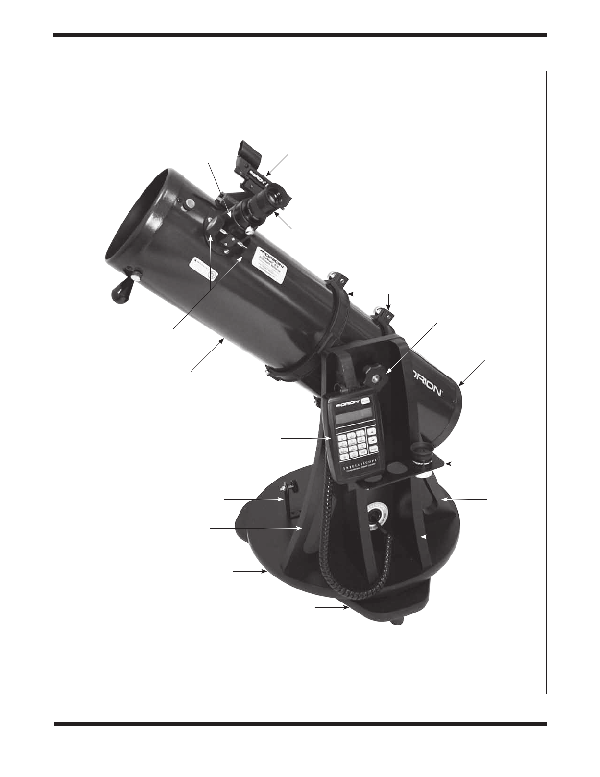
Focuser
EZ Finder II
reflex sight
Sirius Plössl
eyepiece
Navigation
knob
Focus wheels
Optical tube
assembly
Vertical stop
Carrying handle
Top baseplate
Tube rings
Altitude
tensioning knob
Bottom end ring
and primary
mirror cell
IntelliScope
Computerized
Object Locator
Eyepiece
rack
Carrying
handle
Altazimuth
base
Bottom baseplate
Figure 1. The StarBlast 6/6i, shown with IntelliScope system installed (#27191)
2
Page 3

Congratulations on your purchase of an Orion
Star Blast 6/6i IntelliScope Reflector telescope! It is
a versatile and compact astronomical instrument
designed to provide wondrous views of celestial
objects while offering unprecedented ease of use.
These instructions apply to both the StarBlast 6 (#10016,
without IntelliScope Computerized Object Locator) and the
StarBlast 6i (#27191), which includes the IntelliScope system.
If you purchased the StarBlast 6 (#10016), you may always
add the IntelliScope system (#27926) later to enjoy full digital
object location capability.
NOTE: The original model of the StarBlast 6 (#9964) is
not compatible with the IntelliScope Computerized Object
Locator.
If you purchased the #10016 StarBlast 6, you will enjoy breathtaking views of the Moon, planets, and even deep-sky objects
like the Orion Nebula. The telescope’s precision Newtonian
optics; portable, user-friendly design; and complement of outstanding features and accessories will make stargazing easy
and fun for the whole family.
If you purchased the #27191 StarBlast 6i IntelliScope, viewing
the night sky will be even easier, as you will have the ability
to pinpoint and view thousands of celestial objects with the
push of a button. Searching for objects will not be necessary
because the IntelliScope’s high-resolution digital encoders will
find them for you, in seconds!
Either way, we hope you enjoy your journey through the
universe!
These instructions will help you set up and use your StarBlast
6/6i telescope, please read them thoroughly.
WARNING: Never look at the sun with your telescope
(or even with just your eyes) without a professionally made
solar filter. Permanent eye damage or blindness could result.
Young children should use this telescope only with adult
supervision.
Avoid using the type of solar filter that screws into an eyepiece.
They are susceptible to cracking under the intense heat that
builds up near the focus point, and could cause severe retinal
damage. Use only the type of solar filter that covers the front
of the telescope. Also, be sure to leave the cover caps on the
finder scope when solar observing. Better yet, remove the finder
scope altogether when viewing the sun.
Table of Contents
1. Unpacking............................4
2. Parts List.............................4
3. Assembly of #10016 StarBlast 6
(without IntelliScope system)
.................6
4. Assembly of #27191
StarBlast 6i IntelliScope .................6
5. Final Assembly of Your Telescope
(StarBlast 6/6i) .......................11
6. Preparing to Use Your Telescope .........12
7. Observing With Your Telescope ..........13
8. Using the IntelliScope Computerized
Object Locator .......................16
A. Alignment ........................16
B. Overview of the IntelliScope
Computerized Object Locator .........18
C. Locating the Planets ................19
D. Locating Deep-Sky Objects
by Catalog........................20
E. Locating Deep Sky Objects
by Object Type ....................21
F. Locating Stars.....................22
G. Tours of the Best Objects ............23
H. The Identify Function ...............23
I. Adding User-Defined Objects .........24
J. The Function (FCN) Button...........24
K. The “Hidden” Functions .............25
9. Care and Maintenance .................26
10. Specifications of the StarBlast 6/6i ........27
11. Specifications of the IntelliScope System ...27
Appendix A: Collimating the Optics ..........28
Appendix B: Cleaning the Optics ............31
Appendix C: Troubleshooting the
IntelliScope System ...................31
Appendix D: Alignment Star Finder Charts.....34
Appendix E: Constellation Abbreviations ......38
Appendix F: ST Catalog . . . . . . . . . . . . . . . . . . .39
3
Page 4
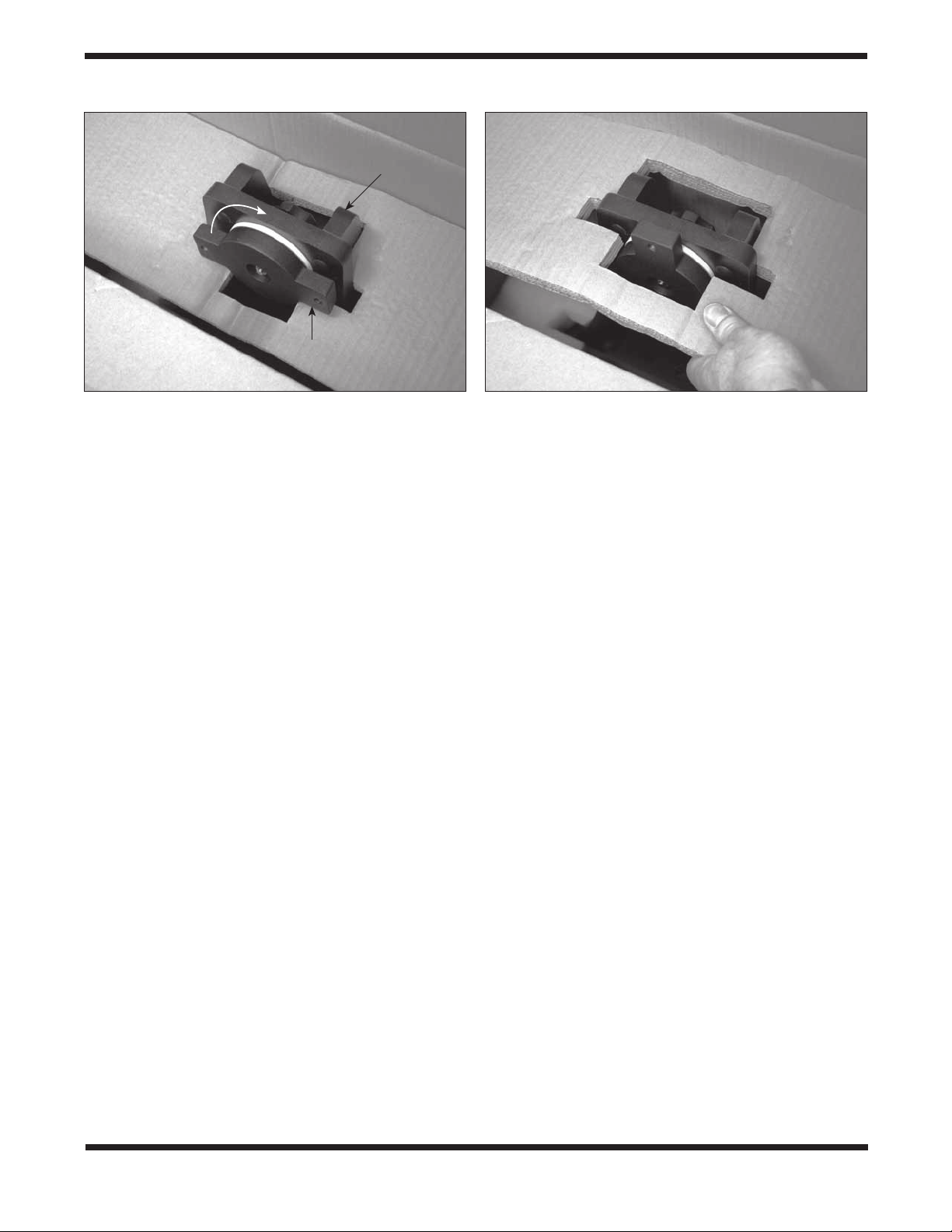
Top of base
side panel
Rotate
Telescope mounting bracket
Figure 2. To remove the cardboard insert from atop the altazimuth base, rotate the telescope mounting bracket so its long
axis is vertically oriented, then lift the insert off.
1. Unpacking
Carefully unpack the StarBlast 6/6i from its shipping box. We
recommend keeping the original shipping box and any smaller
accessory boxes contained within it. In the event that the telescope needs to be shipped to another location, or returned to
Orion for warranty repair, having the proper shipping containers will help ensure that your telescope will survive the journey
intact.
To remove the foam insert from the top of the altazimuth base,
rotate the telescope mounting bracket so that its long axis
is oriented vertically, then lift the foam insert out of the box
(Figure 2).
Make sure all the parts in the Parts List below are present. Be
sure to check the boxes carefully, as some parts are small.
If anything appears to be missing or broken, immediately call
Orion Customer Support (800-676-1343) for assistance.
2. Parts List
Qty. Description
1 Optical tube assembly
1 Altazimuth base
1 Tube rings, pair
1 Optical tube dust cover
1 25mm Sirius Plössl eyepiece,
1 10mm Sirius Plössl eyepiece
1 EZ Finder II reflex sight
1 Collimation cap
1 3-Hole eyepiece rack
1 Hex key, or Allen wrench (size 3/16")
The following parts are packed in small plastic bags
inside the main telescope box. They are needed only
for the StarBlast 6i IntelliScope model (#27191), not for the
StarBlast 6 (#10016) without IntelliScope. If you purchased the
latter, please do not discard these parts! Should you decide
at a later date to add the IntelliScope Computerized Object
Locator (#27926), you will need these parts. Keep them in a
safe place.
1 Azimuth encoder board
1 Azimuth encoder disk
1 Vertical stop L-bracket
1 Vertical stop bolt (with knob)
1 Jam nut for vertical stop bolt
1 Brass azimuth bushing
1 Aluminum spacer ring
3 Machine screws, 5mm (<1/4") long
6 Wood screws, 12mm (~½") long
2 Machine screws, 25mm (~1") long
2 Small hex nuts (for 25mm machine screws)
2 Small flat washers (for 25mm machine screws)
2 Small lock washers (for 25mm machine screws)
4
Page 5
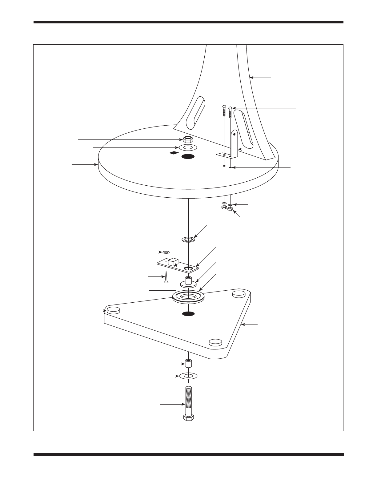
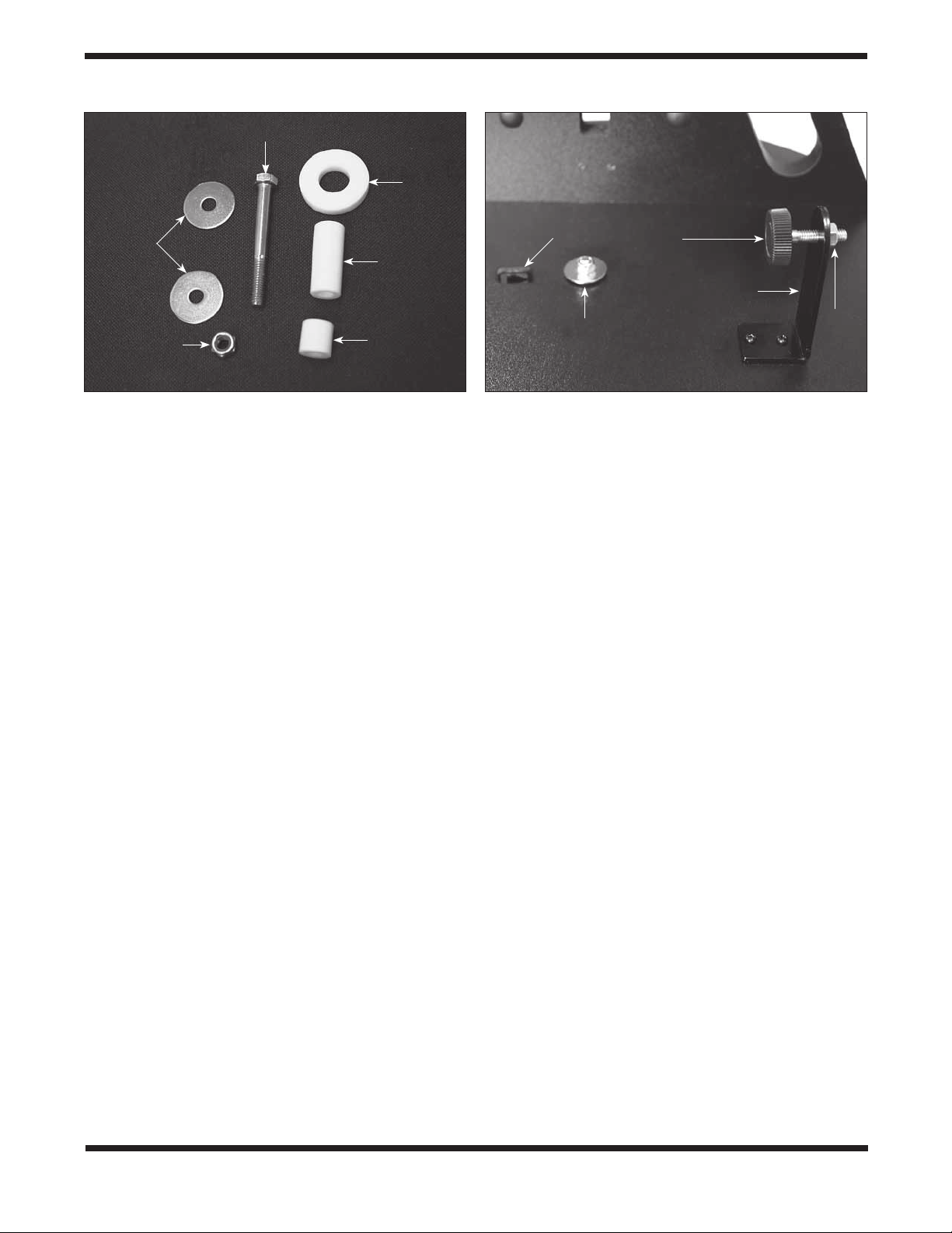
Hex lock nut
Fender washer
Vertical side panel
25mm (~1")
machine screws
Vertical stop
L-bracket
Top baseplate
Azimuth
bearing pads
(x3)
Washer
Wood screw
Modular jack
Pre-drilled
holes
Lock washers
Hex nuts
Wave spring
Azimuth encorder board
Brass azimuth bushing
Azimuth encoder disk
Bottom baseplate
Short azimuth bushing
Fender washer
Azimuth axis bolt
Figure 3. Illustration showing correct placement of the azimuth components of the IntelliScope system on the
altazimuth base.
5
Page 6
Fender
washers
Lock nut
Azimuth axis bolt
Long
azimuth
bushing
Short
azimuth
bushing
PTFE/
UHMW
bearing
ring
Altazimuth
encoder jack
Azimuth bolt
lock nut
Vertical
stop knob
Vertical stop
L-bracket
Jam
nut
Figure 4. When you disassemble the top and bottom
baseplates, you should see all of these parts.
The following parts are included in the small box containing the IntelliScope Computerized Object Locator that
comes with the StarBlast 6i IntelliScope model (#27191) only.
They are not included or needed with the standard StarBlast
6 (#10016).
1 Computerized Object Locator
1 Altitude encoder board
1 Encoder connector board
1 Altitude encoder disk
1 Coil cable
1 Altitude encoder cable (shorter)
1 Azimuth encoder cable (longer)
1 Wood screw, ½" long
8 Washers, 5/16" diameter
1 Wave spring
1 Compression spring
4 Cable retaining clips
2 Hook-and-loop strips (1 “hook” strip, 1 “loop” strip)
9-volt battery
3. Assembly of #10016
StarBlast 6 (without IntelliScope system)
The StarBlast 6/6i is partially assembled at the factory, for your
convenience. The altazimuth base is fully pre-assembled in the
#10016 configuration; that is, it is ready for use without the
IntelliScope system. If you purchased the #10016 StarBlast 6,
please skip to section 5: “Final Assembly of Your Telescope
(StarBlast 6/6i).”
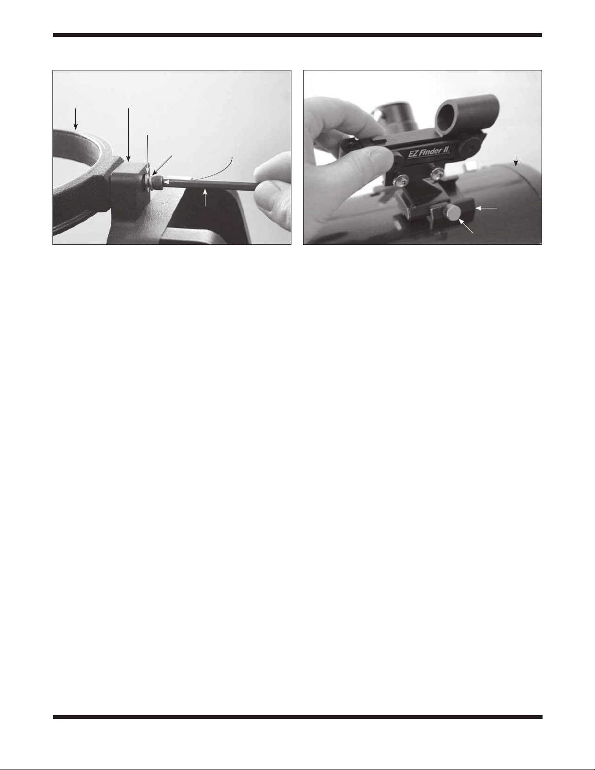
Figure 5. The vertical stop L-bracket and bolt (with knob),
shown installed in their correct orientations. The jam (hex)
nut on the opposite side of the L-bracket from the knob locks
the vertical stop bolt in the desired position.
4. Assembly of #27191
StarBlast 6i IntelliScope
If you purchased the #27191 StarBlast 6i IntelliScope,
some assembly is required to install the components of the
IntelliScope system on the altazimuth base. In fact, you will
first have to disassemble a portion of the base to remove a
couple of parts and install others that are necessary for the
IntelliScope system of function properly.
Installation of the IntelliScope System on the
Altazimuth Base
The assembly requires a small and a medium-sized Phillips
screwdriver and two adjustable crescent wrenches. You can
substitute a pair of pliers for one of the adjustable crescent
wrenches. You will also need a small (4" or so) piece of duct
tape, masking tape, or packing tape.
When tightening screws, tighten them until firm, but be careful
not to strip the threads by over-tightening.
Begin by placing the pre-assembled altazimuth base on the
floor or a table. For steps 1-11, refer to the schematic illustration in Figure 3 for correct placement of components.
1. To prepare the base for the installation of the IntelliScope
system components, you must first disassemble the top
baseplate from the bottom baseplate. To do this, use
one adjustable crescent wrench or a pair of pliers to
hold the hex head of the azimuth axis bolt steady on the
underside of the bottom baseplate while using another
adjustable crescent wrench to turn the hex lock nut
on the other end of the bolt. Remove the lock nut and
metal fender washer and set them aside. Now carefully
separate the two baseplates. In addition to the azimuth
axis bolt and a fender washer on the underside of the
6
Page 7
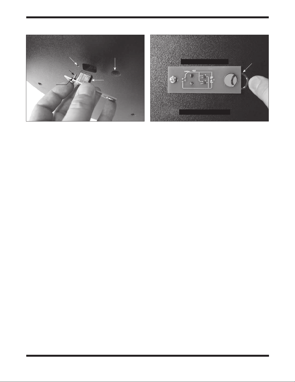
Under side of top baseplate
Pre-drilled
starter hole
Wood screw
Center hole
Altazimuth encoder board
Wave
spring
Washer
Modular jack
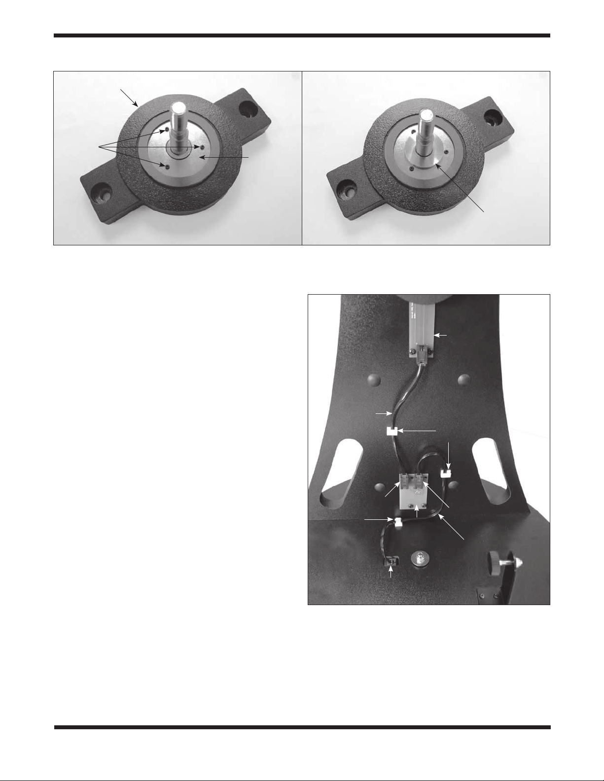
Figure 6. Install the azimuth encoder board on the underside of the top baseplate. Be sure to place one washer on
the screw after inserting the screw through its hole in the
azimuth board, then thread the screw into the predrilled
starter hole.
bottom baseplate, you should also see three white plastic
parts: a short azimuth bushing, a long azimuth bushing,
and a flat PTFE/UHMW bearing ring (Figure 4). The
bushings may have remained lodged in the center hole of
the baseplate(s) when you removed it. If that’s the case,
use a finger to push the bushing out of the hole. Set the
bottom baseplate and associated parts aside for now
while you install the vertical stop L-bracket on the top
baseplate.
2. Install the vertical stop L-bracket. It will be permanently
installed on the top baseplate (Figure 5). The vertical
stop L-bracket will be used before each observing
session to set the precise vertical orientation of the
optical tube, the procedure for which will be described
later. Once installed, the L-bracket will never have to be
removed because it does not interfere with the range of
motion of the optical tube between vertical and horizontal
positions.
To install the vertical stop L-bracket, insert the two 25mm
(~1") machine screws through the two holes in the
L-bracket’s foot. Then insert the screws into the holes in
the top baseplate, with the L-bracket oriented as shown
in Figure 5. On the underside of the top baseplate,
place a small lock washer on the end of each screw,
then thread on a small hex nut. While holding the hex nut
stationary with two fingers, tighten the screw with a small
Phillips screwdriver. Repeat for the other screw. Now the
L-bracket is secured in place.
Note: You may discard the two small flat washers for the
25mm machine screws that were included in the hardware kit;
they are not needed.
Under side of top baseplate
Figure 7. Wedge the wave spring between the azimuth
encoder board and the baseplate and align the “hole” in the
wave spring with the central hole in the baseplate.
3. Thread the vertical stop bolt and knob into the
corresponding hole in the vertical stop bracket, in the
orientation show in Figure 5. Thread it though so that
1/2" or so of the bolt emerges on the other side of the
L-bracket, then thread on the jam nut. You will adjust the
position of the vertical stop bolt and tighten the jam nut
later, when initializing the IntelliScope system prior to
using it for the first time.
4. Attach the azimuth encoder board to the underside of the
top baseplate (Figure 6). Insert a wood screw through
the slot in the azimuth encoder board, then place a
washer over the tip of the screw. Now hold the encoder
board so that the modular jack and large hole in the
encoder board line up with their corresponding holes
in the baseplate. Insert the screw tip into the pre-drilled
starter hole and screw it in with a Phillips screwdriver
until just tight. The screw should not be fully tightened;
it should be tight, but not tight enough to prevent the
encoder board from moving in its slot.
5. Place the wave spring between the azimuth encoder
board and the bottom of the top baseplate as shown
in Figure 7. Position the wave spring so that it aligns
precisely with the central hole in the baseplate.
Now that the azimuth encoder is installed on the underside of
the top baseplate, be sure not to set the baseplate down on a
flat surface, as doing so could damage the encoder. Rather,
set the baseplate with attached vertical side panel assembly
on its side for now.
6. Place one fender washer on the azimuth axis bolt,
followed by the short nylon bushing. Then insert the bolt
through the central hole from the underside of the bottom
7
Page 8
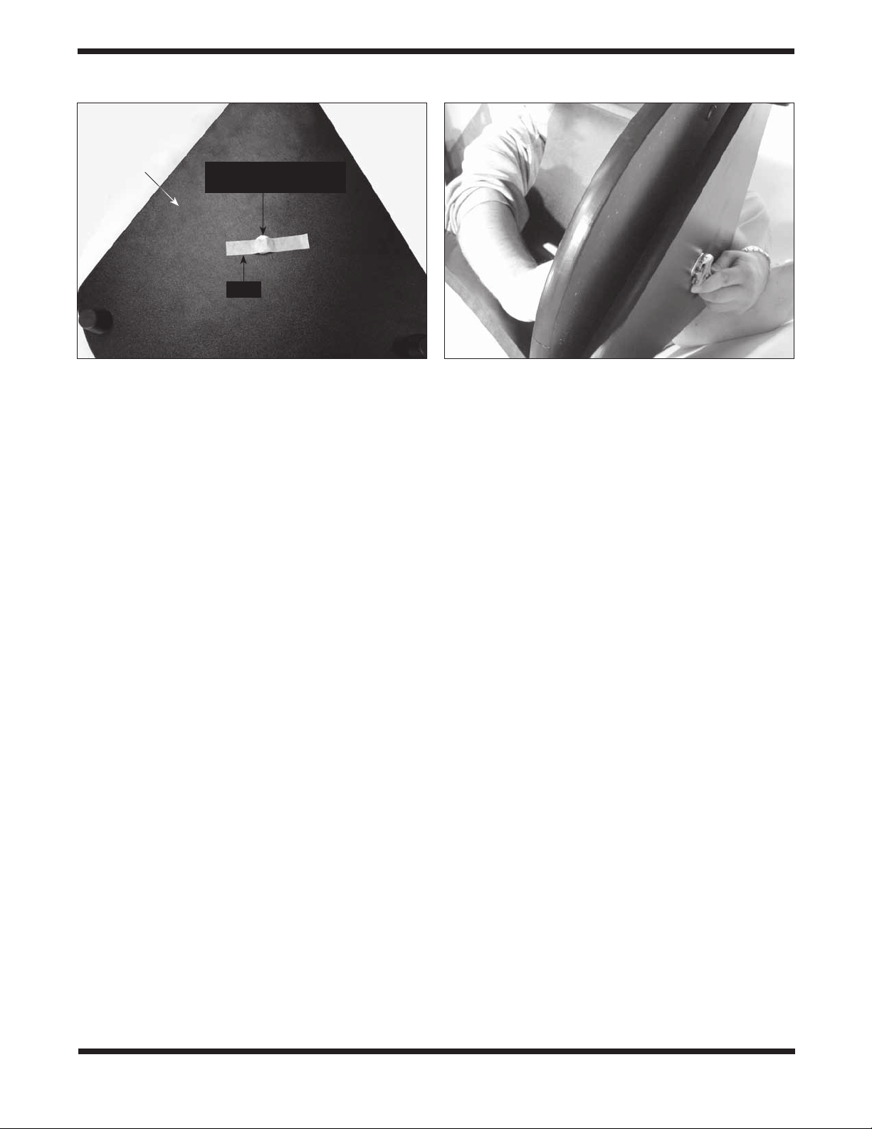
Under side
of bottom
baseplate
Head of azimuth axis bolt
(and fender washer)
Tape
Figure 8. Placing a piece of duct, masking, or packing tape
over the hex head of the azimuth axis bolt will keep it from
dropping downward when you replace the top baseplate onto
the bottom baseplate.
baseplate. Make sure the short nylon bushing seats up
into the hole.
7. Now temporarily place a piece of duct tape, masking
tape, or packing tape over the head of the azimuth axis
bolt (Figure 8). This will keep the bolt from sliding down
as you install the top baseplate, which you will do in step
10.
8. Place the azimuth encoder disk, flat side down, over the
azimuth axis bolt and rest it on the bottom baseplate.
Make sure you’ve got the correct encoder disk! The
azimuth encoder disk has a smaller center hole than the
altitude encoder disk.
9. Place the brass bushing onto the azimuth axis bolt so
that the wide end of the bushing is closest to the encoder
disk. Seat the bushing onto the encoder disk so that the
registration feature on the bushing goes into the hole in
the encoder disk. You may need to move the encoder
disk around on the azimuth axis bolt a bit for the bushing
to seat properly.
Note that for the IntelliScope version (#27191) of this telescope, you will not need the long nylon azimuth bushing and
PTFE/UHMW bearing disk that you removed during the baseplate disassembly (Figure 4). Those parts are only utilized for
the non-IntelliScope version of the StarBlast 6 (#10016).
10. Carefully position the top baseplate over the bottom
baseplate and lower it so the brass bushing goes up into
Figure 9. To reassemble the baseplates, tilt them only
slightly, as shown. Do not place them on their side. Use
one wrench to hold the azimuth axis bolt head steady while
turning the hex lock nut with the other wrench.
the center hole of the top baseplate. Place the remaining
fender washer onto the shaft of the azimuth axis bolt,
then thread the hex lock nut onto the end of the bolt and
tighten it only finger tight, for now. Note that the brass
bushing protrudes slightly above the surface of the top
baseplate. This is by design.
11. Tilt the assembled base at a slight angle (as little as
possible) and remove the tape from underneath the
bottom baseplate. Now, with one wrench (or pliers) hold
the head of the azimuth axis screw still while turning the
hex lock nut with the other wrench (Figure 9). Tighten the
hex lock nut just until the top fender washer is no longer
loose, then tighten the hex nut 3/16 to 1/4 turn beyond
that. This ensures proper spacing between the encoder
disk and the azimuth encoder board.
12. Attach the encoder connector board to the side panel.
Place a wood screw into each of the four holes of the
connector board and then a washer onto each screw.
Sliding the washers all the way down on the screw
shaft should help keep the screws from falling out while
installing the board. Still, the installation may take a bit
of dexterity, so don’t get frustrated if it takes a couple
tries. Align the screw tips with the four pre-drilled holes
in the side panel so that the modular jack fits into the
rectangular cutout. Then thread the screws into the holes
with a screwdriver. See Figure 10.
8
Page 9
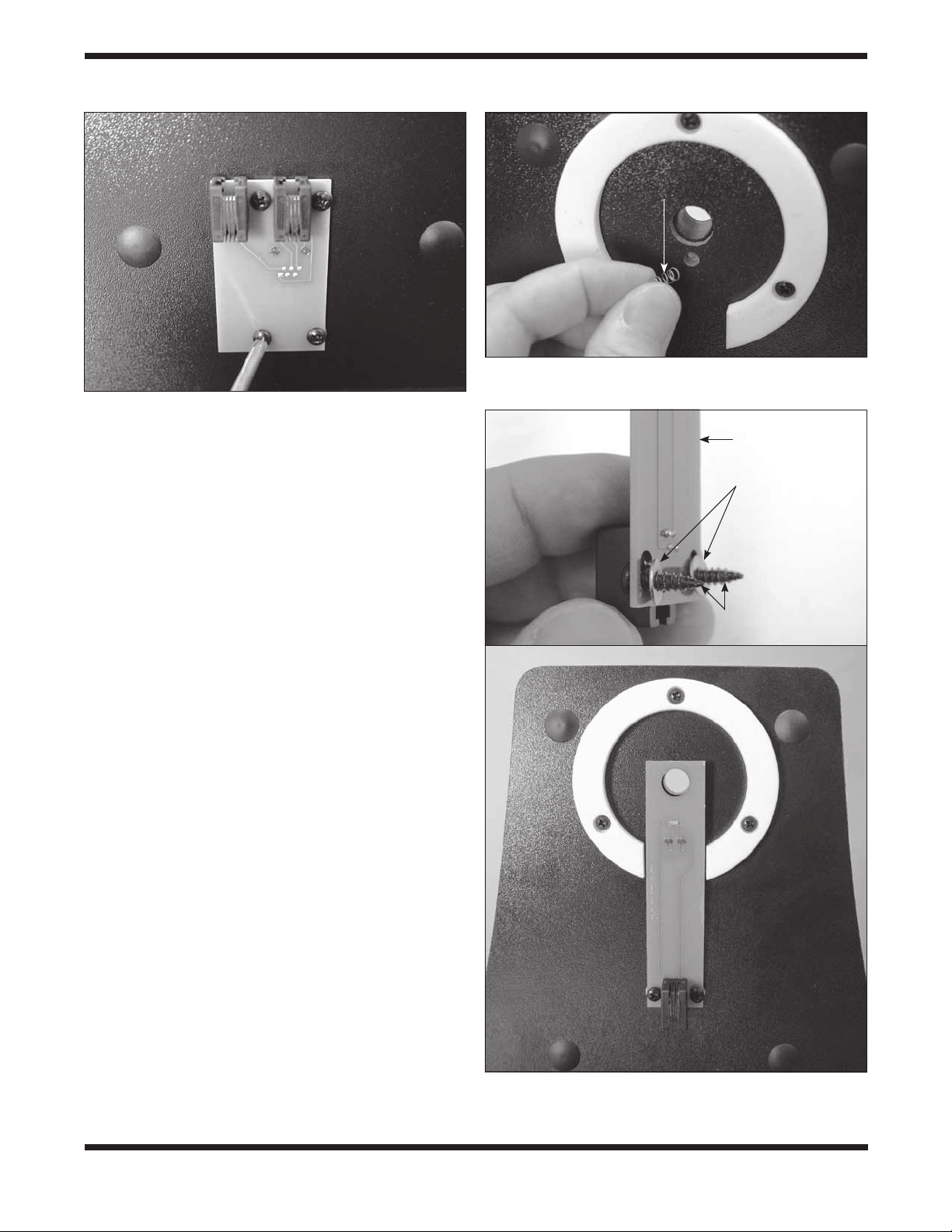
Figure 10. Installing the encoder connector board. There is
a washer on each screw, between the encoder board and the
side panel.
13. To attach the altitude encoder board and altitude encoder
disk, you must first remove the telescope mounting
bracket. Rotate the altitude axis tensioning knob
counterclockwise and remove it completely. You’ll see
two flat washers and a ball bearing ring remaining on the
mounting bracket’s shaft. To remove them you have to
rotate the outer washer counterclockwise to “unthread”
it from the bolt shaft, then slide the ball bearing ring and
inside washer off of the shaft. Now remove the telescope
mounting bracket from the side panel.
14. Insert the compression spring into the hole just below the
hole for the altitude axis bolt on the inside surface of the
side panel. When inserted as far as it will go, the spring
will still protrude from the hole by several millimeters
(Figure 11).
15. Now you will install the altitude encoder board. Place
two wood screws through the mounting holes in the
board, and then place two washers over the screw tips
as shown in Figure 12a. Thread the screws into the predrilled mounting holes with a Phillips screwdriver until
the board is secured, making sure that the large hole in
the encoder board is aligned with the hole in the side
panel and the board is pressing squarely against the
compression spring that you installed in the previous step
(Figure 12b). The screws should not be fully tightened;
they should be tight, but not tight enough to prevent the
altitude encoder from moving up and down within the
slots in the encoder board.
Compression
spring
Figure 11. Insert the compression spring into the small
hole just below the larger hole for the altitude axis bolt.
Altitude
encoder board
Washers
Wood screws
a
b
Figure 12. (a) Installing the altitude encoder board. Place
a washer on each screw, as shown. (b) The altitude encoder
board installed.
9
Page 10
Telescope mounting bracket
5mm
machine
screws
Altitude
encoder
disk
Aluminum
spacer ring
a b
Figure 13. (a) The altitude encoder disk is attached to the telescope mounting bracket with three 5mm machine screws.
The disk fits just inside the Ebony Star bearing ring. (b) The aluminum spacer ring should be installed on the telescope
mounting bracket’s shaft (altitude axis bolt) such that the flat side of the ring faces outward.
16. Attach the altitude encoder disk to the telescope
mounting bracket with the three 5mm (~1/4") machine
screws (Figure 13a). Place the aluminum spacer ring
on the telescope mounting bracket shaft with the flat
side of the ring facing outward (the opposite side has
Altitude
encoder
board
an indentation around the hole). See Figure 13b. Then
carefully insert the shaft through the hole in the altitude
encoder board and then the hole in the side panel. You
may have to carefully rotate the shaft back and forth a
little to get it through the hole, as it is a tight fit. Slide the
inside washer and ball bearing ring (which you removed
in step 13) onto the shaft, then “thread on” the outer
washer followed by the altitude tensioning knob.
17. Lastly, connect the encoder cables and install the cable
Altitude
encoder
cable
Cable
clips
retaining clips. Refer to Figure 14 for proper placement.
Connect one end of the azimuth encoder cable (the
longer of the two cables) to the encoder jack in the
top baseplate. Connect the other end to the encoder
connector board on the side panel. The cable should plug
into the jack on the right side of the encoder connector
board.
Plug one end of the altitude encoder cable into the
modular jack on the altitude encoder board. Connect the
Altitude
cable jack
Cable
clip
Encoder
connector
board
Azimuth
cable jack
Azimuth
encoder cable
other end of the cable to the jack on the left side of the
encoder connector board.
Use the provided cable retaining clips to secure the
altitude and azimuth cables neatly to the base. We
Azimuth encoder
board jack
recommend using one clip for the (shorter) altitude cable,
and two clips for the (longer) azimuth cable (Figure 14).
Figure 14. Connect the two encoder cables as shown.
The clips have adhesive backing; simply peel the paper
off the back of the clip and press the adhesive back to
the base where you want the clip to be located.
10
Page 11
Tube ring
Telescope
mounting
bracket
Flat
washer
Figure 15. Attaching a tube ring to the telescope mounting
bracket.
Lock
washer
Socket head
cap screw
Hex key
5. Final Assembly of
Your Telescope
(StarBlast 6/6i)
Now you will complete the assembly of your telescope by
installing the tube rings and optical tube assembly on the altazimuth base and attaching the included accessories.
Before getting started, locate the following items:
Qty. Description
1 Optical tube assembly
2 Tube rings
1 Telescope mounting bracket
1 EZ Finder II reflex sight
1 25mm Sirius Plössl eyepiece
1 10mm Sirius Plössl eyepiece
1 Eyepiece rack
2 Socket-head cap screws w/washers
(on tube rings)
Attach the Optical Tube to the Base
To attach the optical tube assembly to the altazimuth base you
will first need to equip the telescope mounting bracket with the
two tube rings. Rotate the bracket so one of the two through
holes in the bracket is accessible (Figure 15). Place a lock
washer and then a flat washer onto each of the socket-head
cap screws. Then insert the screw into the through hole as
shown in Figure 15 and thread it into one of the two tube rings
using the included hex key. Do not tighten it all the way; you’ll
do that after the telescope tube has been secured in the tube
rings. Now rotate the bracket 180° so the other through hole is
accessible. Fasten the second tube ring to the bracket with the
remaining washer-equipped screw using the hex key. Again,
don’t tighten the screw completely yet. Be sure to orient the
Front (open)
end of
optical tube
Dovetail
base
Thumbscrew
Figure 16. Attach the EZ Finder II in its dovetail base in the
orientation shown.
tube rings so that the knurled ring clamps are on the same
side.
Open the tube rings by loosening the knurled ring clamps.
Place the optical tube assembly in the open rings so the front
(open) end of the tube points upward. While grasping the optical tube firmly, close the rings around the tube and loosely
tighten the knurled ring clamps. Adjust the position of the optical tube in the tube rings so the bottom end of the tube just
clears the hardware in the center of the top baseplate.
To view through the StarBlast 6/6i comfortably, you can adjust
the orientation of the focuser by rotating the optical tube within
the tube rings. Loosen the knurled ring clamps on the tube
rings by a few turns. Now, gently rotate the optical tube within
the tube rings until the focuser is oriented to your liking. Then
tighten the knurled ring clamps to secure the optical tube in
that position.
Now that the optical tube is secured tightly in the tube rings,
tighten up each of the two socket-head cap screws that fasten
the tube rings to the telescope mounting bracket using the hex
key.
Install the EZ Finder II Reflex Sight
Slide the foot of the EZ Finder II bracket into the dovetail
base that is pre-installed on the optical tube (Figure 16). The
EZ Finder II should be oriented as in the figure. Tighten the
thumbscrew on the dovetail base to secure the EZ Finder II in
place. If it is present, remove the thin plastic battery shield tab
(not shown) from the battery casing prior to use and discard it.
Install the Eyepiece Rack
The eyepiece rack can be installed so that it can be removed,
or so it is permanently attached. Place the large portion of the
eyepiece rack’s “keyhole” mounting slots over the two preinstalled Phillips head screws on the side of the altazimuth
base, then slide the rack downward. If you want to be able
to remove the rack for transport or storage of the telescope,
be sure the screws are loose enough so you can lift the rack
and remove it from the base through the large opening of the
“keyhole.” If you wish to permanently attach the rack to the
11
Page 12
base, tighten the two screws with a screwdriver until the rack
is secured in place.
Insert an Eyepiece
Remove the small cap covering the focuser drawtube and
loosen the two eyepiece locking thumbscrews on the drawtube
collar. Insert the chrome barrel of the 25mm Sirius Plössl eyepiece into the focuser and secure it with the thumbscrews. You
can place the 10mm Sirius Plössl eyepiece in the eyepiece
rack for use later.
Congratulations! Your telescope is now fully assembled.
Remove the dust cap from the front of the telescope when it is
in use. Replace it when you are finished observing.
6. Preparing to Use Your
Telescope
This section applies to both the StarBlast 6 (#10016) and
Star Blast 6i IntelliScope (#27191).
It’s best to get a feel for the basic functions of the StarBlast 6/6i
during the day, before observing astronomical objects at night.
This way you won’t have to orient yourself in the dark! Find a
spot outdoors where you’ll have plenty of room to move the
telescope, and where you’ll have a clear view of some object
or vista that is at least 1/4 mile away. It is not critical that the
altazimuth base be exactly level (except when initially setting
the vertical stop knob position on the StarBlast 6i IntelliScope),
but it should be somewhat level to ensure smooth movement.
The StarBlast 6/6i was designed specifically for visual
observation of astronomical objects in the night sky. Like all
Newtonian reflector telescopes, it is not well suited for daytime
terrestrial usage because the image in the eyepiece will be
rotated somewhat from the normal, naked-eye view.
Placing the StarBlast 6/6i for Comfortable
Viewing
One of the great assets of the StarBlast 6/6i is its extremely
portable size. Due to its overall short length, you will find that
viewing while sitting next to the telescope is the most comfortable. If you wish to raise the telescope off the ground so that
it can be used while standing or sitting in a chair, then a platform, such as a milk crate, sturdy table, or the hood of a car
can be used.
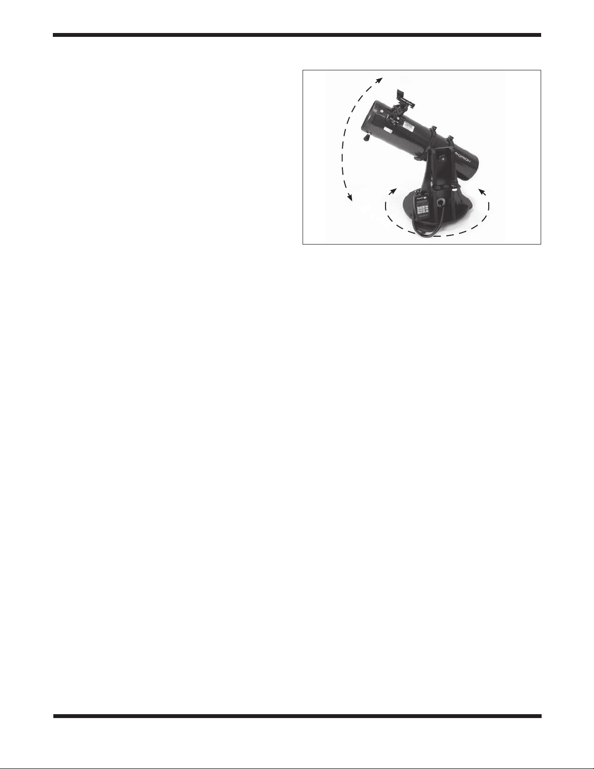
Altitude and Azimuth (Aiming the Telescope)
The StarBlast 6/6i’s altazimuth base permits motion along two
axes: altitude (up/down) and azimuth (left/right). See Figure
17. Moving the telescope up/down and left/right is the “natural”
way people aim objects, which makes pointing the telescope
intuitive and easy.
Simply take hold of the navigation knob and push or pull it to
move the telescope and base in the desired direction. Both
the altitude and azimuth motions can be made simultaneously
and in a continuous manner for easy aiming. This way you can
point to any position in the night sky, from horizon to horizon.
Altitude
Azimuth
Figure 17. The StarBlast 6/6i has two axes of motion:
altitude (up/down) and azimuth (left/right).
You may find it convenient to hold one hand on one of the carrying handles to help in leveraging the base while moving and
aiming the telescope.
When aiming the telescope in altitude, you may find the optical tube assembly is either too hard to move or does not stay
in place. Use the altitude tension knob to adjust the friction on
the altitude axis until you achieve the desired amount. Ideally,
you should adjust the tension on the altitude axis so that the
amount of friction roughly matches that of the azimuth axis
(which is not adjustable).
Focusing the Telescope
With the 25mm Sirius Plössl eyepiece in the focuser, aim the
optical tube so the front (open) end is pointing in the general
direction of an object at least 1/4-mile away. With your fingers,
slowly rotate one of the focus wheels until the object comes
into sharp focus. Go a little bit beyond sharp focus until the
image starts to blur again, then reverse the rotation of the
knob, just to make sure you’ve hit the exact focus point.
Operating the EZ Finder II Reflex Sight
The EZ Finder II reflex sight (Figure 18) works by projecting a
tiny red dot onto a lens mounted in the front of the unit. When
you look through the EZ Finder II, the red dot will appear to
float in space, helping you locate even the faintest of deep
space objects. The red dot is produced by a light-emitting
diode (LED), not a laser beam, near the rear of the sight. A
replaceable 3-volt lithium battery provides the power for the
diode.
To use the EZ Finder II, turn the power knob clockwise until
you hear a “click” indicating power has been turned on. With
your eye positioned at a comfortable distance, look through
the back of the reflex sight with both eyes open to see the red
dot. The intensity of the dot can be adjusted by turning the
power knob. For best results when stargazing, use the dimmest possible setting that allows you to see the dot without
difficulty. Typically, a dim setting is used under dark skies and
a bright setting is used under light-polluted skies or in daylight.
12
Page 13
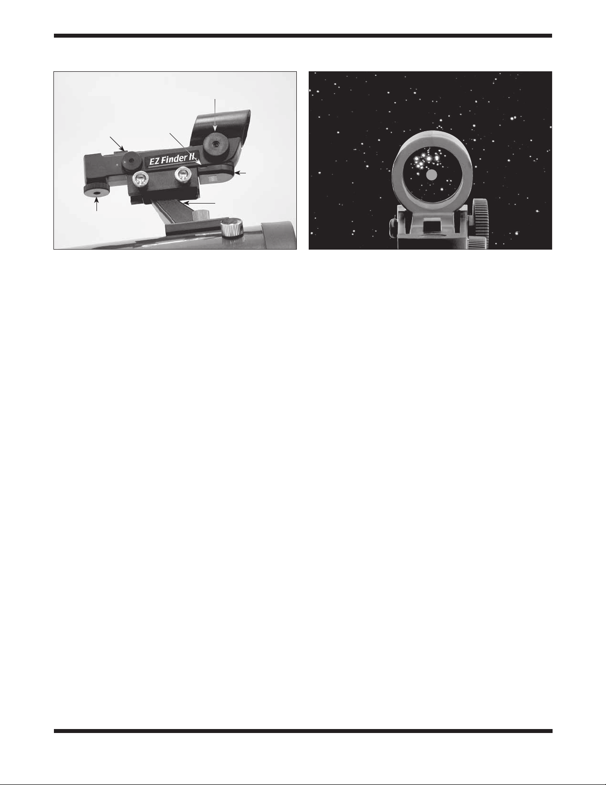
Power knob
Altitude
adjustment
knob
Slot for
battery
removal
Azimuth
adjustment
knob
Battery
casing
Mounting bracket
Figure 18. The EZ Finder II reflex sight. If it is present,
remove the thin plastic battery shield (not shown) from the
battery casing prior to use and discard it.
At the end of your observing session, be sure to turn the
power knob counterclockwise until it clicks off. When the two
white dots on the EZ Finder II’s rail and power knob are lined
up, the EZ Finder II is turned off.
Aligning the EZ Finder II
When the EZ Finder II is properly aligned with the telescope,
an object that is centered on the EZ Finder II’s red dot should
also appear in the center of the field of view of the telescope’s
eyepiece. Alignment of the EZ Finder II is easiest to do during daylight, before observing at night. Aim the telescope at a
distant object at least 1/4 mile away, such as a telephone pole
or chimney and center it in the telescope’s eyepiece. Now, turn
the EZ Finder II on and look through it. The object will appear
in the field of view near the red dot.
Note: The image in the eyepiece of the StarBlast 6/6i will not
be oriented right-side-up, but rather will be upside-down or
rotated somewhat from a correctly oriented, naked-eye view.
This is normal for Newtonian reflector telescopes.
Without moving the telescope, use the EZ Finder II’s azimuth
(left/right) and altitude (up/down) adjustment knobs (Figure
18) to position the red dot on the object in the eyepiece.
When the red dot is centered on the distant object, check to
make sure the object is still centered in the telescope’s field of
view. If not, recenter it and adjust the EZ Finder II’s alignment
again. When the object is centered in the eyepiece and on the
red dot, the EZ Finder II is properly aligned with the telescope.
Figure 19 simulates the view through the EZ Finder II.
Once aligned, the EZ Finder II will usually hold its alignment
even after being removed and remounted. Otherwise, only
minimal realignment will be needed.
Replacing the EZ Finder II Battery
Replacement 3-volt lithium batteries for the EZ Finder II are
available from many retail outlets. Remove the old battery by
inserting a small flat-head screwdriver into the slot on the battery casing (Figure 18) and gently prying open the case. Then
Figure 19. The EZ Finder II superimposes a tiny red dot on
the sky, showing right where the telescope is aimed.
carefully pull back on the retaining clip and remove the old battery. Do not over-bend the retaining clip. Slide the new battery
under the battery lead with the positive (+) side facing down
and replace the battery casing.
7. Observing With Your
Telescope
This section applies to both the StarBlast 6 (#10016) and
StarBlast 6i IntelliScope (#27191). Specific instructions on
how to use the IntelliScope Computerized Object Locator
with the StarBlast 6i IntelliScope are provided in the section
entitled “Using the IntelliScope Computerized Object Locator.”
Choosing an Observing Site
When selecting a location for observing, get as far away as
possible from direct artificial light such as street lights, porch
lights, and automobile headlights. The glare from these lights
will greatly impair your dark-adapted night vision. Avoid viewing over rooftops and chimneys, as they often have warm
air currents rising from them. Similarly, avoid observing from
indoors through an open (or closed) window, because the
temperature difference between the indoor and outdoor air will
cause image blurring and distortion.
If at all possible, escape the light-polluted city sky and head
for darker country skies. You’ll be amazed at how many more
stars and deep-sky objects are visible in a dark sky!
“Seeing” and Transparency
Atmospheric conditions vary significantly from night to night.
“Seeing” refers to the steadiness of the Earth’s atmosphere
at a given time. In conditions of poor seeing, atmospheric
turbulence causes objects viewed through the telescope to
“boil.” If, when you look up at the sky with your naked eyes,
the stars are twinkling noticeably, the seeing is bad and you
will be limited to viewing with low powers. This is because bad
13
Page 14
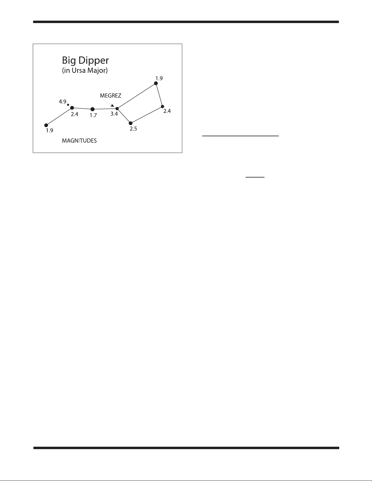
Figure 20. Megrez connects the Big Dipper’s “handle” to its
“pan.” If you cannot see Megrez, a magnitude 3.4 star, then
the viewing conditions are poor.
seeing affects images at high powers more severely. Planetary
observing may also be poor.
In conditions of good seeing, star twinkling is minimal and
images appear steady in the eyepiece. Seeing is best overhead, worst at the horizon. Also, seeing generally gets better
after midnight, when much of the heat absorbed by the Earth
during the day has radiated off into space.
Especially important for observing faint objects is good
“transparency” – air free of moisture, smoke, and dust. All
tend to scatter light, which reduces an object’s brightness.
Transparency is judged by the magnitude of the faintest stars
you can see with the unaided eye (6th magnitude or fainter is
desirable).
If you cannot see stars of magnitude 3.5 or dimmer, then conditions are poor. Magnitude is a measure of how bright a star
is: the brighter the star, the lower its magnitude. A good star
to remember for this is Megrez (mag. 3.4), which is the star in
the “Big Dipper” that connects the “handle” to the “pan” of the
dipper (Figure 20). If you cannot see Megrez, then you have
fog, haze, clouds, smog, or other conditions (such as light pollution) that are hindering your viewing.
Tracking Celestial Objects
The Earth is constantly rotating about its polar axis, completing one full rotation every 24 hours; this is what defines a “day.”
We do not feel the Earth rotating, but we see it at night from
the apparent movement of stars from east to west.
When you observe any astronomical object, you are in
essence watching a moving target. This means the telescope’s
position must be continuously adjusted over time to keep the
object in the field of view. This is easy to do with the StarBlast
6/6i because of its smooth motions on both axes. As the object
moves off towards the edge of the field of view, just lightly
nudge the telescope to re-center it.
Objects appear to move across the field of view faster at higher magnifications. This is because the field of view becomes
narrower.
Eyepiece Selection
By using eyepieces of different focal lengths, it is possible to
attain many magnifications, or powers, with the StarBlast 6/6i.
Your telescope comes with two Sirius Plössl eyepieces of different focal lengths: a 25mm, which provides a magnification
of 30x, and a 10mm, which yields 75x. Other eyepieces can be
used to achieve higher or lower powers. It is quite common for
an observer to own many eyepieces to access a wide range of
magnifications.
To calculate the magnification of a telescope-eyepiece combination, simply divide the focal length of the telescope by the
focal length of the eyepiece.
Telescope Focal Length (mm)
Eyepiece Focal Length (mm)
For example, the StarBlast 6, which has a focal length of
750mm, used in combination with the 25mm eyepiece, yields
a magnification of
750mm
25mm
Whatever you choose to view, always start by inserting your
lowest-power (longest focal length) eyepiece to locate and
center the object. Low magnification yields a wide field of view,
which shows a larger area of sky in the eyepiece. This makes
finding and centering an object much easier. Trying to find and
center objects with a high-power (narrow field of view) eyepiece is like trying to find a needle in a haystack!
Once you’ve centered the object in the eyepiece, you can
switch to a higher magnification (shorter focal length) eyepiece, if you wish. This is recommended for small and bright
objects, like planets and double stars. The Moon also takes
higher magnifications well.
The best rule of thumb with eyepiece selection is to start with
a low-power, wide-field eyepiece, and then work your way up
in magnification. If the object looks better, try an even higher
magnification eyepiece. If the object looks worse, then back
off the magnification a little by using a lower-power eyepiece.
What to Expect
So what will you see with your telescope? You should be able
to see bands on Jupiter, the rings of Saturn, craters on the
Moon, phases of Venus, and many bright deep-sky objects. Do
not expect to see color as you do in NASA photos, since those
are taken with long-exposure cameras and have “false color”
added. Our eyes are not sensitive enough to see color in faint
deep-sky objects, except in a few of the brightest ones.
Remember that you are seeing these objects with your own
eyes in real time, using your own telescope! That beats looking
at a picture in a book or on a computer screen, in our opinion.
Each session with your telescope will be a learning experience. Each time you work with your telescope it will get easier
to use, and celestial objects will become easier to find. There
is a big difference between looking at a well-made, full-color
NASA image of a deep-sky object in a lit room during the daytime, and seeing that same object in your telescope at night.
= Magnification
= 30x
14
Page 15
Magnification Limits
Every telescope has a useful magnification limit of about
2X per millimeter of aperture. This comes to 300X for
the StarBlast 6. Some telescope manufacturers will use
misleading claims of excess magnification, such as “See
distant galaxies at 640X!”. While such magnifications are
technically possible, the actual image at that magnification would be an indistinct blur.
Moderate magnifications are what give the best views. It
is better to view a small, but bright and detailed image
than a dim, unclear, oversized image.
One can merely be a pretty image someone gave to you. The
other is an experience you will never forget!
Objects to Observe
Now that you are all set up and ready to go, one critical decision must be made: what to look at?
A. The Moon
With its rocky surface, the Moon is one of the easiest and most
interesting targets to view with your telescope. Lunar craters,
marias, and even mountain ranges can all be clearly seen
from a distance of 238,000 miles away! With its ever-changing
phases, you’ll get a new view of the Moon every night. The
best time to observe our one and only natural satellite is during a partial phase, that is, when the Moon is NOT full. During
partial phases, shadows are cast on the surface, which reveal
more detail, especially right along the border between the dark
and light portions of the disk (called the “terminator”). A full
Moon is too bright and devoid of surface shadows to yield a
pleasing view. Make sure to observe the Moon when it is well
above the horizon to get the sharpest images.
Use an optional Moon filter to dim the Moon when it is very
bright. It simply threads onto the bottom of the eyepiece barrels (you must first remove the eyepiece from the focuser to
attach a filter). You’ll find that the Moon filter improves viewing comfort, and also helps to bring out subtle features on the
lunar surface.
B. The Sun
You can change your nighttime telescope into a daytime Sun
viewer by installing an optional full-aperture solar filter over
the front opening of the StarBlast 6/6i. The primary attraction
is sunspots, which change shape, appearance, and location
daily. Sunspots are directly related to magnetic activity in the
Sun. Many observers like to make drawings of sunspots to
monitor how the Sun is changing from day to day.
Important Note: Do not look at the Sun with any optical instrument without a professionally made solar filter, or permanent
eye damage could result.
C. The Planets
The planets don’t stay put like the stars, so to find them you
should refer to “This Month’s Sky Summary” in the Learning
Center section of our website (telescope.com). Venus, Jupiter,
and Saturn are the brightest objects in the sky after the Sun
and the Moon. Your StarBlast 6/6i is capable of showing you
these planets in some detail. Other planets may be visible but
will likely appear star-like. Because planets are quite small in
apparent size, optional higher-power eyepieces are recommended and often needed for detailed observations. Not all
the planets are generally visible at any one time.
JUPITER: The largest planet, Jupiter, is a great subject for
observation. You can see cloud bands on the disk of the giant
planet and watch the ever-changing positions of its four largest
moons: Io, Callisto, Europa, and Ganymede.
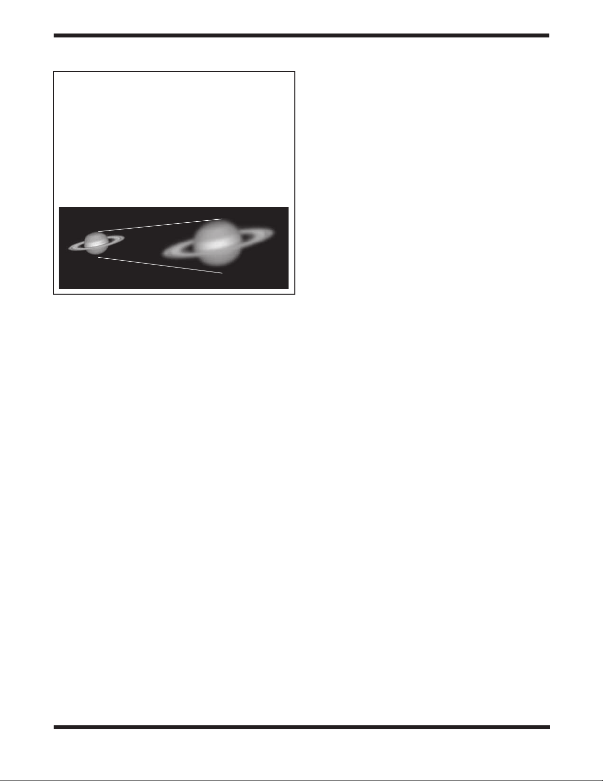
SATURN: The ringed planet is a breathtaking sight when it is
well positioned. The tilt angle of the rings varies over a period
of many years; sometimes they are seen edge-on, while at
other times they are broadside and look like giant “ears” on
each side of Saturn’s disk. A steady atmosphere (good seeing)
is necessary for a good view. You will probably see a bright
“star” close by, which is Saturn’s brightest moon, Titan.
VENUS: At its brightest, Venus is the most luminous object in
the sky, excluding the Sun and the Moon. It is so bright that
sometimes it is visible to the naked eye during full daylight!
Ironically, Venus appears as a thin crescent, not a full disk,
when at its peak brightness. Because it is so close to the Sun,
it never wanders too far from the morning or evening horizon.
No surface markings can be seen on Venus, which is always
shrouded in dense clouds.
D. The Stars
Stars will appear like twinkling points of light. Even powerful
telescopes cannot magnify stars to appear as more than a
point of light. You can, however, enjoy the different colors of
the stars and locate many pretty double and multiple stars. The
gorgeous two-color double star Albireo in Cygnus is a favorite.
Defocusing a star slightly can help bring out its color.
E. Deep-Sky Objects
Under dark skies, you can observe a wealth of fascinating
deep-sky objects, including gaseous nebulas, open and globular star clusters, and a variety of different types of galaxies.
Most deep-sky objects are very faint, so it is important to find
an observing site well away from light pollution. Take plenty
of time to let your eyes adjust to the darkness. Do not expect
these subjects to appear like the photographs you see in books
and magazines; most will look like dim gray smudges. Our
eyes are not sensitive enough to see color in deep-sky objects
except in a few of the brightest ones. But as you become more
experienced and your observing skills get sharper, you will be
able to discern more and more subtle details and structure.
To find deep-sky objects in the sky, it is best to consult astronomy software, or a star chart or planisphere. These guides
15
Page 16

will help you locate the brightest and best deep-sky objects
for viewing with your StarBlast 6/6i. Of course, if you purchased the StarBlast 6i IntelliScope, you will be able to easily
locate dozens of deep-sky objects in a given evening with the
IntelliScope Computerized Locator!
You can also try low-power scanning of the Milky Way. Use the
25mm eyepiece and just cruise through the “star clouds” of our
galaxy. You’ll be amazed at the rich fields of stars and objects
you’ll see! The Milky Way is best observed on summer and
winter evenings.
8. Using the IntelliScope
Computerized Object
Locator
This section applies only to the StarBlast 6i IntelliScope
(#27191), which comes with the Computerized Object
Locator.
Coil cable
jack
RS-232
jack
Backlit
liquid-crystal
display
The IntelliScope Computerized Object Locator (controller)
(Figure 21) will provide quick, easy access to thousands of
celestial objects for viewing with your telescope.
The controller’s user-friendly keypad combined with its database of more than 14,000 celestial objects put the night sky literally at your fingertips. You just select an object to view, press
Enter, then move the telescope manually following the guide
arrows on the liquid crystal display (LCD) screen. In seconds,
the IntelliScope’s high-resolution, 9,216-step digital encoders
pinpoint the object, placing it smack-dab in the telescope’s
field of view!
A. Alignment
This section will familiarize you with the alignment procedure
for the IntelliScope system.
Powering the Controller
Install the included 9-volt alkaline battery in the battery compartment on the back of the controller. Make sure the positive
and negative terminals are oriented as indicated by the labels
next to the terminals in the battery compartment. To turn the
controller on, firmly press the Power button. The LED lights
will activate and the LCD screen will display its introduction
message. The intensity of the illumination can be adjusted by
repeatedly pressing the Power button. There are five levels of
LED brightness. Choose a brightness level that suits your conditions and needs. (Dimmer settings will prolong battery life.)
To turn the controller off, press and hold the Power button for a
few seconds, then release it.
To conserve battery life, the controller is programmed to shut
itself off after being idle for 50 minutes. So, make sure to press
a button at least once every 50 minutes if you do not want
the controller to turn off. If the controller does turn off, you will
need to perform the initial alignment procedure again.
If the LCD screen and the buttons’ backlighting automatically
begin to dim, it’s time to change batteries.
Illuminated
pushbuttons
Figure 21. The IntelliScope Computerized Object Locator
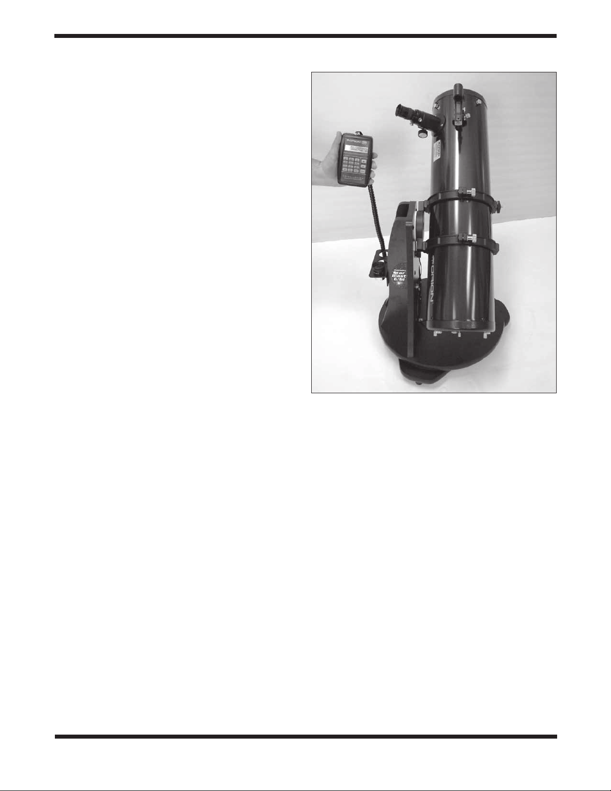
Initial Vertical Alignment
After powering up the controller, the top line of the LCD display will read: “POINT VERTICAL.” If the top line reads “ALIGN
DEC MARK,” simply press the up arrow button. The top line
will now read “POINT VERTICAL”, and you are set to use the
object locator with your IntelliScope Dobsonian.
If the vertical stop you installed on the top baseplate during
assembly of the telescope is properly adjusted (see below),
rotate the optical tube upward until the rear end ring comes
in contact with the vertical stop knob, as shown in Figure 22.
You may have to raise or lower the tube in the tube rings to
achieve contact between the flat portion of the rear end ring
and the vertical stop knob. Once the optical tube is in the vertical position, press the Enter button to start the two-star alignment procedure.
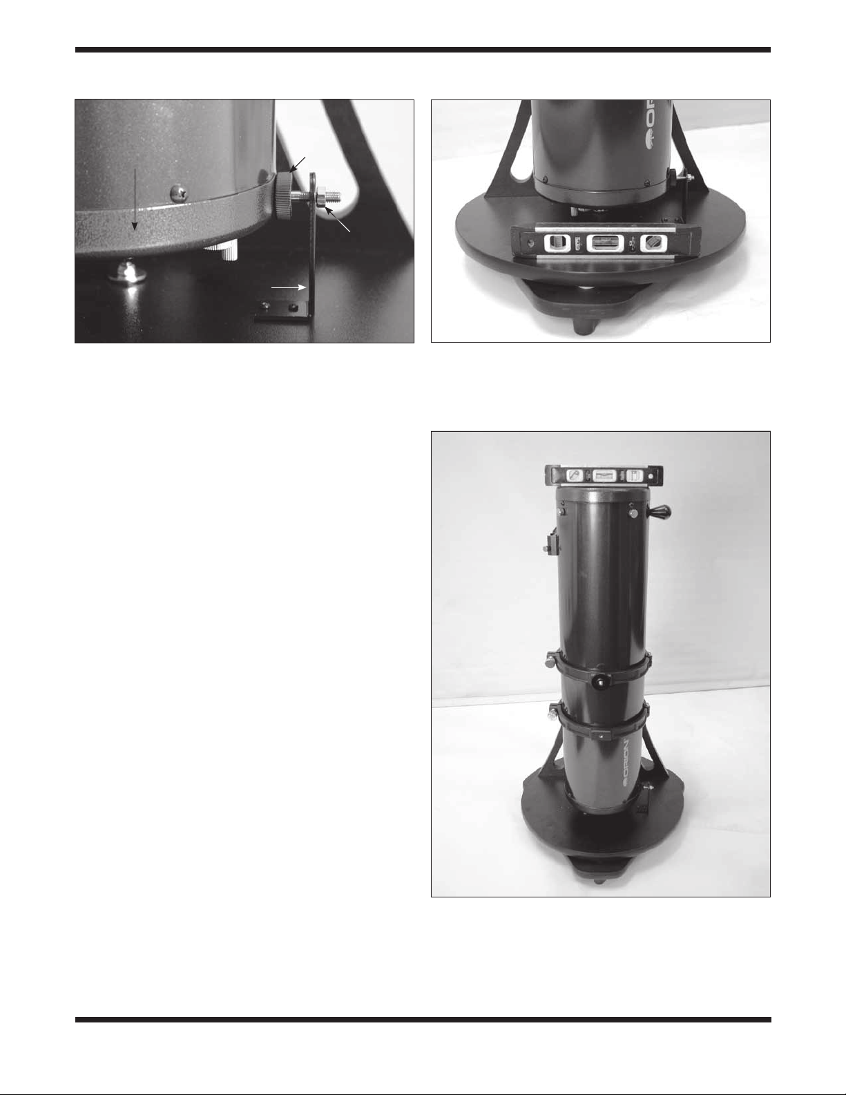
Setting the Vertical Stop
For the IntelliScope system to work accurately, the vertical
stop must be precisely set so that the optical tube is truly perpendicular to the azimuth axis of the base when the controller
says “POINT VERTICAL.” For this you will need a carpenter’s
level, which you can find at just about any hardware store.
First, make sure the base itself is level. Place the carpenter’s
level on the top baseplate and rotate the base 180˚ in azimuth
(Figure 23). The level should indicate that the base is level
through the entire rotation. If not, then reposition the base on
the ground, or place shims underneath the feet until the base
stays level though a 180˚ rotation.
Next, rotate the optical tube upward until the rear end ring
comes in contact with the vertical stop knob. Place the carpenter’s level across the top of the optical tube (Figure 24). Is
User-friendly
keypad
16
Page 17
Rear end
ring
Vertical
stop
knob
Jam nut
Vertical stop
L-bracket
Figure 22. Once the vertical stop is adjusted and set
initially, pointing the optical tube vertically is as easy as
rotating the tube until the bottom end ring contacts the
vertical stop knob, as shown. Make sure the middle of the
end ring – not the rounded bottom edge – contacts the
vertical stop knob.
it level? If so, thread the jam nut tight against the back of the
L-bracket to secure the vertical stop knob in that exact position. If the top of the optical tube is not level, thread the vertical
stop bolt in or out as needed until the top of the tube is level
when the end ring comes in contact with the vertical stop knob.
Then secure the vertical stop bolt in place with the jam nut.
Once the vertical stop bolt is accurately adjusted, it should not
need adjustment again. The base does not need to be level
for the IntelliScope system to function properly; the base only
needs leveling when initially setting the vertical stop.
Simple Two-Star Alignment
After setting the vertical position of the optical tube, a simple
two-star alignment process is all that is needed to ready the
IntelliScope system for operation. This is a great simplification
from many other computerized systems, which require you to
enter data such as your longitude, latitude, and time zone. For
the IntelliScope controller to accurately find objects, you only
need to center two bright stars in your telescope and indicate
to the controller which two stars you have centered. This is
quite easy to do. For your convenience, we have provided
finder charts for the alignment stars in Appendix D. Use the
finder chart to locate and identify two bright stars in your current night sky. For best results, choose two stars that are at
least 60˚ apart from each other. (The width of your fist at arm’s
length is about 10˚, so you want the stars to be at least six fistwidths apart.)
So, the optical tube is now in the vertical position and you’ve
chosen two bright stars in the sky to use for alignment. The
telescope should have a high-power eyepiece, such as the
10mm Sirius Plössl, in the eyepiece holder and the finder
scope should be properly aligned with the telescope (these
procedures are described elsewhere in this manual). The LCD
screen will state on its top line “ALIGN STAR 1,” with the name
of a star flashing on the second line.
Figure 23. Place a carpenter’s level on the altazimuth
base as shown. Add shims under the three feet as needed
so that the base stays level through a 180-degree rotation
in azimuth. Once the vertical stop is set, the base does not
need to be level to function properly.
Figure 24. Once the base is leveled, point the optical tube
up until the mirror cell (bottom end ring) contacts the vertical
stop knob. Then place the carpenter’s level across the top of
the tube as shown and adjust the vertical stop knob until the
tube is level. After each adjustment of the vertical stop knob,
make sure to re-establish contact between the telescope end
ring and the knob before checking the carpenter’s level.
17
Page 18
Use the arrow buttons to scroll through the names of the
alignment stars. The up arrow button scrolls through the stars
alphabetically from A to Z. The down arrow button scrolls
alphabetically backwards, from Z to A. When you arrive at the
name of the star you wish to align on, you can begin to move
the telescope so that it is pointing at that star (but don’t press
the Enter button yet).
Note: The controller will not accept Polaris as the first alignment star. This helps prevent the pointing accuracy from
decreasing over time. It is OK to use Polaris as the second
alignment star, however.
Take hold of the “navigation knob” on the optical tube and
move the telescope so that it is pointing in the general area
of the alignment star. Aim the telescope so the alignment star
appears in finder scope. Be careful not to confuse the alignment star with other stars in the area when doing this. (It will
likely be the brightest star in the field of view.) Now, move the
telescope until you have centered the star on the crosshairs of
the finder scope. Look into the eyepiece of the telescope, and
you should see the alignment star in the field of view of the
eyepiece. If it isn’t, then your finder scope is out of alignment
with your telescope and will need to be adjusted. Once the
alignment star is in the eyepiece’s field of view, center it in the
eyepiece as best you can by making small movements to the
telescope. (If you have one, an illuminated reticle eyepiece is
great for centering alignment stars). Once this is done, press
the Enter button on the controller. You have now completed
one-half of the two-star alignment.
The LCD screen will now read “ALIGN STAR 2” on the first line
with an alignment star’s name flashing on the second line. As
before, scroll through the names of the stars with the arrow
buttons until you reach your second chosen alignment star.
Repeat the procedure described above for your second alignment star. When you have aligned on the second star, press
the Enter button. The LCD will then display a number. It is the
alignment error factor, or “warp” (W) factor.
The Alignment Error (Warp) Factor
The “warp” alignment error factor essentially lets you know
if your alignment was accurate or not. Ideally, this number
should be as low as possible, but any “W” of 0.5 or smaller
is acceptable (regardless of + or - sign). Warp factors of ±0.3
and ±0.4 are the most common. Warp factors under ±0.2 are
typically not achievable (but kudos to you if you get one!). If
you complete an alignment and the warp factor is larger than
±0.5 (e.g., +0.6, -0.6, +0.7, -0.7, etc.), then you must turn the
controller off (by holding down the Power button) and begin the
alignment procedure again. Otherwise, there is no guarantee
that the controller will consistently place objects within the field
of view of a medium-low power eyepiece.
An unacceptable warp factor may indicate that you aligned on
the wrong star or did not have the telescope initially in a precisely vertical position. If you are having problems getting the
warp factor at or below ±0.5, see the troubleshooting section
in Appendix C.
Your IntelliScope Computerized Object Locator is now ready
to find objects. Replace the high-powered eyepiece you used
Figure 25. If you’re positioned to the left of the telescope
and face the direction the optical tube is pointed, the guide
arrows on the Computerized Object Locator will correspond
exactly with the direction you should move the telescope to
pinpoint the selected object.
for centering the alignment stars with a low-power, wide-field
eyepiece, such as the 25mm Sirius Plössl.
B. Overview of the IntelliScope Computerized
Object Locator
The IntelliScope Computerized Object Locator (controller) has
been specifically designed for ease of use. This section will
help familiarize you with the basic layout and operation of the
controller.
Pushbuttons
Besides the Power, Enter, ID, FCN, and up/down arrows, all
pushbuttons have letters on them with numbers above them
(Figure 21). The letters designate the function of the pushbut-
ton. The numbers above them are used for entering numerical
data only; the numbers are never active until a function is first
chosen. The numbers are arranged like a telephone keypad
for ease of number entry. None of the function buttons will
work properly until an initial alignment, as outlined previously,
is completed. If you press a function button be-fore the twostar alignment is completed, the controller will display “MUST
STAR ALIGN.” Turn the unit off, then on again (by using the
Power button), to begin the alignment routine again.
18
Page 19

a.
b.
c.
The Guide Arrows
The controller leads you to astronomical targets with guide
arrows displayed on the LCD screen. After an object is selected to view, you will see two guide arrows, one that points left
or right, and one that points up or down. Move the telescope
tube in the corresponding direction of the guide arrows. If you
are standing to the left of the telescope and facing the same
direction the telescope is pointed, the guide arrows will exactly
correspond with the direction you should move the telescope
(Figure 25). Otherwise, if an up arrow is displayed, move the
telescope tube upward, if a down arrow is displayed, move the
telescope tube downward, if a left arrow is displayed, rotate the
telescope counterclockwise, and if a right arrow is displayed,
rotate the telescope clockwise. There is a number next to each
guide arrow that indicates how far the telescope needs to be
moved to reach the selected object. As you move the telescope toward the object, this number will decrease. When the
number goes below ten, the figure will be displayed in tenths;
this helps to make small, precise movements to the telescope
tube in order to bring the object into your field of view. When
both numbers reach zero, stop moving the telescope. The
object will be within the field of view of a medium- to low-power
eyepiece (25mm focal length or longer).
For example, look at Figure 26a, which shows the LCD screen
for someone trying to locate M51, otherwise known as the
Whirlpool Galaxy. The first arrow is pointing right and gives a
number of 34. The second arrow is pointing up and displays
the number 12. This means that the telescope tube should be
moved to the right (clockwise) and up. When you are close to
Figure 26. This sequence
of pictures illustrate how the
Computerized Object Locator’s
guide arrows look as you are
finding a celestial object. (a)
When the optical tube is aimed
far away from the object’s
location, there will be a number
(from 10 to 179) to the left of
the guide arrows. (b) When
the scope is aimed close to
the object, each guide arrow
will display a number on its
immediate left (from 0 to 9)
and immediate right (from 0
to 9); the number on the left is
whole number increments, while
the number on the right is in
increments of tenths. This helps
in making small movements to
the telescope to pinpoint the
object’s location. (c) When the
guide arrows display “0.0 0.0”,
the object will be within the
field of view of the telescope
(with a 25mm or longer focal
length eyepiece).
M51, the numbers will be displayed in tenths, as is shown in
Figure 26b. When the numbers reach zero (Figure 26c), the
telescope will be pointed right at the Whirlpool Galaxy.
It is easiest to move the telescope in one direction at a time
(say altitude) until the corresponding number reached “0.0”.
Then move the scope in the other direction (azimuth) until that
number also reads “0.0”.
If the object selected to view is currently located below the
horizon, the word “HORIZON” will flash before the guide
arrows are displayed. Choose another object to view.
C. Locating the Planets
By far the most popular objects for viewing, after the Moon, are
the planets. Since the other eight planets in our solar system
are also orbiting the Sun, they do not appear in fixed positions
in the night sky like deep-sky objects and stars do. Because of
this, the controller requires you to input the date before it can
find the planets.
To find planets with your IntelliScope Computerized Object
Locator, use the following procedure:
1. Press the Planet button on the controller.
2. The LCD screen will display a date similar to the
following:
3. The number after the word “DATE” will be flashing and
represents the day of the month. Input the two-digit day
using the number buttons.
4. The three-letter month will now be flashing. Use the
arrow buttons to scroll to the present month and then
press the Enter button.
5. Now the year will flash. Input the year using the number
buttons.
If you make a mistake while inputting the date, press the Enter
button at any time while still within the Planet button function.
The LCD screen will then display the last date input, with the
two-digit day after the word “DATE” flashing. Input the correct
date as outlined above.
Now, to choose a planet to view, press the arrow buttons
and scroll through the planets. The planet’s name will be displayed in the upper left section of the LCD screen, with the
guide arrows on the upper right of the LCD screen. Move the
telescope in the corresponding direction shown by the guide
arrows.
The lower left screen shows the constellation that the planet
appears in, with its present co-ordinates given in right ascension and declination. When you are finished viewing the planet, you may scroll to another planet by using the arrow buttons.
The features and details you can see will vary from planet to
planet. The following descriptions give a brief overview of what
to expect when viewing them:
MERCURY Mercury is often so close to the Sun that it cannot
be seen. Sometimes it is visible for a brief period after the Sun
sets, and sometimes it’s visible in the morning just before the
Sun rises. Mercury does not really show any detail, but is quite
bright. With your telescope, you will be able to investigate this
19
Page 20

planet’s orange-colored hue. Like Venus, Mercury sometimes
appears as a crescent, rather than as a full disk.
VENUS At its brightest, Venus is the most luminous object in
the sky, excluding the Sun and the Moon. It is so bright that
sometimes it is visible to the naked eye during full daylight!
Ironically, Venus appears as a thin crescent, not a full disk,
when at its peak brightness. Because it is close to the Sun,
it never wanders too far from the morning or evening horizon.
No surface markings can be seen on Venus, which is always
shrouded in dense clouds.
MARS The Red Planet makes its closest approach to Earth
every two years. During close approaches you’ll see a red
disk, possibly some light and dark regions, and maybe the
polar ice cap. To see surface detail on Mars, you will need a
high power eyepiece and very steady air!
JUPITER The largest planet, Jupiter, is a great subject for
observation. You can see the disk of the giant planet and
watch the ever-changing positions of its four largest moons –
Io, Callisto, Europa, and Ganymede. Higher power eyepieces should bring out the cloud bands on the planet’s disk and
maybe even the Great Red Spot.
SATURN The ringed planet is a breathtaking sight when it is
well positioned. The tilt angle of the rings varies over a period
of many years; sometimes they are seen edge-on, while at
other times they are broadside and look like giant “ears” on
each side of Saturn’s disk. A steady atmosphere (good seeing)
is necessary for a good view. You will probably see a bright
“star” close by, which is Saturn’s brightest moon, Titan.
URANUS Uranus is a faint planet, and requires high powers
(at least 100x) before it starts to show any detail that distinguishes it from stars. Uranus will appear as a pale, blue-green
disk.
NEPTUNE Like Uranus, Neptune will require high powers before showing anything to distinguish itself from stars.
Neptune will appear as a bluish-colored disk, possibly with
a very faint moon nearby if you are using a larger-aperture
IntelliScope.
PLUTO Smaller than our own Moon, Pluto is very, very faint
and shows little more than a point of light similar to a star. Even
the Hubble Space Telescope is unable to show much detail on
Pluto. Many amateur astronomers note how Pluto moves with
respect to background stars (over several nights) in order to
confirm their observation of our most remote planet.
D. Locating Deep-Sky Objects by Catalog
Catalogs are groups of deep sky objects of interest that have
been assembled and given designations. Very often a deepsky object will have a catalog number, as well as a “common”
name. For example, the Orion Nebula is listed in the Messier
catalog as “M42.” The controller has three catalogs built-in:
The Messier catalog (M), the New General Catalog (NGC),
and the Index Catalog (IC). Many of the objects in the Messier
catalog also have NGC catalog designations.
The Messier Catalog
The Messier catalog contains 110 galaxies, nebulas, and star
clusters identified by the famous French astronomer Charles
Messier and his colleagues in the late 1700’s. These are some
of the most popular celestial attractions observed by amateur
astronomers.
To view an object from the Messier catalog, press the M button. Then enter the number of the Messier object you wish to
view using the numeric buttons and press the Enter button. For
example, to view Messier 57, also known as “the Ring Nebula,”
you would press the M button, then press the “5” button, then
press the “7” button, followed by the Enter button. If the number
of the Messier object you wish to view contains three dig-its,
it is not necessary to press Enter after inputting the third digit.
The object’s catalog designation will be shown in the upper
left corner of the display screen, with the guide arrows in the
upper right. The lower left will display the constellation the
object resides in and the object’s common name (if it has one)
or a brief description of the object. Move the telescope in the
corresponding directions shown by the guide arrows to locate
the object.
You can get more information about the selected object by
pressing the Enter button. The second line of the LCD display
will then cycle information about the object you are viewing
such as its celestial coordinates (R.A. and Dec.), magnitude
(brightness), size (in arc-minutes or arc-seconds), and a brief
scrolling text description.
When you are finished viewing the selected Messier object,
you may scroll to another Messier object by using the arrow
buttons, or you can select another Messier object to view by
pressing the M button again.
The New General Catalog
The New General Catalog, or NGC, is a catalog of some 7,840
deep-sky objects compiled by the Danish astronomer J. L.
E. Dreyer more than 100 years ago. It contains hundreds of
excellent examples of each type of deep-sky object and is the
most well known and used catalog by amateur astronomers
beyond the already mentioned Messier catalog. To be more
precise, the version of the New General Catalog used in the
IntelliScope Computerized Object Locator is an improved version known as the “Revised New General Catalog”; this version has many corrections from Dreyer’s original list.
To view an object from the NGC catalog, press the NGC button. Then enter the number of the NGC object you wish to view
using the numeric buttons and press Enter. For example, to
view the Andromeda Galaxy, which is listed as NGC224, you
would press the NGC button, then the “2” button twice, then
the “4” button, followed by the Enter button. If the number of
the NGC object you wish to view contains four digits, it is not
necessary to press Enter after inputting the fourth digit.
The object’s catalog designation will be shown in the upper
left corner of the LCD screen, with the guide arrows in the
upper right. The lower left will show the constellation the object
resides in, and the object’s common name (if it has one) or a
brief description of the object will be shown in the lower right.
Move the telescope in the corresponding directions shown by
the guide arrows.
You can get more information about the selected object by
pressing the Enter button. The second line of the LCD display
20
Page 21

will then cycle information about the object you are viewing
such as its celestial coordinates (R.A. and Dec.), magnitude
(brightness), size (in arc-minutes or arc-seconds), and a brief
scrolling text description.
When you are finished viewing the selected NGC object, you
may scroll to another NGC object by using the arrow buttons,
or you can select another NGC object to view by pressing the
NGC button again.
The Index Catalog
The Index Catalog, or IC, contains 5,386 objects discovered
in the decade or so after the NGC catalog was first published.
This list contains objects similar to the NGC, but IC objects are
typically fainter and more difficult to observe.
To view an object from the IC catalog, press the IC button.
Then input the number of the IC object you wish to view using
the numeric buttons and press the Enter button. For example,
to view the Flaming Star Nebula, which is listed as IC405, you
would press the IC button, then the “4” button, then the “0”
button, then the “5” button, followed by the Enter button. If the
number of the IC object you wish to view contains four digits, it
is not necessary to press Enter after inputting the fourth digit.
The object’s catalog designation will be shown in the upper
left corner of the LCD screen, with the guide arrows in the
upper right. The lower left will show the constellation the object
resides in, and the object’s common name (if it has one) or a
brief description of the object will be shown in the lower right.
Move the telescope in the corresponding directions shown by
the guide arrows.
You can get more information about the selected object by
pressing the Enter button. The second line of the LCD display
will then cycle information about the object you are viewing
such as its celestial coordinates (R.A. and Dec.), magnitude
(brightness), size (in arc-minutes or arc-seconds), and a brief
scrolling text description.
When you are finished viewing the selected IC object, you may
scroll to another IC object by using the arrow buttons, or you
can select another IC object to view by pressing the IC button
again.
E. Locating Deep Sky Objects by Object Type
Rather than trying to select objects by catalog numbers, you
may wish to simply view certain types of objects. This is where
the Nebula, Galaxy, and Cluster buttons come in handy. These
buttons will access a selection of the best and brightest nebulas, galaxies, and star clusters in the night sky.
The Nebula, Cluster and Galaxy buttons are organized by
constellation. So, before using these buttons, decide in which
constellation you would like to view an object. Choose a constellation that is at least 40˚ high in the sky to get a good view.
If you are unsure of the constellations currently visible in your
night sky, consult a planisphere or the monthly star chart at
www.oriontelescopes.com.
Locating Nebulas
Amongst the most beautiful objects in the night sky, nebulas are clouds of dust and gas that are lit by a nearby stellar
source. There are several different types of nebulas; emission
nebulas, which are where star systems form, planetary nebulas, which are the result of a star dying, and reflection nebulas,
which are caused by dust reflecting starlight. Most have low
surface brightness, so a dark sky free of light-pollution is best
for a night of viewing nebulas.
To view a nebula, press the Nebula button on the controller.
The LCD screen will then display the word “NEBULA” with a
flashing three-letter constellation designation after it. Now,
select the constellation in which you would like to view a nebula. Use the arrow buttons to scroll through the list of constellations. If you are unsure which constellation the three-letter
designation represents, refer to Appendix E. Once you have
selected the constellation, press Enter. A nebula in that constellation will now appear on the LCD screen, along with the
guide arrows to lead you to the nebula. The current constellation is shown in the lower left, and the nebula’s proper name
or catalog number is in the lower right. For more information
about the nebula selected, press the Enter button.
To go to the next nebula in the selected constellation, simply
press the up arrow button. The guide arrows will now direct
you to the next nebula in the constellation. If there are no more
nebulas available in that constellation, a nebula from the next
constellation (in alphabetical order) will be displayed. To select
another constellation in which to view nebulas, press the
Nebula button again.
Locating Star Clusters
Star clusters are just what their name implies; groupings of
stars. Star clusters come in two main types, open and globular.
Open star clusters reside within our Milky Way galaxy and usually contain a handful of stars clustered together because they
were spawned from the same gas cloud. Globular clusters are
more like miniature galaxies, with hundreds or thousands of
stars packed into a spherical shape by mutual gravity. Globular
clusters reside outside the disk of the Milky Way galaxy and
orbit the galaxy’s center. It is believed that globular clusters
are formed as a natural consequence of galaxy formation. Star
clusters, in general, are somewhat bright compared to other
deep-sky objects, so many will appear quite spectacular, even
in smaller telescopes.
To view a star cluster, press the Cluster button on the controller.
The LCD screen will then display the word “STAR CLUSTER”
with a flashing three-letter constellation designation after it.
Now, select the constellation in which you would like to view a
star cluster. Use the arrow buttons to scroll through the list of
constellations. If you are unsure which constellation the threeletter designation represents, refer to Appendix E. Once you
have selected the constellation, press Enter. A star cluster in
that constellation will now appear on the LCD screen, along
with the guide arrows to lead you to the star cluster. The current constellation is shown in the lower left, and the star cluster’s proper name or catalog number is in the lower right. For
more information about the star cluster selected, press the
Enter button.
To go to the next star cluster in the selected constellation, simply press the up arrow button. The guide arrows will now direct
you to the next star cluster in the constellation. If there are no
more star clusters available in that constellation, a star cluster
21
Page 22

from the next constellation (in alphabetical order) will be displayed. To select another constellation in which to view a star
cluster, press the Cluster button again.
Locating Galaxies
Nebulas may be beautiful and star clusters impressive, but
nothing has quite the breathtaking power of observing a galaxy. Galaxies are collections of billions of stars that come in
a variety of shapes and sizes. Viewing a galaxy always gives
the observer a revelation of just how vast our universe truly
is. Keep in mind, however, that most galaxies are quite faint,
and may be challenging to identify, especially in smaller telescopes.
To view a galaxy, press the Galaxy button on the controller. The
LCD screen will then display the word “GALAXY” with a flashing three-letter constellation designation after it. Now, select
the constellation in which you would like to view a galaxy. Use
the arrow buttons to scroll through the list of constellations. If
you are unsure which constellation the three-letter designation
represents, refer to Appendix E. Once you have selected the
constellation, press Enter. A galaxy in that constellation will
now appear on the LCD screen, along with the guide arrows
to lead you to the galaxy. The current constellation is shown in
the lower left, and the galaxy’s proper name or catalog number
is in the lower right. If you wish to have more information about
the galaxy selected, press the Enter button.
To go to the next galaxy in the selected constellation, simply
press the up arrow button. The guide arrows will now direct
you to the next galaxy in the constellation. If there are no more
galaxies available in that constellation, a galaxy from the next
constellation (in alphabetical order) will be displayed. To select
another constellation in which to view galaxy, press the Galaxy
button again.
F. Locating Stars
The IntelliScope database contains 837 stars. Stars always
appear like tiny points of light. Even powerful telescopes cannot magnify a star to appear as more than a point of light! You
can, however, enjoy the different colors of the stars and locate
many pretty double and multiple stars. You can also monitor
variable stars from night to night to see how their brightness
changes over time.
To view a star, press the Star button on the controller. The
LCD screen will then display the word “STAR” with the word
“NAMED” flashing next to it. From this screen, use the arrow
buttons to choose from “NAMED,” “DOUBLE,” “VARIABLE,”
and “CATALOG.”
Named Stars
The named stars are the brightest in the night sky. These
are the stars that the ancients gave proper names to, like
“Arcturus” or “Mizar.”
To select a named star, press Enter after selecting “NAMED”
from the Star button choices. You can now use the arrow buttons to scroll through the list of named stars. The stars are
listed in alphabetical order. Once you have found the named
star you would like to observe, the guide arrows will direct
you to move the telescope to the star’s position. The upper
left corner of the LCD screen will show the named star’s ST
catalog number (the IntelliScope’s entire ST catalog is printed
in Appendix F for easy reference), and the lower left shows the
constellation in which the star resides. Pressing Enter again
will display the star’s R.A. and Dec. coordinates, its magnitude,
and a brief description.
To find another named star to observe, simply continue scrolling through the list of named stars.
Double (and Multiple) Stars
Many stars in the night sky appear to be single stars, but they
are not. They are actually double or multiple star systems.
Some of these systems comprise two or more stars gravitationally bound to each other, while others are just two (or
more) stars in the same line of sight. At high magnifications, it
is possible to “split” many double (and multiple) stars into their
individual components. It can also be interesting to contrast
and compare the different colors and magnitudes of the stars
in the system. Be aware, however, that good seeing conditions
are critical for separating close components of a double or
multiple star.
To select a double (or multiple) star to observe, press Enter
after selecting “DOUBLE” from the Star button choices. The
LCD screen will then display the word “DOUBLE” with a flashing three-letter constellation designation after it. Now, select
the constellation in which you would like to view a double star.
Use the arrow buttons to scroll through the list of constellations. If you are unsure which constellation the three-letter
designation represents, refer to Appendix E. Once you have
selected the constellation, press Enter. A double star in that
constellation will now appear on the LCD screen, along with
the guide arrows to lead you to the double star. The current
constellation is shown in the lower left, and the double star’s
name is in the lower right.
Note: Double stars typically have names like “Zeta” (Greek
letter designation) or a number like “36” (Flamsteed number).
The full names for these double stars are actually linked to the
constellation they reside in. For example, in the constellation
Andromeda, these stars would be “Zeta And” and “36 And.”
For more information about the double star selected, press
the Enter button. (The “S=” now refers to the separation, in
arc-seconds, between the double stars. For multiple stars, the
“S=” refers to the separation between the two brightest stars.
The “M=” now refers to the magnitude of the brightest star.) To
go to the next double star in the selected constellation, simply
press the up arrow button. The guide arrows will now direct you
to the next double star in the constellation. If there are no more
double stars avail-able in that constellation, a double star from
the next constellation (in alphabetical order) will be displayed.
To select another constellation in which to view a double star,
press the Star button, select “DOUBLE”, and press Enter.
Variable Stars
Variable stars are stars that change their brightness, also
called magnitude, over time. The period of brightness change
varies greatly from star to star; some variable stars change
brightness over several days while others may take several
months to noticeably change. It is fun and challenging to watch
a star’s magnitude change over time. Observers typically com-
22
Page 23

pare the current brightness of the variable star to other stars
around it (whose magnitudes are known and do not change
over time).
To select a variable star to observe, press Enter after selecting
“VARIABLE” from the Star button choices. The LCD screen will
then display the word “VARIABLE” with a flashing three-letter
constellation designation after it. Now, select the constellation
in which you would like to view a variable star. Use the arrow
buttons to scroll through the list of constellations. If you are
unsure which constellation the three-letter designation represents, refer to Appendix E. Once you have selected the constellation, press Enter. A variable star in that constellation will
now appear on the LCD screen, along with the guide arrows to
lead you to the variable star. The current constellation is shown
in the lower left, and the variable star’s name is in the lower
right.
Note: Variable stars typically have names like “Eta” (Greek letter designation) or a letter designation like “R.” The full names
for these variable stars are actually linked to the constellation
they reside in. For example, in the constellation Aquila, these
stars would be “Eta Aql” and “R Aql.”
For more information about the variable star selected, press
the Enter button. (The “M=” refers to the mean magnitude of
the variable star.) To go to the next variable star in the selected constellation, simply press the up arrow button. The guide
arrows will now direct you to the next variable star in the constellation. If there are no more variable stars available in that
constellation, a variable star from the next constellation (in
alphabetical order) will be displayed. To select another constellation in which to view a variable star, press the Star button,
select “VARIABLE,” and press Enter.
Catalog (ST) Stars
The “ST” catalog contains all of the stars in the IntelliScope
Computerized Object Locator’s database. This catalog has
837 of the most interesting stars to view in the night sky. The
full list of stars appearing in the ST catalog is printed Appendix
F. Generally, the best way to use the ST catalog to observe
stars is first to peruse Appendix F, and then note the catalog
number of the star you wish to observe.
To select an ST catalog star to observe, press Enter after
selecting “CATALOG” from the Star button choices. The LCD
screen will then display the letter “ST” with three digits blinking
after it. Now, input the ST catalog number of the star you wish
to observe, and press Enter. If the ST catalog number of the
star you wish to view contains three digits, it is not necessary
to press Enter after inputting the third digit.
The object’s ST catalog designation will be shown in the upper
left corner of the LCD screen, with the guide arrows in the
upper right. The lower left will show the constellation the object
resides in and the star’s name.
You can get more information on the star selected by pressing
the Enter button. The second line of the LCD screen will then
cycle information about the object you are viewing, such as its
celestial coordinates (R.A. and Dec.), magnitude (brightness),
and a brief description.
When you are finished viewing the selected star, you may scroll
to another star in the ST catalog by using the arrow buttons, or
you can select another ST catalog star to view by pressing the
Star button, and pressing Enter once “CATALOG” is selected.
G. Tours of the Best Objects
The IntelliScope controller offers guided tours of the best
and brightest celestial objects visible in the sky each month.
There are 12 monthly tours, each consisting of 12 preselected objects. The tours are an easy and fun way to locate and
observe the finest wonders of the heavens. They are a great
place to start for a beginner who is unfamiliar with the night
sky, or for a more experienced observer who wants to revisit
some old favorites or show friends or family “what’s up” on a
given evening.
Starting a Tour
To start an IntelliScope tour, press the Tour button at any
time after you have aligned the IntelliScope system. The LCD
screen will display “SKY TOUR” and a flashing three-letter
designation for the month. Scroll through the months by using
the arrow buttons until you reach the present month, then
press the Enter button.
The LCD screen will then display the first tour object for the
selected month in the lower right of the screen, with the guide
arrows in the upper right. Use the guide arrows to point the
telescope, and you will soon be observing the first astronomical showpiece of the month.
You can get more information about the current tour object by
pressing the Enter button. The second line of the LCD screen
will then cycle the following information about the object you
are viewing: its celestial co-ordinates (R.A. and Dec.), magnitude (brightness), size (in arc minutes or seconds), and a brief
text description.
When you have finished viewing the first tour object for the
selected month, you can continue the tour by pressing the up
arrow button to find the next object. You can exit the tour at any
time by pressing any one of the other function buttons on the
controller.
Since several months’ tour objects are visible in the night sky
at one time, feel free to select a month before or after the
current month. These tour objects will likely be visible also.
Remember, however, that viewing objects below 40˚ or so
from the horizon will not give the best view due to atmospheric
distortion (and usually light pollution). If you are finding that
objects in the selected tour month are too close to the horizon,
you should choose a month following the selected month, or
you can wait a few hours for the objects to rise higher in the
sky!
H. The Identify Function
There may come a time in your observations when you spot an
unidentified deep-sky object or star in the eyepiece and want
to know what it is. With the IntelliScope Computerized Object
Locator, a simple press of a button will tell you.
Using the ID Button
When you locate an object and center it in the eyepiece, you
can identify it by simply pressing the ID button. The LCD screen
23
Page 24

will display “IDENTIFY” with the word “ANY” flashing. You can
then use the up/and down arrow buttons to scroll through several more specific options (“STAR”, “DOUBLE”, “CLUSTER”,
“NEBULA”, and “GALAXY”). If you know which one of these
object types you are looking at, selecting the object type will
make the identification quicker and more accurate. This is
because the computer will search through a shorter list of
potential object matches, and will allow proper identification if
there are several objects within the same field of view. If you
are unsure of the object type you are looking at, simply select
“ANY” from the list of choices. Once you have selected the
object type (or “ANY”), press the Enter button.
The identity of the object centered in the eyepiece will now
be displayed in the lower right area of the LCD screen. The
constellation in which the object resides is shown in the lower
left. As always, to get more information about the object, press
the Enter but-ton.
An interesting feature of the ID function is that once initiated, it
is continually active. So, if you press the ID button, and choose
“STAR”, for instance, you can move your telescope from star
to star in the sky, and the controller will automatically display
the star’s identity when you center the star in the eyepiece.
This can be a fun and easy way to identify the stars in the sky.
In fact, you can even make a “Name That Star” game out of it!
Point your finger at a bright star in the sky and see if you can
name it. Then, just point the telescope at the star to see if you
were correct or not. If the centered star is not in the controller’s
database, it will display the identity of the closest star that is in
its database.
To exit the identify function, simply press any other of the controller’s function buttons. If you would like to identify another
object type, press the ID button again.
I. Adding User-Defined Objects
Not only does the IntelliScope’s database contain over 14,000
fascinating objects to view, you can even add your own! Up to
99 user-defined objects can be entered into the database by
means of the User button. These user-defined objects can be
random stars, a faint object not contained in the controller’s
database, or just a pretty object that you would like to come
back to at some point in the future.
To enter a user-defined object into the database, you must
have the right ascension (R.A.) and declination (Dec.) coordinates for the object. If you are currently observing an object
that is not in the controller’s database and you wish to add it,
but don’t know its coordinates, you can use the FCN button to
obtain its coordinates (described in next section).
To input a user-defined object, begin by pressing the User button. The LCD screen will display the word “NEW” with a twodigit number flashing after it. Since no user-defined objects
currently exist, press Enter to create user-defined (“NEW”)
object number 01. The LCD will display the R.A. and Dec.
coordinates for the “NEW” object selected in the lower left.
Since no data has been input yet, these coordinates will be
00:00 +00.0. The first four digits indicate the R.A. coordinate
(in R.A. hours and minutes), and the remaining digits (and the
± sign) indicate the Dec. coordinate (in degrees). Now, press
the Enter button, and the first two digits of the R.A. coordinate
(R.A. hours) will begin flashing. Press the two numerical buttons on the keypad that correspond the hours value of the R.A.
coordinate. If the value of the R.A. hours is less than 10, make
sure to enter a zero first. Then the second two digits of the
R.A. coordinate (R.A. minutes) will begin flashing. Press the
two numerical buttons that correspond to the minutes value of
the R.A. coordinate. If the R.A. minutes are less than 10, make
sure to enter a zero first. Next, the sign of the Dec. coordinate
will be flashing. Use the arrow buttons to select “+” or “-”for the
Dec. coordinate. Then, the first two digits of the Dec. coordinate will begin flashing. Press the two numerical buttons that
correspond to the degrees value of the Dec. coordinate. Then
the tenth of a degree value for the Dec coordinate will begin
flashing. Press the numerical button that corresponds to the
tenths of a degree value for the Dec. coordinate.
You have now input the data for your first user-defined object.
Remember that this object is now “NEW01”. If you wish to view
this object in the future, press the User button, and press Enter
once “NEW01” is selected. The guide arrows will then tell you
where to point your telescope to find the user-defined object.
If you wish to input another user-defined object, select
“NEW02” (by using numerical buttons or the arrow buttons)
after pressing the User button and input the data as out-lined
previously. If you select a “NEW” object number that you have
already entered coordinates for and attempt to input new data,
you will lose the data that was input previously. You may find it
convenient to keep a written log of the “NEW” objects so that
you can easily keep track of them.
J. The Function (FCN) Button
The IntelliScope Computerized Object Locator has several
other useful functions, a couple of which can be accessed by
using the FCN (function) button.
R.A. and Dec. Coordinates
By simply pressing the FCN button, the controller will give a
continuous readout of the telescope’s current R.A. and Dec.
coordinates. This can be helpful and powerful in a number
of ways. You can easily find any object in the night sky if you
know its right ascension and declination coordinates. Grab any
star atlas, choose any object you wish to view, be it faint galaxy or random star, and jot down its coordinates. Then, once
you have aligned the IntelliScope system, you can point the
telescope to that location by simply pressing the FCN button
and moving the telescope until the R.A. and Dec. coordinates
displayed match the coordinates of the object you wish to view.
You can also press the FCN button at any time to display the
current R.A. and Dec. coordinates of whatever you are currently viewing.
A common use for the FCN button is to locate “transient”
objects, such as comets and asteroids. To find these objects
you will need to learn their coordinates from astronomy
resources, such as Astronomy or Sky & Telescope magazines
or a reliable astronomy website. Comet and asteroid positions
will change from night to night, so entering the current coordinates into the user-defined database is generally not useful.
24
Page 25

After pressing the FCN button, the R.A. and Dec. coordinates
corresponding to the center of the telescope’s field of view are
displayed on the first line of the LCD screen. The lower left of
the screen indicates the current constellation the telescope is
pointing to. The lower right numbers are the current azimuth
(“AZ”) and altitude (“ALT”) coordinates of the telescope; this
information is generally not useful.
The Realignment Function
This function is useful for obtaining a new alignment fix during
an observing session to correct for small pointing errors. Use
this function only when pointing accuracy for a certain area of
the sky appears to be poor compared to other areas of the sky.
This is evident when objects in one area of the sky consistently fall at the edge or just outside the field of view (of the 25mm
eyepiece) when the numbers on the LCD screen read 0.0 0.0.
This can happen if the alignment stars initially chosen during
setup are somewhat close to each other (less than 60˚ apart)
or if the area of sky being viewed is a considerable distance
away from the alignment stars chosen.
To improve pointing accuracy in a specific area of the sky,
select an object in the controller’s database from that region,
and use the guide arrows to find the object. Precisely center
the object in the eyepiece (preferably a high-powered one).
Now, press the FCN button, and the R.A. and Dec. coordinates
of the centered object will be displayed. Then, press the Enter
button. The LCD screen will now display “ALIGN OBJECT 3”
on the first line, and will be flashing the object currently centered in the telescope on the second line. Pressing Enter again
then realigns the IntelliScope system to the object centered in
the telescope. The LCD screen will display a new “warp factor”
associated with the new alignment. If this number is greater
than ±0.5, you may want to consider resetting the controller
to perform another two-star alignment. Turn the controller off,
then on again (with the Power button), to do this.
If, instead of pressing Enter a second time after pressing the
FCN button, you press one of the arrow buttons, the list of
initial setup alignment stars will be displayed. If you wish, you
can select one of these alignment stars to realign on. Do this
by scrolling to the desired alignment star using the arrow buttons, center the star in the telescope, and press Enter.
In general, it will not be necessary to use the realignment function, but it is a handy feature to have at your disposal. Also, be
aware that while pointing accuracy will increase in the area of
sky around the object realigned on, it may decrease in other
areas of the sky.
K. The “Hidden” Functions
All of the active functions of the IntelliScope Computerized
Object Locator have been outlined. There are, however, some
additional “hidden” functions that may be of some use to you.
To access the hidden functions, press the Enter button while
pressing the Power button to turn the controller on. The LCD
will display its introduction screen (with software version number) and then show the words “ALT AZM TEST.” This is the first
hidden function. Scroll to the other hidden functions by using
the arrow buttons. The other hidden functions are “ENCODER
TEST,” “DOWNLOAD,” “CHECKSUM,” “RE-WRITE,” and
“CLOCK.” When the hidden function you wish to use is displayed, press Enter to select it. To exit the currently chosen
hidden function, press any button except for the Enter or arrow
buttons. To completely exit the hidden functions section of the
controller, you will need to hold the Power button down until
the controller turns off.
The rest of this section gives the details and purpose of each
hidden function.
Altitude and Azimuth Test
The altitude and azimuth test (“ALT AZM TEST”) is a diagnostic test that gives relative altitude and azimuth positions for the
telescope. This test will allow you to easily see if the encoders
are “talking” to the controller, and if the encoders are accurately monitoring the telescope’s motions. To effectively use this
test, make sure the telescope optical tube is in the horizontal
position when pressing the Enter and Power buttons to access
the hidden functions.
Once “ALT AZM TEST” is chosen from the hidden function
options, the LCD screen will display the telescope’s current
relative altitude and azimuth position (in degrees); the relative
altitude is in the upper right, while the relative azimuth is in
the lower right. To begin with, both of these numbers will be
+000.0. The first two sets of numbers on the upper and lower
lines of the LCD screen are meaningless for the purposes of
this test.
If you move the telescope counterclockwise in azimuth, the
number in the lower right should increase, while if you move
clockwise in azimuth, the number will decrease. If you rotate
the telescope exactly 360˚ in azimuth, the readout should
return to the original +000.0 reading.
If you move the telescope upwards in altitude, the number in
the upper right should in-crease, while if you move downwards
in altitude, the number will decrease. If the telescope tube was
perfectly horizontal when you enabled the hidden functions of
the controller, then the altitude will read +090.0 when the telescope is pointed precisely vertical.
If one, or both, of the encoders are not behaving properly
when performing this diagnostic test, there may be a problem
with the assembly of the system, or a problem with one of the
encoder boards or discs. Also, be sure to check that all cable
connections are secure.
Encoder Test
The encoder test is another diagnostic test that gives information about the performance of the encoders themselves. Select
“ENCODER TEST” from the list of hidden functions using the
arrow buttons and press Enter.
The LCD screen will now display two lines of data. The top line
of data corresponds to the altitude encoder, while the lower
line of data corresponds to the azimuth encoder. The first two
digits on each line denote the amplitude of the signal from one
of the magnetic sensors on the encoder board, the second
two digits represent the amplitude from the other sensor on
the encoder board. The numbers are in hexadecimal (base 16)
digits. Therefore “A” in hexadecimal represents “11” in decimal,
“B” represents “12” in decimal, “C” represents “13,” “D” repre-
25
Page 26

sents “14,” “E” represents “15,” and “F” represents “16.” When
moving the telescope in altitude or azimuth, you will note that
each of the digit pairs rises and falls. None of the digit pairs
should ever go above “F3.” If they do, then the encoder disk is
too close to the sensors on the encoder board. This will generally not happen in altitude, but can happen in azimuth.
If you notice that the first or second digit pair on the second
line of the display goes above “F3,” then try loosening the
lock nut on the azimuth nut of the base by about 1/16 turn. If
this does not work, you will need to disassemble the azimuth
encoder (azimuth encoder disk, brass bushing, and azimuth
encoder board) and reassemble it carefully according to the
assembly instructions.
If you notice that the two digit pairs on the first line are going
above “F3,” then there is a problem with your altitude encoder
assembly. More than likely, the altitude encoder disk is bent.
The three-digit number displayed after the digit pairs on each
line is the “radius” for each encoder. This number should not
go above about 125 or below about 30. If it does, performance
may be compromised for the corresponding encoder. If the
number goes above 125, then the encoder disk and magnet
may be too close to each other. If the number goes below 30,
then the encoder disk and magnet may be too far away from
each other. Also, if the radius varies by more than 30 counts
in a cycle, encoder performance may not be optimal, and you
should contact Orion Technical Support.
The four-digit number at the end of each line is the raw encoder “ticks” in hexadecimal numbers. This information will generally not be useful for diagnostic testing of the encoders.
Download
This function allows downloading of software changes and
upgrades available from Orion’s website. To use this option,
you must have the optional IntelliScope-to-PC cable, available
from Orion. Check www.oriontelescopes.com for more information about available software downloads for the IntelliScope
Computerized Object Locator.
Checksum
The checksum function is used to make sure that software has
loaded into the controller properly. It has no purpose until a
new software version is downloaded. Check the IntelliScope
download section on www.telescope.com to see what the
proper checksum should be for each new software version.
Rewrite
Rewrite is also only used after a new software version has
been downloaded. It rewrites the new software into its memory
in order to prevent any potential problems from arising after
the software transfer.
Clock
This function allows use of the IntelliScope system with equatorial platforms for Dobsonian telescopes. If you are using your
IntelliScope with a Dobsonian equatorial platform, press Enter
when the selection “CLOCK” is displayed from the available
“hidden” function choices. The LCD screen will then show the
word “ON” blinking. For normal operation of the IntelliScope
system, the controller’s internal clock should be on. For use
with a Dobsonian equatorial platform, use the up or down
arrow button to change “ON” to “OFF,” and press Enter. The
controller is now ready to be used with a Dobsonian equatorial
platform. Now, when you press Power to turn the controller on,
the LCD screen will state “CLOCK IS OFF” on the second line
of its introduction screen.
To turn the controller’s internal clock back on, access the hidden functions, select “CLOCK,” press Enter, change the “OFF”
back to “ON,” and press Enter again.
9. Care and Maintenance
If you give your telescope reasonable care, it will last a lifetime. Store it in a clean, dry, dust-free place, safe from rapid
temperature changes and humidity. Do not store the telescope
outdoors, although storage in a garage or shed is OK. Small
components like eyepieces and filters should be kept in a protective box or storage case. Keep the dust caps on the front of
the telescope and on the focuser when it is not in use.
The telescope requires very little mechanical maintenance.
The optical tube is made of steel and has a smooth painted
finish that is fairly scratch resistant. If a scratch does appear on
the tube, it will not harm the telescope. Smudges on the tube
can be wiped off with a soft cloth and a household cleaner.
26
Page 27

Refer to Appendix B for detailed instructions on how to clean
the optics of the StarBlast 6/6i.
10. Specifications of the
StarBlast 6/6i
Primary mirror diameter: 150mm
Primary mirror: Parabolic
Secondary mirror
minor axis: 47.0mm
Focal length: 750mm
Focal Ratio: f/5.0
Mirror Coatings: Aluminum with SiO2 overcoat
Focuser: Rack-and-pinion, accepts 1.25"
eyepieces
Eyepieces: 25mm and 10mm Sirius Plössl,
1.25"
Magnification: 30x (with 25mm eyepiece), 75x
(with 10mm eyepiece)
Finder: EZ Finder II reflex sight
Weight: 23 lbs., 8 oz.
Tube Length: 28 inches
27
Page 28

b.
c.
a.
Figure 27. Collimating the optics. (a) When the mirrors are properly aligned, the view down the focuser drawtube should
look like this. (b) With the collimation cap in place, if the optics are out of alignment, the view might look something like this.
(c) Here, the secondary mirror is centered under the focuser, but it needs to be adjusted (tilted) so that the entire primary
mirror is visible. (d) The secondary mirror is correctly aligned, but the primary mirror still needs adjustment. When the primary
mirror is correctly aligned, the center “dot” of the collimation cap will be centered, as in (e).
d.
e.
11. Specifications of the
IntelliScope System
Objects in database:
• 110Messier(M)objects
• 7840NewGeneralCatalog(NGC)objects
• 5386IndexCatalog(IC)objects
• 8Majorplanets
• 99User-definedobjects
Computer interface: RS-232 port
Power: Requires one 9V battery
This device complies with Part 15 of the FCC Rules. Operation
is subject to the following two conditions: (1) this device may
not cause harmful interference, and (2) this device must
accept any interference received, including interference that
may cause undesired operation.
Changes of modifications not expressly approved by the party
responsible for compliance could void the user’s authority to
operate the equipment.
Note: This equipment has been tested and found to comply
with the limits for a Class B digital device, pursuant to Part
15 of the FCC Rules. These limits are designed to provide
reasonable protection against harmful interference in a residential installation. This equipment generates, uses and can
radiate radio frequency energy and, if not installed and used in
accordance with the instructions, may cause harmful interference to radio communications. However, there is no guarantee
Figure 28. The quick collimation cap, which features an
inner reflective surface, helps in centering reflections of the
optics in the focuser during the collimation process.
that interference will not occur in a particular installation. If this
equipment does cause harmful interference to radio or television reception, which can be determined by turning the equipment off and on, the user is encouraged to try to correct the
interference by one or more of the following measures:
• Reorientorrelocatethereceivingantenna.
• Increasetheseparationbetweentheequipmentand
receiver.
• Connecttheequipmentintoanoutputonacircuitdifferent
from that to which the receiver is connected.
• Consultthedealeroranexperiencedradio/TVtechnician
for help.
28
Page 29

Spider vane
thumb nuts
Figure 29. To center the secondary mirror under the
focuser, hold the secondary mirror holder in place with your
fingers while adjusting the center screw with a Phillips head
screwdriver. Do not touch the mirror’s surface.
• Ashieldedcablemustbeusedwhenconnectinga
peripheral to the serial ports.
Appendix A:
Collimating the Optics
Collimating is the process of adjusting the mirrors so they are
aligned with one another. Your telescope’s optics were aligned
at the factory, and should not need much adjustment unless
the telescope was handled roughly in transit. Accurate mirror
alignment is important to ensure the peak performance of your
telescope, so it should be checked regularly. Collimating is a
relatively easy process and can be done in daylight or darkness.
To check collimation, remove the eyepiece and look down the
focuser drawtube. You should see the secondary mirror centered in the drawtube, as well as the reflection of the primary
mirror centered in the secondary mirror, and the reflection of
the secondary mirror (and your eye) centered in the reflection
of the primary mirror, as in Figure 27a. If anything is off-center,
proceed with the following collimating procedure.
The Collimation Cap
Your StarBlast 6/6i comes with a “quick collimation cap”
(Figure 28). This is a simple cap that fits on the focuser draw-
tube like a dust cap, but has a tiny hole in the center and a
reflective inner surface. The collimation cap helps center your
eye over the focuser drawtube so that aligning the optical components is easier to achieve. The reflective surface provides a
distinct visual reference that is helpful in centering the mirror
reflections. Figures 27b through 27e assume that you have
the collimation cap in place.
The Primary Mirror Center Mark
You’ll notice that the primary mirror of the StarBlast 6/6i has a
tiny ring (sticker) marking its center. This “center mark” allows
you to achieve a very precise collimation; you don’t have to
guess where the exact center of the mirror is.
Figure 30. To center the secondary mirror radially in the
focuser drawtube, make adjustments to the two knurled
spider vane thumbnuts that are perpendicular to the focuser.
NOTE: The center ring sticker need not ever be removed from
the primary mirror. Because it lies directly in the shadow of
the secondary mirror, its presence in no way adversely affects
the optical performance of the telescope or the image quality.
That might seem counterintuitive, but it’s true!
Preparing the Telescope for Collimating
Once you get the hang of collimating, you will be able to do it
quickly even in the dark. For now, it is best to collimate in daylight, preferably in a brightly lit room and aimed at a white wall.
It is recommended that the telescope tube be oriented horizontally. This will prevent any parts from the secondary mirror
from falling down onto the primary mirror and causing damage
if something comes loose while you are making adjustments.
Place a sheet of white paper inside the optical tube directly
opposite the focuser. The paper will provide a bright “background” when viewing into the focuser.
Aligning the Secondary Mirror
To adjust the secondary mirror collimation, you will need a
Phillips screwdriver and a 2mm hex key, or Allen wrench.
You will need to check, and adjust if necessary, four aspects of
the secondary mirror’s alignment:
1. The secondary mirror’s axial position
2. The secondary mirror’s radial position
3. The secondary mirror’s rotational position
4. The secondary mirror’s tilt
The first three will probably only need to be checked and (possibly) adjusted once. Thereafter, it is usually only the secondary mirror’s tilt that will need to be adjusted occasionally.
Adjusting the Secondary Mirror’s Axial Position
With the collimating cap in place, look through the hole in the
cap at the secondary (diagonal) mirror. Ignore the reflections
for the time being. The secondary mirror itself should be centered in the focuser drawtube. If it is off-center along the axis of
29
Page 30

Figure 31. The collimation and mirror locking thumbscrews
Figure 32. A star test will determine if the telescope’s
optics are properly collimated. An unfocused view of a bright
star through the eyepiece should appear as illustrated on
the right if optics are perfectly collimated. If the circle is
unsymmetrical, as illustrated on the left, the scope needs
collimation.
the telescope, i.e., positioned too far toward the front opening
or toward the rear of the telescope, as it is in Figure 27b, you
will have to adjust the mirror’s axial position.
To do so, use the 2mm hex key to loosen the three small alignment set screws in the center hub of the 4-vane spider several turns. Now, grasp the mirror holder (the cylinder that is
attached to the back of the secondary mirror itself) with one
hand while turning the center screw with a Phillips head screwdriver with your other hand (Figure 29). Turning the screw
clockwise will move the secondary mirror toward the front
opening of the optical tube, while turning the screw counterclockwise will move the secondary mirror toward the primary
mirror. When the secondary mirror is centered axially in the
focuser drawtube, rotate the secondary mirror holder until the
reflection of the primary mirror is as centered in the secondary mirror as possible. It may not be perfectly centered, but
that is fine for now. Then, tighten the three small alignment set
screws equally to secure the secondary mirror in that position.
Adjusting the Secondary Mirror’s Radial Position
Like the axial position, the secondary mirror’s radial position
was set at the factory and will probably not need any adjusting,
or if it does, you’ll typically need to do it only once.
By “radial position” we mean the position of the secondary mirror along the axis perpendicular to the focuser drawtube, as
shown in Figure 30. This position is changed by adjusting two
of the spider vane thumb nuts, as shown. Loosen one thumb
nut, then tighten the opposite one until the secondary mirror
is centered radially in the drawtube. Do not loosen the thumb
nuts too much, to avoid having them completely unthread from
the ends of the spider vanes. Also, when making this adjustment, be careful not to stress the spider vanes or they could
bend.
Adjusting the Secondary Mirror’s
Rotational Position
The secondary mirror should face the focuser squarely. If the
mirror appears to be rotated away from the focuser, the mirror’s rotational position will need to be adjusted. Again, this
adjustment will rarely, if ever, need to be done.
Grip the sides of the secondary mirror holder with your fingers.
Then, using a Phillips screwdriver, loosen the center screw
in the secondary mirror holder about a quarter of a turn only
(counterclockwise). That should be enough to free up the secondary mirror to rotate slightly in either direction. Look into the
collimation cap and rotate the mirror slightly in each direction
to get an idea of how it affects the view of the secondary mirror. Now rotate the mirror as needed so that it precisely faces
the focuser. Hold the mirror holder stationary in that position
while turning the center screw clockwise until it is just tight
(do not over-tighten). Sometimes the mirror may rotate slightly
when tightening the screw, so keep at it until the mirror faces
the focuser squarely and is secured in place.
Adjusting the Secondary Mirror’s Tilt
Finally, the tilt of the secondary mirror may occasionally
require adjustment. If the entire primary mirror reflection is not
visible in the secondary mirror when using the collimation cap,
as in Figure 27c, you will need to adjust the tilt of the secondary mirror. Using a 2mm hex key, first loosen one of the three
alignment set screws by, say, one full turn, and then tighten the
other two to take up the slack. Do not loosen the center screw
during this process. The goal is to center the primary mirror
reflection in the secondary mirror, as in Figure 27d. When it
is centered, you’re done adjusting the secondary mirror. Don’t
worry that the reflection of the secondary mirror (the dark circle with the four spider vanes adjoining it) is off-center, since
that adjustment is made when aligning the primary mirror in
the next step.
Aligning the Primary Mirror
The final collimation adjustment is made to the primary mirror. It will need adjustment if, as in Figure 27d, the secondary mirror is centered under the focuser and the reflection of
the primary mirror is centered in the secondary mirror, but the
reflection of the secondary mirror (dark circle containing the
light reflective surface and center black “dot” of the collimation
cap) is off-center.
The tilt of the primary mirror is adjusted with three springloaded collimation thumbscrews on the back end of the optical
30
Page 31

tube (bottom of the primary mirror cell); these are the wide
thumbscrews (Figure 31). The other three thin thumbscrews
lock the mirror’s position in place; these thin thumbscrews
must be loosened before any collimation adjustments can be
made to the primary mirror.
To start, turn the thin thumbscrews that lock the primary mirror
in place counterclockwise a few turns each.
Now, while looking into the focuser through the collimation
cap, turn one of the wide collimation thumbscrews a half turn
or so in either direction and see if the secondary mirror reflection moves closer to the center of the primary. That is, does the
“dot” of the collimation cap appear to move closer to the ring on
the center of the primary mirror? If it does, great, keep going
until you get it as close as you can. If it doesn’t, try turning
the collimation thumbscrew in the opposite direction. If turning
the one collimation thumbscrew does not seem to bring the
dot closer to the ring, try using one of the other collimation
thumbscrews. It will take some trial-and-error using all three
collimation thumbscrews to properly align the primary mirror.
Over time you will get the feel for which collimation screws to
turn to move the image in a given direction.
When you have the dot centered as much as possible in the
ring, your primary mirror is collimated. Now lightly tighten the
three thin locking thumbscrews to secure the primary mirror
in place.
The view through the collimation cap should now resemble
Figure 27e. A simple star test will indicate how well the telescope optics are collimated.
Star-Testing the Telescope
When it is dark, point the telescope at a bright star and accurately center it in the eyepiece’s field of view. Slowly de-focus
the image with the focusing knob. If the telescope is correctly collimated, the expanding disk should be a perfect circle
(Figure 32). If the image is unsymmetrical, the scope is out
of collimation. The dark shadow cast by the secondary mirror
should appear in the very center of the out-of-focus circle, like
the hole in a donut. If the “hole” appears off-center, the telescope is out of collimation.
If you try the star test and the bright star you have selected is
not accurately centered in the eyepiece, the optics will always
appear out of collimation, even though they may be perfectly
aligned. It is critical to keep the star centered, so over time you
will need to make slight corrections to the telescope’s position
in order to account for the sky’s apparent motion. Point the
telescope at Polaris (the north star) if you do not have a mount
that tracks.
Appendix B:
Cleaning the Optics
Cleaning Lenses
Any quality optical lens cleaning tissue and optical lens cleaning fluid specifically designed for multi-coated optics can be
used to clean the exposed lenses of your eyepieces. Never
use regular glass cleaner or cleaning fluid designed for eyeglasses.
Before cleaning with fluid and tissue, blow any loose particles
off the lens with a blower bulb or compressed air. Then apply
some cleaning fluid to a tissue, never directly on the optics.
Wipe the lens gently in a circular motion, then remove any
excess fluid with a fresh lens tissue. Oily fingerprints and
smudges may be removed using this method. Use caution;
rubbing too hard may scratch the lens. On larger lenses, clean
only a small area at a time, using a fresh lens tissue on each
area. Never reuse tissues.
Cleaning the Mirrors
In general, your telescope’s mirrors will only need to be cleaned
very infrequently, if ever. Covering the front opening of the telescope with the dust cover when it is not in use will prevent dust
from accumulating on the mirrors. Keeping the dust cap on the
focuser’s 1.25" opening is also a good idea. Improper cleaning
can scratch the mirror coatings, so the fewer times you have
to clean the mirrors, the better. Small specks of dust or flecks
of paint have virtually no effect on the visual or imaging performance of the telescope.
The large primary mirror and the elliptical secondary mirror of
your telescope are front-surface aluminized and over-coated
with hard silicon dioxide, which prevents the aluminum from
oxidizing. These coatings normally last through many years of
use before requiring re-coating.
To clean the secondary mirror, it must be removed from the
telescope. Do this by holding the secondary mirror holder stationary with your fingers (don’t touch the mirror itself) while
unthreading the Phillips head screw in the center hub of the
4-vane spider. Completely unthread the screw from the holder,
and the holder will come loose in your fingers. Be careful not to
lose the spring on the Phillips head screw.
Handle the mirror and its holder carefully. You do not need
to remove the secondary mirror from its holder for cleaning.
Follow the same procedure described below for cleaning the
primary mirror.
To clean the primary mirror, carefully remove the mirror cell
from the telescope. To do this, you must remove the four
screws that connect the mirror cell to the steel tube. These
screws are located on the outer edge of the mirror cell. Then
pull the cell away from the tube. You will notice the primary
mirror is held in the mirror cell with three clips, each held by
two mirror clip anchor screws. Using a Phillips screwdriver,
unthread the mirror clip anchor screws and remove the clips.
Next, hold the mirror by its edge, and remove it from the mirror
cell. Be careful not to touch the aluminized surface of the mirror with your fingers. Set the mirror on a clean, soft towel. Fill
a clean sink, free of abrasive cleanser, with room-temperature
water, a few drops of liquid dishwashing detergent, and if possible, a cap-full of rubbing alcohol. Submerge the mirror (aluminized face up) in the water and let it soak for several minutes
(or hours if it is a very dirty mirror). Wipe the mirror underwater with clean cotton balls, using extremely light pressure
and stroking in straight lines across the surface. Use one ball
for each wipe across the mirror. Then rinse the mirror under a
31
Page 32

stream of lukewarm water. Any particles on the surface can be
swabbed gently with a series of clean cotton balls, each used
just one time.
Dry the mirror in a stream of air (a “blower bulb” works great),
or remove any stray drops of water with the corner of a paper
towel. Dry the bottom and the edges with a towel (not the mirror surface!). Leave the entire assembly in a warm area until
it is completely dry before replacing it in the mirror cell. Then
reinstall the mirror cell in the telescope optical tube with the
four screws.
Appendix C:
Troubleshooting the
IntelliScope System
This section is intended to help you if you are encountering
any problems with your IntelliScope system. If this information
is not useful to you in determining the source of the problem,
contact Orion Technical Support by email at support@telescope.com, or call (800) 676-1343.
Check the Azimuth Encoder and Encoder Board
1. Is the azimuth axis screw’s hex lock nut tight enough?
Is it too tight? Remember, it should be tightened 3/16 to
1/4 turn past when the fender washer is no longer loose
under the nut.
2. Does the brass bushing extend slightly above the top
surface of the top baseplate? If not, the bushing or top
baseplate may need replacement, or there may be an
assembly problem.
3. Is the azimuth encoder disk bent? If so, you will need to
flatten it by bending.
4. Is the brass bushing properly registered with the azimuth
encoder disk? The feature on the wide end of the
bushing needs to seat into the hole in the disk.
Check the Altitude Encoder and Encoder Board
5. Did you install the altitude encoder disk onto the
telescope mounting bracket with the three small machine
screws? If you didn’t and the disk is free to rotate on the
mounting bracket shaft, the IntelliScope system will not
work.
6. Did you install the aluminum spacer ring on the telescope
mounting bracket shaft after you attached the encoder
disk? The spacer ring is important for maintaining the
correct spacing between the altitude encoder disk and
the sensors on the encoder board.
7. Is the compression spring seated in its hole just below
the hole for the telescope mounting bracket shaft? Does
it make contact with the altitude encoder board when the
board is in place? This is also important for maintaining
the correct spacing between the altitude encoder disk
and the sensors on the encoder board.
Warp factor consistently above ±0.5 but
below ±2.0
8. Check accuracy of vertical stop. Use a carpenter’s level
to do this.
9. Are alignment stars being centered with reasonable
precision? A high-power eyepiece (at least 10mm focal
length), or an illuminated reticle eyepiece (preferred) is
recommended.
32
Page 33

10. Check encoders as outlined previously.
11. Try to use alignment stars that are well above the
horizon. Light from stars is refracted as it travels through
the atmosphere and starlight near the horizon has to
travel through the greatest amount of atmosphere before
reaching your telescope. Stars near the horizon can
appear as much as 2° away from their actual position.
12. Avoid long delays between aligning on the first and
second alignment stars. The stars in the night sky appear
to move due to the rotation of the Earth. If you take
more than a few minutes to align on the second star, this
stellar motion will result in an increase in the warp factor
(and decrease the resultant pointing accuracy). This
is because the controller does not yet have a frame of
reference to tell which way the stars should appear to be
moving before the second star is aligned on.
Warp numbers larger than 2.0
13. Are the stars you aligned on actually the stars you
selected on the controller? Consult the finder charts in
Appendix D if you are unsure.
14. The encoder sensors may be coming into contact with
the encoder disks. Check both the altitude and azimuth
encoders as outlined above.
Altitude readouts do not change when you move
the scope (during “ALT AZM TEST”)
15. Check the altitude cable’s connections.
16. Make sure the altitude tension knob is not too loose.
Azimuth readouts do not change when you move
the scope (during “ALT AZM TEST”)
17. Check the azimuth cable’s connections.
18. Make sure the hex lock nut on the azimuth axis screw
is tight. The fender washer underneath the hex lock nut
should not be able to move. Remember, the hex lock nut
should be tightened about 3/16 to 1/4 turn beyond the
point where the washer cannot move any longer.
19. Try disassembling then reassembling the azimuth
encoder by disassembling the top and bottom
baseplates.
33
Page 34

Appendix D: Alignment Star Finder Charts
EAST
NORTH
Deneb
A
I
E
P
O
I
S
S
A
C
Y
G
N
U
S
C
E
P
H
E
U
S
Vega
LYRA
D
R
A
C
O
L
i
t
t
l
e
D
i
p
p
e
r
M
I
N
O
R
U
R
S
A
Rasalhague
H
E
R
C
U
L
E
S
O
P
H
I
U
C
H
U
S
Keystone
M
i
z
B
C
O
O
R
R
E
O
A
N
L
I
A
S
S
E
C
R
A
P
P
E
U
N
T
S
Arcturus
a
r
B
V
O
C
E
Ö
A
N
T
N
A
E
E
T
S
I
S
C
I
COMA
BERENICES
Denebola
s
r
e
t
Big Dipper
C
Mirfak
S
I
L
A
D
R
A
P
P
o
l
a
r
i
s
n
i
o
P
E
L
R
O
LEO
O
L
E
M
A
C
O
J
A
M
A
S
R
U
R
O
N
I
M
Regulus
C
a
l
l
e
p
a
C
LYNX
r
o
t
s
a
C
R
E
C
N
A
P
S
U
E
S
R
E
P
S
U
R
U
A
I
N
I
M
E
G
S
R
I
O
N
n
N
A
I
o
C
y
M
c
o
r
T
N
O
I
R
O
e
s
u
e
g
l
e
t
e
B
WEST
VIRGO
S
N
A
T
X
E
S
S
C
O
R
P
I
U
S
LIBRA
Spica
C
O
R
V
U
S
H
Y
D
R
A
C
E
N
T
A
U
R
U
S
C
R
A
R
T
E
A
I
L
T
N
A
VELA
d
r
a
h
p
l
A
A
R
D
Y
H
S
I
X
Y
P
L
I
W
S
O
R
E
C
O
N
O
M
PUPPIS
0
0
0
2
N
O
I
R
I
T
Sirius
SOUTH
SPRING
Early March 1:00 AM
Late March 12:00 AM
Early April 12:00 AM*
Late April 11:00 PM*
Early May 10:00 PM*
Late May 9:00 PM*
Early June 8:00 PM (dusk)*
*Daylight saving time
34
Page 35

NORTH
EAST
Mirfak
P
E
R
S
E
U
S
LYNX
P
I
S
C
E
S
Great Square of Pegasus
A
Q
U
A
R
I
U
S
S
C
A
C
Y
G
N
U
S
A
S
A
S
A
G
I
T
T
A
Altair
Q
U
I
L
A
G
I
T
T
A
R
I
U
U
S
Deneb
Albireo
V
S
C
U
T
Teapot
S
C
A
U
S
S
R
O
J
A
M
A
S
r
i
s
a
l
o
C
E
P
H
E
P
R
O
N
I
M
A
S
R
U
r
a
z
r
e
p
p
i
D
e
l
t
t
i
L
O
C
A
R
D
i
M
Vega
LYRA
U
L
P
E
C
U
L
A
R
Keystone
S
E
L
U
C
R
E
H
R
E
S
e
u
g
a
h
l
a
s
a
C
S
A
I
N
L
O
A
E
R
R
O
O
C
B
S
N
E
T
P
U
P
A
Pointers
Big Dipper
S
E
T
Ö
O
B
t
c
r
A
R
U
I
C
I
T
S
A
E
N
N
A
C
s
u
r
u
R
O
N
I
M
O
E
L
LEO
E
V
a
l
o
b
e
S
E
C
A
I
M
N
E
O
R
C
E
B
n
e
D
WEST
VIRGO
E
M
L
O
A
P
C
A
R
D
A
L
I
Spica
O
P
H
I
U
C
H
S
U
U
M
O
R
O
T
R
A
S
E
S
R
N
P
E
C
A
A
U
D
A
Antares
N
A
L
I
S
T
E
L
E
S
C
M
O
U
I
P
S
U
I
P
R
O
C
S
R
B
I
L
LUPUS
0
0
0
2
N
O
I
R
I
T
L
I
W
A
N
D
R
O
M
E
D
P
E
G
A
S
U
S
C
A
P
R
I
C
O
A
Alpheratz
E
Q
U
U
L
E
U
S
R
N
U
S
M
I
C
R
O
S
C
O
P
I
U
S
I
O
P
E
I
A
L
A
C
E
R
T
A
D
E
L
P
H
I
N
U
S
M
P
I
S
C
E
S
SOUTH
SUMMER
Early June 2:00 AM*
Late June 1:00 AM*
Early July 12:00 AM*
Late July 11:00 PM*
Early August 10:00 PM*
Late August 9:00 PM*
Early September 8:00 PM (dusk)*
*Daylight saving time
35
Page 36

EAST
NORTH
U
R
S
A
M
A
J
O
R
Pointers
LYNX
r
R
O
N
I
M
A
S
R
o
l
a
r
C
A
h
p
l
A
Great Square
of Pegasus
Q
A
U
P
S
U
E
H
z
t
a
r
e
S
U
I
R
A
U
a
m
o
F
S
I
P
G
E
M
I
N
I
A
l
B
e
t
e
ORION
l
g
e
u
s
e
d
e
b
a
r
a
n
Hyades
T
A
U
R
U
S
E
R
I
D
A
N
U
S
FORNAX
e
l
l
a
P
E
R
S
E
U
S
CETUS
C
a
p
A
R
I
E
S
A
L
I
S
M
i
r
f
a
k
Algol
T
R
I
A
N
G
U
L
U
M
P
H
O
E
C
A
M
E
L
O
P
A
R
D
P
I
S
C
E
N
I
X
i
s
S
S
I
O
P
E
I
A
A
N
D
R
O
M
E
D
A
S
S
C
U
L
P
T
O
R
Big Dipper
M
i
z
a
r
O
e
P
h
l
C
C
p
p
E
P
a
S
I
A
i
D
C
E
u
A
R
e
l
t
t
D
i
L
S
Keystone
E
L
U
C
R
E
H
b
e
n
e
D
A
T
R
E
C
A
L
S
U
S
A
G
S
U
E
L
U
U
Q
E
t
S
U
N
I
R
T
S
U
GRUS
Vega
Rosalhague
S
S
U
N
G
Y
C
D
M
LYRA
o
e
r
i
b
l
A
A
L
U
C
E
P
L
U
V
A
T
T
I
G
A
S
S
U
N
I
H
P
L
E
Altair
AQUILA
I
G
A
S
S
U
N
R
O
C
I
R
P
A
C
M
U
I
P
O
C
S
O
R
C
I
0
0
0
2
N
O
I
R
I
T
L
I
W
U
H
C
U
I
H
P
O
WEST
SERPENS
CAUDA
SCUTUM
S
U
I
R
A
T
T
36
SOUTH
AUTUMN
Early September 2:00 AM*
Late September 1:00 AM*
Early October 12:00 AM*
Late October 11:00 PM*
Early November 9:00 PM
Late November 8:00 PM
Early December 7:00 PM
*Daylight saving time
Page 37

EAST
VIRGO
NORTH
S
U
N
G
Y
C
H
E
R
C
U
L
E
S
B
O
Ö
T
E
S
M
i
z
a
VENATICI
CANES
B
E
R
C
E
O
N
M
I
C
A
E
S
D
e
n
e
b
o
l
a
J
O
R
LEO
r
Big Dipper
U
R
S
A
M
A
L
E
O
M
I
N
O
R
C
A
N
C
E
Regulus
C
R
A
T
E
R
S
E
X
T
A
N
S
A
l
p
h
H
a
Y
r
D
d
R
A
D
R
A
C
O
L
i
t
t
l
e
D
i
p
p
e
r
M
I
N
O
R
U
R
S
A
s
r
e
t
n
i
o
P
LYNX
C
a
s
t
o
r
P
o
l
l
u
x
R
P
r
G
o
E
M
c
I
N
y
o
n
C
A
M
N
I
I
N
S
O
R
M
O
N
O
C
E
R
O
S
I
S
I
B
Sirius
s
L
A
e
t
e
S
U
E
H
P
E
C
A
T
R
E
C
A
L
P
o
l
a
A
r
i
D
I
E
P
O
I
S
S
A
C
R
A
P
O
L
E
M
A
C
k
a
f
r
a
l
l
e
e
g
l
i
p
a
C
O
u
M
r
a
b
e
d
l
A
N
O
I
R
e
s
M
U
Algol
S
U
E
S
R
E
P
n
a
Hyades
S
U
R
U
A
T
Rigel
A
D
E
M
O
R
D
N
A
L
U
G
N
A
I
R
T
E
S
E
I
R
A
S
U
N
A
D
I
R
S
U
S
A
G
E
P
z
t
a
r
e
Great Square of Pegasus
h
p
l
A
S
E
C
S
I
P
WEST
Mira
CETUS
S
U
P
E
S
I
N
A
C
R
O
J
A
P
A
N
T
L
I
A
Y
X
I
S
VELA
PUPPIS
M
Adhara
L
A
B
M
U
L
O
C
M
U
L
E
A
C
I
R
I
T
L
I
W
FORNAX
0
0
0
2
N
O
SOUTH
WINTER
Early December 2:00 AM
Late December 1:00 AM
Early January 12:00 AM
Late January 11:00 PM
Early February 10:00 PM
Late February 9:00 PM
Early March 8:00 PM
37
Page 38

Appendix E: Constellation Abbreviations
And Andromeda
Ant Antlia
Aps Apus
Aql Aquila
Aqr Aquarius
Ara Ara
Ari Aries
Aur Auriga
Boo Boötes
Cae Caelum
Cam Camelopardalis
Cap Capricorn
Car Carina
Cas Cassiopeia
Cen Centaurus
Cep Cepheus
Cet Cetus
CVn Canes Venatici
Cyg Cygnus
Del Delphinus
Dor Dorado
Dra Draco
Equ Equuleus
Eri Eridanus
For Fornax
Gem Gemini
Gru Grus
Her Hercules
Hor Horologium
Hya Hydra
Hyi Hydrus
Ind Indus
Lac Lacerta
Leo Leo
Ori Orion
Pav Pavo
Peg Pegasus
Per Perseus
Phe Phoenix
Pic Pictor
PsA Piscis Austrinus
Psc Pisces
Pup Puppis
Pyx Pyxis
Ret Reticulum
Scl Sculptor
Sco Scorpius
Sct Scutum
Ser Serpens
Sex Sextans
Sge Sagitta
Cha Chamaeleon
Cir Circinus
Cnc Cancer
CMa Canis Major
CMi Canis Minor
Col Columba
Com Coma Berenices
CrA Corona
Australis
CrB Corona Borealis
Crt Crater
Cru Crux
Crv Corvus
Lep Lepus
Lib Libra
LMi Leo Minor
Lup Lupus
Lyn Lynx
Lyr Lyra
Men Mensa
Mic Microscopium
Mon Monoceros
Mus Musca
Nor Norma
Oct Octans
Oph Ophiuchus
Sgr Sagittarius
Tau Taurus
Tel Telescopium
TrA Triangulm
Australe
Tri Triangulum
Tuc Tucana
UMa Ursa Major
UMi Ursa Minor
Vel Vela
Vir Virgo
Vol Volans
Vul Vulpecula
38
Page 39

Appendix F: ST Catalog
Number Name Other RA Dec Mag Sep Con Code
ST001 O∑∑ 254 00 01.2 +60 21 7.6 59" Cas 5 colored double star
ST002 30 00 02.0 -06.0 4.4 * Psc 1 red variable star
ST003 ∑3053 00 02.6 +66 06 5.9 15" Cas 5 colored double star
ST004 SU 00 04.6 +43.5 8 * And 1 red variable star
ST005 Ced214 00 04.7 +6 7. 2 7. 8 30’ Cep 130 emission nebula
ST006 ∑3062 ADS 61 00 06.3 +58.4 6.4 1.5" Cas 4 double star challenge
ST007 Alpheratz Alpha 00 08.4 +29 05 2.1 * And 21 star
ST008 ∑2 ADS 102 00 09.3 +79.7 6.6 0.8" Cep 4 double star challenge
ST009 Kappa ß 391 00 09.4 -28 00 6.2 2" Scl 4 double star challenge
ST010 Algenib Gamma 00 13.2 +15.2 2.8 * Peg 21 star
ST 011 AD ADS 180 00 14.5 -07.8 4.9 1.5° Cet 1 red variable star
ST012 7 00 14.6 -18.9 4.4 * Cet 1 red variable star
ST013 ∑12 “35, UU” 00 15.0 +08 49 5.8 12 " Psc 5 colored double star
ST014 S 00 15.4 - 3 2.1 5.5 * Scl 22 variable star
ST015 ∑13 00 16.2 +76.9 7 0.9" Cep 4 double star challenge
ST016 ST 0 0 17.6 +50.3 9 * Cas 1 red variable star
ST017 Groombridge34 ADS 246 00 18 .1 +44.0 8 39" And 2 double star
ST018 ∑24 00 18.5 +26 08 7.6 5" And 2 double star
ST019 Iota 00 19.4 -08.8 3.5 * Cet 21 star
ST020 VX 00 19.9 +4 4.7 8 * And 21 star
ST021 R 00 24.0 +38 35 5.8 Stellar And 22 variable star
ST022 ∑30 0 0 2 7. 2 +49 59 6.9 15" Cas 2 double star
ST023 AQ 0 0 2 7. 6 +35.6 6.9 * And 1 red variable star
ST024 Beta Lacaille
119
ST025 ∑36 ADS 449 00 32.4 +06.9 5.7 28" Psc 2 double star
ST026 Zeta 17 0 0 3 7. 0 +53.9 3.7 * Cas 21 star
ST027 Delta 00 39.3 +30.9 3.3 * And 21 star
ST028 55 00 39.9 +21 26 5.4 6" Psc 5 colored double star
ST029 Schedar Alpha 00 40.5 +56.5 2.2 * Cas 21 star
ST030 O∑18 ADS 588 00 42.4 +04.2 7.8 1.5" Psc 4 double star challenge
ST031 HN122 ADS 624 00 45.7 +75.0 5.7 36" Cas 2 double star
ST032 Delta 00 48.7 + 0 7. 6 4.4 * Psc 21 star
ST033 Eta 00 49.1 +57 49 3.4 12" Cas 5 colored double star
ST034 65 ADS 683 00 49.9 + 2 7.7 6.3 4.4" Psc 5 colored double star
ST035 Do13 00 50.0 +64.1 11 13’ Cas 120 scattered group of stars
ST036 Lambda1 Dunlop 2 00 52.4 -69.5 6.5 21" Tu c 2 double star
ST037 36 ADS 755 00 55.0 +23.6 6 0.8" And 4 double star challenge
ST038 Navi “Gamma,
Tsih”
00 31.5 -63.0 4.4 27" Tuc 2 double star
00 56.7 +60.7 2.5 * Cas 21 star
39
Page 40

Number Name Other RA Dec Mag Sep Con Code
ST039 ∑80 00 59.4 +00 47 8.4 26" Cet 3 double star equal magni-
tude
ST040 ∑79 0 1 00.1 +44 43 6 8" And 3 double star equal
magnitude
ST041 U 01 02.3 +81 51 6.8 Stellar Cep 22 variable star
ST042 ∑88 74 01 05.6 +21 28 5.3 30" Psc 3 double star equal
magnitude
ST043 ∑90 77 01 05.8 +04 55 6.8 33" Psc 2 double star
ST044 Zeta Rumker 2 01 08.4 -55.3 3.9 6.4" Phe 2 double star
ST045 Eta 01 08.6 -10. 2 3.5 * Cet 21 star
ST046 Lux Lydiae SAO 181 01 08.7 +86.3 4.3 * Cep 21 star
ST047 Mirach Beta 01 09.7 +35.6 2 * And 21 star
ST048 Zeta ADS 996 01 13.7 +07. 6 5.6 23" Psc 2 double star
ST049 Kappa h3423 01 15.8 -68.9 5.1 5.4" Tuc 2 double star
ST050 Z 01 16. 2 +25.8 8.8 * Psc 21 star
ST051 ∑113 42 01 19.8 -00 31 6.4 1.6" Cet 4 double star challenge
ST052 Psi ADS 1129 01 25.9 +68.1 4.7 25" Cas 9 double star magnitude
contrast
ST053 R 01 2 7. 0 -32.5 6.1 * Scl 22 variable star
ST054 Gamma 01 28.4 -43.3 3.4 4’ Phe 21 star
ST055 Achernar Alpha 0 1 3 7. 7 -57 14 0.5 * Eri 21 star
ST056 51 01 38.0 +48.6 3.6 * And 21 star
ST057 UV 01 38.8 -18.0 7 * Cet 22 variable star
ST058 p Dunlop 5 01 39.8 -56.2 5.8 11.5" Eri 2 double star
ST059 Nu 106 01 41.4 +05.5 4.4 * Psc 21 star
ST060 44 Burnham
1103
ST061 Phi 01 43.7 +50.7 4 .1 * Per 21 star
ST062 ∑162 01 49.3 +47 54 5.8 2" Per 8 triple star challenge
ST063 ∑174 1 01 5 0.1 +22.3 6 2.6" Ari 2 double star
ST064 ∑163 01 51.3 +64 51 6.6 35" Cas 5 colored double star
ST065 Baten Kaitos Zeta 01 51.5 -10 .3 3.7 3’ Cet 2 double star
ST066 ∑178 01 52.0 +10 48 8.5 3" Ari 3 double star equal
ST067 ∑180 Gamma 01 53.5 +19.3 4.5 8" Ari 3 double star equal
ST068 Psi 01 53.6 -46.3 4.4 5° Phe 1 red variable star
ST069 Epsilon 45 01 54.4 +63.7 3.4 * Cas 21 star
ST070 ∑18 6 ADS 15 38 01 55.9 +01.9 6.8 1" Cet 4 double star challenge
ST071 56 ADS 1534 01 56.2 +3 7. 3 5.7 3’ And 2 double star
ST072 Lambda ADS 1563 01 57.9 +23.6 4.8 37" Ari 2 double star
ST073 Upsilon 02 00.0 -21.1 4 * Cet 21 star
01 43.3 +60.6 5.8 1.6 " Cas 2 double star
magnitude
magnitude
40
Page 41

Number Name Other RA Dec Mag Sep Con Code
ST0 74 ∑202 Alpha 02 02.0 +02.8 4 1.6" Psc 4 double star challenge
ST075 Almach Gamma 02 03.9 +42.3 2.2 10" And 5 colored double star
ST076 Hamal Alpha 0 2 0 7.2 +23.5 2 * Ari 21 star
ST077 59 02 10.9 +39 02 5.6 16" And 5 colored double star
ST078 Iota A DS 1697 0 2 12.4 +30.3 5 3.8" Tri 5 colored double star
ST079 ∑231 66 02 12.8 -02.4 5.7 16.5" Cet 2 double star
ST080 ∑228 ADS 1709 02 14.0 + 47. 5 6.6 1.1" And 4 double star challenge
ST081 ∑232 02 14.7 +30 24 8 7" Tri 3 double star equal
magnitude
ST082 ∑239 02 17.4 +28 44 7 14" Tr i 2 double star
ST083 Mira Omicron 02 19.3 -03.0 2 * Cet 22 variable star
ST084 Iota 02 2 9.1 + 6 7.4 4 2.2" Cas 6 triple star
ST085 ∑268 02 29.4 +55 31 6.9 3" Per 2 double star
ST086 ∑274 02 31.5 +01 05 7. 3 14" Cet 3 double star equal
magnitude
ST087 Polaris Alpha 02 31.8 +89 16 2 18" UMi 2 double star
ST088 Omega h 3506 02 33.9 -28 13 5 11" For 2 double star
ST089 30 02 3 7. 0 +24 38 6.5 39" Ari 5 colored double star
ST090 R R TRI 02 3 7. 0 +34.3 5.4 * Tri 22 variable star
ST091 ∑299 Gamma 02 43.3 +03.2 3.6 2.7" Cet 2 double star
ST092 ∑305 02 47.5 +19 22 7.4 3" Ari 4 double star challenge
ST093 RZ 02 48.9 +69 38 6.2 Stellar Cas 22 variable star
ST094 pi 02 49.3 +17 28 5.2 3" Ari 6 triple star
ST095 ∑307 Eta 02 50.7 +55 53 3.9 28" Per 9 double star magnitude
contrast
ST096 R 02 53.9 -49.9 4.7 * Hor 22 variable star
ST097 ∑330 ADS 2237 02 57. 2 -00.6 7.3 9" Cet 2 double star
ST098 Acamar Theta 02 58.3 -40.3 3.5 8" Eri 2 double star
ST099 ∑333 Epsilon 02 59.2 +29.3 4.6 1.4 " Ari 4 double star challenge
ST100 Epsilon 02 59.2 +21 20 4.6 1" Ari 4 double star challenge
ST101 ∑331 03 00.8 +52 20 5.4 12" Per 2 double star
ST102 Menkar Alpha 03 02.3 +0 4.1 2.5 * Cet 21 star
ST103 Rho 25 03 05.2 +38.8 3.4 * Per 1 red variable star
ST104 ∑320 03 06.2 +79 24 5.8 5" Cep 5 colored double star
ST105 h3568 03 0 7. 5 -79.0 5.6 15" Hyi 2 double star
ST106 Algol Beta 03 08.2 +41.0 2.2 * Per 22 variable star
ST107 Alpha ADS 2402 03 12.1 -29.0 4 5" For 2 double star
ST108 h3556 03 12.4 -44.4 6 3.5" Eri 2 double star
ST109 ∑362 03 16.3 +60 02 8.5 7" Cam 3 double star equal
magnitude
ST 110 ∑369 03 17. 2 +40 29 6.7 3" Per 5 colored double star
ST 111 ADS2446 03 17. 7 +38.6 7.8 0.9" Per 4 double star challenge
41
Page 42

Number Name Other RA Dec Mag Sep Con Code
ST 112 Zeta 03 18.2 -62.5 5.2 5" Ret 2 double star
ST 113 Tau4 ADS 2472 03 19.5 -21.8 3.7 * Eri 21 star
ST 114 Toms Top a z SAO
75871
ST 115 Mirfak Alpha 03 24.3 +49 52 1.8 * Per 21 star
ST 116 Y 03 2 7.7 +44.2 8.1 * Per 22 variable star
ST 117 ∑394 03 28.0 +20 27 7.1 7" Ari 2 double star
ST 118 ∑385 ADS 2544 03 29.1 +59.9 4.2 2.4" Cam 2 double star
ST 119 ∑389 03 3 0.1 +59 21 6.5 2.7" Cam 2 double star
ST120 Sigma 03 30.6 +48.0 4.4 * Per 21 star
ST121 ∑401 03 31.3 +27 34 6.4 11" Tau 3 double star equal
ST122 Epsilon 03 32.9 -09.5 3.7 * Eri 21 star
ST123 ∑400 AD S 2 612 03 35.0 +60.0 6.8 1.4" Cam 2 double star
ST124 O∑36 ADS 2650 03 40.0 +63.9 6.8 46" Cam 2 double star
ST125 U1 03 41.6 +62.6 8 .1 Cam 22 variable star
ST126 Omicron ADS 2726 03 44.3 +32.3 3.8 Per 21 star
ST127 Pi 26 03 4 6.1 -12.1 4.4 * Eri 1 red variable star
ST128 Gamma 0 3 4 7. 2 -74.2 3.2 * Hyi 21 star
ST129 ∑52 30 03 48.3 +11.2 5 9" Tau 2 double star
ST130 F ∆ 16 03 48.6 -37 37 4.9 8" Eri 3 double star equal
ST131 BE SAO
12916
ST132 Atik Zeta 03 5 4 .1 +31.9 2.9 * Per 21 star
ST133 32 ADS 2850 03 54.3 -03.0 5 7" Eri 5 colored double star
ST134 Epsilon 0 3 5 7. 9 +40 01 2.9 9" Per 9 double star magnitude
ST135 Zaurak Gamma 03 58.0 -13. 5 3 * Eri 21 star
ST136 Lambda 35 04 00.7 +12.5 3.3 * Tau 22 variable star
ST137 O∑531 ADS 2995 0 4 0 7. 6 +38.1 7.4 1.4" Per 4 double star challenge
ST138 ∑485 SZ 04 07.8 +62 20 7 90" Cam 2 double star
ST139 Omicron2 40 04 15.2 - 07. 7 4.5 83" Eri 8 triple star challenge
ST140 Epsilon 04 16.5 -59.3 4.4 * Ret 21 star
ST141 Theta Rumker 3 04 17. 7 -63.3 6.2 4" Ret 2 double star
ST142 Phi ADS 3137 04 20.4 +27.4 5 52" Tau 2 double star
ST143 T 04 22.0 +19 32 8.4 Stellar Tau 22 variable star
ST144 ∑528 Chi 04 22.6 +25.6 5.5 19.4" Tau 2 double star
ST145 ADS3169 04 22.7 +15.1 7. 3 1.4" Tau 4 double star challenge
ST146 43 Upsilon3 04 24.0 -34.0 4 * Eri 1 red variable star
ST147 ß 184 0 4 2 7. 9 -21 30 7. 3 1.7 " Eri 4 double star challenge
03 20.3 +29.0 4.5 9° Ari 21 star
magnitude
magnitude
03 49.5 +65.5 4.5 * Cam 21 star
contrast
42
Page 43

Number Name Other RA Dec Mag Sep Con Code
ST148 ∑552 04 31.4 +40 01 7 9" Per 3 double star equal
magnitude
ST149 1 04 32.0 +53 55 5.4 10" Cam 5 colored double star
ST150 ∑559 04 33.5 +18 01 6.9 3" Tau 3 double star equal
magnitude
ST151 46 ADS 3305 04 33.9 -06.7 5.7 4’ Eri 2 double star
ST152 Aldebaran Alpha 04 35.9 +16. 5 0.9 30" Tau 5 colored double star
ST153 Nu 48 04 36.3 -03.4 3.9 11° Eri 21 star
ST154 53 04 38.2 -14. 3 3.9 * Eri 21 star
ST155 ∑572 04 38.5 +26 56 7. 3 4" Tau 3 double star equal
magnitude
ST156 54 04 40.4 -19.7 4.3 * Eri 1 red variable star
ST157 R 04 40.5 -38.2 6.7 * Cae 22 variable star
ST158 ∑590 55 04 43.6 -08 48 6.7 9" Eri 3 double star equal
magnitude
ST159 Iota Dunlop 18 04 50.9 -53.5 5.6 12" Pic 2 double star
ST160 ST RV 04 51.2 +68 10 9.2 Stellar Cam 1 red variable star
ST161 Pi4 3 04 51.2 +05.6 3.7 * Ori 21 star
ST162 TT 04 51.6 +28.5 8 * Tau 22 variable star
ST163 Pi5 8 04 54.2 +02.4 3.7 * Ori 21 star
ST164 Omicron2 9 04 56.4 +13. 5 4.1 * Ori 21 star
ST165 Iota 04 57.0 +33.2 2.7 * Aur 21 star
ST166 Pi6 10 04 58.5 +01.7 4.5 * Ori 21 star
ST167 Omega ADS 3572 04 59.3 +37.9 5 5.4" Aur 2 double star
ST168 Hinds Crimson
Star
ST169 ∑627 05 00.6 +03 36 6.6 21" Ori 3 double star equal
ST170 ∑631 ADS 3606 05 00.7 -13.5 7.5 5.5" Lep 2 double star
ST171 ∑630 ADS 3623 05 02.0 +01.6 6.5 15" Ori 2 double star
ST172 Epsilon 05 02.0 +43 49 2.9 Stellar Aur 22 variable star
ST173 Zeta 8 05 02.5 +41.1 3.8 * Aur 21 star
ST174 W 05 05.4 +01. 2 8.6 * Ori 22 variable star
ST175 Epsilon 05 05.5 -22.4 3.2 * Lep 21 star
ST176 Eta 10 05 06.5 +41.2 3.2 * Aur 21 star
ST177 O∑98 14 0 5 0 7. 9 +08 29 5.9 0.7" Ori 4 double star challenge
ST178 TX 0 5 09.1 +39.0 8.5 * Aur 22 variable star
ST179 SY 05 09.8 -05.6 9 * Eri 22 variable star
ST180 ∑644 05 10.4 +37 17 6.8 2" Aur 4 double star challenge
ST181 ∑655 Iota 05 12.3 -11.9 4.5 13" Lep 2 double star
ST182 Rho 05 13.3 +02 52 4.5 7" Ori 5 colored double star
R 04 59.6 -14.8 5.9 * Lep 22 variable star
magnitude
43
Page 44

Number Name Other RA Dec Mag Sep Con Code
ST183 Rigel Beta ORI 0 5 14.5 -08.2 0 9.4" Ori 9 double star magnitude
contrast
ST184 ∑653 14 05 15.4 +32.7 5 .1 11" Aur 6 triple star
ST185 Capella Alpha 05 16.7 +46 00 0.1 * Aur 21 star
ST186 S 476 05 19.3 -18 30 6.2 39" Lep 3 double star equal
magnitude
ST187 h3750 05 20.5 -21 14 4.7 4" Lep 9 double star magnitude
contrast
ST188 UV 05 21.8 +32.5 7. 4 * Aur 22 variable star
ST189 ADS3954 ADS 3954 05 21.8 -24.8 5.5 3.2" Lep 2 double star
ST190 ∑696 ADS 3962 05 22.8 +03.6 5 32" Ori 2 double star
ST191 ∑701 ADS 3978 05 23.3 -08.4 6 6" Ori 2 double star
ST192 Eta 05 24.5 -02 24 3.4 1.5" Ori 4 double star challenge
ST193 Sigma ADS 3984 05 24.7 + 37. 4 5 9" Aur 2 double star
ST194 Theta Dunlop 20 05 24.8 -52.3 6.8 38" Pic 2 double star
ST195 Bellatrix Gamma 0 5 25.1 +06.3 1.6 * Ori 21 star
ST196 ∑698 ADS 4000 05 25.2 +34.9 6.6 31" Aur 2 double star
ST197 ∑716 118 05 29.3 +25 09 5.8 5" Tau 2 double star
ST198 ∑725 31 05 29.7 -01.1 4.7 * Ori 21 star
ST199 TL9 KBC
Group
ST200 Delta ADS 4134 05 32.0 -00.3 2.2 53" Ori 2 double star
ST201 119 CE 05 32.2 +18.6 4.7 * Tau 21 star
ST202 ∑718 05 32.4 +49 24 7. 5 8" Aur 3 double star equal
ST203 RT 05 33.2 + 07. 2 8 * Ori 22 variable star
ST204 ∑747 ADS 4182 05 35.0 -06.0 4.8 36" Ori 2 double star
ST205 Lambda 05 35.1 +09 56 3.4 4" Ori 9 double star magnitude
ST206 Trapezium 05 35.3 -05 23 5.1 13" Ori 7 quadruple star
ST207 ∑752 Iota 05 35.4 -05 55 2.9 11" Ori 9 double star magnitude
ST208 Alnilam Epsilon 05 36.2 - 01.2 1.7 * Ori 21 star
ST209 Phi2 05 36.9 +09.3 4 * Ori 21 star
ST210 Zeta 123 05 37.6 +2 1.1 3 * Tau 21 star
ST 2 11 Sigma 05 38.7 -02 36 3.7 11" Ori 7 quadruple star
ST 212 Phact Alpha 05 39.6 - 3 4.1 2.6 * Col 21 star
ST 213 Alnitak Zeta 05 40.8 -01.9 2 2.4" Ori 9 double star magnitude
ST214 U2 05 42.2 +62.5 7.7 * Cam 22 variable star
ST 215 Gamma ADS 4334 05 44.5 -22.5 3.7 97" Lep 2 double star
ST216 Y 05 45.7 +20.7 7.1 * Tau 22 variable star
05 30.0 +17.0 5 5° Tau 0 asterism
magnitude
contrast
contrast
contrast
44
Page 45

Number Name Other RA Dec Mag Sep Con Code
ST 217 Mu SAO
196149
ST 218 Saiph Kappa 05 47.8 -09.7 2 * Ori 21 star
ST219 ∑795 52 05 48.0 +06 27 6.1 1.3" Ori 4 double star challenge
ST220 Beta Wazn 05 51.0 -35.8 3.1 * Col 21 star
ST221 Delta 05 51.3 -20.9 3.8 * Lep 21 star
ST222 Nu 05 51. 5 + 39.1 4 30" Aur 21 star
ST223 ∑817 05 54.9 +07 02 8.8 19" Ori 3 double star equal
ST224 Betelgeuse Alpha 05 55.2 +07 24 0.5 Stellar Ori 21 star
ST225 U 05 55.8 +20.2 5.3 * Ori 22 variable star
ST226 Theta 05 59.7 +37 13 2.6 3.5" Aur 9 double star magnitude
ST227 Pi 05 59.9 +45.9 4.3 1° Aur 1 red variable star
ST228 ∆23 06 04.8 -48 27 7 2.7" Pup 3 double star equal
ST229 ∑855 06 09.0 +02 30 6 30" Ori 2 double star
ST230 TU 06 10.9 +26.0 7. 5 * Gem 22 variable star
ST231 ∑845 41 0 6 11.7 +48 42 6.1 8" Aur 2 double star
ST232 SS 0 6 13.4 + 4 7. 0 10 * Aur 22 variable star
ST233 Gamma 06 14.9 -06.3 4 8° Mon 21 star
ST234 Propus Eta 06 14.9 +22.5 3.3 * Gem 21 star
ST235 ∑872 ADS 4849 06 15.6 +36.2 6.9 11" Aur 2 double star
ST236 KS 06 19.7 -05.3 9.5 * Mon 22 variable star
ST237 Zeta Furud 06 20.3 -30.1 3 8.5° Cma 21 star
ST238 V 06 22.7 -02.2 6 * Mon 22 variable star
ST239 Mirzam Beta 06 22.7 -18.0 2 * Cma 21 star
ST240 Mu 06 23.0 +22.5 2.9 * Gem 21 star
ST241 8 06 23.8 +04 36 4.3 13" Mon 5 colored double star
ST242 Canopus Alpha 06 24.0 -52 42 -0.7 * Car 21 star
ST243 BL BL 06 25.5 +14.7 8.5 * Ori 22 variable star
ST244 15 06 27.8 +20 47 6.6 27" Gem 2 double star
ST245 Beta 06 28.8 -07 02 3.8 3" Mon 6 triple star
ST246 A DS515 0 06 31.8 +38.9 11. 5 4.5" Aur 2 double star
ST247 ∑924 20 06 32.3 +17.8 6.3 20" Gem 5 colored double star
ST248 ADS5188 06 34.3 +38.1 6.7 43" Aur 2 double star
ST249 CR 06 34.4 +16.1 8.5 * Gem 22 variable star
ST250 ∑928 ADS 5191 06 34.7 +38.4 7. 6 3.5" Aur 2 double star
ST251 ADS5201 06 3 5.1 + 3 7.1 7. 4 2.6" Aur 2 double star
ST252 ∑929 ADS 5208 06 35.4 + 3 7. 7 7. 4 6" Aur 2 double star
ST253 ∑939 06 35.9 +05.3 8.3 30" Mon 2 double star
ST254 ADS5221 06 36.2 +38.0 8.5 1.3 " Aur 4 double star challenge
05 46.0 -32.3 5.2 * Col 21 star
magnitude
contrast
magnitude
45
Page 46

Number Name Other RA Dec Mag Sep Con Code
ST255 Nu1 06 36.4 -18.7 6 1 7. 5 " Cma 5 colored double star
ST256 UU 06 36.5 +38.5 5.1 * Aur 22 variable star
ST257 ADS5240 06 36.9 +38.2 9.7 2.2" Aur 2 double star
ST258 ADS5245 0 6 3 7. 3 +38.4 8.8 10" Aur 2 double star
ST259 South529 06 37. 6 +12.2 7. 6 70" Gem 2 double star
ST260 Innes5 06 38.0 -61.5 6.4 2.4" Pic 2 double star
ST261 ADS5265 06 38.4 +38.8 9.6 4.6" Aur 2 double star
ST262 In nes1156 ADS 5311 0 6 39.1 -2 9 .1 8 0.7" Cma 4 double star challenge
ST263 SAO172106 06 39.5 -30.0 7.8 2.5° Cma 1 red variable star
ST264 ∑953 06 41.2 +08 59 7.1 7" Mon 2 double star
ST265 VW 06 42.2 +31.5 8.7 * Gem 22 variable star
ST266 Sirius Alpha 0 6 4 5.1 -16.7 -1 9" Cma 9 double star magnitude
contrast
ST267 ∑948 12 06 46.2 +59 27 4.9 2" Lyn 8 triple star challenge
ST268 ∑958 06 48.2 +55 42 5.5 5" Lyn 3 double star equal
magnitude
ST269 Kappa 13 06 49.8 -32.5 4 * Cma 21 star
ST270 ∑963 14 0 6 53.1 +59.5 5.7 0.4" Lyn 4 double star challenge
ST271 GY 06 53.2 -04.6 9.4 * Mon 22 variable star
ST272 ∑987 06 54.1 -05 51 7.1 1. 3" Mon 4 double star challenge
ST273 Omicron1 16 06 54.1 -24.2 3.9 * Cma 21 star
ST2 74 Theta 14 06 54.2 -12. 0 4 .1 * Cma 21 star
ST275 38 06 54.6 +13 11 4.7 7" Gem 5 colored double star
ST276 ∑997 Mu 06 5 6.1 -14 02 5.3 2.8" Cma 9 double star magnitude
contrast
ST277 BG 06 56.4 + 07.1 9.2 * Mon 22 variable star
ST278 O∑80 06 58.1 +14.2 7. 3 2’ Gem 0 asterism
ST279 RV 06 58.4 +06.2 7 * Mon 22 variable star
ST280 Epsilon 21 06 58.6 -29.0 1.5 7. 5 " Cma 2 double star
ST281 Sigma 22 07 01.7 -27.9 3.5 * Cma 21 star
ST282 Omicron2 24 07 03.0 -23.8 3 * Cma 21 star
ST283 Dunlop38 07 04.0 -43.6 5.6 20.5" Pup 2 double star
ST284 Mekbuda Zeta 07 04.1 +20.6 3.7 * Gem 22 variable star
ST285 ∑1009 07 05.7 +52 45 6.9 4.1" Lyn 3 double star equal
magnitude
ST286 R 07 07.4 +22.7 6 * Gem 22 variable star
ST287 W RV 07 08.1 -11 5 5 6.4 Stellar CMa 1 red variable star
ST288 Gamma Dunlop 42 07 08.8 -70.5 4 13.6" Vol 2 double star
ST289 Tau ADS 5846 07 11.1 +30.2 4.4 1.9" Gem 2 double star
ST290 ∑1035 07 12.0 +22 17 8.2 4" Gem 3 double star equal
magnitude
ST291 ∑1037 ADS 5871 07 12.8 + 2 7. 2 7. 2 1.3" Gem 4 double star challenge
46
Page 47

Number Name Other RA Dec Mag Sep Con Code
ST292 Omega 28 07 14.8 -26.8 3.9 * Cma 21 star
ST293 h3945 07 16.6 -23 19 4.5 27" CMa 5 colored double star
ST294 Tau h 3948 07 18.7 -24 57 4.4 15" CMa 6 triple star
ST295 Delta 55 07 2 0 .1 +21 59 3.5 6" Gem 9 double star magnitude
contrast
ST296 ∑1062 19 07 22.9 +55 17 5.6 15" Lyn 6 triple star
ST297 Gamma 4 07 28.2 +08.9 4.3 * Cmi 21 star
ST298 Sigma 07 29.2 -43.3 3.3 22" Pup 2 double star
ST299 ∑1093 ADS 6117 07 30.3 +50.0 8.8 0.8" Lyn 4 double star challenge
ST300 n “HN19,
h269”
ST301 Castor Alpha 07 34.6 + 31.9 2 1.8" Gem 4 double star challenge
ST302 Upsilon 69 07 35.9 +26.9 4 .1 2.5° Gem 1 red variable star
ST303 ∑1121 07 36.6 -14 29 7.9 7" Pup 3 double star equal
ST304 K 07 38.8 -26 48 3.8 10" Pup 3 double star equal
ST305 Procyon Alpha 07 39.3 +05 14 0.4 Stellar CMi 21 star
ST306 O∑179 Kappa 07 44.4 +24 23 3.7 7" Gem 9 double star magnitude
ST307 ∑1138 2 07 45.5 -14 41 6.1 17 " Pup 3 double star equal
ST308 ∑1127 0 7 4 7. 0 +64 03 7 5" Cam 6 triple star
ST309 ∑1149 07 49.4 +0 3 13 7.9 22" Cmi 2 double star
ST310 U V 07 55.1 +22 00 8.2 Stellar Gem 22 variable star
ST 311 Chi 07 56.8 -53.0 3.5 4° Car 21 star
ST 312 Dunlop59 07 59.2 -50.0 6.5 16" Pup 2 double star
ST 313 S-h86 08 02.5 +63.1 6 49" Cam 2 double star
ST314 Naos Zeta 08 03.6 -40.0 2.3 4° Pup 21 star
ST 315 RT 08 05.4 -38.8 8.5 * Pup 22 variable star
ST316 RU 0 8 0 7. 5 -22.9 8.9 * Pup 22 variable star
ST 317 Epsilon Rumker 7 0 8 0 7. 9 -68.6 4.4 6" Vol 2 double star
ST 318 Gamma Dunlop 6508 09.5 - 4 7. 3 1.9 41" Vel 2 double star
07 34.3 -23 28 5.1 10" Pup 3 double star equal
magnitude
magnitude
magnitude
contrast
magnitude
ST319 Zeta 0 8 12.2 +17 3 9 4.7 0.6" Cnc 8 triple star challenge
ST320 c Rumker 8 0 8 15.3 -62.9 5.3 4" Car 2 double star
ST321 Beta 17 08 16.5 +09.2 3.5 * Cnc 21 star
ST322 R 08 16.6 +11.7 6.1 * Cnc 22 variable star
ST323 Kappa 08 19.8 -71.5 5.4 65" Vol 2 double star
ST324 AC 08 22.7 -15. 9 8.9 * Pup 22 variable star
ST325 31 08 22.8 +43.2 4.3 15° Lyn 21 star
ST326 Beta 08 25.7 - 6 6 .1 3.8 6° Vol 21 star
47
Page 48

Number Name Other RA Dec Mag Sep Con Code
ST327 h4903 08 26.3 - 3 9.1 6.5 8" Pup 2 double star
ST328 ∑1224 24 08 26.7 +24 32 7.1 6" Cnc 2 double star
ST329 ∑1223 Phi 08 26.7 +26 56 6.3 5" Cnc 3 double star equal
magnitude
ST330 h4104 0 8 29.1 - 4 7. 9 5.5 3.6" Vel 2 double star
ST331 ∆70 08 29.5 -44 44 5 5" Vel 2 double star
ST332 h4107 08 31.4 -39 04 6.4 4" Vel 6 triple star
ST333 ∑1245 08 35.8 +06 37 6 10 " Cnc 2 double star
ST334 Sigma 5 H YA 08 38.8 +03.3 4.4 * Hya 21 star
ST335 h4128 08 39.2 -60.3 6.9 1.4" Car 4 double star challenge
ST336 ∑1254 08 40.4 +19 4 0 6.4 21" Cnc 7 quadruple star
ST337 Alpha 08 43.6 -33.2 3.7 * Pyx 21 star
ST338 Delta Innes 10 08 44.7 -54.7 2.1 2.6" Vel 2 double star
ST339 ∑1270 ADS 6977 08 45.3 -02.6 6.4 5" Hya 2 double star
ST340 ∑1268 Iota 08 46.7 +28 46 4 30" Cnc 5 colored double star
ST341 Epsilon 08 46.8 +06 25 3.4 3" Hyd 9 double star magnitude
contrast
ST342 ∑1282 08 50.8 +35 03 7.5 4" Lyn 3 double star equal
magnitude
ST343 X 08 55.4 +17. 2 5.6 * Cnc 22 variable star
ST344 ∑1298 66 09 01.4 +32 15 5.9 5" Cnc 2 double star
ST345 Rho 09 02.5 + 67. 6 4.8 1° Uma 21 star
ST346 ∑1311 0 9 0 7. 5 +22 59 6.9 8" Cnc 3 double star equal
magnitude
ST347 Suhail Lambda 09 08.0 -43 26 2.2 Stellar Vel 21 star
ST348 Sigma2 09 10.4 +67 08 4.8 4" Uma 9 double star magnitude
contrast
ST349 a 0 9 11.0 -59.0 3.4 50’ Car 21 star
ST350 h418 8 09 12.5 -43.6 6.7 2.7’ Vel 2 double star
ST351 h4191 09 14.4 - 43 13 5.2 6" Vel 9 double star magnitude
contrast
ST352 ∑1321 09 14.9 +52 42 8 .1 18" Uma 3 double star equal
magnitude
ST353 g 09 16.2 - 57. 5 4.3 5’ Car 21 star
ST354 RT 09 18.4 +51.4 8.6 * Uma 22 variable star
ST355 ∑1334 38 09 18.8 +36 48 3.9 3" Lyn 4 double star challenge
ST356 ∑1338 09 21.0 +38 11 6.6 1" Lyn 4 double star challenge
ST357 Alpha 40 09 21.1 +34.4 3 .1 * Lyn 21 star
ST358 Kappa 09 2 2 .1 -55.0 2.5 * Vel 21 star
ST359 ∑1347 09 23.3 +03 30 7. 2 21" Hya 2 double star
ST360 Kappa ADS 7351 09 24.7 +26.2 4.5 2.1" Leo 6 triple star
48
Page 49

Number Name Other RA Dec Mag Sep Con Code
ST361 ∑1355 0 9 2 7. 3 +0 6 14 7. 5 2.3" Hya 3 double star equal
magnitude
ST362 Alphard Alpha 09 2 7. 6 -08 40 2 Stellar Hya 21 star
ST363 ∑1356 Omega 09 28.5 +09.1 5.9 0.5" Leo 4 double star challenge
ST364 Dunlop76 09 28.6 -45.5 7. 8 61" Vel 2 double star
ST365 ∑1360 09 30.6 +10 3 5 8.3 14" Leo 3 double star equal
magnitude
ST366 Zeta 09 30.8 -31 53 5.8 8" Ant 2 double star
ST367 N 09 31.2 -5 7. 0 3.1 * Vel 21 star
ST368 ∑1351 23 09 31.5 +63 03 3.8 23" Uma 9 double star magnitude
contrast
ST369 Alterf Lambda 09 31.7 +23.0 4.3 * Leo 21 star
ST370 R 09 32.2 -62.8 3.8 * Car 22 variable star
ST371 ∑136 9 A D S 7438 09 35.4 +40.0 6.5 25" Lyn 2 double star
ST372 Iota 09 39.9 - 0 1.1 3.9 * Hya 21 star
ST373 Upsilon Rumker 1109 47.1 -65.1 3.1 5" Car 2 double star
ST3 74 R RV 09 4 7. 6 +11 26 4.4 Stellar Leo 1 red variable star
ST375 W 0 9 51.0 -02.0 9 * Sex 22 variable star
ST376 Y 09 51.1 -23.0 8.3 * Hya 22 variable star
ST377 Rasalas Mu 09 52.8 +26.0 3.9 * Leo 21 star
ST378 h4262 ADS 7571 09 54.5 -12.9 8.7 8" Hya 2 double star
ST379 Regulus Alpha 10 08.4 +11 5 8 1.4 Stellar Leo 21 star
ST380 S 10 09.4 -61.6 4.5 * Car 22 variable star
ST381 ADS7704 10 16.3 +17.7 7. 2 1.4" Leo 4 double star challenge
ST382 Adhafera Zeta 10 16.7 +23.4 3.4 5.5’ Leo 2 double star
ST383 q 10 17.1 - 61.3 3.4 * Car 21 star
ST384 h4306 10 19.1 -64.7 5.6 2.1" Car 2 double star
ST385 Algieba Gamma 10 20.0 +19. 8 2.5 4.4" Leo 2 double star
ST386 Tania Australis Mu 10 22.3 +41.5 3 * Uma 21 star
ST387 Mu 42 10 26.1 -16. 8 3.8 * Hya 21 star
ST388 Alpha 10 2 7. 2 - 31.1 4.3 * Ant 21 star
ST389 45 10 2 7. 6 +09.8 6 3.8" Leo 2 double star
ST390 Delta HN 50 10 29.6 -30 36 5.7 11" Ant 9 double star magnitude
contrast
ST391 p 10 32.0 -61.7 3.3 * Car 21 star
ST392 Rho 47 10 32.8 +09.3 3.9 * Leo 21 star
ST393 49 10 3 5.0 +08 39 5.7 2" Leo 4 double star challenge
ST394 U 10 35.2 -39.6 8.1 * Ant 22 variable star
ST395 Gamma 10 35.5 -78.6 4.1 * Cha 21 star
ST396 U 10 3 7. 6 -13. 4 7 * Hya 22 variable star
ST397 Dunlop95 x 10 39.3 -55.6 4.3 52" Vel 2 double star
49
Page 50

Number Name Other RA Dec Mag Sep Con Code
ST398 ∑146 6 35 10 43.4 +04 44 6.3 7" Sex 2 double star
ST399 R 10 44.6 +68.8 7. 5 * Uma 22 variable star
ST4 00 VY 10 45.1 + 6 7.4 5.9 * Uma 22 variable star
ST4 01 Delta 10 45.8 -80.5 4.5 4.5’ Cha 2 double star
ST402 ∑1476 40 10 49.3 -04 01 6.9 2.5" Sex 2 double star
ST4 03 Nu 10 49.6 -16.2 3 .1 * Hya 21 star
ST4 04 54 ADS 7979 10 55.6 +24.8 4.5 6.8" Leo 2 double star
ST4 05 SAO251342 11 17. 5 -63.5 7 7" Car 9 double star magnitude
contrast
ST4 06 Xi ADS 8119 11 18. 2 + 31.5 4.5 1.3" Uma 4 double star challenge
ST4 07 Alula Borealis Nu 11 18.5 + 3 3 .1 3.5 7" Uma 2 double star
ST4 08 ∑1529 11 19.4 -01 38 7 10" Leo 2 double star
ST4 09 h4432 11 23.4 -65.0 5 .1 2.3" Mus 2 double star
ST410 Iota A DS 8148 11 23.9 +10.5 4 1.3" Leo 4 double star challenge
ST411 ∑1540 83 11 26.8 +03 00 6.2 29" Leo 6 triple star
ST412 Tau 84 11 2 7. 9 +02.9 5.5 1.5’ Leo 2 double star
ST413 Giausar Lambda 11 31.4 +69.3 3.8 20’ Dra 1 red variable star
ST414 88 x 11 31.8 +14 2 1 6.4 16" Leo 2 double star
ST415 N 11 3 2.3 -29 16 5.8 9" Hyd 3 double star equal
magnitude
ST416 Innes78 11 33.6 -40.6 6 1" Cen 4 double star challenge
ST417 ∑1552 11 34.7 +16 4 8 6 3" Leo 6 triple star
ST418 Nu 11 45.9 +06.5 4 * Vir 21 star
ST419 Denebola Beta 11 49 .1 +14 3 4 2.1 Stellar Leo 21 star
ST420 Beta 11 52.9 -33.9 4.7 0.9" Hya 5 colored double star
ST421 O∑112 11 54. 6 +19 .4 8.4 73" Leo 2 double star
ST422 ∑1579 65 11 5 5.1 +46 29 6.7 4" Uma 2 double star
ST423 Epsilon h4486 11 5 9.6 -78.2 5.4 0.9" Cha 5 colored double star
ST424 ∑1593 12 03.5 -02 26 8.7 1.3" Vir 4 double star challenge
ST425 Zeta 2 12 04.3 +21. 5 6 3.6" Com 2 double star
ST426 Delta 12 08.4 -50.7 2.6 4.5’ Cen 2 double star
ST427 ∑1604 12 09.5 -11 51 6.6 10" Crv 6 triple star
ST428 Epsilon 12 10.1 -22.6 3 * Crv 21 star
ST429 Rumker14 12 14.0 -45.7 5.6 2.9" Cen 2 double star
ST430 Delta 12 15.1 -58.7 2.8 * Cru 21 star
ST4 31 2 ADS 8489 12 16 .1 +40.7 6 11.5" Cvn 5 colored double star
ST4 32 Epsilon 12 17.6 -68.0 4.1 * Mus 1 red variable star
ST4 33 ∑1627 12 18.1 -03 56 6.6 20" Vir 3 double star equal
magnitude
ST4 34 R 12 19.6 -19. 3 6.7 * Crv 22 variable star
ST4 35 ∑1633 12 20.6 +27 03 6.3 9" Com 3 double star equal
magnitude
50
Page 51

Number Name Other RA Dec Mag Sep Con Code
ST4 36 Epsilon 12 21.4 -60.4 3.6 * Cru 21 star
ST4 37 M40 Winnecke 412 22.4 +58 05 9 50" UMa 2 double star
ST4 38 17 ADS 8531 12 22.5 +05.3 6.5 21" Vir 2 double star
ST4 39 ∑1639 ADS 8539 12 24.4 +25.6 6.8 1.6" Com 4 double star challenge
ST4 40 S 12 24.6 -49.4 9.2 * Cen 22 variable star
ST4 41 SS RV 12 25.3 +00 48 6 Stellar Vir 1 red variable star
ST4 42 Acrux Alpha 12 26.6 - 6 3 .1 1 4.4" Cru 2 double star
ST4 4 3 3C273 12 29.1 +02.0 12.8 * Vir 0 asterism
ST444 Algorab Delta 12 29.9 -16.5 3 24" Crv 2 double star
ST4 45 Gacrux Gamma 12 31.2 - 5 7.1 1.6 10" Cru 2 double star
ST4 46 ∑1649 ADS 8585 12 31.6 -11.1 8 15" Vir 2 double star
ST4 47 24 12 35.1 +18 2 3 5 20" CVn 5 colored double star
ST4 48 Alpha 12 37. 2 - 6 9.1 2.7 * Mus 21 star
ST4 49 ADS8612 12 3 7.7 -27.1 5.5 1.3" Hya 4 double star challenge
ST450 ∑1669 12 41. 3 -13 0 1 5.3 5" Crv 3 double star equal
magnitude
ST4 51 Gamma h4539 12 41.5 -49.0 2.2 1" Cen 4 double star challenge
ST4 52 Porrima Gamma 12 41.7 -01.4 3.5 3" Vir 2 double star
ST4 53 Y RV 12 4 5 .1 +45 26 7.4 Stellar CVn 1 red variable star
ST4 54 Iota h4547 12 45.6 - 61.0 4.7 27 Cru 2 double star
ST4 55 Beta 12 46.3 - 6 8.1 3.7 1.4 Mus 4 double star challenge
ST4 56 Mimosa Beta 12 4 7. 7 -59.7 1.3 * Cru 21 star
ST4 57 ∑1694 32 12 49.2 +83 25 5.3 22" Cam 3 double star equal
magnitude
ST4 58 ∑1687 35 12 53.3 +21 14 5.1 29" Com 9 double star magnitude
contrast
ST4 59 Mu Dunlop
126
ST4 60 Delta 12 55.6 +03.4 3.4 * Vir 1 red variable star
ST4 61 Cor Caroli Alpha 12 56.0 +38.3 3 19" Cvn 2 double star
ST4 62 RY 12 56.4 +66.0 6.8 * Dra 22 variable star
ST4 63 ∑1699 12 58.7 +27 28 8.8 1.5" Com 4 double star challenge
ST4 6 4 Delta 13 02.3 -71.5 3.6 8’ Mus 21 star
ST4 65 Theta Rumker 1613 08.1 -65.3 5.7 5.3" Mus 2 double star
12 54.6 -57. 2 4.3 35" Cru 2 double star
ST4 66 ∑1724 “51,
Theta”
ST4 67 Alpha 13 10.0 +17 32 5 0.5" Com 4 double star challenge
ST4 68 54 13 13.4 -18 5 0 6.8 5" Vir 2 double star
ST4 69 J Dunlop
133
13 09.9 -05 32 4.4 7" Vir 8 triple star challenge
13 22.6 - 61.0 4.7 1’ Cen 2 double star
51
Page 52

Number Name Other RA Dec Mag Sep Con Code
ST470 Mizar Zeta 13 23.9 +54 56 2.3 14" Uma 2 double star
ST471 Spica Alpha 13 25. 2 -11.2 1 * Vir 21 star
ST472 O∑∑123 13 2 7.1 +64 43 6.7 69" Dra 5 colored double star
ST473 R V 13 29.7 -23 17 4 Stellar Hyd 22 variable star
ST474 ∑1755 ADS 8934 13 32.3 +36.8 7 4.4" Cvn 2 double star
ST475 S 13 33.0 - 0 7. 2 6 * Vir 22 variable star
ST476 25 A D S 8974 1 3 3 7. 5 +36.3 5 1.8 " Cvn 9 double star magnitude
contrast
ST477 ∑1763 ADS 8972 13 3 7. 6 - 0 7. 9 7. 9 2.8" Vir 2 double star
ST478 Epsilon 13 39.9 -53.5 2.3 * Cen 21 star
ST479 ∑1772 1 13 4 0.7 +19 57 5.7 5" Boo 9 double star magnitude
contrast
ST480 Dunlop141 13 41.7 -54.6 5.3 5.3" Cen 2 double star
ST4 81 T 13 41.8 -33.6 5.5 * Cen 22 variable star
ST4 82 Alkaid Eta 13 47. 5 +49.3 1.9 * Uma 21 star
ST4 83 ∑1785 ADS 9031 13 49 .1 +27.0 7. 6 3.4" Boo 2 double star
ST4 84 2 13 49.4 -34.5 4.2 * Cen 21 star
ST4 85 Upsilon 13 49.5 +15.8 4.1 * Boo 21 star
ST4 86 3 k 13 51.8 -33.0 4.5 8" Cen 2 double star
ST4 87 Zeta 13 55.5 -47.3 2.6 5° Cen 21 star
ST4 88 Hadar Beta 14 03.8 -60.4 0.6 * Cen 21 star
ST4 89 Pi 14 06.4 -26.7 3.3 * Hya 21 star
ST4 90 Kappa 14 12.9 -10 .3 4.2 * Vir 21 star
ST4 91 Kappa 14 13.5 +51 47 4.4 13" Boo 5 colored double star
ST4 92 ∑1819 14 15.3 +03 08 7.8 0.8" Vir 4 double star challenge
ST4 93 Arcturus Alpha 14 15.7 +19 11 0 Stellar Boo 21 star
ST4 94 Iota A DS 9198 14 16.2 +51.4 4.9 39" Boo 2 double star
ST4 95 R 14 16.6 -59.9 5.3 * Cen 22 variable star
ST4 96 ∑1834 ADS 9229 14 20.3 +48.5 8.1 1.3 " Boo 4 double star challenge
ST4 97 ∑1833 14 22.6 -07 46 7.6 6" Vir 3 double star equal
magnitude
ST4 98 Dunlop159 14 22.6 -58.5 5 9" Cen 5 colored double star
ST4 99 ∑1835 14 23.4 +08 26 5.1 6" Boo 2 double star
ST500 SHJ 179 14 25.5 -19 5 8 6.4 35" Lib 2 double star
ST501 5 ADS 9286 14 2 7. 5 +75.7 4.3 * Umi 21 star
ST502 Proxima 14 29.9 -62.7 10.7 * Cen 22 variable star
ST503 Rho ADS 9296 14 31.8 +30.4 3.6 * Boo 21 star
ST504 h4690 14 3 7. 3 -46 08 5.4 19" Lup 9 double star magnitude
contrast
ST505 Rigil Kentaurus Alpha 14 39.6 -60 50 0 20" Cen 2 double star
ST506 Pi ADS 9338 14 40.7 +16.4 5 5.6" Boo 2 double star
ST507 ∑1864 pi 14 40.7 +16 25 4.9 6" Boo 2 double star
52
Page 53

Number Name Other RA Dec Mag Sep Con Code
ST508 Zeta 14 41.1 +13 44 3.8 1" Boo 4 double star challenge
ST509 Alpha 14 41.9 - 47. 4 2.3 * Lup 21 star
ST510 q 14 42.0 -37.8 4 * Cen 21 star
ST 511 Alpha Dunlop
166
ST512 c1 14 43.7 -35.2 4 17’ Cen 21 star
ST513 Izar Epsilon 14 45.0 +27 04 2.4 3" Boo 5 colored double star
ST514 Dunlop Dunlop
169
ST515 54 H 97 14 46.0 -25 26 5.2 8" Hya 2 double star
ST516 Alpha 14 47. 9 -79.0 3.8 10 ° Aps 21 star
ST517 ∑1883 14 48.9 +05 57 7. 6 0.7" Vir 4 double star challenge
ST518 Mu 14 49.3 -14 09 5.4 2" Lib 4 double star challenge
ST519 39 14 49.7 +48 43 5.7 3" Boo 2 double star
ST520 58 14 5 0.3 -28.0 4.4 * Hya 21 star
ST521 Kochab Beta 14 50.7 +74.2 2 .1 * Umi 21 star
ST522 Zubenelgenubi Alpha 14 5 0.9 -16.0 2.8 4’ Lib 2 double star
ST523 Xi 37 14 51.4 +19 0 6 4.6 7" Boo 5 colored double star
ST524 h4715 14 56.5 - 4 7. 9 6 2.4" Lup 2 double star
ST525 33 H 28 14 57.3 -21 22 5.9 23" Lib 2 double star
ST526 Beta 14 5 8.5 - 43.1 2.6 * Lup 21 star
ST527 Pi 15 01.8 -83.2 5.7 18’ Oct 2 double star
ST528 44 15 0 3.8 +47 39 4.8 1.5" Boo 4 double star challenge
ST529 Sigma 15 04.1 -25.3 3.2 * Lib 1 red variable star
ST530 Dunlop178 15 11.6 -45.3 6.7 32" Lup 2 double star
ST531 Kappa Dunlop
177
ST532 X 15 14.3 -70.1 8.1 * Tra 22 variable star
ST533 ∑1932 15 18.3 +26 50 6.6 1. 5" CrB 4 double star challenge
ST534 Mu h4753 15 18.5 - 47. 9 5.1 1.2" Lup 4 double star challenge
ST535 ∑1931 15 18.7 +10 26 7 13" Ser 2 double star
ST536 S 15 21.4 +31.4 5.8 * Crb 22 variable star
ST537 Phi1 15 21.8 -36.3 3.6 50’ Lup 21 star
ST538 Eta 15 23.2 +30 17 5.6 1.0" CrB 4 double star challenge
ST539 Mu 15 24. 5 +37 23 4.3 2" Boo 6 triple star
ST540 Edasich Iota 15 24.9 +59.0 3.3 * Dra 21 star
ST541 ∑1972 Pi 15 29.2 +80 26 6.9 31" Umi 2 double star
ST542 Lal123 15 3 3.1 -24 29 7.5 9" Lib 3 double star equal
ST543 ∑1954 Delta 15 34.8 +10. 5 4 3.9" Ser 2 double star
ST544 Gamma 15 35.1 -41.2 2.8 * Lup 21 star
ST545 h4788 d 15 35.9 -45.0 4.7 2.2" Lup 2 double star
14 42.5 -65.0 3.2 16" Cir 2 double star
14 45.2 -55.6 6.2 68" Cir 2 double star
15 11.9 -48.7 3.9 27" Lup 2 double star
magnitude
53
Page 54

Number Name Other RA Dec Mag Sep Con Code
ST546 Upsilon ADS 9705 15 3 7. 0 - 28.1 3.6 3" Lib 5 colored double star
ST547 Omega 15 3 8 .1 -42.6 4.3 * Lup 1 red variable star
ST548 ∑1962 15 3 8.7 -08 47 5.8 12 " Lib 3 double star equal
magnitude
ST549 Tau 40 15 38.7 -29.8 3.7 2° Lib 21 star
ST550 ∑1965 Zeta 15 39.4 +36.6 5 6.3" Crb 2 double star
ST551 ∑1967 Gamma 15 42.7 +26.3 4.2 0.3" Crb 4 double star challenge
ST552 Unukalhai Alpha 15 44.3 +06.4 2.7 * Ser 21 star
ST553 R V 15 48.6 +28 09 5.7 Stellar CrB 22 variable star
ST554 Kappa 35 15 48.7 +18.1 4.1 * Ser 1 red variable star
ST555 R 15 50.7 +15.1 5.2 * Ser 22 variable star
ST556 Xi 15 56.9 -33 58 5.2 10" Lup 2 double star
ST557 Rho 5 15 56.9 -29.2 3.9 * Sco 21 star
ST558 Epsilon 13 15 5 7. 6 +26.9 4.2 * Crb 21 star
ST559 Pi 6 15 58.9 -26 .1 2.9 * Sco 21 star
ST560 T V 15 59.5 +25 55 2 Stellar CrB 22 variable star
ST561 Eta Rmk 21 16 0 0.1 -38 24 3.6 15" Lup 9 double star magnitude
contrast
ST562 Delta 7 16 00.3 -22.6 2.3 * Sco 21 star
ST563 Xi 16 04.4 -11 22 4.2 1" Sco 8 triple star challenge
ST564 Graffias Beta 16 05.4 -19. 8 2.5 * Sco 21 star
ST565 Omega1 9 16 06.8 -20.7 4 14’ Sco 21 star
ST566 Kappa 16 08.1 +17 0 3 5 28" Her 5 colored double star
ST567 Nu 16 12.0 -19 28 4 1" Sco 7 quadruple star
ST568 Yed Prior Delta 16 14.3 -03.7 2.7 * Oph 21 star
ST569 ∑2032 “ 17,
Sigma”
ST570 Delta 16 20.3 -78.7 4.7 * Aps 2 double star
ST571 Sigma H 121 16 21.2 -25 35 2.9 20" Sco 9 double star magnitude
ST572 Rho ADS
100 49
ST573 V 16 26.7 -12. 4 7. 3 * Oph 22 variable star
ST5 74 Epsilon h4853 16 2 7.2 - 47.6 4.8 23" Nor 2 double star
ST575 Iota Dunlop
201
ST576 ∑2052 ADS
10075
ST577 Antares Alpha 16 29.4 -26.4 1 3" Sco 4 double star challenge
ST578 Lambda ADS
10087
ST579 R 16 32.7 +66.8 6.7 * Dra 22 variable star
16 14.7 +33 52 5.2 7" CrB 2 double star
contrast
16 25.6 -23.5 5.3 3.1" Oph 2 double star
16 28.0 -6 4.1 5.3 20" Tra 2 double star
16 28.9 +18.4 7.7 1.7" Her 2 double star
16 30.9 +02.0 4.2 1.4" Oph 4 double star challenge
54
Page 55

Number Name Other RA Dec Mag Sep Con Code
ST580 16 16 36.2 +52 55 5.1 3" Dra 6 triple star
ST581 H 16 36.4 -35.3 4.2 * Sco 21 star
ST582 Zeta 13 1 6 3 7. 2 -10.6 2.6 * Oph 21 star
ST583 SU 16 40.6 -32.4 8 * Sco 22 variable star
ST584 Zeta ADS
10157
ST585 Atria Alpha 16 48.7 -69.0 1.9 * Tra 21 star
ST586 Eta 16 49.8 -59.0 3.8 * Ara 21 star
ST587 Epsilon 26 16 50.2 -34.3 2.3 * Sco 21 star
ST588 Mu 16 52.3 -38.0 3 * Sco 21 star
ST589 ∑2118 20 16 56.4 +65.0 7.1 1.4" Dra 4 double star challenge
ST590 RR 16 56.6 -30.6 5.1 * Sco 22 variable star
ST591 Kappa 27 16 57.7 +09.4 3.2 75’ Oph 21 star
ST592 Zeta 16 58.6 -56.0 3.1 * Ara 21 star
ST593 Epsilon1 16 59.6 -53.2 4.1 40’ Ara 21 star
ST594 Mu 17 05.3 +54 28 4.9 2" Dra 3 double star equal
ST595 Sabik Eta 17 10.4 -15.7 2.4 0.6" Oph 4 double star challenge
ST596 Rasalgethi Alpha 17 14.6 +14 .4 3 4.6" Her 3 double star equal
ST597 Delta 17 15.0 +24 50 3.2 10" Her 9 double star magnitude
ST598 Pi 67 17 15.0 +36.8 3.2 7° Her 21 star
ST599 36 17 15.3 -26 36 4.3 5" Oph 3 double star equal
ST600 39 17 18.0 -24 17 5.2 10" Oph 5 colored double star
ST601 Theta 42 17 22.0 -25.0 3.3 * Oph 21 star
ST602 ∑2161 “75, Rho” 17 2 3.7 +37 09 4.2 4" Her 2 double star
ST603 Beta 17 25.3 -55.5 2.9 * Ara 21 star
ST604 Gamma 17 25.4 -56.4 3.3 * Ara 21 star
ST605 Sigma 49 17 26.5 + 0 4 .1 4.3 4° Oph 21 star
ST606 h4949 Dunlop
216
ST607 ∑2173 17 30.4 -01 04 6 1.1" Oph 4 double star challenge
ST608 Lambda 76 17 3 0.7 +2 6 .1 4.4 * Her 21 star
ST609 Lesath Upsilon 17 30. 8 -37. 3 2.7 * Sco 21 star
ST610 Alpha 17 31.8 -49.9 3 * Ara 21 star
ST 611 Nu 17 32.2 +55 11 4.9 62" Dra 3 double star equal
ST612 Shaula Lambda 17 3 3.6 -37.1 1.6 35’ Sco 21 star
ST613 Rasalhague Alpha 17 3 4.9 +12 34 2.1 * Oph 21 star
ST614 Iota 85 17 39.5 +46.0 3.8 * Her 21 star
16 41. 3 +31.6 3 1.4" Her 5 colored double star
magnitude
magnitude
contrast
magnitude
17 26.9 -45.9 6 2.2" Ara 2 double star
magnitude
55
Page 56

Number Name Other RA Dec Mag Sep Con Code
ST615 ∑2241 Psi 17 41.9 +72 09 4.9 30" Dra 2 double star
ST616 Kappa 17 42.5 -39.0 2.4 2.5° Sco 21 star
ST617 V 17 43.3 - 5 7. 7 5.7 * Pav 22 variable star
ST618 Cebalrai Beta 17 43.5 +04.6 2.8 * Oph 21 star
ST619 ∑2202 61 17 4 4.6 +02 34 6.2 21" Oph 3 double star equal
magnitude
ST620 SZ 17 45.0 -18 .6 9 * Sgr 22 variable star
ST621 SX 17 47. 5 -35.7 8.5 * Sco 22 variable star
ST622 G 17 49.9 - 3 7. 0 3.2 2° Sco 21 star
ST623 Y 17 52.6 -06.2 6 * Oph 22 variable star
ST624 Grumium Xi 17 53. 5 +56.9 3.8 * Dra 21 star
ST625 Eltanin Gamma 17 56.6 + 51.5 2.2 * Dra 21 star
ST626 Barnards Star 17 57.8 +04 34 9.5 Stellar Oph 21 star
ST627 h5003 17 5 9.1 -30 15 5 6" Sgr 5 colored double star
ST628 ∑2038 40-41 18 00.0 +80.0 5.7 20" Dra 3 double star equal
magnitude
ST629 95 18 01.5 +21 36 4.3 6" Her 3 double star equal
magnitude
ST630 Tau ADS
11005
ST631 ∑2276 70 18 05.5 +02 30 4 1.5" Oph 4 double star challenge
ST632 Theta 18 06.6 -50.1 3.7 * Ara 21 star
ST633 ∑2280 100 18 07.8 +26 06 5.9 14" Her 3 double star equal
ST634 W 18 14.9 +36.7 7. 3 * Lyr 22 variable star
ST635 Eta 18 17. 6 -36.8 3.1 * Sgr 21 star
ST636 Kappa 1 18 19.9 + 3 6 .1 4.3 * Lyr 21 star
ST637 Kaus Media Delta 18 21.0 -29.8 2.7 * Sgr 21 star
ST638 ∑2306 18 2 2.2 -15 05 7.9 10 " Sct 2 double star
ST639 Xi Gale 2 18 23.2 -61.5 4.4 * Pav 21 star
ST640 ∑2323 39 18 24.0 +58 48 4.9 4" Dra 6 triple star
ST641 21 ADS
11325
ST642 Alpha 18 27.0 -46.0 3.5 6’ Tel 21 star
ST643 59 18 27.2 +00 12 5.2 4" Ser 5 colored double star
ST644 Kaus Borealis Lambda 18 28.0 -25.4 2.8 * Sgr 21 star
ST645 SS 18 3 0.4 -16.9 9 * Sgr 22 variable star
ST646 Delta 18 31.8 -45.9 5 11’ Te l 2 double star
ST647 T 18 32.3 + 37. 0 7. 8 * Lyr 1 red variable star
ST648 ∆222 Kappa 18 33.4 -38 44 5.9 21" CrA 3 double star equal
ST649 ∑2348 18 33.9 +52 18 6 26" Dra 2 double star
18 03.1 -08.2 5.2 1.8 " Oph 4 double star challenge
magnitude
18 25.3 -20.5 4.9 1.8" Sgr 4 double star challenge
magnitude
56
Page 57

Number Name Other RA Dec Mag Sep Con Code
ST650 Alpha 18 35.2 -08.2 3.9 * Sct 21 star
ST651 O∑359 18 35.5 +23 36 6.3 0.7" Her 4 double star challenge
ST652 O∑358 ADS
11483
ST653 Vega Alpha 18 36.9 +38 47 0 Stellar Lyr 21 star
ST654 X 18 3 8.3 +08.8 5.9 * Oph 22 variable star
ST655 HK 18 42.8 + 3 7.0 9.5 * Lyr 22 variable star
ST656 ∑2398 18 43.0 +59.6 8 13" Dra 2 double star
ST657 Double-Double Epsilon 18 44.3 +39 40 4.7 2" Lyr 7 quadruple star
ST658 Zeta 18 44.8 +37 36 4.4 44" Lyr 2 double star
ST659 ∑2375 18 45.5 +05 30 6.2 2" Ser 3 double star equal
ST660 ∑2379 5 18 46.5 -00 58 5.8 13" Aql 6 triple star
ST661 R V 18 47. 5 -05 42 4.5 Stellar Sct 22 variable star
ST662 Beta 18 50.0 +33 24 3.5 47" Lyr 9 double star magnitude
ST663 S ADS
11726
ST664 ∑2404 18 50.8 +10 59 6.9 4" Aql 2 double star
ST665 ∑2420 Omicron 18 51.2 +59 22 4.9 35" Dra 2 double star
ST666 Delta2 ADS
11825
ST667 O∑525 18 54.9 +33 58 6 45" Lyr 5 colored double star
ST668 Nunki Sigma 18 55.3 -26.3 2 * Sgr 21 star
ST669 13 R 18 55.3 +43.9 3.9 4" Lyr 21 star
ST670 ∑2417 “63,
Theta”
ST671 ADS11871 18 57.0 +32.9 5.4 1" Lyr 4 double star challenge
ST672 ∑2422 ADS
11869
ST673 UV 18 58.6 +14. 4 8.6 * Aql 22 variable star
ST6 74 ∑2426 19 00.0 +12 53 7.1 17" Aql 5 colored double star
ST675 BrsO14 19 01.1 -37 03 6.6 13" Cra 3 double star equal
ST676 h5082 19 03.1 -19 14 6 7" Sgr 6 triple star
ST677 V RV 19 04.4 -05 41 6.6 Stellar Aql 1 red variable star
ST678 15 19 05.0 -04 02 5.4 38" Aql 5 colored double star
ST679 Gamma 19 06.4 -37 00 5 3" Aql 3 double star equal
ST680 R RV 19 06.4 +08 14 5.5 Stellar Aql 1 red variable star
ST681 ∑2449 19 06.4 +07 09 7. 2 8" Aql 2 double star
ST682 ∑2474 19 0 9.1 +34 35 6.5 16" Lyr 2 double star
18 35.9 +17. 0 6.8 1.6" Her 4 double star challenge
magnitude
contrast
18 50.3 - 07. 9 6.8 14.3" Sct 2 double star
18 54.5 +36.9 4.5 * Cyg 21 star
18 56.3 + 0 4 11 4 .1 22" Ser 2 double star
18 5 7.1 +26 .1 8 0.7" Lyr 4 double star challenge
magnitude
magnitude
57
Page 58

Number Name Other RA Dec Mag Sep Con Code
ST683 ∑2486 19 12.1 +49 51 6.6 8" Cyg 3 double star equal
magnitude
ST684 O∑178 19 15.3 +15.1 5.7 90" Aql 2 double star
ST685 Tau 60 19 15.5 +73.4 4.5 * Dra 21 star
ST686 RY 19 16.5 -33.5 6 * Sgr 22 variable star
ST687 U V 19 18.8 +19 3 7 6.6 Stellar Sge 22 variable star
ST688 V19 42 19 19.2 -15. 9 6.4 * Sgr 22 variable star
ST689 UX RV 19 21.6 +76 34 5.9 Stellar Dra 1 red variable star
ST690 RR V 19 25. 5 +42 47 7.1 Stellar Lyr 22 variable star
ST691 ∑2525 ADS
12447
ST692 h5114 19 27.8 -54.3 5.7 70" Tel 2 double star
ST693 Alpha 6 19 28.7 +24.7 4.4 * Vul 21 star
ST694 Albireo Beta 19 30.7 +28.0 3 35" Cyg 5 colored double star
ST695 Mu 38 19 3 4.1 +07.4 4.5 * Aql 21 star
ST696 AQ 19 34.3 -16.4 9 .1 * Sgr 22 variable star
ST697 R 19 36.8 +50.2 6 .1 * Cyg 22 variable star
ST698 HN84 19 39.4 +16 3 4 6.4 28" Sge 5 colored double star
ST699 54 ADS
12767
ST700 TT 19 40.9 +32.6 7. 8 * Cyg 22 variable star
ST701 16 19 41.8 +50 32 6 39" Cyg 3 double star equal
ST702 ∑2579 “18,
Delta”
ST703 O∑∑191 H V 137 19 45.9 +35 01 6 39" Cyg 5 colored double star
ST704 Taraze d Gamma 19 46.3 +10.6 2.7 * Aql 21 star
ST705 ∑2580 17 19 46.4 +33 44 5 26" Cyg 9 double star magnitude
ST706 Delta 7 19 4 7. 4 +18.5 3.8 * Sge 21 star
ST707 Epsilon 19 48.2 +70 16 3.8 3" Dra 9 double star magnitude
ST708 ∑2583 Pi 19 4 8.7 +11.8 6.1 1.4" Aql 4 double star challenge
ST709 Zeta 19 49.0 +19 0 9 5 9" Sge 2 double star
ST 710 Chi V 19 50.6 +32 55 3.3 Stellar Cyg 22 variable star
ST 711 Altair Alpha 19 50.8 +08 52 0.8 * Aql 21 star
ST 712 Eta 55 19 52.5 +01.0 3.4 * Aql 22 variable star
ST 713 57 19 5 4.6 -08 14 5.7 36" Aql 2 double star
ST 714 O∑532 Beta 19 55.3 +06.4 3.7 13 " Aql 2 double star
ST 715 Psi 19 55.6 +52 26 4.9 3" Cyg 9 double star magnitude
ST 716 RR 19 55.9 -29.2 5.4 * Sgr 22 variable star
19 26.6 + 2 7. 3 8.1 2" Vul 2 double star
19 40.7 -16. 3 5.4 38" Sgr 2 double star
magnitude
19 45.0 +45 08 2.9 2" Cyg 9 double star magnitude
contrast
contrast
contrast
contrast
58
Page 59

Number Name Other RA Dec Mag Sep Con Code
ST 717 RU 19 58.7 -41.9 6 * Sgr 22 variable star
ST 718 Gamma 12 19 58.8 +19. 5 3.5 * Sge 21 star
ST 719 BF 20 02.4 +21.1 8.5 * Sge 22 variable star
ST720 h1470 20 03.6 +38 19 7.6 29" Cyg 5 colored double star
ST721 X 20 0 5.1 +20.7 7 * Sge 22 variable star
ST722 WZ 20 0 7. 6 +17.7 7 * Sge 22 variable star
ST723 ∑2675 Kappa 20 08.9 +77 43 4.4 7" Cep 9 double star magnitude
contrast
ST724 ∑2637 Theta 20 09.9 +20 55 6.4 12 " Sge 6 triple star
ST725 RY 20 10.4 +36.0 8.5 * Cyg 22 variable star
ST726 FG 20 11.9 +20.3 9.5 * Sge 35 planetary nebula irregular
ST727 ∑2644 20 12.6 +00 52 6.8 3" Aql 3 double star equal
magnitude
ST728 RS 20 13.4 +38.7 6.5 * Cyg 22 variable star
ST729 ∑2658 20 13.6 +53 07 7.1 5" Cyg 2 double star
ST730 Omicron1 “ADS
13554, V
695”
ST731 RT 2 0 17.1 -21.3 8.9 * Cap 22 variable star
ST732 Alpha 2 0 17.6 -12.5 4.2 44" Cap 21 star
ST733 RT 2 0 1 7.7 - 3 9.1 6 * Sgr 22 variable star
ST734 P 2 0 17.8 +38 02 3 Stellar Cyg 22 variable star
ST735 Alpha 20 18.0 -12 3 2 3.8 7" Cap 7 quadruple star
ST736 ∑2671 20 18.4 +55 23 6 4" Cyg 2 double star
ST737 U 20 19.6 + 47. 9 5.9 * Cyg 22 variable star
ST738 Dabih Beta 20 21.0 -14 .8 3.4 3’ Cap 2 double star
ST739 39 39 20 23.9 +32.2 4.4 * Cyg 21 star
ST740 Peacock Alpha 20 25.6 -56.7 1.9 * Pav 21 star
ST741 pi 20 27.3 -18 13 5.3 3" Cap 9 double star magnitude
ST742 Omicron SHJ 324 20 29.9 -18 35 6.1 19" Cap 2 double star
ST743 ∑2716 49 20 41.0 + 32 18 5.5 3" Cyg 9 double star magnitude
ST744 V 20 41.3 +48.2 7.7 * Cyg 22 variable star
ST745 Deneb Alpha 20 41.4 +45 17 1.3 * Cyg 21 star
ST746 ∑2726 52 20 45.7 +30.7 4.2 6" Cyg 2 double star
ST747 Gamma 20 46.7 +16 0 7 4.3 10" Del 2 double star
ST748 Lambda ADS
14296
ST749 3 20 47.7 -05.0 4.4 * Aqr 1 red variable star
ST750 S763 20 48.4 -18 11 6.7 16" Cap 2 double star
20 13.6 +46.7 3.8 * Cyg 21 star
contrast
contrast
20 47.4 +36.5 4.9 0.9" Cyg 4 double star challenge
59
Page 60

Number Name Other RA Dec Mag Sep Con Code
ST751 4 ADS
14360
ST752 Omega 18 20 51.8 -26.9 4.1 * Cap 21 star
ST753 Epsilon 1 20 5 9.1 +04 18 5.2 1" Equ 8 triple star challenge
ST754 ∑2751 ADS
14575
ST755 ∑274 2 2 21 02.2 +07 11 7.4 3" Equ 3 double star equal
ST756 Dunlop236 21 02.2 -43.0 6 57" Mic 2 double star
ST757 Lambda ADS
14556
ST758 12 21 0 4.1 -05 49 5.9 3" Aqr 4 double star challenge
ST759 Xi 62 21 04.9 +43.9 3.7 * Cyg 21 star
ST760 ∑2758 61 21 06.9 +38 39 5.2 29" Cyg 2 double star
ST761 24 ADS
14632
ST762 T 21 09.5 +68.5 5.2 * Cep 22 variable star
ST763 Gamma 21 10.3 +10.1 4.7 6’ Equ 2 double star
ST764 ∑2780 ADS
14749
ST765 Delta 21 14.5 +10 0 0 4.6 48" Equ 9 double star magnitude
ST766 Theta h5258 21 19.9 -53.5 4.5 6" Ind 2 double star
ST767 RY 21 20.3 -10. 8 8 * Aqr 22 variable star
ST768 Y 21 24.3 -69.7 8.6 * Pav 22 variable star
ST769 Beta 21 28.7 +70 33 3.3 13" Cep 9 double star magnitude
ST770 S RV 21 35.2 +78 37 7. 4 Stellar Cep 1 red variable star
ST771 ∑2816 21 39.0 +57 29 5.6 12" Cep 6 triple star
ST772 V460 21 42.0 +35.5 5.6 * Cyg 22 variable star
ST773 SS 21 42.7 +43 35 8.2 Stellar Cyg 22 variable star
ST774 RV 21 43.3 +38.0 7.1 * Cyg 22 variable star
ST775 Herschel’s
Garnet Star
ST776 Epsilon 21 44.2 +09 52 2.5 83" Peg 9 double star magnitude
ST777 Lambda h5278 21 50.9 -82.7 5.4 3" Oct 2 double star
ST778 AG 21 51.0 +12 .6 6 * Peg 22 variable star
ST779 ∑2840 21 52.0 +55 47 5.5 18" Cep 2 double star
ST780 ∑2841 ADS
ST781 RX 21 56.4 +22.9 8 * Peg 22 variable star
Mu 21 43.5 +58 47 3.4 Stellar Cep 1 red variable star
154 31
20 51.4 -05.6 6.4 0.8" Aqr 4 double star challenge
21 02.1 +56.7 6.1 1.5" Cep 4 double star challenge
magnitude
21 02.2 + 07. 2 7. 4 3" Equ 2 double star
21 07.1 -25.0 4.5 * Cap 39 stellar planetary nebula
21 11.8 +60.0 5.6 1.0" Cep 4 double star challenge
contrast
contrast
contrast
21 54.3 +19 .7 6.4 22" Peg 2 double star
60
Page 61

Number Name Other RA Dec Mag Sep Con Code
ST782 ∑2873 21 58.4 +82 51 7.1 14" Cep 3 double star equal
magnitude
ST783 Eta ß 276 22 00.8 -28 27 5.8 1.9 " Psa 2 double star
ST784 29 S 802 22 02.5 -16 5 8 7. 2 4" Aqr 3 double star equal
magnitude
ST785 ∑2863 “ 17, Xi ” 22 03.8 +64 38 4.3 8" Cep 2 double star
ST786 O∑461 ADS
156 01
ST787 Lambda 2 2 0 6.1 -39.5 4.5 * Gru 21 star
ST788 Al Nair Alpha 22 08.2 -46 58 1.7 Stellar Gru 21 star
ST789 ∑2883 2 2 10.7 +70 07 5.7 15" Cep 2 double star
ST790 Zeta 22 10.9 +58.2 3.4 * Cep 21 star
ST791 h1746 ADS
15758
ST792 41 22 14.3 -21 04 5.3 5" Aqr 5 colored double star
ST793 1 22 16.0 + 3 7. 7 4 .1 * Lac 21 star
ST794 Alpha 22 18.5 -60.3 2.9 5’ Tuc 21 star
ST795 ∑2894 2 2 18.9 +37 46 6.1 16" Lac 5 colored double star
ST796 Pi 2 2 23.1 -45.9 5.8 2.7" Gru 2 double star
ST797 S 2 2 26.1 -48.4 6 * Gru 22 variable star
ST798 53 22 26.6 -16 4 5 6.4 3" Aqr 3 double star equal
ST799 Delta h5334 2 2 2 7. 3 -65.0 4.5 7" Tu c 2 double star
ST800 Kruger60 ADS
15972
ST801 Zeta 22 28.8 -00 01 4.3 2" Aqr 4 double star challenge
ST802 Delta 22 29.2 +58 25 3.8 20" Cep 5 colored double star
ST803 5 22 29.5 + 47.7 4.4 5’ Lac 21 star
ST804 Delta2 22 29.8 -43.7 4.1 15’ Gru 1 red variable star
ST805 ∑29 12 37 22 30.0 +04.4 5.8 1" Peg 4 double star challenge
ST806 Roe47 22 32.5 +39 46 5.8 43" Lac 7 quadruple star
ST807 8 22 35.9 +39 38 6.5 22" Lac 6 triple star
ST808 11 22 40.5 +44.3 4.5 * Lac 21 star
ST809 Beta 22 42.7 -46.9 2.1 * Gru 21 star
ST810 Tau1 69 22 47.7 -14.1 5.7 23" Aqr 2 double star
ST811 ∑2947 ADS
16291
ST812 Tau2 71 22 49.6 -13 .6 4 40’ Aqr 21 star
ST813 ∑2950 ADS
16317
ST814 h1823 22 51.8 +41 19 7.1 82" Lac 7 quadruple star
ST815 Lambda 73 22 52.6 -0 7. 6 3.7 * Aqr 21 star
22 03.9 +59.8 6.7 11.1" Cep 2 double star
22 13.9 +39.7 4.5 28" Lac 2 double star
magnitude
22 2 8 .1 + 5 7.7 9.8 3" Cep 2 double star
22 49.0 +68.6 7 4.3" Cep 2 double star
22 51.4 +61.7 6 .1 1.7" Cep 2 double star
61
Page 62

Number Name Other RA Dec Mag Sep Con Code
ST816 Fomalhaut Alpha 2 2 5 7. 6 -29 37 1.2 * PsA 21 star
ST817 52 ADS
16428
ST818 Scheat Beta 23 03.8 + 28.1 2.4 * Peg 21 star
ST819 Dunlop246 23 07. 2 -50.7 6.1 9" Gru 2 double star
ST820 ∑2978 2 3 0 7. 5 +32 49 6.3 8" Peg 2 double star
ST821 Pi ADS
16538
ST822 Phi 90 23 14.3 -06.0 4.2 * Aqr 1 red variable star
ST823 Psi3 23 19.0 -09.6 5 1.5" Aqr 2 double star
ST824 94 23 19.1 -13 28 5.1 13 " Aqr 5 colored double star
ST825 Dunlop249 23 23.9 -53.8 6.5 27" Gru 2 double star
ST826 99 23 26.0 -20.6 4.4 * Aqr 21 star
ST827 Z 23 33.7 +48 49 8 Stellar And 22 variable star
ST828 Errai Gamma 23 39.3 +77.6 3.2 * Cep 21 star
ST829 Theta Dunlop
251
ST830 R 23 43.8 -15 17 5.8 Stellar Aqr 22 variable star
ST831 107 23 46.0 -18 41 5.3 7" Aqr 3 double star equal magni-
ST832 TX 19 23 46.4 +03 29 6.9 Stellar Psc 1 red variable star
ST833 ∑3042 23 51.8 +37 53 7.8 5" And 3 double star equal magni-
ST834 Lal192 23 54.4 -27 03 6.9 7" Scl 2 double star
ST835 R 23 58.4 +51 24 4.7 Stellar Cas 22 variable star
ST836 Sigma 23 59.0 +55 45 4.9 3" Cas 5 colored double star
ST837 ∑3050 23 59.5 +33 43 6.6 1.5" And 4 double star challenge
22 59.2 +11.7 6.1 0.7" Peg 4 double star challenge
23 07.9 +75.4 4.6 1. 2" Cep 4 double star challenge
23 39.5 -46.6 6.6 4" Phe 2 double star
tude
tude
62
Page 63

One-Year Limited Warranty
The Orion StarBlast 6 and StarBlast 6i Reflector Telescopes are warranted against defects in materials
or workmanship for a period of one year from the date of purchase. This warranty is for the benefit of the
original retail purchaser only. During this warranty period Orion Telescopes & Binoculars will repair or
replace, at Orion’s option, any warranted instrument that proves to be defective, provided it is returned
postage paid to: Orion Warranty Repair, 89 Hangar Way, Watsonville, CA 95076. Proof of purchase
(such as a copy of the original receipt) is required.
This warranty does not apply if, in Orion’s judgment, the instrument has been abused, mishandled, or
modified, nor does it apply to normal wear and tear. This warranty gives you specific legal rights, and
you may also have other rights, which vary from state to state. For further warranty service information,
contact: Orion Customer Service (800) 676-1343; support@telescope.com.
Orion Telescopes & Binoculars
89 Hangar Way, Watsonville CA 95076
Customer Support Help Line (800) 676-1343 • Day or Evening
© Copyright 2010-2013 Orion Telescopes & Binoculars
63
 Loading...