

Page 1
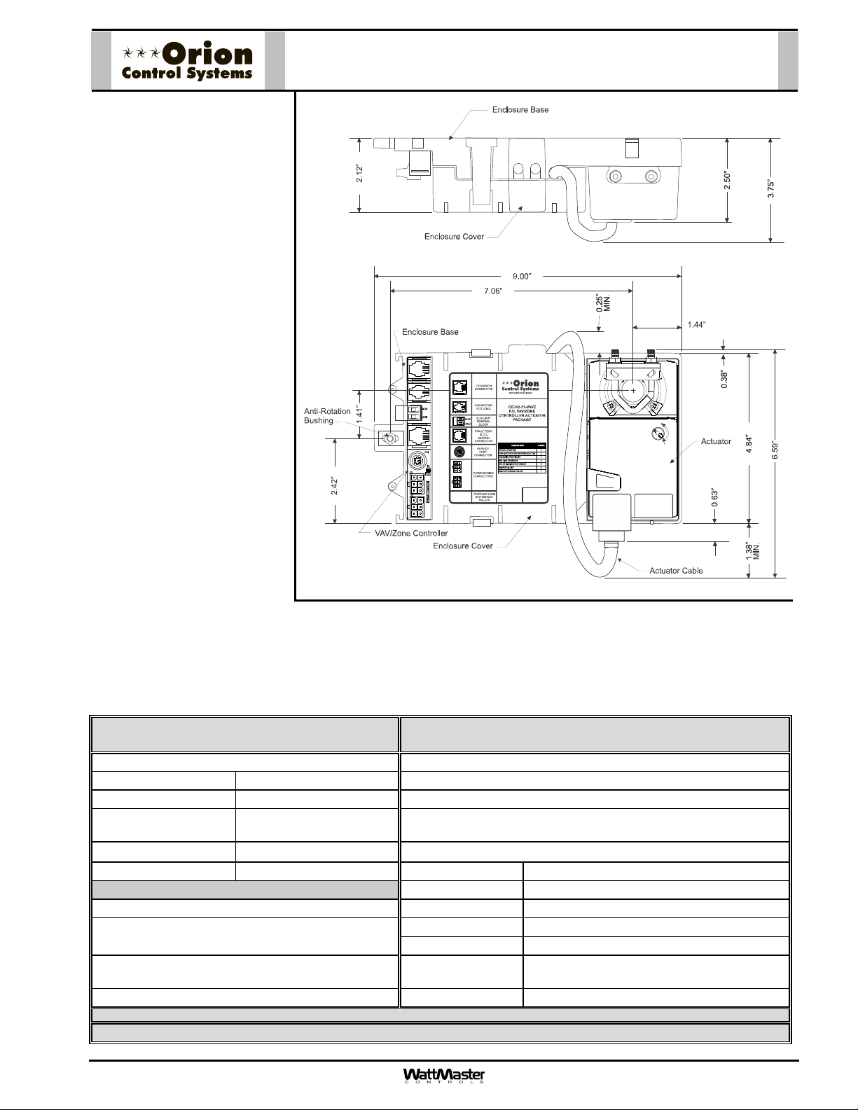
OE742-31-VAVZ VAV/Zone
Controller Actuator Package
Description
The OE742-31-VAVZ VAV/Zone
Controller Actuator Package with
Power/Comm connectors provides a new solution for zone
damper applications. The new
package includes a VAV/Zone
Actuator and a VAV/Zone Controller mounted in a plastic enclosure. An optional conduit cover is
also available that mounts over
the control terminals for installations requiring conduit connections. The VAV/Zone Controller
Actuator Package is designed for
left- or right-hand mounting on a
VAV Terminal unit. Each package
comes standard with a right-hand
label and the actuator positioned
for right-hand use. For left-hand
units, the actuator can be rotated
180 degrees by removing two
screws that secure it to the enclosure, rotating the damper actuator, and re-fastening the actuator
to the enclosure. A left-hand label
is also supplied that can be applied over the right-hand label for
left-hand applications.
Mounting
The VAV/Zone Actuator package
is very easy to mount on your
terminal unit. It is installed by
simply loosening the damper
shaft u-bolt on the actuator and sliding the entire Zone Controller Actuator Package Assembly over the terminal unit’s damper
shaft, tightening the actuator u-bolt around the damper shaft, and inserting a self-tapping screw into the anti-rotation bushing
located at the opposite end of the enclosure base. Detailed mounting and installation instructions are provided with each
package. A conduit enclosure is available as an option which provides conduit knockouts and encloses the electrical connections for applications where code requirements mandate conduit be used for low voltage electrical wiring.
Technical Data OE742-31-VAVZ
VAV/Zone Controller Actuator Package
Zone Controller: Outputs:
Supply Power 24 VAC (1) RJ-45 Cable Connection For Auxiliary Relay Board
Power Consumption 6 VA Maximum (1) RJ-45 Cable Connection To Damper Actuator
Operating Tempera-
ture
Operating Humidity 90% RH Non-Condensing
Communications RS-485 – 9600 Baud Programming Port Mini-DIN Jr. Port
Inputs:
(1) RJ-45 Cable Connection For Digital Temperature
Or Analog Temperature
(2) Auxiliary Terminals For Duct Temperature Sensor
(1) Molex Connector For Power/Comm In Airflow Ports Barbed Tube Fittings (PI Versions Only)
WattMaster reserves the right to change specifications without notice.
Three Year Warranty
Form: Orion-OE742-31-VAVZ-ZCAP-Sub-01C.doc Page 1 of 1
10F to 149F
Enclosure Material Fire Rated ABS Plastic
Zone Controller Factory Mounted Inside The Enclosure
Zone Actuator Factory Mounted To The Enclosure
Actuator Rating 35 in/lbs (6 ft2 Damper Area Max.)
Labeling Right Hand & Left Hand
(1) Molex Connector For Power/Comm Out
Features:
Page 2
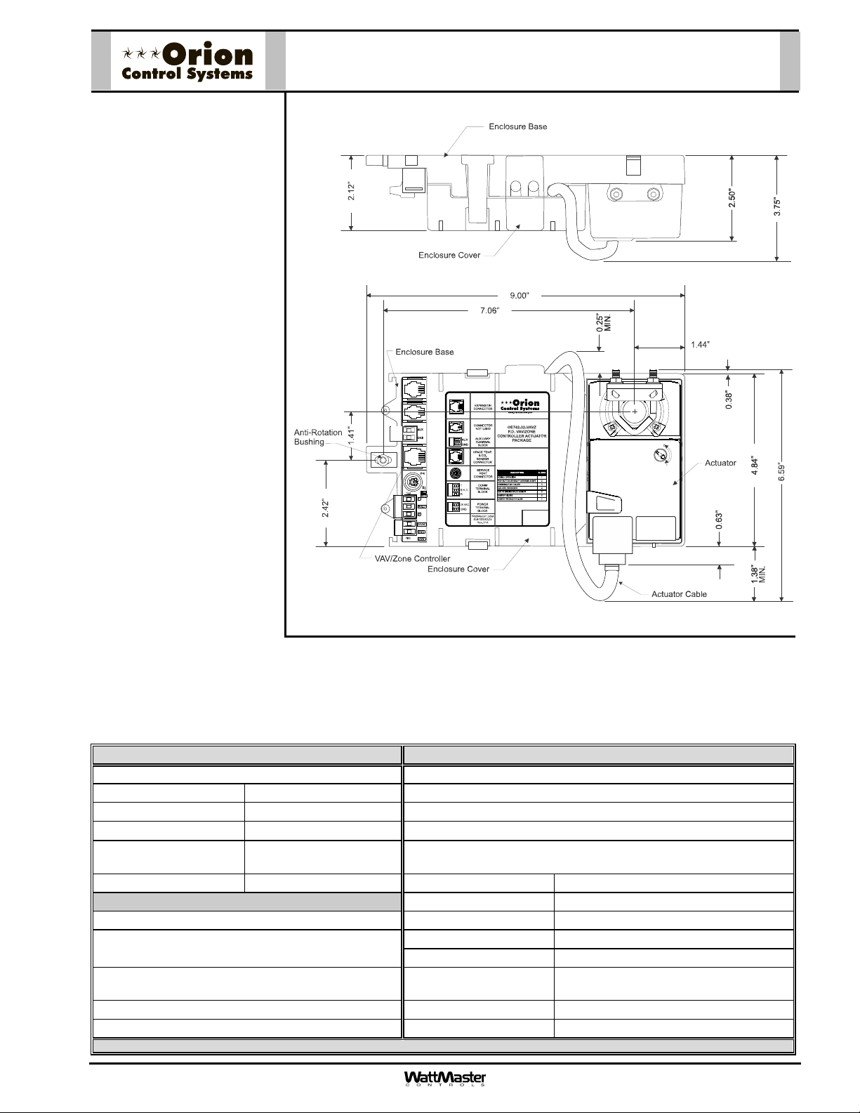
OE742-32-VAVZ VAV/Zone
Controller Actuator Package
Description
The OE742-32-VAVZ
VAV/Zone Controller Actuator
Package with Terminal Block
connectors provides a new solution for zone damper applications. The new package includes a VAV/Zone Actuator
and a VAV/Zone Controller
mounted in a plastic enclosure.
An optional conduit cover is
also available that mounts over
the control terminals for installations requiring conduit connections. The VAV/Zone Controller
Actuator Package is designed
for left- or right-hand mounting
on a VAV Terminal unit. Each
package comes standard with a
right-hand label and the actuator positioned for right-hand
use. For left-hand units, the
actuator can be rotated 180
degrees by removing two
screws that secure it to the enclosure, rotating the damper
actuator, and re-fastening the
actuator to the enclosure. A lefthand label is also supplied that
can be applied over the righthand label for left-hand applications.
Mounting
The VAV/Zone Actuator package is very easy to mount on
your terminal unit. It is installed
by simply loosening the damper shaft u-bolt on the actuator and sliding the entire Zone Controller Actuator Package Assembly
over the terminal unit’s damper shaft, tightening the actuator u-bolt around the damper shaft, and inserting a self-tapping
screw into the anti-rotation bushing located at the opposite end of the enclosure base. Detailed mounting and installation instructions are provided with each package. A conduit enclosure is available as an option which provides conduit knockouts
and encloses the electrical connections for applications where code requirements mandate conduit be used for low voltage
electrical wiring.
Technical Data OE742-32-VAVZ VAV/Zone Controller Actuator Package
Zone Controller: Outputs:
Supply Power 24 VAC (1) RJ-45 Cable Connection For Auxiliary Relay Board
Power Consumption 6 VA Maximum (1) RJ-45 Cable Connection To Damper Actuator
Operating Temperature
Operating Humidity 90% RH Non-
Communications RS-485 – 9600 Baud Programming Port Mini-DIN Jr. Port
Inputs:
(1) RJ-45 Cable Connection For Digital Temperature
Or Analog Temperature
(2) Auxiliary Terminals For Duct Temperature
Sensor
(1) Terminal Block Connector For Power In Airflow Ports Barbed Tube Fittings (PI Versions Only)
(1) Terminal Block Connector For Comm In
WattMaster reserves the right to change specifications without notice. Three Year Warranty
Form: Orion-OE742-32-VAVZ-ZCAP-Sub-01B.doc Page 1 of 1
10F to 149F
Condensing
Enclosure Material Fire Rated ABS Plastic
Zone Controller Factory Mounted Inside The Enclosure
Zone Actuator Factory Mounted To The Enclosure
Actuator Rating 35 in/lbs (6 ft2 Damper Area Max.)
Labeling Right Hand & Left Hand
Uses Same 3 Conductor Terminal Block as Comm Input
Features:
Page 3
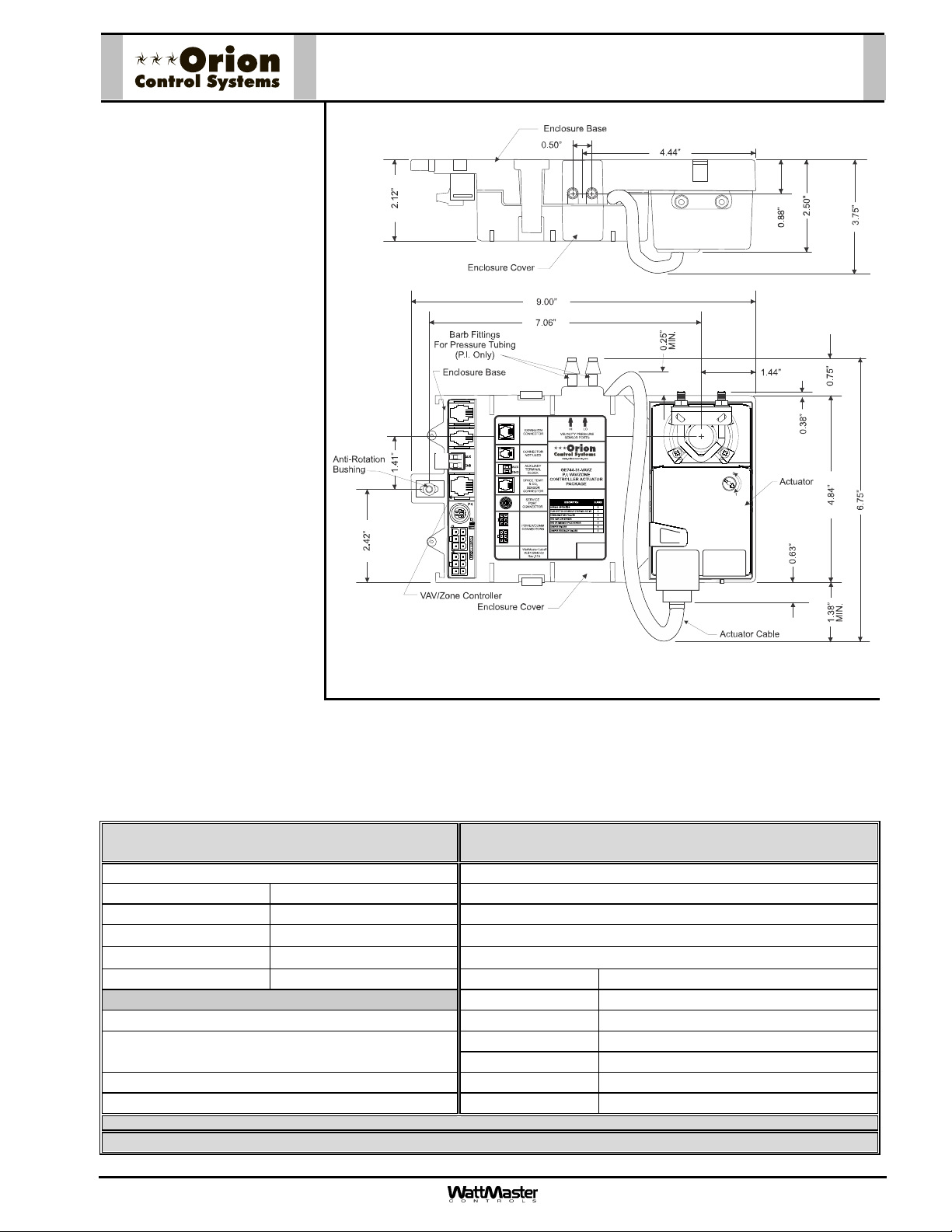
OE744-31-VAVZ VAV/Zone
Controller Actuator Package
Description
The OE744-31-VAVZ VAV/Zone
Controller Actuator Package with
Power/Comm connectors provides a new solution for zone
damper applications. The new
package includes a VAV/Zone
Actuator, a VAV/Zone Controller,
and an Airflow Sensor all mounted in a plastic enclosure. An optional conduit cover is also available that mounts over the control
terminals for installations requiring conduit connections. The
VAV/Zone Controller Actuator
Package is designed for left- or
right-hand mounting on a VAV
Terminal unit. Each package
comes standard with a right-hand
label and the actuator positioned
for right-hand use. For left-hand
units, the actuator can be rotated
180 degrees by removing two
screws that secure it to the enclosure, rotating the damper actuator, and re-fastening the actuator to the enclosure. A left-hand
label is also supplied that can be
applied over the right-hand label
for left-hand applications.
Mounting
The VAV/Zone Actuator package
is very easy to mount on your
terminal unit. It is installed by
simply loosening the damper
shaft u-bolt on the actuator and
sliding the entire Zone Controller Actuator Package Assembly over the terminal unit’s damper shaft, tightening the actuator ubolt around the damper shaft, and inserting a self-tapping screw into the anti-rotation bushing located at the opposite end of
the enclosure base. Detailed mounting and installation instructions are provided with each package. A conduit enclosure is
available as an option which provides conduit knockouts and encloses the electrical connections for applications where code
requirements mandate conduit be used for low voltage electrical wiring.
Technical Data OE744-31-VAVZ
VAV/Zone Controller Actuator Package
Zone Controller: Outputs:
Supply Power 24 VAC (1) RJ-45 Cable Connection For Auxiliary Relay Board
Power Consumption 6 VA Maximum (1) RJ-45 Cable Connection To Damper Actuator
Operating Temperature
Operating Humidity 90% RH Non-Condensing
Communications RS-485 – 9600 Baud Programming Port Mini-DIN Jr. Port
Inputs:
(1) RJ-45 Cable Connection For Digital Temperature
Or Analog Temperature
(2) Auxiliary Terminals For Duct Temperature Sensor Labeling Right Hand & Left Hand
(1) Molex Connector For Power/Comm In Airflow Ports Barbed Tube Fittings (PI Versions Only)
WattMaster reserves the right to change specifications without notice.
Three Year Warranty
Form: Orion-OE744-31-VAVZ-ZCAP-Sub-01C.doc Page 1 of 1
10F to 149F
Enclosure Material Fire Rated ABS Plastic
Zone Controller Factory Mounted Inside The Enclosure
Zone Actuator Factory Mounted To The Enclosure
Actuator Rating 35 in/lbs (6 ft2 Damper Area Max.)
(1) Molex Connector For Power/Comm Out
Features:
Page 4
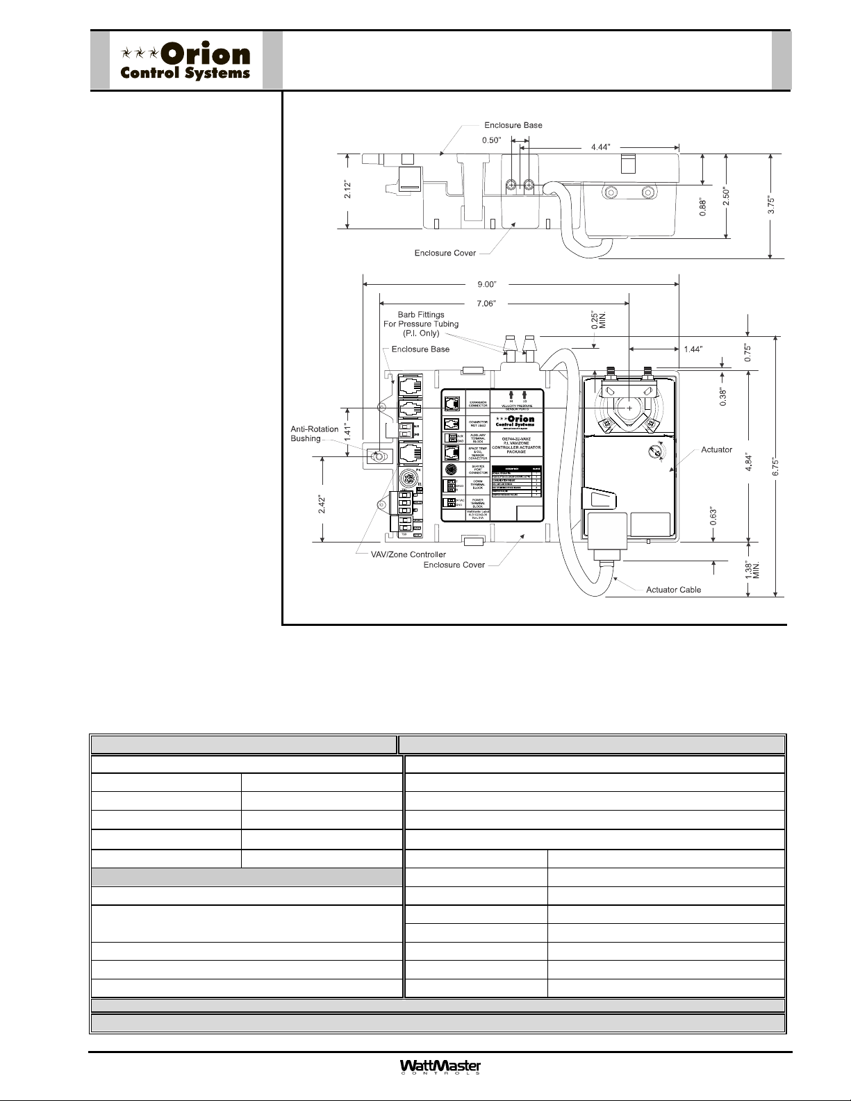
Description
The OE744-32-VAVZ
VAV/Zone Controller Actuator
Package with Terminal Block
connectors provides a new solution for zone damper applications. The new package includes a VAV/Zone Actuator, a
VAV/Zone Controller, and an
Airflow Sensor all mounted in a
plastic enclosure. An optional
conduit cover is also available
that mounts over the control
terminals for installations requiring conduit connections. The
VAV/Zone Controller Actuator
Package is designed for left- or
right-hand mounting on a VAV
Terminal unit. Each package
comes standard with a righthand label and the actuator
positioned for right-hand use.
For left-hand units, the actuator
can be rotated 180 degrees by
removing two screws that secure it to the enclosure, rotating
the damper actuator, and refastening the actuator to the
enclosure. A left-hand label is
also supplied that can be applied over the right-hand label
for left-hand applications.
OE744-32-VAVZ VAV/Zone
Controller Actuator Package
Mounting
The VAV/Zone Actuator package is very easy to mount on your terminal unit. It is installed by simply loosening the damper shaft u-bolt on the actuator and
sliding the entire Zone Controller Actuator Package Assembly over the terminal unit’s damper shaft, tightening the actuator ubolt around the damper shaft, and inserting a self-tapping screw into the anti-rotation bushing located at the opposite end of
the enclosure base. Detailed mounting and installation instructions are provided with each package. A conduit enclosure is
available as an option which provides conduit knockouts and encloses the electrical connections for applications where code
requirements mandate conduit be used for low voltage electrical wiring.
Technical Data OE744-32-VAVZ VAV/Zone Controller Actuator Package
Zone Controller: Outputs:
Supply Power 24 VAC (1) RJ-45 Cable Connection For Auxiliary Relay Board
Power Consumption 6 VA Maximum (1) RJ-45 Cable Connection To Damper Actuator
Operating Temperature
Operating Humidity 90% RH Non-Condensing
Communications RS-485 – 9600 Baud Programming Port Mini-DIN Jr. Port
Inputs:
(1) RJ-45 Cable Connection For Digital Temperature
Or Analog Temperature
(2) Auxiliary Terminals For Duct Temperature Sensor Labeling Right Hand & Left Hand
(1) Terminal Block Connector For Power In Airflow Ports Barbed Tube Fittings (PI Versions Only)
(1) Terminal Block Connector For Comm In
WattMaster reserves the right to change specifications without notice.
Three Year Warranty
10F to 149F
Enclosure Material Fire Rated ABS Plastic
Zone Controller Factory Mounted Inside The Enclosure
Zone Actuator Factory Mounted To The Enclosure
Actuator Rating 35 in/lbs (6 ft2 Damper Area Max.)
Form: Orion-OE744-32-VAVZ-ZCAP-Sub-01B.doc Page 1 of 1
Uses Same 3 Conductor Terminal Block as Comm Input
Features:
Page 5
Description
The OE325-01 4 Relay with Analog
Output Expansion board is used in
conjunction with the OE742-31VAVZ, OE742-32-VAVZ, OE74431-VAVZ, OE744-32-VAVZ
VAV/Zone Controller Actuator
Packages, the OE736-01, OE73602 Rectangular Damper Kits,the
OE520-XX-M, OE520-XX-T,
OE521-XX-M, OE521-XX-M Round
Zone Damper Assemblies. It
allows for control of fans, including
series and parallel flow fan
terminal units and/or heat. The
OE325-01 Analog Output
Expansion board provides 4 relay
outputs for pilot duty switching
control, (1 fan, 2 heat and 1
auxiliary) relay output and 1 Analog
output for control of a 0-10V
modulating hot water valve or SCR
controlled electric heating coil.
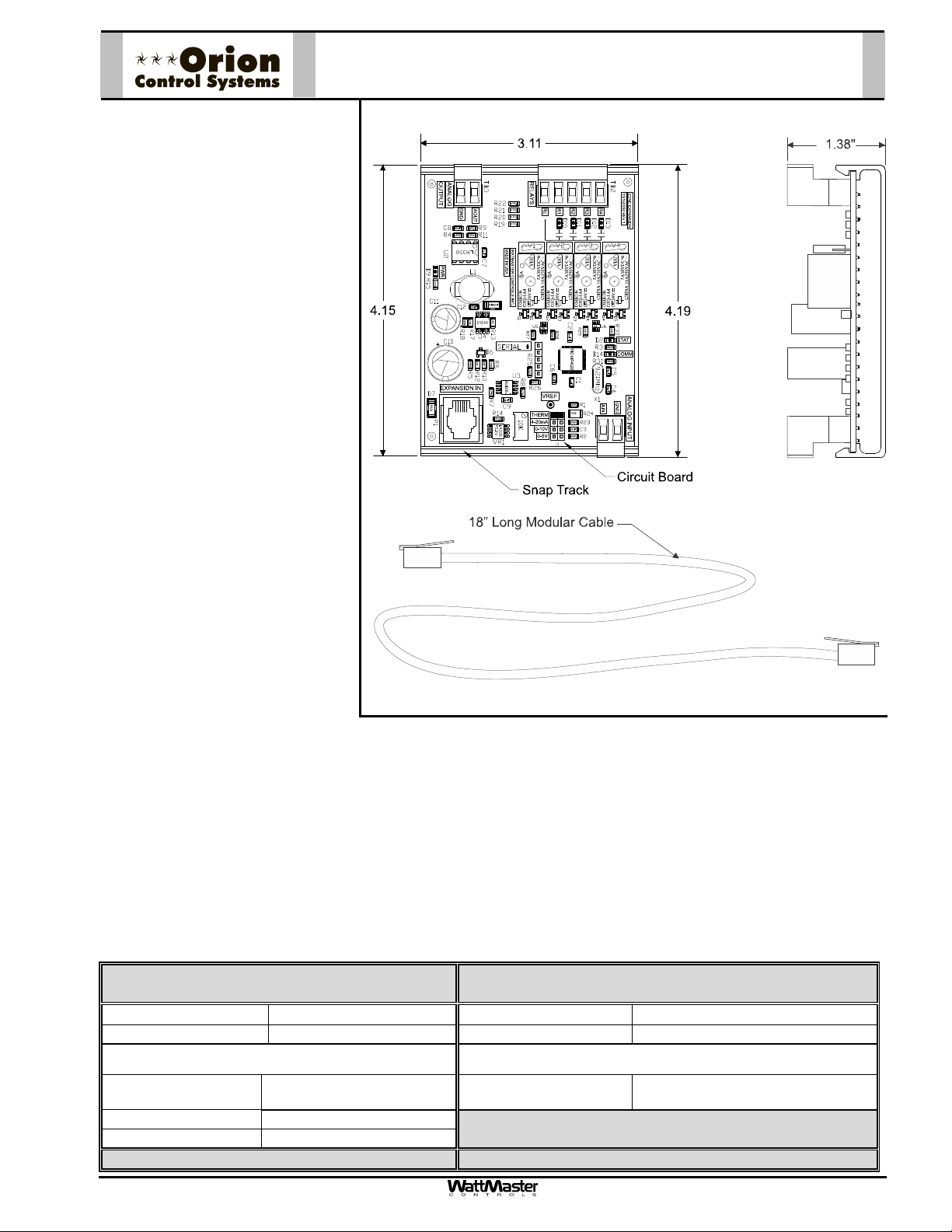
The OE325-01 4 Relay W/ Analog
Output Expansion board connects
to the VAV/Zone Controller board
by means of a 18” long modular
cable provided with the board.
Power is supplied to the board by
means of this modular cable.
Screw terminals are provided for
connection of field wiring to the
relay and analog outputs.
The relay outputs are N.O. contacts with one common terminal. All outputs and the relay common are electrically
isolated from all other circuitry on the board. All relay outputs are supplied with transient suppression devices
across each set of contacts to reduce EMI and arcing. The relay output contacts are rated for pilot duty control of
a maximum of 2 Amps @ 24 VAC or 24 VDC. The analog output provides a 0 – 10 VDC modulating signal output
into a 1k Ohm minimum load.
OE325-01 - 4 Relay W/ Analog Output
Expansion Board
Mounting
The OE325-01 4 Relay W/ Analog Output Expansion Board is supplied mounted on a plastic snap track channel.
The snap track channel has two mounting holes which are used to field mount the board with the provided
screws. The board should be mounted in close proximity to the VAVZ Zone Controller board to allow for
connection of the modular cable.
Technical Data OE325-01 4 Relay W/ Analog
Output Expansion board
Operating Temp
Weight 4 oz Connection to Controller: Modular Cable
10F to 149F
Operating Humidity 90% RH Non-Condensing
Outputs: Inputs:
Analog Output
Qty & Rating
Relay Output Qty. 4 – Electrically Isolated
Relay Contact Rating 2 Amp @ 24 VAC
Three Year Warranty
Form: ORION-OE325-01-4RelayW-AnalogOutputExpBrd-1B.doc Page 1 of 1
(1) 0-10 VDC @ 1k Ohm
Minimum load
Analog Input Application Specific
Universal Input
WattMaster reserves the right to change specifications without notice
Page 6
Description
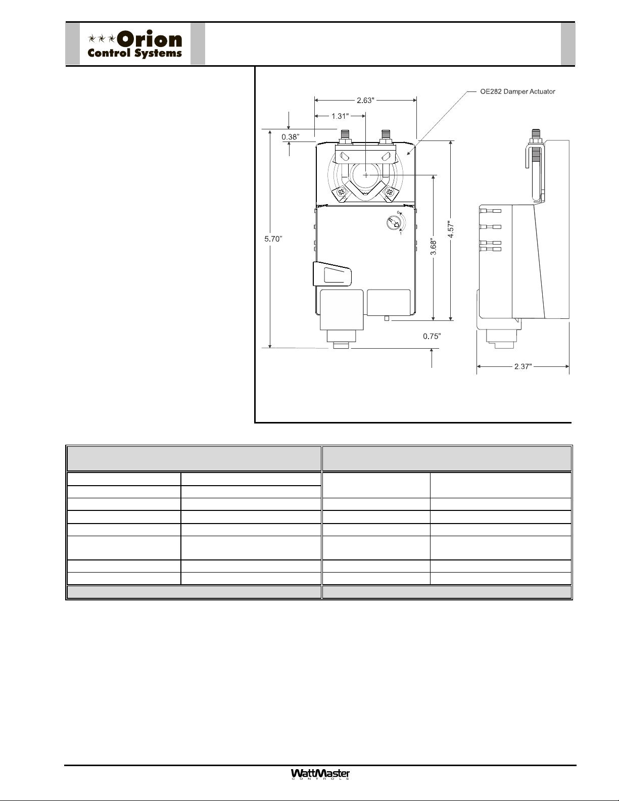
The Orion OE282 Damper Actuator is
a shaft mounted, floating point control
actuator. Actuators are 24VAC/24VDC
with a 10K ohm feedback signal for position monitoring. Wiring connection to
the actuator is by means of a modular
phone cable connector located on the
actuator cover. The actuator is rated for
35 in-lb of torque. All actuators are
electronically protected against overload. The angle of rotation is mechanically limited to 95. When the end position of the actuator or damper is
reached, the actuator automatically
stops. For adjustment purposes, the
gears can be manually disengaged by
pushing the manual override button on
the actuator cover.
OE282 - Damper Actuator
Applications
The OE282 Damper Actuator is used to
provide control of air volume dampers
in an Orion VAV or zoning systems.
When used in VAV and Zoning applications it is typically used in conjunction
with an OE324-00-VAVZ Zone controller board.
Technical Data OE282
Power Supply
Life Cycle Rating 2.5 Million Cycles with Mechanical Stops
Power Consumption 3 VA Maximum Power Connection RJ-11 Modular Jack
Operating Temp
Operating Humidity 5 to 95% RH Non-Condensing Quality Standard ISO 9001
Overload Protection
Feedback Signal 10K ohm 1W Potentiometer Torque Minimum 35 in-lb
Running Time 80-110 Seconds. Weight 1.2 lb.
Three Year Warranty WattMaster reserves the right to change specifications without notice
24VAC 20% 50/60HZ
-22F to 122F
Electronic Throughout 0 to 95
Rotation
Angle of Rotation
Servicing Maintenance Free
Agency Listings UL873 listed
Damper Actuator
Max. 95, Adjustable
CSA 4813 02 Certified
Form: ORION-OE282-ProportionalDamper Actuator-1C.doc Page 1 of 1
Page 7
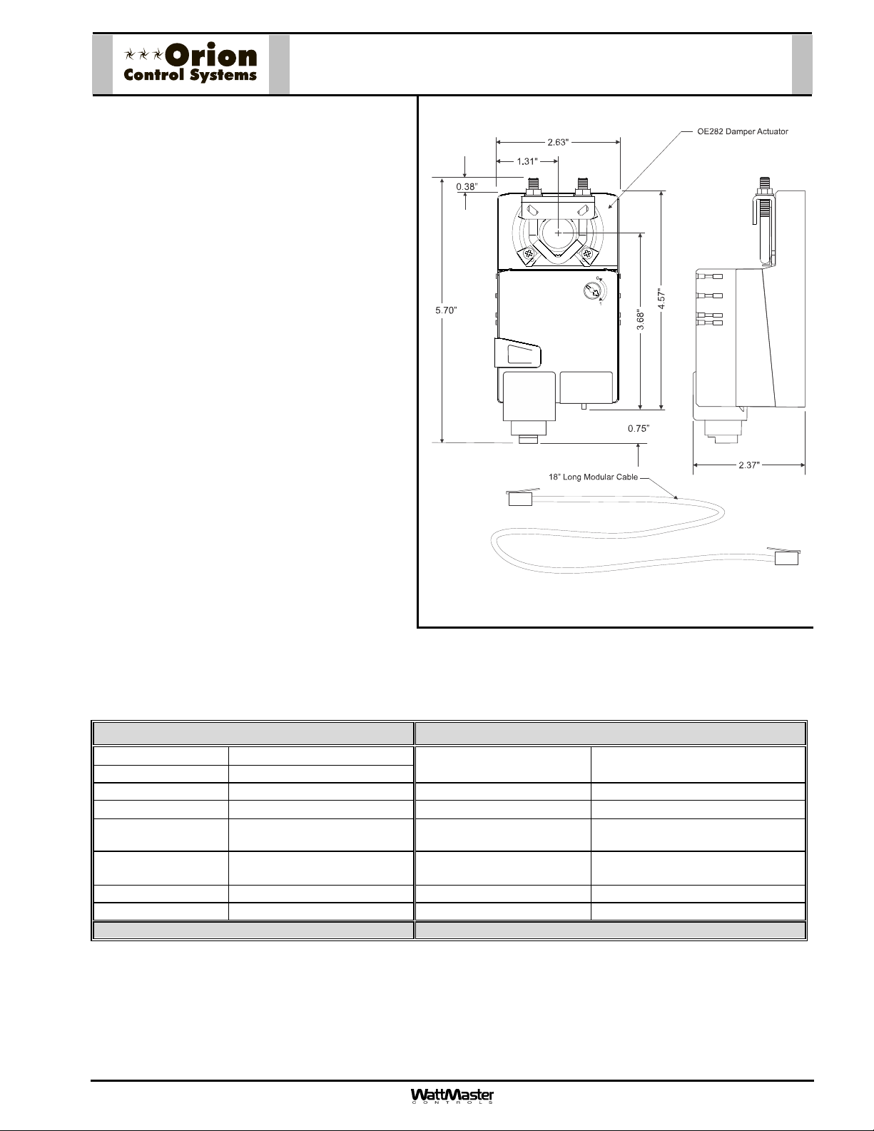
Description
The OE282 Damper Actuator is a shaft mounted,
floating point control actuator. Actuators are
24VAC/24VDC with a 10K ohm feedback signal
for position monitoring. Wiring connection to the
actuator is by means of a modular phone cable
connector located on the actuator cover. The
actuator is rated for 45 in-lb of torque. All
actuators are electronically protected against
overload. The angle of rotation is mechanically
limited to 95. When the end position of the
actuator or damper is reached, the actuator
automatically stops. For adjustment purposes,
the gears can be manually disengaged by
pushing the manual override button on the
actuator cover.
Zone Damper Actuator
OE282-01
Applications
The OE282 Damper Actuator is used to provide
control of air volume dampers in an VAV or
Zoning system.
When used in VAV and Zoning applications it is
normally factory mounted in the OE742-31VAVZ, OE742-32-VAVZ. P.D. VAV/Zone
Controller Actuator Packages or the OE744-31VAVZ, OE744-32-VAVZ. P.I. VAV/Zone
Controller Actuator Packages.
It is also a component of the OE282-03 Slaved
VAV/Zone Damper Kit. This kit allows multiple
dampers (up to 2 total besides the master) to be
connected to a master OE742-31-vVAVZ, OE742-32-VAVZ P.D. Zone/VAV Controller Actuator Package or
OE744-31-VAVZ, OE744-32-VAVZ P.I. Zone/VAV Controller Actuator Packages. The OE282-03 Kit is typically
used when larger CFM requirements dictate multiple dampers be used.
Technical Data OE282-01 Damper Actuator
Power Supply
Life Cycle Rating 2.5 Million Cycles with Mechanical Stops
Power Consumption 3 VA Maximum Power Connection RJ-11 Modular Jack
Operating Temp
Operating Humidity 5 to 95% RH Non-
Overload Protection Electronic Throughout 0 to
Feedback Signal 10K ohm 1W Potentiometer Torque Minimum 45 in-lb
Running Time 80-110 Seconds. Weight 1.2 lb.
Three Year Warranty
Form: ORION-OE282-01ZoneDmprAct-Sub-01A.doc Page 1 of 1
24VAC 20% 50/60HZ
-22F to 122F
Condensing
95 Rotation
Angle of Rotation
Servicing Maintenance Free
Quality Standard ISO 9001
Agency Listings UL873 listed
WattMaster reserves the right to change specifications without notice
Max. 95, Adjustable
CSA 4813 02 Certified
Page 8
Description
The OE520-XX-M Round Pressure
Dependent Zone Damper Assembly with
modular connectors consists of a round
air damper and Zone Controller Actuator
Package with modular wiring connectors.
An optional Zone Controller Expansion
Module (OE325-01) is available for
control of reheat, heat and/or control of
series or parallel flow fan terminal units.
The Zone Controller board is
microprocessor based and communicates
with the HVAC unit controller on the Orion
network communications loop. The Zone
Controller monitors the space
temperature and allocates the proper
airflow into its assigned space to achieve
the desired comfort and ventilation levels.
Pressure Dependent Zone Dampers are
used in air conditioning systems that do
not require pressure independent airflow
control. If your system requires pressure
independent control of the airflow, see the
“OE521-XX-M Round Pressure
Independent Zone Damper” submittal sheet for the correct specifications. All dampers are tested for performance
in accordance with AMCA 500D standards.
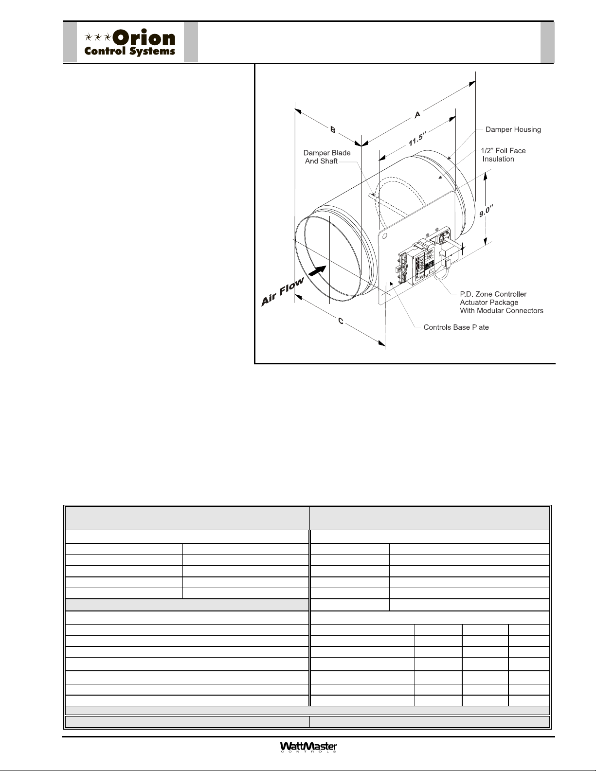
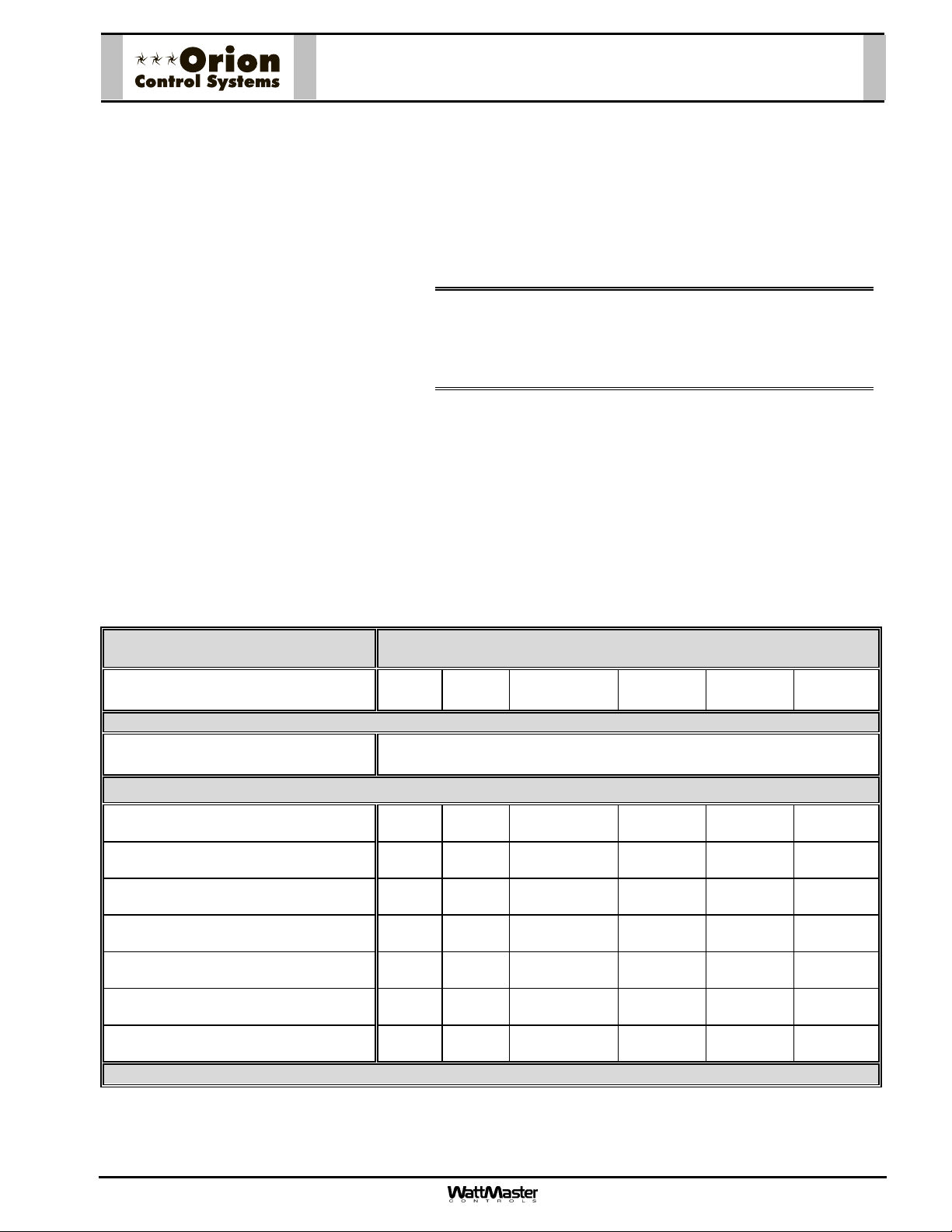
OE520-XX-M Round P.D. Zone Damper
Assembly W/ Modular Connectors
Mounting
The Zone Damper Assembly should be mounted according to standard duct installation practices with airflow
direction as shown in the illustration above. After installation of the Zone Damper in the ductwork, insulation
should be applied around any remaining un-insulated surface on the damper inlet and outlet. The Zone Damper
should be mounted so the control enclosure is positioned to the left or right side of the ductwork with the control
enclosure in a vertical plane. Do not mount the Zone Damper Assembly with the control enclosure on the top or
bottom of the ductwork. Adequate clearance should be maintained between the control panel and any
obstruction to allow for removal of the control panel cover and access to the controls.
Technical Data
Zone Damper Assembly W/ Modular Connectors
OE520-XX-M Round Pressure Dependent
Zone Controller: Air Damper Construction:
Supply Power 24 Volt AC Damper Body 20 Ga. Galv. Steel
Power Consumption 6 VA Maximum Damper Blade Round -18 Ga. Galv. Steel
Operating Temperature
Operating Humidity 90% RH Non-Condensing Damper Seal EPDM Rubber Gasket
Communications RS-485 - 9600 Baud Leakage < 20 CFM Per Sq. Ft. @ 4” SP
35F to 125F
Damper Bearings Stainless Steel
Insulation ½” Foil Faced Fiberglass
Inputs: Dimensions:
Room Temperature Sensor
Setpoint Adjustment OE510-06 (6”) 23.00 5.88 9.88
Actuator Position Feedback OE510-08 (8”) 23.00 7.88 12.13
Communication Connectors: Modular In & Out
Outputs:
Expansion Port for Auxiliary Relay Board OE510-14 (14”) 23.00 13.88 18.50
Actuator Port for Connection to Damper Actuator OE510-16 (16”) 23.00 15.88 20.56
WattMaster reserves the right to change specifications without notice
Three Year Warranty On Electronic Components One Year Warranty On Air Damper
Air Damper Model “A” “B” “C”
OE510-10 (10”) 23.00 9.88 14.31
OE510-12 (12”) 23.00 11.88 16.43
Form: Orion-OE520XX-M-RndDmpr-Sub-01G Page 1 of 2
Page 9
OE520-XX-M Round P.D. Zone Damper
Assembly W/ Modular Connectors
Zone Damper Sizing
Use a load program to determine the peak
load for each zone. These calculations will be
used to select VAV/Zone Damper sizes.
The Orion Systems utilize a typical low
pressure duct design. To reduce noise
problems, duct pressures should not exceed
1” W.C.
Primary trunk ducts used with Orion systems
should not be “undersized”. This is especially
true of “pressure dependent” systems. With
larger trunk ducts, it is easier to assure
relatively constant pressure to each Zone
Damper. Runs should be as short as
possible, and the trunk duct system kept as
symmetrical as possible to facilitate system
balancing. Wherever possible, run the trunk
ducts above corridors and locate the Zone
Dampers above corridors to reduce the noise
in the space and facilitate service of the
valves. Trunk ducts should be sized for no
more than 0.1” W.C. drop per 100 ft. of duct,
and a maximum duct velocity of 2000 FPM.
Zone Damper Selection Data
Zone Damper Round Duct Size
(Area Ft
Velocity Through VAV/Zone Damper
FPM
500
750
1000
1250
1500
1750
2000
2
)
WattMaster reserves the right to change specifications without notice
6”
(0.196)
98
(< 0.01)
147
(0.01)
196
(0.015)
245
(0.025)
294
(0.035)
343
(0.045)
392
(0.065)
Using the maximum acceptable velocity for a branch duct
(typically 1000-1500 FPM for minimal noise), find the smallest
Zone Damper that will deliver the required CFM as determined
by the load program. Locate the branch velocity used in the duct
design program in the left hand column of the Zone Damper
Selection Data table. Move across the table and find the Zone
Damper, which will provide the acceptable CFM to meet the zone
airflow requirements.
Note: Compare the Zone Damper size selected against the
duct size to determine if the next size up or down will
provide acceptable performance without requiring a
transition fitting.
Up to a maximum of two Slaved Zone Dampers may be slaved
together with the main Zone Damper for large zones. This design
should be reserved only for situations when it is not practical to
use a single Zone Damper. See the AZ-300-RS Round Slaved
Zone Damper submittal sheet for information regarding
application and selection of Round Slaved Zone Dampers.
OE520-XX-M Round Pressure Dependent
Zone Damper Assembly W/ Modular Connectors
8”
(0.349)
Airflow Through VAV/Zone Damper - CFM
(P
175
(< 0.01)
262
(0.01)
349
(0.015)
436
(0.02)
523
(0.035)
611
(0.035)
698
(0.043)
10”
(0.545)
inches W.C. w/ Damper Full Open)
S
273
(< 0.01)
409
(0.01)
545
(0.01)
681
(0.015)
818
(0.022)
954
(0.034)
1090
(0.040)
12”
(0.785)
393
(< 0.01)
589
(< 0.01)
785
(< 0.01)
981
(0.015)
1178
(0.020)
1374
(0.030)
1570
(0.040)
(1.069)
(< 0.01)
(< 0.01)
(< 0.01)
(0.015)
(0.030)
(0.040)
14”
535
802
1069
1336
1604
0.020)
1871
2138
16”
(1.396)
698
(< 0.01)
1047
(< 0.01)
1396
(< 0.01)
1745
(0.015)
2094
(0.020)
2443
(0.025)
2792
(0.030)
Form: Orion-OE520XX-M-RndDmpr-Sub-01G Page 2 of 2
Page 10
Description
The OE520-XX-T Round Pressure Dependent
Zone Damper Assembly with terminal
connectors consists of a round air damper
and Zone Controller Actuator Package with
terminal wiring connectors. An optional Zone
Controller Expansion Module (OE325-01) is
available for control of reheat, heat and/or
control of series or parallel flow fan terminal
units.
The Zone Controller board is microprocessor
based and communicates with the HVAC unit
controller on the Orion network
communications loop. The Zone Controller
monitors the space temperature and allocates
the proper airflow into its assigned space to
achieve the desired comfort and ventilation
levels.
Pressure Dependent Zone Dampers are used
in air conditioning systems that do not require
pressure independent airflow control. If your
system requires pressure independent control
of the airflow, see the “OE521-XX-T Round
Pressure Independent Zone Damper”
submittal sheet for the correct specifications. All dampers are tested for performance in accordance with AMCA
500D standards.
OE520-XX-T Round P.D. Zone Damper
Assembly W/ Terminal Connectors
Mounting
The Zone Damper Assembly should be mounted according to standard duct installation practices with airflow
direction as shown in the illustration above. After installation of the Zone Damper in the ductwork, insulation
should be applied around any remaining un-insulated surface on the damper inlet and outlet. The Zone Damper
should be mounted so the control enclosure is positioned to the left or right side of the ductwork with the control
enclosure in a vertical plane. Do not mount the Zone Damper Assembly with the control enclosure on the top or
bottom of the ductwork. Adequate clearance should be maintained between the control panel and any
obstruction to allow for removal of the control panel cover and access to the controls.
Technical Data
Zone Damper Assembly W/ Terminal Connectors
OE520-XX-T Round Pressure Dependent
Zone Controller: Air Damper Construction:
Supply Power 24 Volt AC Damper Body 20 Ga. Galv. Steel
Power Consumption 6 VA Maximum Damper Blade Round -18 Ga. Galv. Steel
Operating Temperature
Operating Humidity 90% RH Non-Condensing Damper Seal EPDM Rubber Gasket
Communications RS-485 - 9600 Baud Leakage < 20 CFM Per Sq. Ft. @ 4” SP
35F to 125F
Damper Bearings Stainless Steel
Insulation ½” Foil Faced Fiberglass
Inputs: Dimensions:
Room Temperature Sensor
Setpoint Adjustment OE510-06 (6”) 23.00 5.88 9.88
Actuator Position Feedback OE510-08 (8”) 23.00 7.88 12.13
Communication Connectors: Terminals In & Out
Outputs:
Expansion Port for Auxiliary Relay Board OE510-14 (14”) 23.00 13.88 18.50
Actuator Port for Connection to Damper Actuator OE510-16 (16”) 23.00 15.88 20.56
WattMaster reserves the right to change specifications without notice
Three Year Warranty On Electronic Components One Year Warranty On Air Damper
Air Damper Model “A” “B” “C”
OE510-10 (10”) 23.00 9.88 14.31
OE510-12 (12”) 23.00 11.88 16.43
Form: Orion-OE520XX-T-RndDmpr-Sub-01G Page 1 of 2
Page 11

OE520-XX-T Round P.D. Zone Damper
Assembly W/ Terminal Connectors
VAV/Zone Damper Sizing
Use a load program to determine the peak
load for each zone. These calculations will be
used to select Zone Damper sizes.
The Orion Systems utilize a typical low
pressure duct design. To reduce noise
problems, duct pressures should not exceed
1” W.C.
Primary trunk ducts used with Orion systems
should not be “undersized”. This is especially
true of “pressure dependent” systems. With
larger trunk ducts, it is easier to assure
relatively constant pressure to each Zone
Damper. Runs should be as short as
possible, and the trunk duct system kept as
symmetrical as possible to facilitate system
balancing. Wherever possible, run the trunk
ducts above corridors and locate the Zone
Dampers above corridors to reduce the noise
in the space and facilitate service of the
valves. Trunk ducts should be sized for no
more than 0.1” W.C. drop per 100 ft. of duct,
and a maximum duct velocity of 2000 FPM.
Zone Damper Selection Data
Zone Damper Round Duct Size
(Area Ft
Velocity Through VAV/Zone Damper
FPM
500
750
1000
1250
1500
1750
2000
2
)
WattMaster reserves the right to change specifications without notice
6”
(0.196)
98
(< 0.01)
147
(0.01)
196
(0.015)
245
(0.025)
294
(0.035)
343
(0.045)
392
(0.065)
Using the maximum acceptable velocity for a branch duct
(typically 1000-1500 FPM for minimal noise), find the smallest
Zone Damper that will deliver the required CFM as determined
by the load program. Locate the branch velocity used in the
duct design program in the left hand column of the Zone
Damper Selection Data table. Move across the table and find
the Zone Damper, which will provide the acceptable CFM to
meet the zone airflow requirements.
Note: Compare the Zone Damper size selected against
the duct size to determine if the next size up or
down will provide acceptable performance without
requiring a transition fitting.
Up to a maximum of two Slaved Zone Dampers may be slaved
together with the main Zone Damper for large zones. This
design should be reserved only for situations when it is not
practical to use a single Zone Damper. See the AZ-300-RS
Round Slaved Zone Damper submittal sheet for information
regarding application and selection of Round Slaved Zone
Dampers.
OE520-XX-T Round Pressure Dependent
Zone Damper Assembly W/ Terminal Connectors
8”
(0.349)
Airflow Through VAV/Zone Damper - CFM
(P
175
(< 0.01)
262
(0.01)
349
(0.015)
436
(0.02)
523
(0.035)
611
(0.035)
698
(0.043)
10”
(0.545)
inches W.C. w/ Damper Full Open)
S
273
(< 0.01)
409
(0.01)
545
(0.01)
681
(0.015)
818
(0.022)
954
(0.034)
1090
(0.040)
12”
(0.785)
393
(< 0.01)
589
(< 0.01)
785
(< 0.01)
981
(0.015)
1178
(0.020)
1374
(0.030)
1570
(0.040)
(1.069)
(< 0.01)
(< 0.01)
(< 0.01)
(0.015)
0.020)
(0.030)
(0.040)
14”
535
802
1069
1336
1604
1871
2138
16”
(1.396)
698
(< 0.01)
1047
(< 0.01)
1396
(< 0.01)
1745
(0.015)
2094
(0.020)
2443
(0.025)
2792
(0.030)
Form: Orion-OE520XX-T-RndDmpr-Sub-01G Page 2 of 2
Page 12
Description
The OE521-XX-M Round Pressure
Independent Zone Damper Assembly with
modular connectors consists of a round
air damper with air flow pickup cross and
a Zone Controller Actuator Package
(including air flow sensor) with modular
connectors. An optional Zone Controller
Expansion Module (OE325-01) is
available for control of reheat, heat and/or
control of series or parallel flow fan
terminal units.
The Zone Controller board is
microprocessor based and communicates
with the HVAC unit controller on the Orion
network communications loop. The Zone
Controller monitors the space
temperature and allocates the proper
airflow into its assigned space to achieve
the desired comfort and ventilation levels.
Pressure Independent Zone Dampers are
used in air conditioning systems require
pressure independent airflow control. If
your system requires pressure dependent
control of the airflow, see the “OE520-XX-M Round Pressure Dependent Zone Damper” submittal sheet for the
correct specifications. All dampers are tested for performance in accordance with AMCA 500D standards.
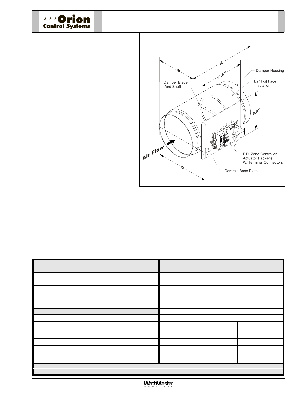
OE521-XX-M Round P.I. Zone Damper
Assembly W/ Modular Connectors
Mounting
The Zone Damper Assembly should be mounted according to standard duct installation practices with airflow
direction as shown in the illustration above. After installation of the Zone Damper in the ductwork, insulation
should be applied around any remaining un-insulated surface on the damper inlet and outlet. The Zone Damper
should be mounted so the control enclosure is positioned to the left or right side of the ductwork with the control
enclosure in a vertical plane. Do not mount the Zone Damper Assembly with the control enclosure on the top or
bottom of the ductwork. Adequate clearance should be maintained between the control panel and any
obstruction to allow for removal of the control panel cover and access to the controls.
Technical Data
OE521-XX-M Round Pressure Independent
Zone Damper Assembly W/ Modular Connectors
Zone Controller: Air Damper Construction:
Supply Power 24 Volt AC Damper Body 20 Ga. Galv. Steel
Power Consumption 6 VA Maximum Damper Blade Round -18 Ga. Galv. Steel
Operating Temperature
Operating Humidity 90% RH Non-Condensing Damper Seal EPDM Rubber Gasket
Communications RS-485 - 9600 Baud Leakage < 20 CFM Per Sq. Ft. @ 4” SP
35F to 125F
Inputs:
Air Flow Sensor
Room Temperature Sensor
Setpoint Adjustment OE510-06 (6”) 23.00 5.88 9.88
Actuator Position Feedback OE510-08 (8”) 23.00 7.88 12.13
Communication Connectors: Modular In & Out
Outputs:
Expansion Port for Auxiliary Relay Board OE510-14 (14”) 23.00 13.88 18.50
Actuator Port for Connection to Damper Actuator OE510-16 (16”) 23.00 15.88 20.56
WattMaster reserves the right to change specifications without notice
Three Year Warranty On Electronic Components One Year Warranty On Air Damper
Damper Bearings Stainless Steel
Insulation ½” Foil Faced Fiberglass
Dimensions:
Air Damper Model “A” “B” “C”
OE510-10 (10”) 23.00 9.88 14.31
OE510-12 (12”) 23.00 11.88 16.43
FormOrion-OE521XX-M-RndDmpr-Sub-01G Page 1 of 2
Page 13

A
OE521-XX-M Round P.I. Zone Damper
Assembly W/ Modular Connectors
Zone Damper Sizing
Use a load program to determine the peak
load for each zone. These calculations will be
used to select Zone Damper sizes.
The Orion Systems utilize a typical low
pressure duct design. To reduce noise
problems, duct pressures should not exceed
1” W.C.
Primary trunk ducts used with Orion systems
should not be “undersized”. This is especially
true of “pressure dependent” systems. With
larger trunk ducts, it is easier to assure
relatively constant pressure to each Zone
Damper. Runs should be as short as
possible, and the trunk duct system kept as
symmetrical as possible to facilitate system
balancing. Wherever possible, run the trunk
ducts above corridors and locate the Zone
Dampers above corridors to reduce the noise
in the space and facilitate service of the
dampers. Trunk ducts should be sized for no
more than 0.1” W.C. drop per 100 ft. of duct,
and a maximum duct velocity of 2000 FPM.
Using the maximum acceptable velocity for a branch duct
(typically 1000-1500 FPM for minimal noise), find the smallest
Zone Damper that will deliver the required CFM as determined
by the load program. Locate the branch velocity used in the
duct design program in the left hand column of the Zone
Damper Selection Data table. Move across the table and find
the Zone Damper, which will provide the acceptable CFM to
meet the zone airflow requirements.
Note: Compare the Zone Damper size selected against
the duct size to determine if the next size up or
down will provide acceptable performance without
requiring a transition fitting.
Pressure Independent Zone Dampers may not be slaved
together with Slaved-Zone Damper Assemblies. If more than
one damper is required for a zone, all dampers must be
selected as pressure dependent. See the Pressure Dependent
Zone Damper submittal sheet and Slaved-Zone Damper
submittal sheets for selection of master/slave damper
configurations.
Zone Damper Selection Data
Zone Damper Round Duct Size
(Area Ft
CFM @ 1” Velocity Pressure
(Air Flow Probe “K” Factor)
Velocity Through VAV/Zone Damper
FPM
500
750
1000
1250
1500
1750
2000
2
)
WattMaster reserves the right to change specifications without notice
OE521-XX-M Round Pressure Independent Zone Damper
ssembly W/ Modular Connectors
6”
(0.196)
448 904 1436 1891 3015 3839
8”
(0.349)
Airflow Through VAV/Zone Damper - CFM
(P
10”
(0.545)
inches W.C. w/ Damper Full Open)
S
12”
(0.785)
14”
(1.069)
16”
(1.396)
98
(< 0.01)
147
(0.01)
196
(0.015)
245
(0.025)
294
(0.035)
343
(0.045)
392
(0.065)
175
(< 0.01)
262
(0.01)
349
(0.015)
436
(0.02)
523
(0.035)
611
(0.035)
698
(0.043)
273
(< 0.01)
409
(0.01)
545
(0.01)
681
(0.015)
818
(0.022)
954
(0.034)
1090
(0.040)
393
(< 0.01)
589
(< 0.01)
785
(< 0.01)
981
(0.015)
1178
(0.020)
1374
(0.030)
1570
(0.040)
535
(< 0.01)
802
(< 0.01)
1069
(< 0.01)
1336
(0.015)
1604
0.020)
1871
(0.030)
2138
(0.040)
698
(< 0.01)
1047
(< 0.01)
1396
(< 0.01)
1745
(0.015)
2094
(0.020)
2443
(0.025)
2792
(0.030)
FormOrion-OE521XX-M-RndDmpr-Sub-01G Page 2 of 2
Page 14

Description
The OE521-XX-T Round Pressure
Independent Zone Damper Assembly with
terminal connectors consists of a round
air damper with air flow pickup cross and
a Zone Controller Actuator Package
(including air flow sensor) with terminal
connectors. An optional Zone Controller
Expansion Module (OE325-01) is
available for control of reheat, heat and/or
control of series or parallel flow fan
terminal units.
The Zone Controller board is
microprocessor based and communicates
with the HVAC unit controller on the Orion
network communications loop. The Zone
Controller monitors the space
temperature and allocates the proper
airflow into its assigned space to achieve
the desired comfort and ventilation levels.
Pressure Independent Zone Dampers are
used in air conditioning systems require
pressure independent airflow control. If
your system requires pressure dependent
control of the airflow, see the “OE520-XX-T Round Pressure Dependent Zone Damper” submittal sheet for the
correct specifications. All dampers are tested for performance in accordance with AMCA 500D standards.
OE521-XX-T Round P.I. Zone Damper
Assembly W/ Terminal Connectors
Mounting
The Zone Damper Assembly should be mounted according to standard duct installation practices with airflow
direction as shown in the illustration above. After installation of the Zone Damper in the ductwork, insulation
should be applied around any remaining un-insulated surface on the damper inlet and outlet. The Zone Damper
should be mounted so the control enclosure is positioned to the left or right side of the ductwork with the control
enclosure in a vertical plane. Do not mount the Zone Damper Assembly with the control enclosure on the top or
bottom of the ductwork. Adequate clearance should be maintained between the control panel and any
obstruction to allow for removal of the control panel cover and access to the controls.
Technical Data
Zone Damper Assembly W/ Terminal Connectors
OE521-XX-T Round Pressure Independent
Zone Controller: Air Damper Construction:
Supply Power 24 Volt AC Damper Body 20 Ga. Galv. Steel
Power Consumption 6 VA Maximum Damper Blade Round -18 Ga. Galv. Steel
Operating Temperature
Operating Humidity 90% RH Non-Condensing Damper Seal EPDM Rubber Gasket
Communications RS-485 - 9600 Baud Leakage < 20 CFM Per Sq. Ft. @ 4” SP
35F to 125F
Inputs:
Air Flow Sensor
Room Temperature Sensor
Setpoint Adjustment OE510-06 (6”) 23.00 5.88 9.88
Actuator Position Feedback OE510-08 (8”) 23.00 7.88 12.13
Communication Connectors: Terminals In & Out
Outputs:
Expansion Port for Auxiliary Relay Board OE510-14 (14”) 23.00 13.88 18.50
Actuator Port for Connection to Damper Actuator OE510-16 (16”) 23.00 15.88 20.56
WattMaster reserves the right to change specifications without notice
Three Year Warranty On Electronic Components One Year Warranty On Air Damper
Damper Bearings Stainless Steel
Insulation ½” Foil Faced Fiberglass
Dimensions:
Air Damper Model “A” “B” “C”
OE510-10 (10”) 23.00 9.88 14.31
OE510-12 (12”) 23.00 11.88 16.43
Form: Orion-OE521XX-T-RndDmpr-Sub-01G Page 1 of 2
Page 15

OE521-XX-T Round P.I. Zone Damper
Assembly W/ Terminal Connectors
Zone Damper Sizing
Use a load program to determine the peak
load for each zone. These calculations will be
used to select Zone Damper sizes.
The Orion Systems utilize a typical low
pressure duct design. To reduce noise
problems, duct pressures should not exceed
1” W.C.
Primary trunk ducts used with Orion systems
should not be “undersized”. This is especially
true of “pressure dependent” systems. With
larger trunk ducts, it is easier to assure
relatively constant pressure to each Zone
Damper. Runs should be as short as
possible, and the trunk duct system kept as
symmetrical as possible to facilitate system
balancing. Wherever possible, run the trunk
ducts above corridors and locate the Zone
Dampers above corridors to reduce the noise
in the space and facilitate service of the
valves. Trunk ducts should be sized for no
more than 0.1” W.C. drop per 100 ft. of duct,
and a maximum duct velocity of 2000 FPM.
Zone Damper Selection Data
Zone Damper Round Duct Size
(Area Ft
2
)
6”
(0.196)
Using the maximum acceptable velocity for a branch duct
(typically 1000-1500 FPM for minimal noise), find the smallest
Zone Damper that will deliver the required CFM as determined
by the load program. Locate the branch velocity used in the
duct design program in the left hand column of the Zone
Damper Selection Data table. Move across the table and find
the Zone Damper, which will provide the acceptable CFM to
meet the zone airflow requirements.
Note: Compare the Zone Damper size selected against
the duct size to determine if the next size up or
down will provide acceptable performance without
requiring a transition fitting.
Pressure Independent Zone Dampers may not be slaved
together with Slaved-Zone Damper Assemblies. If more than
one damper is required for a zone, all dampers must be
selected as pressure dependent. See the Pressure Dependent
Zone Damper submittal sheet and Slaved-Zone Damper
submittal sheets for selection of master/slave damper
configurations.
OE521-XX-T Round Pressure Independent
Zone Damper Assembly W/ Terminal Connectors
8”
(0.349)
10”
(0.545)
12”
(0.785)
14”
(1.069)
16”
(1.396)
CFM @ 1” Velocity Pressure
(Air Flow Probe “K” Factor)
Velocity Through VAV/Zone Damper
FPM
500
750
1000
1250
1500
1750
2000
WattMaster reserves the right to change specifications without notice
448 904 1436 1891 3015 3839
Airflow Through VAV/Zone Damper - CFM
(P
inches W.C. w/ Damper Full Open)
S
98
(< 0.01)
147
(0.01)
196
(0.015)
245
(0.025)
294
(0.035)
343
(0.045)
392
(0.065)
175
(< 0.01)
262
(0.01)
349
(0.015)
436
(0.02)
523
(0.035)
611
(0.035)
698
(0.043)
273
(< 0.01)
409
(0.01)
545
(0.01)
681
(0.015)
818
(0.022)
954
(0.034)
1090
(0.040)
393
(< 0.01)
589
(< 0.01)
785
(< 0.01)
981
(0.015)
1178
(0.020)
1374
(0.030)
1570
(0.040)
535
(< 0.01)
802
(< 0.01)
1069
(< 0.01)
1336
(0.015)
1604
0.020)
1871
(0.030)
2138
(0.040)
698
(< 0.01)
1047
(< 0.01)
1396
(< 0.01)
1745
(0.015)
2094
(0.020)
2443
(0.025)
2792
(0.030)
Form: Orion-OE521XX-T-RndDmpr-Sub-01G Page 2 of 2
Page 16

Description
The OE522-XX Round Bypass Damper
Assembly, consists of a round air damper
with a bypass actuator and bypass wiring
interface card mounted in a control
enclosure.
The Bypass Damper controls duct static
pressure to insure proper system airflow.
The Bypass Damper is controlled by the
Orion HVAC Unit Controller. The Unit
Controller modulates the Bypass Damper in
response to the duct static pressure, based
on a signal received from a static pressure
sensor located in the main system ductwork.
All dampers are tested for performance in
accordance with AMCA 500D standards.
OE522-XX Round Bypass
Damper Assembly
Mounting
The Round Bypass Damper Assembly
should be mounted according to standard
duct installation practices with airflow
direction as shown in the illustration above.
After installation of the Bypass Damper in
the ductwork, insulation should be applied
around any remaining un-insulated surface
on the damper inlet and outlet. The Bypass Damper should be mounted so the control enclosure is positioned to
the left or right side of the ductwork with the control enclosure in a vertical plane. Do not mount the Bypass
Damper Assembly with the control enclosure on the top or bottom of the ductwork. Adequate clearance should
be maintained between the control panel and any obstruction to allow for removal of the control panel cover and
access to the controls.
Technical Data OE522-XX Round Bypass Damper Assembly
Actuator Air Damper Construction:
Supply Power 24 Volt AC Damper Body 20 Ga. Galv. Steel
Power Consumption 3.4 VA Maximum Damper Blade Round -18 Ga. Galv. Steel
Operating Temperature
Operating Humidity 90% RH Non-Condensing Damper Seal EPDM Rubber Gasket
Inputs: Dimensions:
Actuator Position Feedback
OE522-10 (10”) 23.00 9.88 14.31
OE522-12 (12”) 23.00 11.88 16.43
OE522-14 (14”) 23.00 13.88 18.50
OE522-16 (16”) 23.00 15.88 20.56
WattMaster reserves the right to change specifications without notice
Three Year Warranty On Electronic Components One Year Warranty On Air Damper
35°F to 125°F
Damper Bearings Stainless Steel
Leakage < 20 CFM Per Sq. Ft. @ 4” SP
Insulation ½” Foil Faced Fiberglass
Air Damper Model “A” “B” “C”
Form: Orion-OE522-RDBypDmpr-Sub-01F Page 1 of 2
Page 17

OE522-XX Round Bypass
Damper Assembly
Bypass Damper Sizing
Because the zones in an Orion System are
controlled using variable air volume, it is
unlikely that all zones will be at design load
at the same time. This zoning allows for
load diversity to be taken into account when
sizing the central HVAC unit. This typically
will provide better comfort with a smaller
HVAC unit than with the use of a constant
volume system. Use a load program to
determine the individual zone loads.
Because of zone diversity the HVAC unit
should be sized for the correct
instantaneous peak load, not the sum of the
peak loads as would be the case when
sizing a normal constant volume unit
system. The Bypass Damper should be
sized to provide for the maximum amount
of air to be bypassed in the system. This is
typically 60 to 70% of the HVAC units rated
capacity. These calculations will be used in
selecting the appropriate Bypass Damper
Size(s).
The Orion Systems utilize a typical low
pressure duct design. To reduce noise
problems, duct pressures should not
exceed 1” W.C..
Using the maximum acceptable velocity for a bypass duct
(typically 1750-2250 FPM for minimal noise), find the smallest
damper that will deliver the required CFM as determined by the
load program.
When determining the bypass duct size, be sure to take into
account any transition fittings and their associated pressure
drops. Locate the bypass duct velocity used in the duct design
program in the left hand column of the Bypass Damper Selection
Data table. Move across the table and find the Bypass Damper
size which will provide the acceptable CFM to meet the bypass
airflow requirements.
Note: Compare the Bypass Air Damper size selected
against the bypass duct size to determine if the next
size up or down will provide acceptable performance
without requiring a transition fitting.
Up to a maximum of two additional Bypass Dampers may be
slaved together with the main Bypass Damper for large bypass
airflow requirements. This design should be reserved only for
situations when it is not practical to use a single large Bypass
Damper. The slaved valves should all be of the same size for
proper control. Divide the total CFM by two or three depending on
how many bypass and slave dampers you will be using and size
accordingly.
Bypass Damper Selection Data OE522-XX Round Bypass Damper Assembly
Bypass Air Damper Round Duct Size
(Area Ft
Velocity Through Bypass Air Damper
2
)
FPM
750
1000
1250
1500
1750
2000
2250
WattMaster reserves the right to change specifications without notice
10”
(0.545)
Airflow Through Bypass Air Damper - CFM
(ΔP
inches W.C. w/ Air Damper Full Open)
S
409
(0.01)
545
(0.01)
681
(0.015)
818
(0.022)
954
(0.034)
1090
(0.040)
1226
(0.07)
12”
(0.785)
589
(< 0.01)
785
(< 0.01)
981
(0.015)
1178
(0.020)
1374
(0.030)
1570
(0.040)
1766
(0.05)
14”
(1.069)
802
(< 0.01)
1069
(< 0.01)
1336
(0.015)
1604
0.020)
1871
(0.030)
2138
(0.040)
2405
(0.05)
16”
(1.396)
1047
(< 0.01)
1396
(< 0.01)
1745
(0.015)
2094
(0.020)
2443
(0.025)
2792
(0.030)
3141
(0.04)
Form: Orion-OE522-RDBypDmpr-Sub-01F Page 2 of 2
Page 18

p
y
OE523-XX Round Slaved Zone
Dam
Description
The OE523-XX Round Slaved Zone
Damper Assembly, consists of a round air
damper, actuator, (1) slave wiring interface
card mounted in the enclosure and also
includes (1) slave wiring interface card kit
shipped loose for field mounting to the
master zone damper assembly. This kit
contains a slave wiring interface card and a
cable.
The Round Slaved Zone Damper
Assembly is used in systems when it is not
possible or practical to use a single large
Zone Damper to satisfy the zone's CFM
requirements.
A total of two Slaved Zone Dampers may
be used in conjunction with a master Zone
Damper. The Slave Damper(s) are wired in
parallel with the master Zone Damper and
track the movement of the master Zone
Damper. Connection of the master Zone
Damper requires a slave wiring interface
kit, which is shipped loose for field
mounting to the master Zone Damper and
is supplied with each Slaved Zone
Damper. The kit connects the Zone
controller on the master to the master
actuator and provides wiring terminals for
wiring to the Slaved Zone Dampers. Only (1) of these kits is required for each master/slave installation. All
dampers are tested for performance in accordance with AMCA 500D standards.
er Assembl
Mounting
The Slaved Zone Damper Assembly should be mounted according to standard duct installation practices with air
flow direction as shown in the illustration above. After installation of the Air Damper in the ductwork, insulation
should be applied around any remaining un-insulated surface on the air valve inlet and outlet. The Air Damper
should be mounted so the control enclosure is positioned to the left or right side of the ductwork with the control
enclosure in a vertical plane. Do not mount the Air Damper Assembly with the control enclosure on the top or
bottom of the ductwork. Adequate clearance should be maintained between the control panel and any
obstruction to allow for removal of the control panel cover and access to the controls.
Technical Data
Actuator: Air Damper Construction:
Supply Power 24 Volt AC Damper Body 20 Ga. Galv. Steel
Power Consumption 3.4 VA Maximum Damper Blade Round -18 Ga. Galv. Steel
Operating Temperature
Operating Humidity 90% RH Non-Condensing Damper Seal EPDM Rubber Gasket
Position Feedback (Bypass) 10Kohm, 1 W Potentiometer Leakage < 20 CFM Per Sq. Ft. @ 4” SP
Dimensions:
Air Damper Model “A” “B” “C” Air Damper Model “A” “B” “C”
OE513-06 (6”) 23.00 5.88 9.88 OE513-12 (12”) 23.00 11.88 16.43
OE513-08 (8”) 23.00 7.88 12.13 OE513-14 (14”) 23.00 13.88 18.50
OE513-10 (10”) 23.00 9.88 14.31 OE513-16 (16”) 23.00 15.88 20.56
WattMaster reserves the right to change specifications without notice
Three Year Warranty On Electronic Components One Year Warranty On Air Damper
OE523-XX Round Slaved
Zone Damper Assembly
35°F to 125°F
Damper Bearings Stainless Steel
Insulation ½” Foil Faced Fiberglass
Form: Orion-OE523-RdSlaveDmpr-Sub-01F Page 1 of 2
Page 19

OE523-XX Round Slaved Zone
Damper Assembly
Slaved Zone Damper Sizing
Use a load program to determine the peak load for
each zone. These calculations will be used in
selecting the appropriate Zone and Slaved Zone
Damper sizes. Only pressure dependent Zone
Dampers may be slaved.
The Orion Systems utilize a typical low pressure
duct design. To reduce noise problems, duct
pressures should not exceed 1” W.C.
Primary trunk ducts used with Orion systems
should not be “undersized”. With larger trunk
ducts, it is easier to assure relatively constant
pressure to each Zone Damper. Runs should be
air flow requirements. This design should be reserved only
for situations when it is not practical to use a single large
Zone Air Damper.
It is recommended that the Slaved Zone Damper(s) should
be of the same size as the master Zone Damper. This
insures that adequate air flow and minimum noise will
occur at all damper positions.
Divide the total zone CFM required by the total number of
air valves to be used.
Using the maximum acceptable velocity for a branch duct
(typically 1000-1500 FPM for minimal noise), go to the Air
Damper Selection Data Chart below and find the quantity
and size of Air Dampers that will deliver the required CFM
as determined by the load program
as short as possible, and the trunk duct system
kept as symmetrical as possible to facilitate
system balancing. Wherever possible, run the
trunk ducts above corridors and locate the master
Zone and Slaved Zone Dampers above corridors
to reduce the noise in the space and facilitate
service of the valves. Trunk ducts should be sized
Note: Compare the Zone and Slaved Zone Damper
sizes selected against the branch duct sizes to
determine if the next size up or down will
provide acceptable performance without
requiring a transition fitting.
for no more than 0.1” W.C. drop per 100 ft. of
duct, and a maximum duct velocity of 2000 FPM.
Up to a maximum of two additional Slaved Zone
Dampers may be connected together with the
main Zone Damper(s) for large zone
Order one OE520-XX Round Pressure Dependent Zone
Damper of the size selected previously. Order one or two
OE523-XX Round Slaved Zone Dampers as required, of
the same size as the Zone Damper just selected. The
Round Slaved Zone Dampers will track and maintain the
same damper position as the master Zone Damper.
Slaved Damper Selection Data OE523-XX Slaved Zone Damper Assembly
(Pressure Dependent Only)
Zone Air Damper Round Duct Size
(Area Ft
Velocity Through Zone Air Damper
FPM
500
750
1000
1250
1500
1750
2000
2
)
WattMaster reserves the right to change specifications without notice
6”
(0.196)
98
(< 0.01)
147
(0.01)
196
(0.015)
245
(0.025)
294
(0.035)
343
(0.045)
392
(0.065)
8”
(0.349)
10”
(0.545)
12”
(0.785)
Airflow Through Zone Air Damper – CFM
(ΔP
inches W.C. w/ Air Damper Full Open)
S
175
(< 0.01)
262
(0.01)
349
(0.015)
436
(0.02)
523
(0.035)
611
(0.035)
698
(0.043)
273
(< 0.01)
409
(0.01)
545
(0.01)
681
(0.015)
818
(0.022)
954
(0.034)
1090
(0.040)
393
(< 0.01)
589
(< 0.01)
785
(< 0.01)
981
(0.015)
1178
(0.020)
1374
(0.030)
1570
(0.040)
14”
(1.069)
535
(< 0.01)
802
(< 0.01)
1069
(< 0.01)
1336
(0.015)
1604
0.020)
1871
(0.030)
2138
(0.040)
16”
(1.396)
698
(< 0.01)
1047
(< 0.01)
1396
(< 0.01)
1745
(0.015)
2094
(0.020)
2443
(0.025)
2792
(0.030)
Form: Orion-OE523-RdSlaveDmpr-Sub-01F Page 2 of 2
Page 20

OE524-XX-PD Round Pressure
Dependent Zone Damper
Description
The OE524-XX-PD Round Pressure Dependent
Zone Damper consists of a Round Air Damper with
a control mounting plate on the side of the damper
housing. This plate is designed for mounting of the
OE742-31-VAVZ and OE742-32-VAVZ VAVZ
Pressure Dependent Zone Controller Actuator
Packages which are field mounted on the OE524XX-PD Round Pressure Dependent Zone Damper.
The Round Air Damper is constructed of 20 gauge
galvanized steel with a 14 gauge galvanized steel
blade. The damper has a full circumference EPDM
rubber gasket seal providing a Class 2 leakage
rating. The ½” damper shaft rotates in a stainless
steel bushing. A slot is cut into the end of the
damper shaft for damper position indication.
All Round Dampers are tested for performance in
accordance with AMCA 500-D standards.
When selecting Round Dampers for use as a
Pressure Dependent Zone Dampers, select from
the Zone Damper Airflow Chart and follow the
Zone Damper Guidelines on page 2 of this document.
Mounting
The Pressure Dependent Round Zone Damper assembly should be mounted according to standard duct installation practices with airflow direction as shown in the illustration above. After installation of the Round Zone Damper in the ductwork, insulation should be applied around any remaining uninsulated surface on the air valve inlet
and outlet. The Round Zone Damper should be mounted so the control enclosure is positioned to the left or right
side of the ductwork with the control enclosure in a vertical plane. Do not mount the Round Zone Damper Assembly with the control enclosure on the top or bottom of the ductwork. Adequate clearance should be maintained between the control panel and any obstruction to allow for removal of the control panel cover and access
to the controls.
Technical Data
OE524-XX-PD Pressure Dependent Round Zone
Damper
Air Damper Construction: Dimensions:
Damper Body 20 Ga. Galv. Steel
Damper Blade Round -14 Ga. Galv. Steel OE524-06-PD (6”) 23.00 5.88 9.88
Damper Bushings Stainless Steel OE524-08-PD (8”) 23.00 7.88 12.13
Damper Seal EPDM Rubber Gasket OE524-10-PD (10”) 23.00 9.88 14.31
Leakage < 20 CFM Per Sq. Ft. @ 4” SP OE524-12-PD (12”) 23.00 11.88 16.43
Insulation ½” Foil Faced Fiberglass OE524-14-PD (14”) 23.00 13.88 18.50
OE524-16-PD (16”) 23.00 15.88 20.56
WattMaster reserves the right to change specifications without notice
Form: Orion-OE524-XX-PD-RndPDDmpr-Sub-01A Page 1 of 2
Air Damper Model “A” “B” “C”
One Year Warranty
Page 21

Round Pressure Dependent
Zone Damper Sizing
Use a load program to determine the peak load
for each zone. These calculations will be used
to select Round Pressure Dependent Zone
Damper sizes.
The Orion Systems utilize a typical low pressure duct design. To reduce noise problems,
pressures should not exceed 1” W.C. in the
duct.
Primary trunk ducts used with Orion systems
should not be “undersized”. This is especially
true of “pressure dependent” systems. With
larger trunk ducts, it is easier to assure relatively constant pressure to each Round Zone
Damper. Runs should be as short as possible,
and the trunk duct system kept as symmetrical
as possible to facilitate system balancing.
Wherever possible, run the trunk ducts above
corridors and locate the Round Zone Dampers
above corridors to reduce the noise in the
space and facilitate service of the valves. Trunk
ducts should be sized for no more than 0.1”
W.C. drop per 100 ft. of duct, and a maximum
duct velocity of 2000 FPM.
OE524-XX-PD Round Pressure
Dependent Zone Damper
Using the maximum acceptable velocity for a branch duct (typically 1000-1500 FPM for minimal noise), find the smallest
Round Zone Damper that will deliver the required CFM as determined by the load program. Locate the branch velocity used
in the duct design program in the left hand column of the Round
Zone Damper Selection Data table. Move across the table and
find the Round Zone Damper, which will provide the acceptable
CFM to meet the zone airflow requirements.
Note: Compare the Round Zone Damper size selected
against the duct size to determine if the next size
up or down will provide acceptable performance
without requiring a transition fitting.
Up to a maximum of two Slaved Round Zone Dampers may be
slaved together with the main Round Zone Damper for large
zones. This design should be reserved only for situations when
it is not practical to use a single Round Zone Damper. See the
Round Slaved Zone Damper specification sheet for information
regarding application and selection of Round Slaved Zone
Dampers.
Round Zone Damper Selection Data
VAV/Zone Damper Round Duct Size
(Area Ft
Velocity Through VAV/Zone Damper
FPM
500
750
1000
1250
1500
1750
2000
2
)
WattMaster reserves the right to change specifications without notice
6”
(0.196)
98
(< 0.01)
147
(0.01)
196
(0.015)
245
(0.025)
294
(0.035)
343
(0.045)
392
(0.065)
OE524-XX-PD Pressure Dependent
8”
(0.349)
10”
(0.545)
12”
(0.785)
Airflow Through VAV/Zone Damper - CFM
(P
inches W.C. w/ Air Damper Full Open)
S
175
(< 0.01)
262
(0.01)
349
(0.015)
436
(0.02)
523
(0.035)
611
(0.035)
698
(0.043)
273
(< 0.01)
409
(0.01)
545
(0.01)
681
(0.015)
818
(0.022)
954
(0.034)
1090
(0.040)
393
(< 0.01)
589
(< 0.01)
785
(< 0.01)
981
(0.015)
1178
(0.020)
1374
(0.030)
1570
(0.040)
Round Zone Damper
14”
(1.069)
535
(< 0.01)
802
(< 0.01)
1069
(< 0.01)
1336
(0.015)
1604
0.020)
1871
(0.030)
2138
(0.040)
16”
(1.396)
698
(< 0.01)
1047
(< 0.01)
1396
(< 0.01)
1745
(0.015)
2094
(0.020)
2443
(0.025)
2792
(0.030)
Form: Orion-OE524-XX-PD-RndPDDmpr-Sub-01A Page 2 of 2
Page 22

OE524-XX-PI Round Pressure
Independent Zone Damper
Description
The OE524 Round Pressure Independent Zone
Damper consists of a Round Air Damper with a
control mounting plate on the side of the damper
housing. This plate is designed for mounting of
the OE744-31-VAVZ and OE744-32-VAVZ VAVZ
Pressure Independent Zone Controller Actuator
Packages which are field mounted on the OE524
Round Pressure Independent Zone Damper. The
Round Pressure Independent Zone Damper also
has a patented Tri Averaging Flow Sensor
in to provide accurate airflow measurement when
connected to the flow sensor provided with the
Pressure Independent Zone Controller Actuator
Packages.
The Round Air Damper is constructed of 20
gauge galvanized steel with a 14 gauge
galvanized steel blade. The damper has a full
circumference EPDM rubber gasket seal
providing a Class 2 leakage rating. The ½”
damper shaft rotates in a stainless steel
bushing. A slot is cut into the end of the damper
shaft for damper position indication.
All Round Dampers are tested for performance in
accordance with AMCA 500-D standards.
When selecting Round Dampers for use as a Pressure Independent Zone Dampers, select from the Zone
Damper Airflow Chart and follow the Zone Damper Guidelines on page 2 of this document.
® built
Mounting
The Pressure Independent Round Zone Damper assembly should be mounted according to standard duct installation practices with airflow direction as shown in the illustration above. After installation of the Round Zone
Damper in the ductwork, insulation should be applied around any remaining uninsulated surface on the air valve
inlet and outlet. The Round Zone Damper should be mounted so the control enclosure is positioned to the left or
right side of the ductwork with the control enclosure in a vertical plane. Do not mount the Round Zone Damper
Assembly with the control enclosure on the top or bottom of the ductwork. Adequate clearance should be maintained between the control panel and any obstruction to allow for removal of the control panel cover and access
to the controls.
Technical Data
Air Damper Construction: Dimensions:
Damper Body 20 Ga. Galv. Steel
Damper Blade Round -14 Ga. Galv. Steel OE524-06-PI (6”) 23.00 5.88 9.88
Damper Bushings Stainless Steel OE524-08-PI (8”) 23.00 7.88 12.13
Damper Seal EPDM Rubber Gasket OE524-10-PI (10”) 23.00 9.88 14.31
Leakage < 20 CFM Per Sq. Ft. @ 4” SP OE524-12-PI (12”) 23.00 11.88 16.43
Insulation ½” Foil Faced Fiberglass OE524-14-PI (14”) 23.00 13.88 18.50
OE524-16-PI (16”) 23.00 15.88 20.56
WattMaster reserves the right to change specifications without notice
OE524-XX-PI Pressure Independent Round Zone
Damper
Air Damper Model “A” “B” “C”
One Year Warranty
Form: Orion-OE524-XX-PI-RndPIDmpr-Sub-01A Page 1 of 2
Page 23

Round Pressure Independent
Zone Damper Sizing
Use a load program to determine the peak load
for each zone. These calculations will be used
in selecting the appropriate zone damper sizes.
The Orion Systems utilize a typical low pressure duct design. To reduce noise problems,
pressures should not exceed 1” W.C. in the
duct.
Primary trunk ducts used with Orion systems
should not be “undersized”. This is especially
true of “pressure dependent” systems. With
pressure independent systems this is not as
critical. With larger trunk ducts, it is easier to
assure relatively constant pressure to each
Round Zone Damper. Runs should be as short
as possible, and the trunk duct system kept as
symmetrical as possible to facilitate system
balancing. Wherever possible, run the trunk
ducts above corridors and locate the Round
Zone Dampers above corridors to reduce the
noise in the space and facilitate service of the
valves. Trunk ducts should be sized for no
more than 0.1” W.C. drop per 100 ft. of duct,
and a maximum duct velocity of 2000 FPM.
OE524-XX-PI Round Pressure
Independent Zone Damper
With pressure independent systems it is possible to exceed this
rule by up to 50%. However it is advised that unless you are
experienced with VAV duct design the 2000 FPM rule should
be used. Using the maximum acceptable velocity for a branch
duct (typically 1000-1500 FPM for minimal noise), find the
smallest damper that will deliver the required CFM as determined by the load program.
Locate the branch velocity used in the duct design program in
the left hand column of the Round Zone Damper Selection Data
table. Move across the table and find the damper, which will
provide the acceptable CFM to meet the zone airflow requirements.
Note: Compare the Round Zone Damper size selected
against the duct size to determine if the next size
up or down will provide acceptable performance
without requiring a transition fitting.
Pressure Independent Round Zone Dampers may not be
slaved together with Round Slaved Zone Damper Assemblies.
If more than one damper is required for a zone, all dampers
must be selected as pressure dependent. See the Round Pressure Dependent Zone Damper submittal sheet and Round
Slaved Zone Damper submittal sheets for selection of master/slave damper configurations.
Round Zone Damper Selection Data
VAV/Zone Damper Round Duct Size
(Area Ft
CFM @ 1” Velocity Pressure
(Air Flow Probe “K” Factor)
Velocity Through VAV/Zone Damper
FPM
500
750
1000
1250
1500
1750
2000
2
)
WattMaster reserves the right to change specifications without notice
6”
(0.196)
448 904 1436 1891 3015 3839
98
(< 0.01)
147
(0.01)
196
(0.015)
245
(0.025)
294
(0.035)
343
(0.045)
392
(0.065)
OE524-XX-PI Pressure Independent
8”
(0.349)
10”
(0.545)
12”
(0.785)
Airflow Through VAV/Zone Damper - CFM
(P
inches W.C. w/ Air Damper Full Open)
S
175
(< 0.01)
262
(0.01)
349
(0.015)
436
(0.02)
523
(0.035)
611
(0.035)
698
(0.043)
273
(< 0.01)
409
(0.01)
545
(0.01)
681
(0.015)
818
(0.022)
954
(0.034)
1090
(0.040)
393
(< 0.01)
589
(< 0.01)
785
(< 0.01)
981
(0.015)
1178
(0.020)
1374
(0.030)
1570
(0.040)
Round Zone Damper
14”
(1.069)
535
(< 0.01)
802
(< 0.01)
1069
(< 0.01)
1336
(0.015)
1604
0.020)
1871
(0.030)
2138
(0.040)
16”
(1.396)
698
(< 0.01)
1047
(< 0.01)
1396
(< 0.01)
1745
(0.015)
2094
(0.020)
2443
(0.025)
2792
(0.030)
Form: Orion-OE524-XX-PI-RndPIDmpr-Sub-01A Page 2 of 2
Page 24

Description
r
The OE519 Rectangular Damper is used
in applications where rectangular duct is
specified or required because of space
limitations or job requirem ents. The Rectangular Damper utilizes opposed blades
of airfoil design for im proved air flow control. The Rectangular Damper frame is
made of .080 thick extruded aluminum.
The blades are also made of extruded
aluminum. Blade pins are 7/16” hexagon
shaped aluminum f ixed to a Celcon inner
bearing rotating within a polycarbonate
outer bearing inserted in the damper
frame. The Damper linkage is mechanically assembled and located in the
damper frame. The linkage components
are constructed of aluminum, zinc and
nickel plated steel. Blade gaskets are
made of extruded EPDM mater ial and are
secured within an integral slot on the
blade. Jamb seals are of extruded TPE
material for low leakage through the
damper when closed. The control shaf t is
1/2” diameter hexagon shaped rod and
can be extended 9” past the damper
frame for connection to the damper actuator. The damper shaft is shipped retracted into the frame area and must be
adjusted to the required length in the field.
OE519 - Rectangular Dampe
Opposed Blade Profile
Flanged to Duct
Installation
Mounting
The Rectangular Damper should be
mounted in the ductwork accor ding to standard duct ins tallation practic es. T he rect angular dam per should be selected for the nominal inside duc t size. All Rectangular Dampers are supplied with 1” flanges all around damper
frame, mak ing the overall damper width and height 2” larger than the nominal inside duct size thus providing for
external flange mounting to ductwork . The damper s haft is shipped retracted into the damper f rame. Loosen the
two nuts on the U-bolt that secures the damper shaf t to the damper blade and adjust to length. It is recommended
that the shaft length be adjusted so approximately 4” of shaf t extends beyond the inside of the damper frame.
Retighten the two nuts on the U-bolt that secures the damper shaft to the blade. After installation of the Rectangular Damper to the ductwork, it is recom mended that insulation be applied ar ound any non-insulated surface on
the ductwork where the Rectangular Damper was installed.
Dimensional Data
Damper Sizing
Use a load program to determ ine the peak load for each zone. These calculations will be used in selecting the
appropriate Rectangular Damper sizes. The Or ion Systems utilize a typical low pressure duct design. To reduce
noise problems, duct pressures should not exceed 1” W.C.
Primary trunk ducts used with Orion s ystems should not be “undersized”. This is especially true of “ pressure dependent” systems. With pressure independent systems this is not as c r itic al. With larger trunk duc ts , it is eas ier to
assure relatively constant pressure to each Rectangular Damper. Runs should be as short as possible, and the
trunk duct system kept as symmetrical as possible to facilitate system balancing. Wherever possible, run the trunk
ducts above corridors and locate the Rectangular Dampers above corridors to reduc e the nois e in the space and
facilitate service of the valves. T runk ducts should be sized for no m ore than 0.1” W .C. drop per 100 f t. of duct,
and a maximum duct velocity of 2000 FPM.
Form: ORION-OE519-RectDmpr-Sub-01B.doc Page 1 of 2
Page 25

within the ceiling area where the damper will be located. Many
OE519 - Rectangular Dampe
r
Using the maximum acceptable velocity for a
branch duct (typically 1000-1500 FPM for
minimal noise), find the smallest damper that
will deliver the required CFM as determined by
the load program.
This is the recom mended velocity for quiet operation and normal pressure drop through the damper. When space considerations or design criteria dictate, dampers m ay be selected for
other face velocities by using the multipliers listed in the notes
associated with the table. Move across the table and find the
damper selection, which will provide the r equired CFM and fit
Locate the required CFM on the Rectangular
Damper Selection Data table below. This table
is based on an airflow velocity of 1000 FPM
size selections are possible for a given CFM. Pressure drop
across the damper is shown in parenthesis below the CFM.
across the damper.
Rectangular Damper Selection Data
Damper
Height
“B”
Damper
Width
“A”
8” 410
10” 510
12” 560
14” 660
16” 750
18” 770
20” 850
22” 930
24” 950
26” 990
28” 1070
30” 1020
32” 1090
34” 1150
36” 1060
Notes:
1. The table above is calculated based on 1000 FPM velocity across the full open damper. For other velocities use the
following multipliers to obtain the correct CFM: 500 FPM = 0.5, 1500 FPM = 1.5, 2000 FPM = 2.0. It is recommended
the damper velocity does not exceed 1500 FPM for quiet operation.
2. Pressure drop (∆P
8” 10” 12” 14” 16” 18” 20” 22” 24” 26” 28” 30” 32” 34” 36”
Airflow Data with Full Open Damper
CFM @ 1000 FPM Velocity
- inches W.C. @ 1000 FPM Velocity)
(∆P
S
(0.16)
(0.10)
(0.07)
(0.05)
(0.04)
(0.03)
(0.03)
(0.02)
(0.02)
(0.02)
(0.01)
(0.01)
(0.01)
(0.01)
(0.01)
530
(0.10)
590
(0.07)
650
(0.05)
770
(0.03)
890
(0.03)
980
(0.03)
1090
(0.02)
1210
(0.01)
1290
(0.01)
1390
(0.01)
1500
(0.01)
1550
(0.01)
1660
(0.01)
1770
(0.01)
1790
(0.01)
640
(0.07)
690
(0.05)
730
(0.03)
880
(0.02)
1030
(0.02)
1180
(0.01)
1330
(0.01)
1480
(0.01)
1630
(0.01)
1780
(0.01)
1930
(0.01)
2080
(0.01)
2230
2380
2520
) is based on 1000 FPM Velocity. Any pressure drop less than 0.01” W.C. is shown as (-).
S
740
(0.05)
800
(0.03)
850
(0.02)
1030
(0.02)
1200
(0.01)
1380
(0.01)
1550
(0.01)
1730
(0.01)
1900
(0.01)
2080
(0.01)
2250
2430
2600
(-)
2780
(-)
2670
(-)
WattMaster reserves the right to change speci f ications without notice
850
(0.04)
910
(0.03)
970
(0.02)
1180
(0.01)
1370
(0.01)
1580
(0.01)
1770
(0.01)
1980
(0.01)
2170
2380
2570
(-)
2780
(-)
2970
(-)
3180
(-)
3090
(-)
970
1080
(0.03)
1030
(0.02)
1090
(0.01)
1330
(0.01)
1540
(0.01)
1780
(0.01)
1990
(0.01)
2230
2440
(-)
2680
(-)
2890
(-)
3130
(-)
3340
(-)
3580
(-)
3510
(-)
(0.03)
1150
(0.02)
1210
(0.01)
1480
(0.01)
1710
(0.01)
1980
(0.01)
2210
2480
(-)
2710
(-)
2980
(-)
3210
(-)
3480
(-)
3710
(-)
3980
(-)
3930
(-)
1190
(0.02)
1260
(0.01)
1330
(0.01)
1630
(0.01)
1880
(0.01)
2180
2430
(-)
2730
(-)
2980
(-)
3280
(-)
3530
(-)
3830
(-)
4080
(-)
4370
(-)
4350
(-)
1300
(0.02)
1380
(0.01)
1460
(0.01)
1760
(0.01)
2060
2350
(-)
2650
(-)
2950
(-)
3250
(-)
3550
(-)
3850
(-)
4150
(-)
4450
(-)
4750
(-)
5040
(-)
1410
(0.02)
1500
(0.01)
1580
(0.01)
1910
(0.01)
2230
(-)
(-)
(-)
(-)
(-)
(-)
(-)
(-)
(-)
(-)
(-)
(-)
2550
(-)
2870
(-)
3200
(-)
3520
(-)
3850
(-)
4170
(-)
4500
(-)
4820
(-)
NA NA NA NA NA NA
NA NA NA NA NA NA
1520
1630
1740
(0.01)
(0.01)
(0.01)
(0.02)
1610
(0.01)
1700
(0.01)
2060
(-)
2400
(-)
2750
(-)
3090
(-)
3450
(-)
3790
(-)
4150
(-)
4500
(-)
4850
(-)
NA NA NA NA NA
(0.01)
1730
1840
(0.01)
1820
1940
(-)
2210
2360
(-)
2570
(-)
2950
(-)
3310
(-)
3700
(-)
4060
(-)
4450
(-)
4820
(-)
NA NA NA NA
(-)
2740
(-)
3150
(-)
3530
(-)
3950
(-)
4330
(-)
4750
(-)
NA NA NA
1850
(0.01)
2000
(0.01)
2060
(-)
2510
(-)
2910
(-)
3350
(-)
3750
(-)
4200
(-)
4600
(-)
NA NA
1970
(0.01)
2080
(0.01)
2190
(-)
2640
(-)
3090
(-)
3540
(-)
3990
(-)
4440
(-)
4880
(-)
Form: ORION-OE519-RectDmpr-Sub-01B.doc Page 2 of 2
Page 26

P.D. Rectangular Damper Kit
OE736-02
Description
The OE736-02-VAVZ P.D. Rectangular Damper
Kit provides a new solution for rectangular zone
damper applications. The Rectangular Damper
Kit is used in conjunction with rectangular
dampers for applications where rectangular
dampers are specified or required because of
space limitations or job requirements. The
rectangular dampers may be purchased from
WattMaster or you may get them from the
supplier of your choice. For proper control,
WattMaster recommends the use of low leakage
opposed blade dampers. The maximum
allowable damper face area for the Rectangular
Damper Kit is 6 sq. ft. The Rectangular Damper
Kit comes packaged with the OE742-32-VAVZ
VAV/Zone Controller Actuator Package and a
BK000080-00 stand-off mounting bracket. Each kit
is supplied with mounting hardware and
installation instructions.
Mounting
Before mounting the Rectangular Damper Kit,
the rectangular damper should be mounted in
the ductwork according to standard duct
installation practices. The damper should be
mounted so the damper shaft turns in a
clockwise direction to open the damper. The
Rectangular Damper Kit is simply slid over the
damper shaft, the actuator shaft collar setscrews
tightened and the supplied self-tapping screws
are used to mount the stand-off mounting
bracket to the ductwork. The standoff mounting
bracket connects to the VAV/Zone Controller
Actuator Package by securing it with the supplied
screw through its anti-rotation bushing. Detailed
mounting and installation instructions are
provided with each kit. An optional plastic conduit cover (EE000101)is available for applications requiring conduit.
Technical Data OE736-02 P.D. Rectangular Damper Kit
VAV/Zone Controller Actuator Package: Outputs:
Supply Power 24 VAC (1) RJ-45 Cable Connection For Auxiliary Relay Board
Power Consumption 6 VA Maximum (1) RJ-45 Cable Connection To Damper Actuator
Operating
Temperature
Operating Humidity 90% RH Non-Condensing
Communications RS-485 – 9600 Baud Programming Port Mini-DIN Jr. Port
Inputs:
(1) RJ-45 Cable Connection For Digital Temperature Or
Analog Temperature
(2) Auxiliary Terminals For Duct Temperature Sensor Labeling Right Hand & Left Hand
(1) Terminal Block Connector For Power In Mounting Standoff Galvanized Steel
(1) Terminal Block Connector For Comm In Conduit Conn. Available Option
WattMaster reserves the right to change specifications without notice.
10F to 149F
Uses Same 3 Conductor Terminal Block as Comm Input
Features:
Enclosure
Material
Zone Controller Factory Mounted Inside The Enclosure
Zone Actuator Factory Mounted To The Enclosure
Actuator Rating 45 in/lbs (6 ft2 Damper Area Max.)
Three Year Warranty
Fire Rated ABS Plastic
Form: Orion--OE736-02-Rect-PDZoneDmpr-Sub-01C.doc Page 1 of 1
Page 27

OE737 - Bypass Rectangular
Damper Kit
Description
The OE737 Rectangular Bypass Damper Kit
mounts to an OE519 Rectangular Damper
and controls duct static pressure to insure
proper system airflow. The Rectangular Bypass Damper is controlled by the Orion
HVAC Unit Controller. The Unit Controller
modulates the Rectangular Bypass Damper
in response to the duct static pres sure based
on a signal received from a static pressure
sensor located in the main system ductwork.
The Rectangular Bypass Damper Kit is us ed
in conjunction with rectangular dampers for
applications where rectangular dampers are
specified or required because of space limitations or job requirements . The rectangular
dampers may be purchased from WattMaster or you may get them from the supplier of
your choice. For proper control, W attMaster
recommends the use of low leakage opposed blade dampers. The m aximum allowable damper face area for the Rectangular
Bypass Damper Kit is 6 sq. ft. The Rectangular Bypass Damper Kit comes packaged
with the Damper Actuator and W iring Interfac e pre-mounted in a galvanized steel enclos ure. Each kit is supplied
with mounting hardware and installation instructions. For applications where CFM or space requir ements dictate
the use of more than a single bypass damper, up to 2 additional bypass dampers can be slaved together. No
other components are required. Each bypass is wired to the other bypass damper(s ) by means of the W iring Interface.
Mounting
Before mounting the Rectangular Dam per Kit, the rectangular damper should be mounted in the ductwork according to standard duct installation practic es. The damper should be mounted so the dam per shaft turns in a
clockwise direction to open the damper. T he Rectangular Damper Kit is simply slid over the damper shaf t, the
actuator shaft collar setsc rews tightened and the supplied s elf tapping s crews are us ed to m ount the enc losure to
the ductwork. Detailed mounting and installation ins tructions are pr ovided with each kit. A k nockout is provided in
the front access cover, which can be punched out to allow for dam per shaf t lengths, which extend past the enc losure depth. When mounting the Rectangular Dam per Kit, be sure to allow clearance for removal of the access
cover. Conduit knockouts are provided in the top and bottom of the enclosure for simplified wiring.
Technical Data
Supply Power 24 Volt AC Enclosure Base 22 Ga. Galv. Steel
Power Consumption 3.0 VA Maximum Enclosure Cover 22 Ga. Galv. Steel
Operating Temp
Operating Humidity 90% RH Non-Condensing Bottom - (2) ½ & ¾” Comb. Knockouts
Actuator Feedback 10Kohm, 1W Potentiometer Shaft Clearance Front - (1) ½ & ¾” Comb. Knockout
Actuator Rating 35 in/lbs (6 ft2 Damper Area Max.) Controls Factory Mounted Inside Enclosure
Mounting Hardware (4) Self Tapping Screws Controls Access Cover is Removable by
Instructions Included with Each Kit Loosening 2 Screws
WattMaster reserves the right to change specifications without notice
Three Year Warranty
-22°F to 122°F
Conduit Openings Top - (2) ½ & ¾” Comb. Knockouts
OE737 Rectangular Bypass Damper Kit
Form: Orion-OE737-RectBypKit-Sub-01B Page 1 of 1
Page 28

Description
The OE738 Rectangular Slaved-VAV/Zone
Damper Kit provides a new solution for rectangular damper applications. The OE738 Rec tangular Slaved-VAV/Zone Damper Kit is used in
conjunction with rectangular dampers for applications in systems when it is not possible or
practical to use a single large Rectangular
VAV/Zone Air Damper to satisfy the zones CFM
requirements.
OE738 - Slaved-VAV/Zone
Rectangular Damper Kit
The rectangular dampers may be purchased
from W attMaster or you may get them f rom the
supplier of your choice. For proper airf low control, WattMaster recommends the use of low
Component View
5.75
13.5
leakage opposed blade dampers. The Rectangular Slaved-VAV/Zone Damper Kit is supplied
with the slave wiring interface card and actuator
8.0
factory mounted in a sheet metal enclosure. A
total of two Slaved-VAV/Zone Air Dampers may
12.15
be used in conjunction with a master Rectangular VAV/Zone Damper Kit. The Rectangular
Slaved-VAV/Zone Air Damper(s) are wired in
Dimensional Data
parallel with the master Rectangular VAV/Zone
Damper Kit and track the movement of the
master Rectangular VAV/Zone Damper. Connection to the m aster Rectangular VAV/Zone Dam per Kit requires a
Slave Wiring Adapter Kit, par t # OE267 which is supplied with each Rectangular Slaved-VAV/Zone Damper Kit.
The kit connects the zone controller on the m aster to the m aster actuator and provides wiring term inals for wiring
to the Rectangular Slaved-VAV/Zone Damper Kit(s). Only one Slaved Wiring Kit is required for each SlavedVAV/Zone system. Each kit is supplied with mounting hardware and installation instructions.
Mounting
The rectangular damper should be mounted in the ductwork according to standard duct installation practices before installing the Rectangular Slaved-VAV/Zone Damper Kit. The Rectangular Slaved-VAV/Zone Damper Kit is
simply slid over the damper shaft, the actuator shaft collar setscrews tightened and the supplied self tapping
screws are used to mount the enclosure to the ductwork. Detailed mounting and installation instructions are provided with each kit. A knockout is provided in the front access cover, which can be punched out for damper shaft
lengths which extend past the enclosure depth. When mounting the Rectangular Slaved-VAV/Zone Damper Kit,
be sure to allow clearance for removal of the access cover. Conduit knockouts are provided in the top and bottom
of the enclosure for simplified wiring installation.
Technical Data
OE 738 Rectangular Slaved-Zone Damper Kit
Actuator: OE 738 Damper Kit Features:
Supply Power 24 Volt AC Enclosure Base 22 Ga. Galv. Steel
Power Consumption 3.4 VA Maximum Enclosure Cover 22 Ga. Galv. Steel
Operating Temperature
Operating Humidity 90% RH Non-Condensing Bottom - (2) ½ & ¾” Comb. Knockouts
10°F to 149°F
Inputs:
Actuator Position Feedback Mounting Hardware Supplied with (4) Self Tapping Screws
WattMaster reserves the right to change specifications without notice
Three Year Warranty
Form: Orion-OE738-RectSlvZoneKit-SUB-01B Page 1 of 1
Conduit Openings Top - (2) ½ & ¾” Comb. Knockouts
Shaft Clearance Front - (1) ½ & ¾” Comb. Knockout
Controls Factory Mounted inside the Enclosure
Instructions Included with Each Kit
Controls Access Cover is Removable by
Loosening 2 Screws
Actuator Rating 35 in/lbs (6 ft2 Damper Area Max.)
Page 29

Description
The OE281-04 Proportional Control
Damper Actuator is a shaft mounted, direct coupled actuator. The Damper Actuators utilize a 24VAC/24VDC power
supply. Wiring connection to the actuator is by means of screw wiring terminals located on the actuator cover. The
actuator is rated for 35 in-lb of torque.
All actuators are electronically protected against overload. The angle of rotation is mechanically limited to 95.
When the end position of the actuator
or damper is reached, the actuator automatically stops. For adjustment purposes, the gears can be manually disengaged by pushing the manual override button on the actuator cover. A visual pointer on the actuator indicates the
position of the actuator.
OE281-04 – Proportional Control
Damper Actuator
Applications
The OE281-04 Damper Actuator is
used to provide control of bypass air
dampers in an Orion zoning system.
When used in zoning applications with
a bypass damper, it is wired to the air
handling unit controller boards 010VDC analog output.
Technical Data OE281-04
Damper Actuator
Power Supply
Life Cycle Rating 2.5 Million Cycles with Mechanical Stops
Power Consumption 3 VA Maximum Power Connection (4) Screw Wiring Terminals for
Operating Temp
Operating Humidity 5 to 95% RH Non-Condensing Quality Standard ISO 9001
Overload Protection
Operating Range 2 to 10 VDC Torque Minimum 35 in-lb
Running Time 80-110 Seconds. Weight 1.2 lb.
Three Year Warranty WattMaster reserves the right to change specifications without notice
24VAC 20% 50/60HZ
-22F to 122F
Electronic Throughout 0 to 95
Rotation
Angle of Rotation
Servicing Maintenance Free
Agency Listings UL873 listed
Max. 95, Adjustable
26 to 14 Gauge Wire
CSA 4813 02 Certified
Form: ORION-OE281-04-ProportionalDamper Actuator-1D.doc Page 1 of 1
Page 30

Description
The OE282-03 Slaved VAV/Zone
Damper Kit consists of an OE282
Slaved VAV/Zone Damper Kit
OE282-03
Damper Actuator, (2) PL101824
Slave Wiring Interface Boards and
(2) 18” Long Modular Cables. The
OE282 Actuator is a shaft mounted,
floating point control actuator. The
actuator is a 24VAC/24VDC model
with a 10K ohm feedback signal for
position monitoring. Wiring
connection to the actuator is by
means of a modular phone cable
connector located on the actuator
cover. The actuator is rated for 45 inlb. of torque. All actuators are
electronically protected against
overload. The angle of rotation is
mechanically limited to 95. When
the end position of the actuator or
damper is reached, the actuator
automatically stops. For adjustment
purposes, the gears can be
manually disengaged by pushing the
manual override button on the
actuator cover.
Applications
The OE282-03 Slaved VAV/Zone Damper Kit allows multiple dampers (up to 2 total besides the master) to be
connected to a master OE742-31-VAVZ or OE742-32-VAVZ P.D. VAV/Zone Controller Actuator Package. The
OE282-03 Kit is typically used when larger CFM requirements dictate multiple dampers are used. One of the
Interface Boards connects to the master VAV/Zone Controller via a modular cable. The other Interface Board
connects to the Slave Damper Actuator. Three conductor wiring is then routed and connected between the two
Interface Boards. For zones requiring more than one Slave Damper Kit a second one can be purchased and
installed in the same manner.
Technical Data OE282-03 Slaved VAV/Zone Damper Kit
Actuator Power
Supply
Actuator Life Cycle
Rating
Actuator Power
Consumption
Operating Temp
Operating Humidity 5 to 95% RH Non-
Actuator Overload
Protection
Actuator Feedback
Signal
Actuator Running
Time
PL1018224 Board (2) RJ-11 Modular Jacks PL1018224 Board (2) Wiring Terminal Blocks
Three Year Warranty
24VAC 20% 50/60HZ
2.5 Million Cycles with Mechanical Stops
3 VA Maximum Power Connections RJ-11 Modular Jack
-22F to 122F
Condensing
Electronic Throughout 0
to 95 Rotation
10K ohm 1W
Potentiometer
80-110 Seconds. Approx. Kit Weight 2.2 lb.
Actuator Angle of Rotation
Servicing Maintenance Free
Actuator Quality Standard ISO 9001
Actuator Agency Listings UL873 listed
Actuator Torque Minimum 45 in-lb.
WattMaster reserves the right to change specifications without notice
Max. 95, Adjustable
CSA 4813 02 Certified
Form: Orion-OE282-03-SlvZoneDmprKit-Sub-01A.doc Page 1 of 1
Page 31

VAV/Zone Cable Length Worksheet
Project Name:
Directions: Estimate cable lengths from building mechanical plans and place in estimated cable length column beside each VAV/Zone controller or
Power/Comm board on loop. Select available cable lengths closest to estimated cable lengths and extensions for each controller or Power/Comm
board on list and place checkmarks in these columns. Also Use this information for ordering correct quantity and length of modular or digital cables and
extensions. Total each cable length column on each page and add both page totals together.
VAV/Zone
Address
N/A
N/A
N/A
N/A
1
2
3
4
5
6
7
8
9
10
11
12
13
14
15
16
17
18
19
21
22
23
24
25
26
27
28
Page
Totals
Notes:
1.) Available Power/Comm cable lengths with the prefix “E” (E-10 Ft. or E-20 Ft.) are extensions to be used in conjunction with another standard Power/Comm cable
length to extend it to a desired length, they cannot be used by themselves without connection to a standard cable.
2.) Available Modular Sensor cable lengths are provided in 5 Ft, 10 Ft., 25 Ft., 40 Ft. and 80 Ft. Lengths. To get longer lengths you can join 2 Modular cables together
using the MS000029 Modular Room Sensor Cable Coupler to extend the cables to a desired length in between or greater than the standard cable sizes. Available
Digital Sensor cable lengths are provided in 5 Ft., 10 Ft., 25 Ft., 40 Ft., 80 Ft., 120 Ft. and 160 Ft. sizes. You can join 2 Modular cables together using the MS000029
Modular Room Sensor Cable Coupler to extend the cables to a desired length in between the available sizes. It is recommended that you avoid this when using the
Digital Sensor cable. The maximum allowable total cable length for Digital Sensor cables is 160 Ft. and should never be exceeded.
_____________________________________________
VAV/Zone Controller Or
Power/Comm Board
Description, Location Or
Tag Number
Power Comm Board 1
Power Comm Board 2
Power Comm Board 3
Power Comm Board 4
Estimated
Incoming
Power/Comm
Cable
Length
3 Ft.
Available
Power/Comm
Cable Length
25 Ft.
40 Ft.
Local Loop Number:
80 Ft.
120 Ft.
E-10 Ft.
E-20 Ft.
Estimated
Incoming
Modular Or
Digital Room
Sensor Cable
Length
Caution:
Each Power/Comm board has a total of 4 branch circuits. No more
than 6 modular devices are allowed per branch circuit. No more
than 16 modular devices total can be connected to each
Power/Comm board. The longest total run per branch circuit is 240
Feet.
______________________
Modular Or Digital Room
5 Ft.
Available
Sensor Cable Length
See Notes Below
10 Ft.
25 Ft.
40 Ft.
80 Ft.
120 Ft.
160 Ft.
Form: Orion-VAVZoneCableEst-All-1A.doc Page 1 of 2
Page 32

VAV/Zone Cable Length Worksheet
Project Name:
Directions: Estimate cable lengths from building mechanical plans and place in estimated cable length column beside each VAV/Zone controller or
Power/Comm board on loop. Select available cable lengths closest to estimated cable lengths and extensions for each controller or Power/Comm
board on list and place checkmarks in these columns. Also Use this information for ordering correct quantity and length of modular or digital cables and
extensions. Total each cable length column on each page and add both page totals together.
VAV/Zone
Address
29
30
31
32
33
34
35
36
37
38
39
40
41
42
43
44
45
46
47
48
49
50
51
52
53
54
55
56
57
58
Page
Totals
Totals For
Both
Pages
Notes:
1.) Available Power/Comm cable lengths with the prefix “E” (E-10 Ft. or E-20 Ft.) are extensions to be used in conjunction with another standard Power/Comm cable
length to extend it to a desired length, they cannot be used by themselves without connection to a standard cable.
2.) Available Modular Sensor cable lengths are provided in 5 Ft, 10 Ft., 25 Ft., 40 Ft. and 80 Ft. Lengths. To get longer lengths you can join 2 Modular cables together
using the MS000029 Modular Room Sensor Cable Coupler to extend the cables to a desired length in between or greater than the standard cable sizes. Available
Digital Sensor cable lengths are provided in 5 Ft., 10 Ft., 25 Ft., 40 Ft., 80 Ft., 120 Ft. and 160 Ft. sizes. You can join 2 Modular cables together using the MS000029
Modular Room Sensor Cable Coupler to extend the cables to a desired length in between the available sizes. It is recommended that you avoid this when using the
Digital Sensor cable. The maximum allowable total cable length for Digital Sensor cables is 160 Ft. and should never be exceeded.
_____________________________________________
VAV/Zone Controller
Or Power/Comm Board
Description, Location
Or Tag Number
Estimated
Incoming
Power/Comm
Cable
Length
3 Ft.
25 Ft.
Available
Power/Comm
Cable Length
40 Ft.
Local Loop Number:
80 Ft.
120 Ft.
E-10 Ft.
Estimated
Incoming
Modular Or
Digital Room
Sensor Cable
Length
E-20 Ft.
______________________
Modular Or Digital Room
5 Ft.
Available
Sensor Cable Length
See Notes Below
10 Ft.
25 Ft.
40 Ft.
80 Ft.
120 Ft.
160 Ft.
Form: Orion-VAVZoneCableEst-All-1A.doc Page 2 of 2
Page 33

VAV/Zone Worksheet
Project Name:
_____________________________________________
Local Loop Number:
______
Total Qty. Of VAV/Zone Controllers on Loop:
_________
MiniLink PD Address For This Loop:
VAV/Zone
Address
1
2
3
4
5
6
7
8
NF = Non Fan Terminal] [SF = Series Flow Fan Terminal] [PF = Parallel Flow Fan Terminal]
[EL-STGD = Electric Heat - Staged] [EL-SCR = Electric Heat - SCR Controller] [HW-ON-OFF = Hot water Heat - On/Off Control] [HW-MOD = Hot Water - Modulating Control]
VAV/Zone
Controller
Description,
Location Or
Tag
Number
3 Ft. □ 25 Ft. □ 40 Ft. □
3 Ft. □ 25 Ft. □ 40 Ft. □
3 Ft. □ 25 Ft. □ 40 Ft. □
3 Ft. □ 25 Ft. □ 40 Ft. □
3 Ft. □ 25 Ft. □ 40 Ft. □
3 Ft. □ 25 Ft. □ 40 Ft. □
3 Ft. □ 25 Ft. □ 40 Ft. □
3 Ft. □ 25 Ft. □ 40 Ft. □
Estimated
Power/Comm
Cable Length
From
Power/Comm
Board To
Controller
(If Required)
__________
Selected Power/Comm
Cable Length From
Power/Comm Board To
Controller
(If Required)
80 Ft. □ 120 Ft. □
Ext.-10 Ft. □ 20 Ft. □
80 Ft. □ 120 Ft. □
Ext.-10 Ft. □ 20 Ft. □
80 Ft. □ 120 Ft. □
Ext.-10 Ft. □ 20 Ft. □
80 Ft. □ 120 Ft. □
Ext.-10 Ft. □ 20 Ft. □
80 Ft. □ 120 Ft. □
Ext.-10 Ft. □ 20 Ft. □
80 Ft. □ 120 Ft. □
Ext.-10 Ft. □ 20 Ft. □
80 Ft. □ 120 Ft. □
Ext.-10 Ft. □ 20 Ft. □
80 Ft. □ 120 Ft. □
Ext.-10 Ft. □ 20 Ft. □
Total Number Of Power/Comm Boards On Loop:
Estimated
Power/Comm
Cable Length
To Next
Controller
3 Ft. □ 25 Ft. □ 40 Ft. □
3 Ft. □ 25 Ft. □ 40 Ft. □
3 Ft. □ 25 Ft. □ 40 Ft. □
3 Ft. □ 25 Ft. □ 40 Ft. □
3 Ft. □ 25 Ft. □ 40 Ft. □
3 Ft. □ 25 Ft. □ 40 Ft. □
3 Ft. □ 25 Ft. □ 40 Ft. □
3 Ft. □ 25 Ft. □ 40 Ft. □
Selected Power/Com
Cable Length
To Next Controller
80 Ft. □ 120 Ft. □
Ext.-10 Ft. □ 20 Ft. □
80 Ft. □ 120 Ft. □
Ext.-10 Ft. □ 20 Ft. □
80 Ft. □ 120 Ft. □
Ext.-10 Ft. □ 20 Ft. □
80 Ft. □ 120 Ft. □
Ext.-10 Ft. □ 20 Ft. □
80 Ft. □ 120 Ft. □
Ext.-10 Ft. □ 20 Ft. □
80 Ft. □ 120 Ft. □
Ext.-10 Ft. □ 20 Ft. □
80 Ft. □ 120 Ft. □
Ext.-10 Ft. □ 20 Ft. □
80 Ft. □ 120 Ft. □
Ext.-10 Ft. □ 20 Ft. □
_________
Note: See End Of VAV/Zone Controller Address List For
Power/Comm Board Cable Selection.
Selected
Room
Sensor Modular
Cable Length
5 Ft. □ 10 Ft. □
25 Ft. □ 40 Ft. □
80 Ft. □
160 Ft. □
5 Ft. □ 10 Ft. □
25 Ft. □ 40 Ft. □
80 Ft. □
160 Ft. □
5 Ft. □ 10 Ft. □
25 Ft. □ 40 Ft. □
80 Ft. □
160 Ft. □
5 Ft. □ 10 Ft. □
25 Ft. □ 40 Ft. □
80 Ft. □
160 Ft. □
5 Ft. □ 10 Ft. □
25 Ft. □ 40 Ft. □
80 Ft. □
160 Ft. □
5 Ft. □ 10 Ft. □
25 Ft. □ 40 Ft. □
80 Ft. □
160 Ft. □
5 Ft. □ 10 Ft. □
25 Ft. □ 40 Ft. □
80 Ft. □
160 Ft. □
5 Ft. □ 10 Ft. □
25 Ft. □ 40 Ft. □
80 Ft. □
160 Ft. □
120 Ft. □
120 Ft. □
120 Ft. □
120 Ft. □
120 Ft. □
120 Ft. □
120 Ft. □
120 Ft. □
Type
Of
Terminal
Unit
NF □
SF □
PF □
NF □
SF □
PF □
NF □
SF □
PF □
NF □
SF □
PF □
NF □
SF □
PF □
NF □
SF □
PF □
NF □
SF □
PF □
NF □
SF □
PF □
Type Of Heat
EL-STGD □ EL-SCR □
HW-ON-OFF □
HW-MOD □ None □
EL-STGD □ EL-SCR □
HW-ON-OFF □
HW-MOD □ None □
EL-STGD □ EL-SCR □
HW-ON-OFF □
HW-MOD □ None □
EL-STGD □ EL-SCR □
HW-ON-OFF □
HW-MOD □ None □
EL-STGD □ EL-SCR □
HW-ON-OFF □
HW-MOD □ None □
EL-STGD □ EL-SCR □
HW-ON-OFF □
HW-MOD □ None □
EL-STGD □ EL-SCR □
HW-ON-OFF □
HW-MOD □ None □
EL-STGD □ EL-SCR □
HW-ON-OFF □
HW-MOD □ None □
Form: ORION-VAVZoneWorksheet1B.doc Page 1 of 8
Page 34

VAV/Zone Worksheet
Project Name:
_____________________________________________
Local Loop Number:
______
Total Qty. Of VAV/Zone Controllers on Loop:
_________
MiniLink PD Address For This Loop:
__________
Total Number Of Power/Comm Boards On Loop:
_________
VAV/Zone
Address
9
10
11
12
13
14
15
16
NF = Non Fan Terminal] [SF = Series Flow Fan Terminal] [PF = Parallel Flow Fan Terminal]
[EL-STGD = Electric Heat - Staged] [EL-SCR = Electric Heat - SCR Controller] [HW-ON-OFF = Hot water Heat - On/Off Control] [HW-MOD = Hot Water - Modulating Control]
VAV/Zone
Controller
Description,
Location Or
Tag
Number
3 Ft. □ 25 Ft. □ 40 Ft. □
3 Ft. □ 25 Ft. □ 40 Ft. □
3 Ft. □ 25 Ft. □ 40 Ft. □
3 Ft. □ 25 Ft. □ 40 Ft. □
3 Ft. □ 25 Ft. □ 40 Ft. □
3 Ft. □ 25 Ft. □ 40 Ft. □
3 Ft. □ 25 Ft. □ 40 Ft. □
3 Ft. □ 25 Ft. □ 40 Ft. □
Estimated
Power/Com
m Cable
Length From
Power/Com
m Board To
Controller
(If Required)
Selected Power/Comm
Cable Length From
Power/Comm Board To
Controller
(If Required)
80 Ft. □ 120 Ft. □
Ext.-10 Ft. □ 20 Ft. □
80 Ft. □ 120 Ft. □
Ext.-10 Ft. □ 20 Ft. □
80 Ft. □ 120 Ft. □
Ext.-10 Ft. □ 20 Ft. □
80 Ft. □ 120 Ft. □
Ext.-10 Ft. □ 20 Ft. □
80 Ft. □ 120 Ft. □
Ext.-10 Ft. □ 20 Ft. □
80 Ft. □ 120 Ft. □
Ext.-10 Ft. □ 20 Ft. □
80 Ft. □ 120 Ft. □
Ext.-10 Ft. □ 20 Ft. □
80 Ft. □ 120 Ft. □
Ext.-10 Ft. □ 20 Ft. □
Estimated
Power/Comm
Cable Length
To Next
Controller
3 Ft. □ 25 Ft. □ 40 Ft. □
3 Ft. □ 25 Ft. □ 40 Ft. □
3 Ft. □ 25 Ft. □ 40 Ft. □
3 Ft. □ 25 Ft. □ 40 Ft. □
3 Ft. □ 25 Ft. □ 40 Ft. □
3 Ft. □ 25 Ft. □ 40 Ft. □
3 Ft. □ 25 Ft. □ 40 Ft. □
3 Ft. □ 25 Ft. □ 40 Ft. □
Selected Power/Com
Cable Length
To Next Controller
80 Ft. □ 120 Ft. □
Ext.-10 Ft. □ 20 Ft. □
80 Ft. □ 120 Ft. □
Ext.-10 Ft. □ 20 Ft. □
80 Ft. □ 120 Ft. □
Ext.-10 Ft. □ 20 Ft. □
80 Ft. □ 120 Ft. □
Ext.-10 Ft. □ 20 Ft. □
80 Ft. □ 120 Ft. □
Ext.-10 Ft. □ 20 Ft. □
80 Ft. □ 120 Ft. □
Ext.-10 Ft. □ 20 Ft. □
80 Ft. □ 120 Ft. □
Ext.-10 Ft. □ 20 Ft. □
80 Ft. □ 120 Ft. □
Ext.-10 Ft. □ 20 Ft. □
Note: See End Of VAV/Zone Controller Address List For
Power/Comm Board Cable Selection.
Selected
Room
Sensor Modular
or Digital Cable
Length
5 Ft. □ 10 Ft. □
25 Ft. □ 40 Ft. □
80 Ft. □
160 Ft. □
5 Ft. □ 10 Ft. □
25 Ft. □ 40 Ft. □
80 Ft. □
160 Ft. □
5 Ft. □ 10 Ft. □
25 Ft. □ 40 Ft. □
80 Ft. □
160 Ft. □
5 Ft. □ 10 Ft. □
25 Ft. □ 40 Ft. □
80 Ft. □
160 Ft. □
5 Ft. □ 10 Ft. □
25 Ft. □ 40 Ft. □
80 Ft. □
160 Ft. □
5 Ft. □ 10 Ft. □
25 Ft. □ 40 Ft. □
80 Ft. □
160 Ft. □
5 Ft. □ 10 Ft. □
25 Ft. □ 40 Ft. □
80 Ft. □
160 Ft. □
5 Ft. □ 10 Ft. □
25 Ft. □ 40 Ft. □
80 Ft. □
160 Ft. □
120 Ft. □
120 Ft. □
120 Ft. □
120 Ft. □
120 Ft. □
120 Ft. □
120 Ft. □
120 Ft. □
Type
Of
Terminal
Unit
NF □
SF □
PF □
NF □
SF □
PF □
NF □
SF □
PF □
NF □
SF □
PF □
NF □
SF □
PF □
NF □
SF □
PF □
NF □
SF □
PF □
NF □
SF □
PF □
Type Of Heat
EL-STGD □ EL-SCR □
HW-ON-OFF □
HW-MOD □ None □
EL-STGD □ EL-SCR □
HW-ON-OFF □
HW-MOD □ None □
EL-STGD □ EL-SCR □
HW-ON-OFF □
HW-MOD □ None □
EL-STGD □ EL-SCR □
HW-ON-OFF □
HW-MOD □ None □
EL-STGD □ EL-SCR □
HW-ON-OFF □
HW-MOD □ None □
EL-STGD □ EL-SCR □
HW-ON-OFF □
HW-MOD □ None □
EL-STGD □ EL-SCR □
HW-ON-OFF □
HW-MOD □ None □
EL-STGD □ EL-SCR □
HW-ON-OFF □
HW-MOD □ None □
Form: ORION-VAVZoneWorksheet1B.doc Page 2 of 8
Page 35

VAV/Zone Worksheet
Project Name:
_____________________________________________
Local Loop Number:
______
Total Qty. Of VAV/Zone Controllers on Loop:
_________
MiniLink PD Address For This Loop:
VAV/Zone
Address
17
18
19
20
21
22
23
24
NF = Non Fan Terminal] [SF = Series Flow Fan Terminal] [PF = Parallel Flow Fan Terminal]
[EL-STGD = Electric Heat - Staged] [EL-SCR = Electric Heat - SCR Controller] [HW-ON-OFF = Hot water Heat - On/Off Control] [HW-MOD = Hot Water - Modulating Control]
VAV/Zone
Controller
Description,
Location Or
Tag
Number
3 Ft. □ 25 Ft. □ 40 Ft. □
3 Ft. □ 25 Ft. □ 40 Ft. □
3 Ft. □ 25 Ft. □ 40 Ft. □
3 Ft. □ 25 Ft. □ 40 Ft. □
3 Ft. □ 25 Ft. □ 40 Ft. □
3 Ft. □ 25 Ft. □ 40 Ft. □
3 Ft. □ 25 Ft. □ 40 Ft. □
3 Ft. □ 25 Ft. □ 40 Ft. □
Estimated
Power/Comm
Cable Length
From
Power/Comm
Board To
Controller
(If Required)
__________
Selected Power/Comm
Cable Length From
Power/Comm Board To
Controller
(If Required)
80 Ft. □ 120 Ft. □
Ext.-10 Ft. □ 20 Ft. □
80 Ft. □ 120 Ft. □
Ext.-10 Ft. □ 20 Ft. □
80 Ft. □ 120 Ft. □
Ext.-10 Ft. □ 20 Ft. □
80 Ft. □ 120 Ft. □
Ext.-10 Ft. □ 20 Ft. □
80 Ft. □ 120 Ft. □
Ext.-10 Ft. □ 20 Ft. □
80 Ft. □ 120 Ft. □
Ext.-10 Ft. □ 20 Ft. □
80 Ft. □ 120 Ft. □
Ext.-10 Ft. □ 20 Ft. □
80 Ft. □ 120 Ft. □
Ext.-10 Ft. □ 20 Ft. □
Total Number Of Power/Comm Boards On Loop:
Estimated
Power/Comm
Cable Length
To Next
Controller
3 Ft. □ 25 Ft. □ 40 Ft. □
3 Ft. □ 25 Ft. □ 40 Ft. □
3 Ft. □ 25 Ft. □ 40 Ft. □
3 Ft. □ 25 Ft. □ 40 Ft. □
3 Ft. □ 25 Ft. □ 40 Ft. □
3 Ft. □ 25 Ft. □ 40 Ft. □
3 Ft. □ 25 Ft. □ 40 Ft. □
3 Ft. □ 25 Ft. □ 40 Ft. □
Selected Power/Com
Cable Length
To Next Controller
80 Ft. □ 120 Ft. □
Ext.-10 Ft. □ 20 Ft. □
80 Ft. □ 120 Ft. □
Ext.-10 Ft. □ 20 Ft. □
80 Ft. □ 120 Ft. □
Ext.-10 Ft. □ 20 Ft. □
80 Ft. □ 120 Ft. □
Ext.-10 Ft. □ 20 Ft. □
80 Ft. □ 120 Ft. □
Ext.-10 Ft. □ 20 Ft. □
80 Ft. □ 120 Ft. □
Ext.-10 Ft. □ 20 Ft. □
80 Ft. □ 120 Ft. □
Ext.-10 Ft. □ 20 Ft. □
80 Ft. □ 120 Ft. □
Ext.-10 Ft. □ 20 Ft. □
_________
Note: See End Of VAV/Zone Controller Address List For
Power/Comm Board Cable Selection.
Selected
Room
Sensor Modular
or Digital Cable
Length
5 Ft. □ 10 Ft. □
25 Ft. □ 40 Ft. □
80 Ft. □
160 Ft. □
5 Ft. □ 10 Ft. □
25 Ft. □ 40 Ft. □
80 Ft. □
160 Ft. □
5 Ft. □ 10 Ft. □
25 Ft. □ 40 Ft. □
80 Ft. □
160 Ft. □
5 Ft. □ 10 Ft. □
25 Ft. □ 40 Ft. □
80 Ft. □
160 Ft. □
5 Ft. □ 10 Ft. □
25 Ft. □ 40 Ft. □
80 Ft. □
160 Ft. □
5 Ft. □ 10 Ft. □
25 Ft. □ 40 Ft. □
80 Ft. □
160 Ft. □
5 Ft. □ 10 Ft. □
25 Ft. □ 40 Ft. □
80 Ft. □
160 Ft. □
5 Ft. □ 10 Ft. □
25 Ft. □ 40 Ft. □
80 Ft. □
160 Ft. □
120 Ft. □
120 Ft. □
120 Ft. □
120 Ft. □
120 Ft. □
120 Ft. □
120 Ft. □
120 Ft. □
Type
Of
Terminal
Unit
NF □
SF □
PF □
NF □
SF □
PF □
NF □
SF □
PF □
NF □
SF □
PF □
NF □
SF □
PF □
NF □
SF □
PF □
NF □
SF □
PF □
NF □
SF □
PF □
Type Of Heat
EL-STGD □ EL-SCR □
HW-ON-OFF □
HW-MOD □ None □
EL-STGD □ EL-SCR □
HW-ON-OFF □
HW-MOD □ None □
EL-STGD □ EL-SCR □
HW-ON-OFF □
HW-MOD □ None □
EL-STGD □ EL-SCR □
HW-ON-OFF □
HW-MOD □ None □
EL-STGD □ EL-SCR □
HW-ON-OFF □
HW-MOD □ None □
EL-STGD □ EL-SCR □
HW-ON-OFF □
HW-MOD □ None □
EL-STGD □ EL-SCR □
HW-ON-OFF □
HW-MOD □ None □
EL-STGD □ EL-SCR □
HW-ON-OFF □
HW-MOD □ None □
Form: ORION-VAVZoneWorksheet1B.doc Page 3 of 8
Page 36

VAV/Zone Worksheet
Project Name:
_____________________________________________
Local Loop Number:
______
Total Qty. Of VAV/Zone Controllers on Loop:
_________
Note: See End Of VAV/Zone Controller Address List For
Power/Comm Board Cable Selection.
Selected
Room
Sensor Modular
or Digital Cable
Length
5 Ft. □ 10 Ft. □
25 Ft. □ 40 Ft. □
80 Ft. □
160 Ft. □
5 Ft. □ 10 Ft. □
25 Ft. □ 40 Ft. □
80 Ft. □
160 Ft. □
5 Ft. □ 10 Ft. □
25 Ft. □ 40 Ft. □
80 Ft. □
160 Ft. □
5 Ft. □ 10 Ft. □
25 Ft. □ 40 Ft. □
80 Ft. □
160 Ft. □
5 Ft. □ 10 Ft. □
25 Ft. □ 40 Ft. □
80 Ft. □
160 Ft. □
5 Ft. □ 10 Ft. □
25 Ft. □ 40 Ft. □
80 Ft. □
160 Ft. □
5 Ft. □ 10 Ft. □
25 Ft. □ 40 Ft. □
80 Ft. □
160 Ft. □
5 Ft. □ 10 Ft. □
25 Ft. □ 40 Ft. □
80 Ft. □
160 Ft. □
120 Ft. □
120 Ft. □
120 Ft. □
120 Ft. □
120 Ft. □
120 Ft. □
120 Ft. □
120 Ft. □
Type
Of
Terminal
Unit
NF □
SF □
PF □
NF □
SF □
PF □
NF □
SF □
PF □
NF □
SF □
PF □
NF □
SF □
PF □
NF □
SF □
PF □
NF □
SF □
PF □
NF □
SF □
PF □
Type Of Heat
EL-STGD □ EL-SCR □
HW-ON-OFF □
HW-MOD □ None □
EL-STGD □ EL-SCR □
HW-ON-OFF □
HW-MOD □ None □
EL-STGD □ EL-SCR □
HW-ON-OFF □
HW-MOD □ None □
EL-STGD □ EL-SCR □
HW-ON-OFF □
HW-MOD □ None □
EL-STGD □ EL-SCR □
HW-ON-OFF □
HW-MOD □ None □
EL-STGD □ EL-SCR □
HW-ON-OFF □
HW-MOD □ None □
EL-STGD □ EL-SCR □
HW-ON-OFF □
HW-MOD □ None □
EL-STGD □ EL-SCR □
HW-ON-OFF □
HW-MOD □ None □
From
__________
Selected Power/Comm
Cable Length From
Power/Comm Board To
Controller
(If Required)
80 Ft. □ 120 Ft. □
Ext.-10 Ft. □ 20 Ft. □
80 Ft. □ 120 Ft. □
Ext.-10 Ft. □ 20 Ft. □
80 Ft. □ 120 Ft. □
Ext.-10 Ft. □ 20 Ft. □
80 Ft. □ 120 Ft. □
Ext.-10 Ft. □ 20 Ft. □
80 Ft. □ 120 Ft. □
Ext.-10 Ft. □ 20 Ft. □
80 Ft. □ 120 Ft. □
Ext.-10 Ft. □ 20 Ft. □
80 Ft. □ 120 Ft. □
Ext.-10 Ft. □ 20 Ft. □
80 Ft. □ 120 Ft. □
Ext.-10 Ft. □ 20 Ft. □
Total Number Of Power/Comm Boards On Loop:
Estimated
Power/Comm
Cable Length
To Next
Controller
3 Ft. □ 25 Ft. □ 40 Ft. □
3 Ft. □ 25 Ft. □ 40 Ft. □
3 Ft. □ 25 Ft. □ 40 Ft. □
3 Ft. □ 25 Ft. □ 40 Ft. □
3 Ft. □ 25 Ft. □ 40 Ft. □
3 Ft. □ 25 Ft. □ 40 Ft. □
3 Ft. □ 25 Ft. □ 40 Ft. □
3 Ft. □ 25 Ft. □ 40 Ft. □
Selected Power/Com
Cable Length
To Next Controller
80 Ft. □ 120 Ft. □
Ext.-10 Ft. □ 20 Ft. □
80 Ft. □ 120 Ft. □
Ext.-10 Ft. □ 20 Ft. □
80 Ft. □ 120 Ft. □
Ext.-10 Ft. □ 20 Ft. □
80 Ft. □ 120 Ft. □
Ext.-10 Ft. □ 20 Ft. □
80 Ft. □ 120 Ft. □
Ext.-10 Ft. □ 20 Ft. □
80 Ft. □ 120 Ft. □
Ext.-10 Ft. □ 20 Ft. □
80 Ft. □ 120 Ft. □
Ext.-10 Ft. □ 20 Ft. □
80 Ft. □ 120 Ft. □
Ext.-10 Ft. □ 20 Ft. □
MiniLink PD Address For This Loop:
VAV/Zone
Address
25
26
27
28
29
30
31
32
NF = Non Fan Terminal] [SF = Series Flow Fan Terminal] [PF = Parallel Flow Fan Terminal]
[EL-STGD = Electric Heat - Staged] [EL-SCR = Electric Heat - SCR Controller] [HW-ON-OFF = Hot water Heat - On/Off Control] [HW-MOD = Hot Water - Modulating Control]
VAV/Zone
Controller
Description,
Location Or
Tag
Number
3 Ft. □ 25 Ft. □ 40 Ft. □
3 Ft. □ 25 Ft. □ 40 Ft. □
3 Ft. □ 25 Ft. □ 40 Ft. □
3 Ft. □ 25 Ft. □ 40 Ft. □
3 Ft. □ 25 Ft. □ 40 Ft. □
3 Ft. □ 25 Ft. □ 40 Ft. □
3 Ft. □ 25 Ft. □ 40 Ft. □
3 Ft. □ 25 Ft. □ 40 Ft. □
Estimated
Power/Comm
Cable Length
Power/Comm
Board To
Controller
(If Required)
_________
Form: ORION-VAVZoneWorksheet1B.doc Page 4 of 8
Page 37

VAV/Zone Worksheet
Project Name:
_____________________________________________
Local Loop Number:
______
Total Qty. Of VAV/Zone Controllers on Loop:
_________
Note: See End Of VAV/Zone Controller Address List For
Power/Comm Board Cable Selection.
Selected
Room
Sensor Modular
or Digital Cable
Length
5 Ft. □ 10 Ft. □
25 Ft. □ 40 Ft. □
80 Ft. □
160 Ft. □
5 Ft. □ 10 Ft. □
25 Ft. □ 40 Ft. □
80 Ft. □
160 Ft. □
5 Ft. □ 10 Ft. □
25 Ft. □ 40 Ft. □
80 Ft. □
160 Ft. □
5 Ft. □ 10 Ft. □
25 Ft. □ 40 Ft. □
80 Ft. □
160 Ft. □
5 Ft. □ 10 Ft. □
25 Ft. □ 40 Ft. □
80 Ft. □
160 Ft. □
5 Ft. □ 10 Ft. □
25 Ft. □ 40 Ft. □
80 Ft. □
160 Ft. □
5 Ft. □ 10 Ft. □
25 Ft. □ 40 Ft. □
80 Ft. □
160 Ft. □
5 Ft. □ 10 Ft. □
25 Ft. □ 40 Ft. □
80 Ft. □
160 Ft. □
120 Ft. □
120 Ft. □
120 Ft. □
120 Ft. □
120 Ft. □
120 Ft. □
120 Ft. □
120 Ft. □
Type
Of
Terminal
Unit
NF □
SF □
PF □
NF □
SF □
PF □
NF □
SF □
PF □
NF □
SF □
PF □
NF □
SF □
PF □
NF □
SF □
PF □
NF □
SF □
PF □
NF □
SF □
PF □
Type Of Heat
EL-STGD □ EL-SCR □
HW-ON-OFF □
HW-MOD □ None □
EL-STGD □ EL-SCR □
HW-ON-OFF □
HW-MOD □ None □
EL-STGD □ EL-SCR □
HW-ON-OFF □
HW-MOD □ None □
EL-STGD □ EL-SCR □
HW-ON-OFF □
HW-MOD □ None □
EL-STGD □ EL-SCR □
HW-ON-OFF □
HW-MOD □ None □
EL-STGD □ EL-SCR □
HW-ON-OFF □
HW-MOD □ None □
EL-STGD □ EL-SCR □
HW-ON-OFF □
HW-MOD □ None □
EL-STGD □ EL-SCR □
HW-ON-OFF □
HW-MOD □ None □
From
__________
Selected Power/Comm
Cable Length From
Power/Comm Board To
Controller
(If Required)
80 Ft. □ 120 Ft. □
Ext.-10 Ft. □ 20 Ft. □
80 Ft. □ 120 Ft. □
Ext.-10 Ft. □ 20 Ft. □
80 Ft. □ 120 Ft. □
Ext.-10 Ft. □ 20 Ft. □
80 Ft. □ 120 Ft. □
Ext.-10 Ft. □ 20 Ft. □
80 Ft. □ 120 Ft. □
Ext.-10 Ft. □ 20 Ft. □
80 Ft. □ 120 Ft. □
Ext.-10 Ft. □ 20 Ft. □
80 Ft. □ 120 Ft. □
Ext.-10 Ft. □ 20 Ft. □
80 Ft. □ 120 Ft. □
Ext.-10 Ft. □ 20 Ft. □
Total Number Of Power/Comm Boards On Loop:
Estimated
Power/Comm
Cable Length
To Next
Controller
3 Ft. □ 25 Ft. □ 40 Ft. □
3 Ft. □ 25 Ft. □ 40 Ft. □
3 Ft. □ 25 Ft. □ 40 Ft. □
3 Ft. □ 25 Ft. □ 40 Ft. □
3 Ft. □ 25 Ft. □ 40 Ft. □
3 Ft. □ 25 Ft. □ 40 Ft. □
3 Ft. □ 25 Ft. □ 40 Ft. □
3 Ft. □ 25 Ft. □ 40 Ft. □
Selected Power/Com
Cable Length
To Next Controller
80 Ft. □ 120 Ft. □
Ext.-10 Ft. □ 20 Ft. □
80 Ft. □ 120 Ft. □
Ext.-10 Ft. □ 20 Ft. □
80 Ft. □ 120 Ft. □
Ext.-10 Ft. □ 20 Ft. □
80 Ft. □ 120 Ft. □
Ext.-10 Ft. □ 20 Ft. □
80 Ft. □ 120 Ft. □
Ext.-10 Ft. □ 20 Ft. □
80 Ft. □ 120 Ft. □
Ext.-10 Ft. □ 20 Ft. □
80 Ft. □ 120 Ft. □
Ext.-10 Ft. □ 20 Ft. □
80 Ft. □ 120 Ft. □
Ext.-10 Ft. □ 20 Ft. □
MiniLink PD Address For This Loop:
VAV/Zone
Address
33
34
35
36
37
38
39
40
NF = Non Fan Terminal] [SF = Series Flow Fan Terminal] [PF = Parallel Flow Fan Terminal]
[EL-STGD = Electric Heat - Staged] [EL-SCR = Electric Heat - SCR Controller] [HW-ON-OFF = Hot water Heat - On/Off Control] [HW-MOD = Hot Water - Modulating Control]
VAV/Zone
Controller
Description,
Location Or
Tag
Number
3 Ft. □ 25 Ft. □ 40 Ft. □
3 Ft. □ 25 Ft. □ 40 Ft. □
3 Ft. □ 25 Ft. □ 40 Ft. □
3 Ft. □ 25 Ft. □ 40 Ft. □
3 Ft. □ 25 Ft. □ 40 Ft. □
3 Ft. □ 25 Ft. □ 40 Ft. □
3 Ft. □ 25 Ft. □ 40 Ft. □
3 Ft. □ 25 Ft. □ 40 Ft. □
Estimated
Power/Comm
Cable Length
Power/Comm
Board To
Controller
(If Required)
_________
Form: ORION-VAVZoneWorksheet1B.doc Page 5 of 8
Page 38

VAV/Zone Worksheet
Project Name:
_____________________________________________
Local Loop Number:
______
Total Qty. Of VAV/Zone Controllers on Loop:
_________
Note: See End Of VAV/Zone Controller Address List For
Power/Comm Board Cable Selection.
Selected
Room
Sensor Modular
or Digital Cable
Length
5 Ft. □ 10 Ft. □
25 Ft. □ 40 Ft. □
80 Ft. □
160 Ft. □
5 Ft. □ 10 Ft. □
25 Ft. □ 40 Ft. □
80 Ft. □
160 Ft. □
5 Ft. □ 10 Ft. □
25 Ft. □ 40 Ft. □
80 Ft. □
160 Ft. □
5 Ft. □ 10 Ft. □
25 Ft. □ 40 Ft. □
80 Ft. □
160 Ft. □
5 Ft. □ 10 Ft. □
25 Ft. □ 40 Ft. □
80 Ft. □
160 Ft. □
5 Ft. □ 10 Ft. □
25 Ft. □ 40 Ft. □
80 Ft. □
160 Ft. □
5 Ft. □ 10 Ft. □
25 Ft. □ 40 Ft. □
80 Ft. □
160 Ft. □
5 Ft. □ 10 Ft. □
25 Ft. □ 40 Ft. □
80 Ft. □
160 Ft. □
120 Ft. □
120 Ft. □
120 Ft. □
120 Ft. □
120 Ft. □
120 Ft. □
120 Ft. □
120 Ft. □
Type
Of
Terminal
Unit
NF □
SF □
PF □
NF □
SF □
PF □
NF □
SF □
PF □
NF □
SF □
PF □
NF □
SF □
PF □
NF □
SF □
PF □
NF □
SF □
PF □
NF □
SF □
PF □
Type Of Heat
EL-STGD □ EL-SCR □
HW-ON-OFF □
HW-MOD □ None □
EL-STGD □ EL-SCR □
HW-ON-OFF □
HW-MOD □ None □
EL-STGD □ EL-SCR □
HW-ON-OFF □
HW-MOD □ None □
EL-STGD □ EL-SCR □
HW-ON-OFF □
HW-MOD □ None □
EL-STGD □ EL-SCR □
HW-ON-OFF □
HW-MOD □ None □
EL-STGD □ EL-SCR □
HW-ON-OFF □
HW-MOD □ None □
EL-STGD □ EL-SCR □
HW-ON-OFF □
HW-MOD □ None □
EL-STGD □ EL-SCR □
HW-ON-OFF □
HW-MOD □ None □
From
__________
Selected Power/Comm
Cable Length From
Power/Comm Board To
(If Required)
80 Ft. □ 120 Ft. □
Ext.-10 Ft. □ 20 Ft. □
80 Ft. □ 120 Ft. □
Ext.-10 Ft. □ 20 Ft. □
80 Ft. □ 120 Ft. □
Ext.-10 Ft. □ 20 Ft. □
80 Ft. □ 120 Ft. □
Ext.-10 Ft. □ 20 Ft. □
80 Ft. □ 120 Ft. □
Ext.-10 Ft. □ 20 Ft. □
80 Ft. □ 120 Ft. □
Ext.-10 Ft. □ 20 Ft. □
80 Ft. □ 120 Ft. □
Ext.-10 Ft. □ 20 Ft. □
80 Ft. □ 120 Ft. □
Ext.-10 Ft. □ 20 Ft. □
Total Number Of Power/Comm Boards On Loop:
Controller
Estimated
Power/Comm
Cable Length
To Next
Controller
3 Ft. □ 25 Ft. □ 40 Ft. □
3 Ft. □ 25 Ft. □ 40 Ft. □
3 Ft. □ 25 Ft. □ 40 Ft. □
3 Ft. □ 25 Ft. □ 40 Ft. □
3 Ft. □ 25 Ft. □ 40 Ft. □
3 Ft. □ 25 Ft. □ 40 Ft. □
3 Ft. □ 25 Ft. □ 40 Ft. □
3 Ft. □ 25 Ft. □ 40 Ft. □
Selected Power/Com
To Next Controller
80 Ft. □ 120 Ft. □
Ext.-10 Ft. □ 20 Ft. □
80 Ft. □ 120 Ft. □
Ext.-10 Ft. □ 20 Ft. □
80 Ft. □ 120 Ft. □
Ext.-10 Ft. □ 20 Ft. □
80 Ft. □ 120 Ft. □
Ext.-10 Ft. □ 20 Ft. □
80 Ft. □ 120 Ft. □
Ext.-10 Ft. □ 20 Ft. □
80 Ft. □ 120 Ft. □
Ext.-10 Ft. □ 20 Ft. □
80 Ft. □ 120 Ft. □
Ext.-10 Ft. □ 20 Ft. □
80 Ft. □ 120 Ft. □
Ext.-10 Ft. □ 20 Ft. □
Cable Length
MiniLink PD Address For This Loop:
VAV/Zone
Address
41
42
43
44
45
46
47
48
NF = Non Fan Terminal] [SF = Series Flow Fan Terminal] [PF = Parallel Flow Fan Terminal]
[EL-STGD = Electric Heat - Staged] [EL-SCR = Electric Heat - SCR Controller] [HW-ON-OFF = Hot water Heat - On/Off Control] [HW-MOD = Hot Water - Modulating Control]
VAV/Zone
Controller
Description,
Location Or
Tag
Number
3 Ft. □ 25 Ft. □ 40 Ft. □
3 Ft. □ 25 Ft. □ 40 Ft. □
3 Ft. □ 25 Ft. □ 40 Ft. □
3 Ft. □ 25 Ft. □ 40 Ft. □
3 Ft. □ 25 Ft. □ 40 Ft. □
3 Ft. □ 25 Ft. □ 40 Ft. □
3 Ft. □ 25 Ft. □ 40 Ft. □
3 Ft. □ 25 Ft. □ 40 Ft. □
Estimated
Power/Comm
Cable Length
Power/Comm
Board To
Controller
(If Required)
_________
Form: ORION-VAVZoneWorksheet1B.doc Page 6 of 8
Page 39

VAV/Zone Worksheet
Project Name:
_____________________________________________
Local Loop Number:
______
Total Qty. Of VAV/Zone Controllers on Loop:
_________
Note: See End Of VAV/Zone Controller Address List For
Power/Comm Board Cable Selection.
Selected
Room
Sensor Modular
or Digital Cable
Length
5 Ft. □ 10 Ft. □
25 Ft. □ 40 Ft. □
80 Ft. □
160 Ft. □
5 Ft. □ 10 Ft. □
25 Ft. □ 40 Ft. □
80 Ft. □
160 Ft. □
5 Ft. □ 10 Ft. □
25 Ft. □ 40 Ft. □
80 Ft. □
160 Ft. □
5 Ft. □ 10 Ft. □
25 Ft. □ 40 Ft. □
80 Ft. □
160 Ft. □
5 Ft. □ 10 Ft. □
25 Ft. □ 40 Ft. □
80 Ft. □
160 Ft. □
5 Ft. □ 10 Ft. □
25 Ft. □ 40 Ft. □
80 Ft. □
160 Ft. □
5 Ft. □ 10 Ft. □
25 Ft. □ 40 Ft. □
80 Ft. □
160 Ft. □
5 Ft. □ 10 Ft. □
25 Ft. □ 40 Ft. □
80 Ft. □
160 Ft. □
120 Ft. □
120 Ft. □
120 Ft. □
120 Ft. □
120 Ft. □
120 Ft. □
120 Ft. □
120 Ft. □
Type
Of
Terminal
Unit
NF □
SF □
PF □
NF □
SF □
PF □
NF □
SF □
PF □
NF □
SF □
PF □
NF □
SF □
PF □
NF □
SF □
PF □
NF □
SF □
PF □
NF □
SF □
PF □
Type Of Heat
EL-STGD □ EL-SCR □
HW-ON-OFF □
HW-MOD □ None □
EL-STGD □ EL-SCR □
HW-ON-OFF □
HW-MOD □ None □
EL-STGD □ EL-SCR □
HW-ON-OFF □
HW-MOD □ None □
EL-STGD □ EL-SCR □
HW-ON-OFF □
HW-MOD □ None □
EL-STGD □ EL-SCR □
HW-ON-OFF □
HW-MOD □ None □
EL-STGD □ EL-SCR □
HW-ON-OFF □
HW-MOD □ None □
EL-STGD □ EL-SCR □
HW-ON-OFF □
HW-MOD □ None □
EL-STGD □ EL-SCR □
HW-ON-OFF □
HW-MOD □ None □
From
__________
Selected Power/Comm
Cable Length From
Power/Comm Board To
Controller
(If Required)
80 Ft. □ 120 Ft. □
Ext.-10 Ft. □ 20 Ft. □
80 Ft. □ 120 Ft. □
Ext.-10 Ft. □ 20 Ft. □
80 Ft. □ 120 Ft. □
Ext.-10 Ft. □ 20 Ft. □
80 Ft. □ 120 Ft. □
Ext.-10 Ft. □ 20 Ft. □
80 Ft. □ 120 Ft. □
Ext.-10 Ft. □ 20 Ft. □
80 Ft. □ 120 Ft. □
Ext.-10 Ft. □ 20 Ft. □
80 Ft. □ 120 Ft. □
Ext.-10 Ft. □ 20 Ft. □
80 Ft. □ 120 Ft. □
Ext.-10 Ft. □ 20 Ft. □
Total Number Of Power/Comm Boards On Loop:
Estimated
Power/Comm
Cable Length
To Next
Controller
3 Ft. □ 25 Ft. □ 40 Ft. □
3 Ft. □ 25 Ft. □ 40 Ft. □
3 Ft. □ 25 Ft. □ 40 Ft. □
3 Ft. □ 25 Ft. □ 40 Ft. □
3 Ft. □ 25 Ft. □ 40 Ft. □
3 Ft. □ 25 Ft. □ 40 Ft. □
3 Ft. □ 25 Ft. □ 40 Ft. □
3 Ft. □ 25 Ft. □ 40 Ft. □
Selected Power/Com
Cable Length
To Next Controller
80 Ft. □ 120 Ft. □
Ext.-10 Ft. □ 20 Ft. □
80 Ft. □ 120 Ft. □
Ext.-10 Ft. □ 20 Ft. □
80 Ft. □ 120 Ft. □
Ext.-10 Ft. □ 20 Ft. □
80 Ft. □ 120 Ft. □
Ext.-10 Ft. □ 20 Ft. □
80 Ft. □ 120 Ft. □
Ext.-10 Ft. □ 20 Ft. □
80 Ft. □ 120 Ft. □
Ext.-10 Ft. □ 20 Ft. □
80 Ft. □ 120 Ft. □
Ext.-10 Ft. □ 20 Ft. □
80 Ft. □ 120 Ft. □
Ext.-10 Ft. □ 20 Ft. □
MiniLink PD Address For This Loop:
VAV/Zone
Address
49
50
51
52
53
54
55
56
NF = Non Fan Terminal] [SF = Series Flow Fan Terminal] [PF = Parallel Flow Fan Terminal]
[EL-STGD = Electric Heat - Staged] [EL-SCR = Electric Heat - SCR Controller] [HW-ON-OFF = Hot water Heat - On/Off Control] [HW-MOD = Hot Water - Modulating Control]
VAV/Zone
Controller
Description,
Location Or
Tag
Number
3 Ft. □ 25 Ft. □ 40 Ft. □
3 Ft. □ 25 Ft. □ 40 Ft. □
3 Ft. □ 25 Ft. □ 40 Ft. □
3 Ft. □ 25 Ft. □ 40 Ft. □
3 Ft. □ 25 Ft. □ 40 Ft. □
3 Ft. □ 25 Ft. □ 40 Ft. □
3 Ft. □ 25 Ft. □ 40 Ft. □
3 Ft. □ 25 Ft. □ 40 Ft. □
Estimated
Power/Comm
Cable Length
Power/Comm
Board To
Controller
(If Required)
_________
Form: ORION-VAVZoneWorksheet1B.doc Page 7 of 8
Page 40

VAV/Zone Worksheet
Project Name:
_____________________________________________
Local Loop Number:
______
Total Qty. Of VAV/Zone Controllers on Loop:
_________
MiniLink PD Address For This Loop:
__________
Total Number Of Power/Comm Boards On Loop:
_________
VAV/Zon
e
Address
57
58
59
Power/Comm
Qty Of Required
Power/Comm
Boards May Vary
Depending On
Installation
Power/Comm
Power/Comm
Power/Comm
Power/Comm
[NF = Non Fan Terminal] [SF = Series Flow Fan Terminal] [PF = Parallel Flow Fan Terminal]
[EL-STGD = Electric Heat - Staged] [EL-SCR = Electric Heat - SCR Controller] [HW-ON-OFF = Hot water Heat - On/Off Control] [HW-MOD = Hot Water - Modulating Control]
Form: ORION-VAVZoneWorksheet1B.doc Page 8 of 8
VAV/Zone
Controller
Description,
Location Or
Tag
Number
3 Ft. □ 25 Ft. □ 40 Ft. □
3 Ft. □ 25 Ft. □ 40 Ft. □
This Address Is Reserved For The VCM-X Controller That Is Serving The VAV/Zone Controllers
Boards
Board #1
Board #2
Board #3
Board #4
Estimated
Power/Comm
Cable Length
From
Power/Comm
Board To
Controller
(If Required)
Estimated
Power/Comm
Cable Length
From
Power/Comm
Board To MiniLink
PD
Only Required For
First Power/Comm
Board On Loop
3 Ft. □ 25 Ft. □ 40 Ft. □
Selected Power/Comm
Cable Length From
Power/Comm Board To
Controller
(If Required)
80 Ft. □ 120 Ft. □
Ext.-10 Ft. □ 20 Ft. □
80 Ft. □ 120 Ft. □
Ext.-10 Ft. □ 20 Ft. □
Selected Power/Comm
Cable Length From
Power/Comm Board To
MiniLink PD
80 Ft. □ 120 Ft. □
Ext.-10 Ft. □ 20 Ft. □
Estimated
Power/Com
m Cable
Length To
Next
Controller
3 Ft. □ 25 Ft. □ 40 Ft. □
3 Ft. □ 25 Ft. □ 40 Ft. □
Estimated
Power/Com
m Cable
Length To
Next
Power/Com
m Board
(If Required)
Selected Power/Com
To Next Controller
80 Ft. □ 120 Ft. □
Ext.-10 Ft. □ 20 Ft. □
80 Ft. □ 120 Ft. □
Ext.-10 Ft. □ 20 Ft. □
Selected Power/Com
To Next Power/Comm
3 Ft. □ 25 Ft. □ 40 Ft. □
80 Ft. □ 120 Ft. □
Ext.-10 Ft. □ 20 Ft. □
3 Ft. □ 25 Ft. □ 40 Ft. □
80 Ft. □ 120 Ft. □
Ext.-10 Ft. □ 20 Ft. □
3 Ft. □ 25 Ft. □ 40 Ft. □
80 Ft. □ 120 Ft. □
Ext.-10 Ft. □ 20 Ft. □
3 Ft. □ 25 Ft. □ 40 Ft. □
80 Ft. □ 120 Ft. □
Ext.-10 Ft. □ 20 Ft. □
Cable Length
Cable Length
Board
(If Required
Note: See End Of VAV/Zone Controller Address List For
Power/Comm Board Cable Selection.
Selected
Room
Sensor Modular
or Digital Cable
Length
5 Ft. □ 10 Ft. □
25 Ft. □ 40 Ft. □
80 Ft. □
160 Ft. □
5 Ft. □ 10 Ft. □
25 Ft. □ 40 Ft. □
80 Ft. □
160 Ft. □
NOTE:
Power/Comm Board maximum transformer size =
100VA. This is due to the board circuitry and fusing.
Each modular device is to be calculated at 6VA. This
allows for a maximum of 16 devices per
Power/Comm board. If more than 16 devices are
required, multiple Power/Comm boards must be
used.
No more than 6 modular devices allowed per branch
circuit. (The Power/Comm board has a total of 4
branch circuits)
The longest total run per branch circuit is 240 Ft.
This is due to voltage drop on the prefabricated
cable.
120 Ft. □
120 Ft. □
Type
Of
Terminal
Unit
NF □
SF □
PF □
NF □
SF □
PF □
Type Of Heat
EL-STGD □ EL-SCR □
HW-ON-OFF □
HW-MOD □ None □
EL-STGD □ EL-SCR □
HW-ON-OFF □
HW-MOD □ None □
 Loading...