

Page 1
www.orioncontrols.com
OE365-15-EBA
E-BUS Adapter Board
Technical Guide
Page 2
Table of Contents
OVERVIEW .........................................................................................................................3
Dimensions ..............................................................................................................................................................3
INSTALLATION AND WIRING .......................................................................................................... 4
Multiple E-BUS Modules to VCM-X E-BUS or RNE Controller ................................................................................4
Air Flow Monitoring Station Wiring to VCM-X E-BUS or RNE Controller .................................................................5
Multiple E-BUS Sensors and/or Modules to VCB-X Controller ................................................................................ 6
Air Flow Monitoring Station Wiring to VCB-X Controller ..........................................................................................7
PART NUMBER CROSS REFERENCE TABLE
PART DESCRIPTION ORION
E-BUS Adapter Board OE365-15-EBA
VCM-X E-BUS Modular Controller OE332-23E-VCMX-MOD
VCB-X Controller OE335-23E-VCBX
RNE Modular Controller OE332-23E-RNE
www.orioncontrols.com
WattMaster Controls, Inc.
8500 NW River Park Drive · Parkville , MO 64152
Toll Free Phone: 866-918-1100
PH: (816) 505-1100 · FAX: (816) 505-1101 · E-mail: mail@wattmaster.com
Visit our web site at www.orioncontrols.com
Form: OR-EBUS-ADAPTER-TGD-01B
Copyright October 2013 WattMaster Controls, Inc.
®
is a registered trademark of AAON, Inc., Tulsa, OK.
AAON
EBTRON® is a registered trademark of Ebtron, Inc., Loris, SC.
TM
GreenTrol
Paragon MicroTrans EQ Series Air Flow Monitoring Station is a registered
trademark of Paragon Controls, Inc., Santa Rosa, CA.
WattMaster Controls, Inc. assumes no responsibility for errors or omissions.
This document is subject to change without notice.
is a registered trademark of GreenTrol Automation, Inc. Loris, SC.
Page 3
E-BUS Adapter Board
Overview
Overview
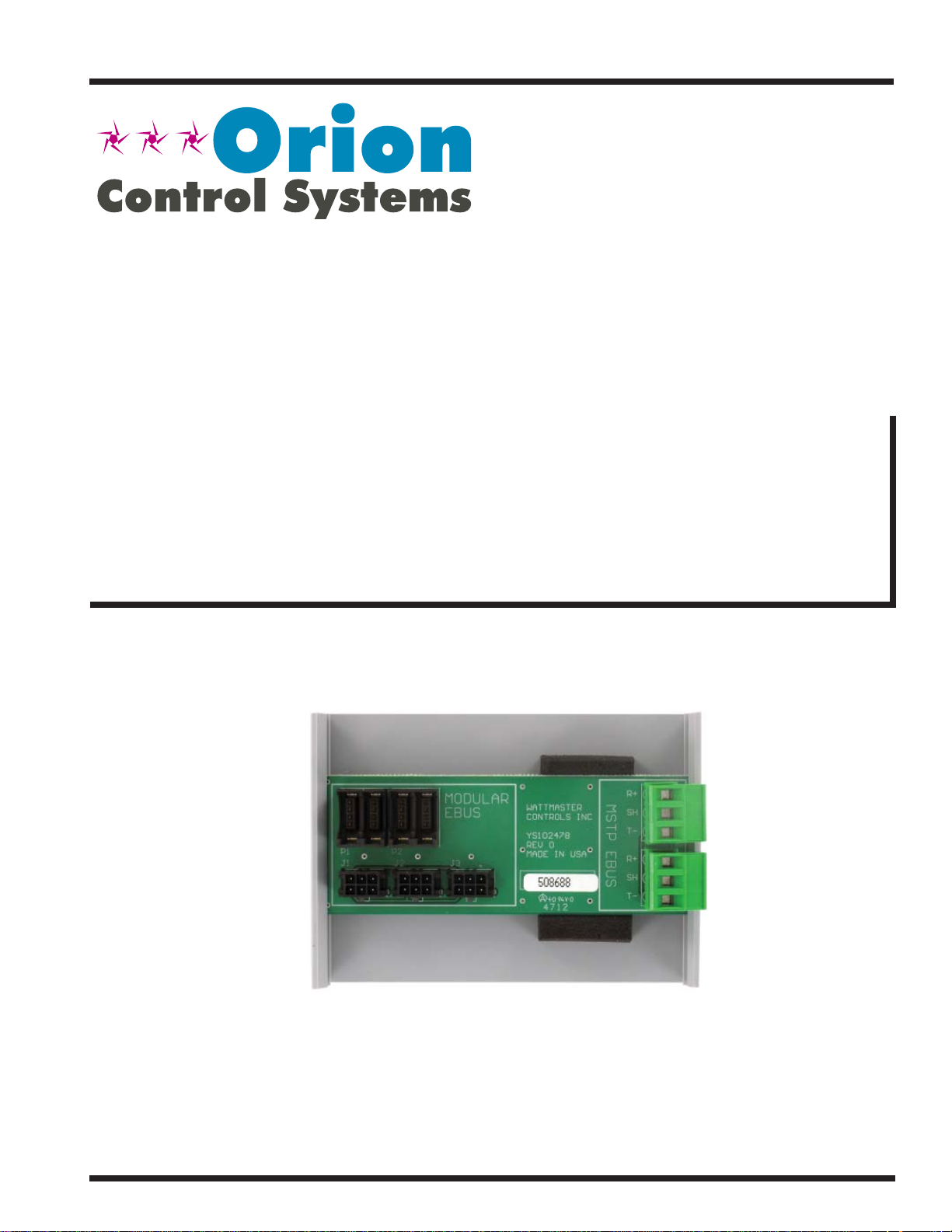
The OE365-15-EBA E-BUS Adapter Board (Figure 1) is used to
provide a connection point for multiple E-BUS Sensors or Modules
when added communication wiring length is needed.
The E-BUS Adapter Board is also used for connecting an EBTRON
GTC-116 Airfl ow Measurement Digital Transmitter, a GreenTrolTM
GA-200-N Transmitter Module with GF Series Airfl ow Monitor-
ing Station, or Paragon MicroTransEQ series Airfl ow Measurement
Digital Transmitter to the VCM-X E-BUS Modular Controller*,
RNE Controller*, or VCB-X Controller.
You must wire the EBTRON®, GreenTrolTM, or Paragon* Airfl ow
Measurement Digital Transmitter to this Adapter Board.
The E-BUS Adapter Board has (4) Modular E-BUS ports, (3) HSSC
Connections, and (2) MSTP E-BUS Connections.
®
NOTE: With custom VCM-X or RNE software, the Paragon
MicroTrans EQ series Air Flow Monitoring Station
can be used and would wire into the E-BUS Adapter
Board the same way.
®
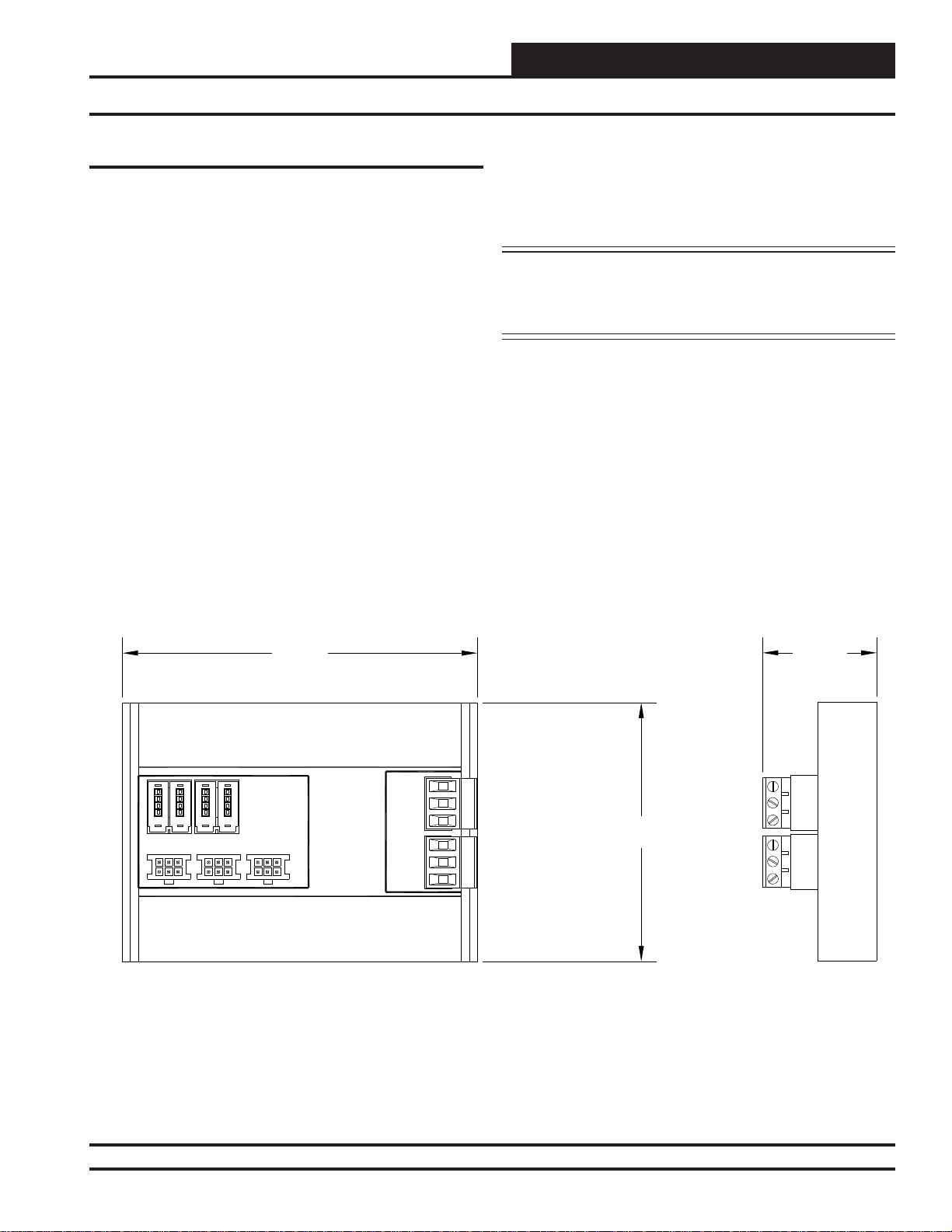
4.12
MODULAR
EBUS
P2P1
J1
J2 J3
YS102478
REV 0
MADE IN USA
R+
MSTP EBUS
SH
T-
R+
SH
T-
3.00
1.33
Figure 1: E-BUS Adapter Dimensions
Technical Guide
Revised: 10/23/13
3
Page 4

E-BUS Adapter Board
E-BUS Modules to VCM-X E-BUS or RNE Controller Wiring
Connecting Multiple E-BUS Modules
to the VCM-X E-BUS or RNE Controller
If using multiple E-BUS Modules, the E-BUS Adapter Board can
be used when the one HSSC E-BUS port on the VCM-X E-BUS or
RNE Controller is not enough.
Connect To
VCM-X E-BUS Port
Or RNE E-BUS Port
ANALOG INPU
JUMPER
SETTINGS
AI1 SET
AI1
AI2 SET AI3 SET
AI2
AI3
AI4
AI5
AI4 SET AI5 SET AI7 SET
AI7
THERM
4-20mA
AI1
0-10V
0-5V
THERM
4-20mA
AI2
0-10V
0-5V
THERM
4-20mA
AI3
0-10V
0-5V
THERM
EMERGENCY SHUTDOWN
4-20mA
AI4
0-10V
0-5V
THERM
4-20mA
AI5
0-10V
0-5V
THERM
4-20mA
AI7
0-10V
0-5V
ANALOG INPUTJUMPER SETTINGS
MUSTBE SET AS SHOWN FOR
PROPER OPERATION
STATIC
WattMaster Label
#LB102033-01
PRESSURE
Up to (2) E-BUS Modules can be connected to the E-BUS Adapter
Board’s HSSC E-BUS ports. The Unit Controller connects to the
third HSSC E-BUS port on the E-BUS Adapter Board.
See Figure 2 below for details when connecting multiple E-BUS
Modules to a VCM-X E-BUS Controller or RNE Controller.
WARNING!!
Observe Polarity! All boards
must be wired with GND-to-GND
and 24 VAC-to-24 VAC. Failure
To observe polarity could result in
damage to the boards.
OE332-23E-VCMX-MOD
VCM-X E-BUS Controller
Size Transformer For
Correct Total Load.
VCM-X E-BUS or RNE
Controller = 8 VA.
NOTE:
Power Terminal
Block Not Shown.
24 VAC POWER ONLY
WARNING!POLARITY MUST BE OBSERVED
OR THE CONTROLLER WILLBE DAMAGED
I2C
EXPANSION
I2C DIGITAL
SENSOR
HSSC Cable Connect To
HSSC E-BUS Port
OE365-15-EBA
E-BUS Adapter Board
HSSC Cables Connect To
HSSC E-BUS Ports
HSSC Cables Connect To
E-BUS Modules’ E-BUS
Ports
Figure 2: Multiple E-BUS Modules Wiring to Unit Controller Using the E-BUS Adapter (VCM-X E-BUS
Controller Shown)
4
Technical Guide
Page 5

E-BUS Adapter Board
Airfl ow Monitoring Station to VCM-X E-BUS or RNE Controller Wiring
Connecting to the VCM-X E-BUS or
RNE Controller
NOTE: Only the EBTRON® GTC116 series* or GreenTrolTM
GA-200-N Module (with GF series Airfl ow Station)
of MODBUS transmitters are compatible with the
VCM-X E-BUS or RNE Controller.** No other series of
EBTRON® or GreenTrolTM transmitters will work for
this application.
The E-BUS Adapter Board attaches to the VCM-X E-BUS or RNE
Controller with an HSSC E-BUS cable (supplied separately). The
Adapter Board is used for connecting the EBTRON® or GreenTrol
Airfl ow Measurement Digital Transmitter to the VCM-X E-BUS
or RNE Controller. You must wire the EBTRON® or GreenTrolTM
Connect To
VCM-X or RNE E-BUS Port
OE332-23E-VCMX-MOD
VCM-X E-BUS Controller
ANALOG INPU
JUMPER
SETTINGS
AI1 SET
AI1
AI2 SET AI3 SET
AI2
AI3
AI4
AI5
AI4 SET AI5 SET AI7 SET
AI7
THERM
4-20mA
AI1
0-10V
0-5V
THERM
4-20mA
AI2
0-10V
0-5V
THERM
4-20mA
AI3
0-10V
0-5V
THERM
EMERGENCY SHUTDOWN
4-20mA
AI4
0-10V
0-5V
THERM
4-20mA
AI5
0-10V
0-5V
THERM
4-20mA
AI7
0-10V
0-5V
ANALOG INPUTJUMPER SETTINGS
MUSTBE SET AS SHOWN FOR
PROPER OPERATION
STATIC
WattMaster Label
#LB102033-01
PRESSURE
EXPANSION
TM
Size Transformer For
Correct Total Load.
VCM-X E-BUS or RNE
Controller = 8 VA.
Power Terminal Block Not
Shown.
24 VAC POWER ONLY
WARNING!POLARITY MUST BE OBSERVED
OR THE CONTROLLER WILLBE DAMAGED
I2C
Airfl ow Measurement Digital Transmitter to the Adapter Board as
shown in Figure 3.
NOTE: Up to 3 EBTRON
®
or GreenTrolTM Airfl ow
Measurement Digital Transmitters can be
attached to each Adapter Board.
*NOTE: When confi guring the GTC-116 Series, be sure to
set the Parity to “NO PARITY, 1 STOP BIT.”
**NOTE: With custom VCM-X / RNE software, Paragon Micro-
TransEQ Airfl ow Stations can be used and would wire
into the E-BUS Adapter Board the same way. The
Paragon MODBUS ID must be set to 9 and the baud
rate must be set to 9600.
WARNING!!
Observe Polarity! All boards
must be wired with GND-to-GND
and 24 VAC-to-24 VAC. Failure
To observe polarity could result in
damage to the boards.
NOTE:
Airflow Measurement
Digital Transmitter Terminals
For Supply Air CFM
(Set Address Switch To 11)
Airflow Measurement
Digital Transmitter Terminals
For Return or Exhaust Air CFM
(Set Address Switch To 10)
I2C DIGITAL
SENSOR
NET+
NETCOMM
NET+
NETCOMM
Airflow Measurement
Digital Transmitter Terminals
For Outdoor Air CFM
(Set Address Switch To 9)
OE365-15-EBA
E-BUS Adapter Board
HSSC Cable Connect To
HSSC E-BUS Port
NET+
NETCOMM
NOTE: One Or Both
Terminal Blocks Can be
Used.
Figure 3: EBTRON® GTC116 Series and GreenTrolTM GA-200-N Series to VCM-X E-BUS or RNE Controller
Wiring (VCM-X E-BUS Controller Shown)
Technical Guide
5
Page 6

E-BUS Adapter Board
E-BUS Modules and/or Sensors to VCB-X Controller Wiring
Connecting Multiple E-BUS Modules
and/or Sensors to the VCB-X
Controller
If using multiple E-BUS Sensors or Modules, the E-BUS Adapter
Board can be used when there are not enough available E-BUS ports
on the Unit Controller.
WARNING!!
Observe Polarity! All boards
must be wired with GND-to-GND
and 24 VAC-to-24 VAC. Failure
To observe polarity could result in
damage to the boards.
Size Transformer For
Correct Total Load.
VCB-X Controller = 8 VA
OE265-15-A Horizontal
Temperature
& Humidity Sensor
Up to (3) E-BUS Modules or Sensors can be connected to the E-BUS
Adapter Board(s) MODBUS E-BUS ports. The VCB-X Controller connects to the fourth MODBUS E-BUS port on the E-BUS
Adapter Board.
See Figure 4 for wiring details when connecting multiple E-BUS
modules and/or sensors to the VCB-X Controller.
AO2
=
AO3
= SC
TRIAC OUTPUT
TR1
= DIGITAL CO
M
LED N
WattMaster Label
#LB102093-01-A
Rev.: 1C
24 VAC POWER
ONLY
WARNING!
POLARITY MUST
BE OBSERVED
OR THE
CONTROLLER
WILL BE
DAMAGED
24 VAC
INPUT
NORMAL
SAT FAIL
OAT FAIL
SPC FAIL
MECH COOL FAIL
MECH HEAT FAIL
FAN PROOFFAIL
DIRTY FILTER
EMERGENCY SHUTDOWN
LOW SAT 1
HIGH SAT 2
CONT. TEMP COOL FAIL 3
CONT. TEMP HEAT FAIL 4 4
PUSH BUTTON OVR 1 5
OUTPUT FORCEACTIVE 0 6
E-BUS
EXPANSION
E-BUS
EXPANSION
OE335-23-VCBX
VCB-X Controller
NOTE: Connect
the VCB-X
Controller To The
E-BUS Adapter’s
Modular E-BUS
Port.
OE365-15-EBA
OE256-07 Duct Mounted
E-BUS CO Sensor
2
EBC E-BUS Cable
with Jack
Connection
Line
Voltage
EBC E-BUS Cable with
Jack Connection
4 3 2 1
1.2
37X04
3M
<PC>
1.6
4 3 2 1
1.2
37X04
3M
<PC>
1.6
NOTE: Connect both
Sensors to the E-BUS
Adapter’s Modular
E-BUS Ports Using The
GND
24VAC
E-BUS Adapter Board
Provided EBC E-BUS
Cables.
Figure 4: Multiple E-BUS Sensors Wiring to VCB-X Controller Using the E-BUS Adapter
6
Technical Guide
Page 7

E-BUS Adapter Board
Airfl ow Monitoring Station to VCB-X Controller Wiring
Connecting to the VCB-X Controller
NOTE: Only the EBTRON
GA-200-N Module (with GF series Airfl ow Station) or
Paragon MicroTransEQ series of MODBUS transmitters are compatible with the VCB-X Controller. No
other series of EBTRON®, GreenTrolTM, or Paragon
transmitters will work for this application. Contact
WattMaster Controls for information on other
airfl ow station options.
The E-BUS Adapter Board attaches to the VCB-X Controller with
an EBC E-BUS cable (supplied separately). The Adapter Board
is used for connecting the EBTRON
Airfl ow Measurement Digital Transmitter to the VCB-X Control
System. You must wire the EBTRON®, GreenTrolTM, or Paragon
Airfl ow Measurement Digital Transmitter to the Adapter Board as
shown in Figure 5.
AO2
=
AO3
= SC
TRIAC OUTPUT
TR1
= DIGITALCO
WattMaster Label
#LB102093-01-A
Rev.: 1C
24 VAC POWER
ONLY
WARNING!
POLARITY MUST
BE OBSERVED
OR THE
CONTROLLER
WILL BE
DAMAGED
24 VAC
INPUT
Line
Voltage
Size Transformer For
Correct Total Load.
VCB-X Controller = 8 VA
GND
24VAC
®
GTC116 series. GreenTrolTM
®
or GreenTrolTM, or Paragon
OE335-23E-VCBX
VCB-X Controller
M
LED N
NORMAL
SATFAIL
OATF AIL
SPC FAIL
MECH COOL FAIL
MECH HEAT FAIL
FANPROOF FAIL
DIRTY FILTER
EMERGENCY SHUTDOWN
LOW SAT 1
HIGH SAT 2
CONT. TEMP COOL FAIL 3
CONT. TEMP HEAT FAIL 4 4
PUSH BUTTON OVR 1 5
OUTPUTFORCE ACTIVE 0 6
E-BUS
EXPANSION
E-BUS Cable
(EBC Cable)
E-BUS
EXPANSION
NOTE: Up to 4 EBTRON
®
, GreenTrolTM, or Paragon
Airfl ow Measurement Digital Transmitters can be
attached to each Adapter Board.
NOTE: If using multiple E-BUS Sensors or Modules, the
E-BUS Hub (HZ-EBC-248 or MS000248) may be
required.
*NOTE: When confi guring the GTC-116 Series, be sure to set
the Parity to “NO PARITY, 1 STOP BIT.”
Airflow Measurement
Digital Transmitter Terminals
NET+
NETCOMM
NET+
NETCOMM
NET+
NETCOMM
NET+
NETCOMM
For Exhaust Air CFM
(Set Address Switch To 12)
Airflow Measurement
Digital Transmitter Terminals
For Supply Air CFM
(Set Address Switch To 11)
Airflow Measurement
Digital Transmitter Terminals
For Return Air CFM
(Set Address Switch To 10)
Airflow Measurement
Digital Transmitter Terminals
For Outdoor Air CFM
(Set Address Switch To 9)
WARNING!!
Observe Polarity! All boards
must be wired with GND-to-GND
and 24 VAC-to-24 VAC. Failure
To observe polarity could result in
damage to the boards.
OE365-15-EBA
E-BUS Adapter Board
NOTE: One Or Both
Terminal Blocks Can be
Used.
Figure 5: EBTRON® GTC116 Series, GreenTrolTM GA-200-N Series, and Paragon MicroTransEQ Series Wiring
Technical Guide
Revised: 10/23/13
7
Page 8

Form: OR-EBUS-ADAPTER-TGD-01B Printed in the USA October 2013
All rights reserved. Copyright 2013
WattMaster Controls Inc. 8500 NW River Park Drive Parkville, MO 64152
Phone: 866-918-1100 www.orioncontrols.com Fax (816) 505-1101
 Loading...