

Page 1
0
Description
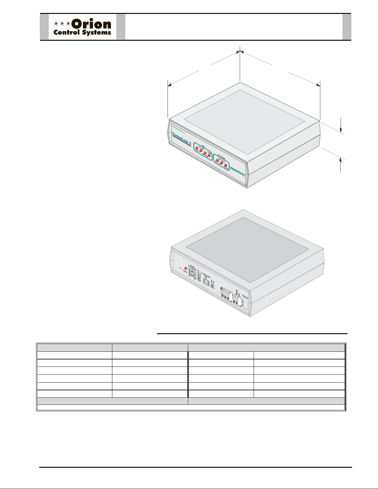
The OE361-13 CommLink 5 Communications
Interface allows computer access into the
Orion controls system and also provides
communications across multiple local communications loops on the control system.
The CommLink 5 comes packaged in an attractive beige colored plastic enclosure. The
CommLink 5 is powered by a small plug-in
transformer that is included. Locally, an optional on-site personal computer with Prism II
software installed may be connected to the
CommLink 5 to provide direct access to system control parameters. A USB cable (6 ft.
long) is provided with the CommLink 5 for
connection to your computer.
An optional OE415-02 IP Module Kit, when
installed and configured in the CommLink 5
communication interface, provides TCP IP
Internet and/or intranet connection for Ethernet networked computer systems, allowing
them to communicate with your control system. The OE415-02 IP Module Kit consists of
the IP Module and a 10 ft. long CAT5 Ethernet crossover cable.
Using standard TCP/IP Protocol, with WattMaster’s Prism II software, you are able to
monitor and configure your controllers without
a modem or a direct connection from a PC.
Utilizing existing routers, proxies, or firewalls
allows a PC running Prism II to connect to a
controller in a remote accessible location or
building. Several IP connection profiles can
be created to facilitate monitoring several
CommLink 5’s with IP Module Kits installed
on individual sites.
OE361-13 CommLink 5
Communication Interface
5.25
FRONT VIEW
)
+
D
(
L
R
)
H
-
(
S
T
7.00
1.5
Mounting
If an on-site computer is to be used for direct
connection and monitoring of the system, the
CommLink 5 should be located near the
computer terminal to monitor the system.
Technical Data OE361-13 CommLink 5 Communication Interface
Power 24 Volt AC *Ethernet Conn. RJ-45 Ethernet Port
Plug-in Transformer 120V to 24VAC (Included) Local Loop RS-485 – 9600 Baud
Power Consumption 14 VA Maximum Network Loop RS-485 –19,200 or 57,600 Baud
Operating Temperature
10F to 140F
Operating Humidity 90% RH Non-Condensing Cabling Included (1) 6 Ft. Long USB Cable
Computer Conn. USB Version 1.1 or 2.0
Three Year Warranty
* This Port Is Only Used With The Optional OE415-02 IP Module Kit.
Form: ORION-OE361-13-CMLK5-01A Page 1 of 1
Protocol HSI Open Protocol Token Passing
WattMaster reserves the right to change specifications without notice
REAR VIEW
Page 2
k
2
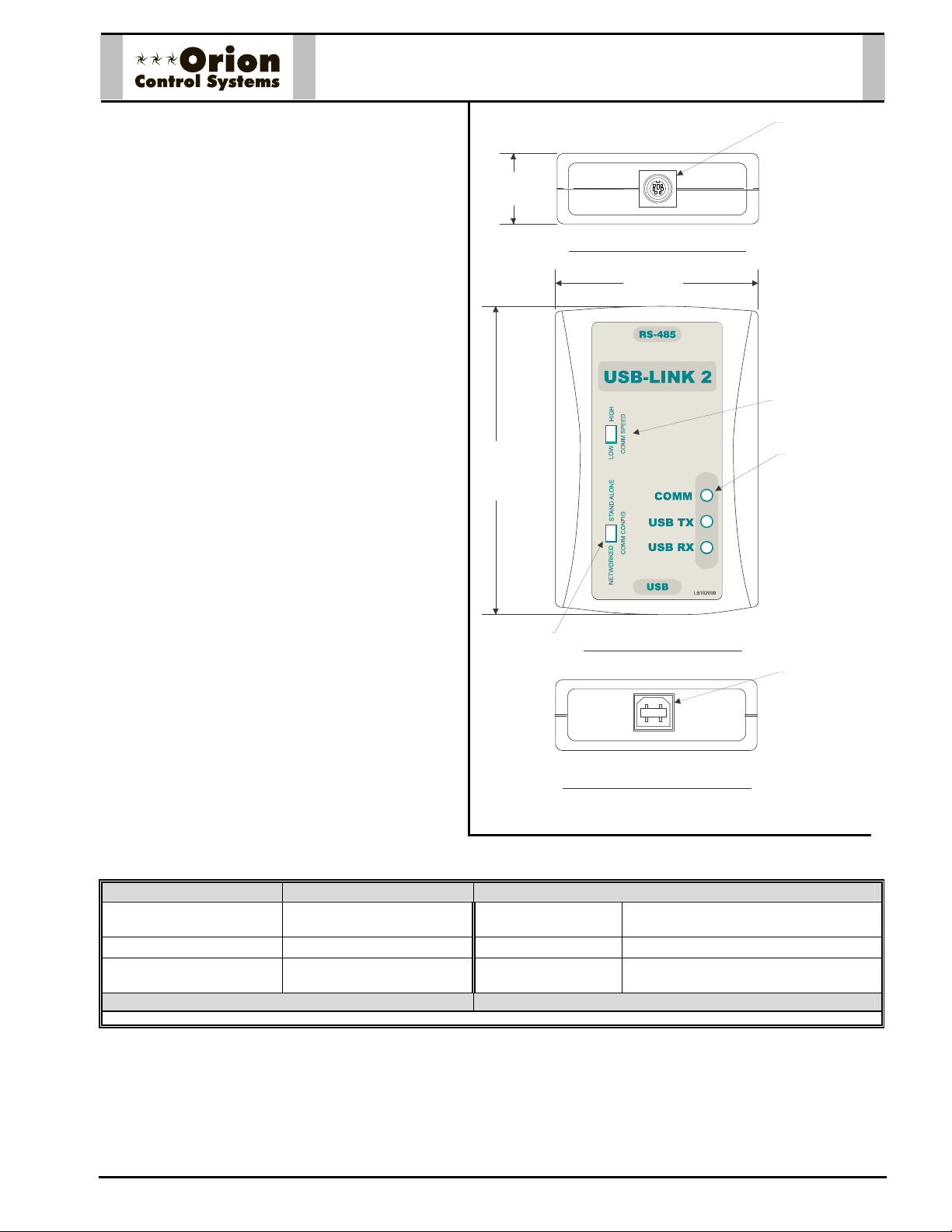
OE366 USB-Lin
Description
The OE366 USB-Link 2 allows computer access
into the Orion controls system and also provides
communications across multiple local communications loops on the control system when a
CommLink Communications Interface is installed
on the system.
The USB-Link 2 provides a direct link to enable the
system operator to view the status and to configure
and adjust the setpoints of any controller on the
control system communications loop using the
Prism II computer front end software.
The USB-Link 2 is small in size and is powered by
the USB port of the computer it is plugged into,
making it completely portable and allowing connection to the system from any controller.
The USB-Link 2 is supplied with a USB cable, a
mini- DIN male communication cable, and two
mini-DIN to terminal adapters. The communication
cable allows the user to walk up to any controller
that has a communication socket and plug in the
USB-Link to gain access to the system. The
adapters are used for boards that do not have a
female mini-DIN plug connection.
To use the USB-Link 2, you will need a computer
with an available USB 1.1 or 2.0 port with the included USB drivers installed. You will also need
the Prism II computer front end software installed
on the computer.
1.06”
3.63”
Configuration
Switch
Top End View of USB-Link 2
2.31”
STAND ALONE
NETWORK
Front View of USB-Link 2
Female 6 Pin
Mini-DIN
Connector
Communication
Speed Switch
LED - Typical
Female Type B
USB Connector
CAUTION: The USB-Link 2 does not work with
Bottom End View of USB-Link
Prism I software. It only works with Prism II.
Technical Data OE366 USB-Link 2
Operating Temperature
Operating Humidity 90% RH Non-Condensing Communications
Computer Connection USB Version 1.1 or 2.0 Adapters Included PL1019054 and PL101905 Mini-DIN
Three Year Warranty
Form: ORION-OE366-USB-Link-2-01A.doc Page 1 of 1
10F to 140F
Cabling Included (1) 6 Ft. Long USB Cable and
(1) 7 Ft. Long Communications Cable
RS-485 – 9600 to 115,000 Baud
WattMaster reserves the right to change specifications without notice
Plug Adapters
Page 3
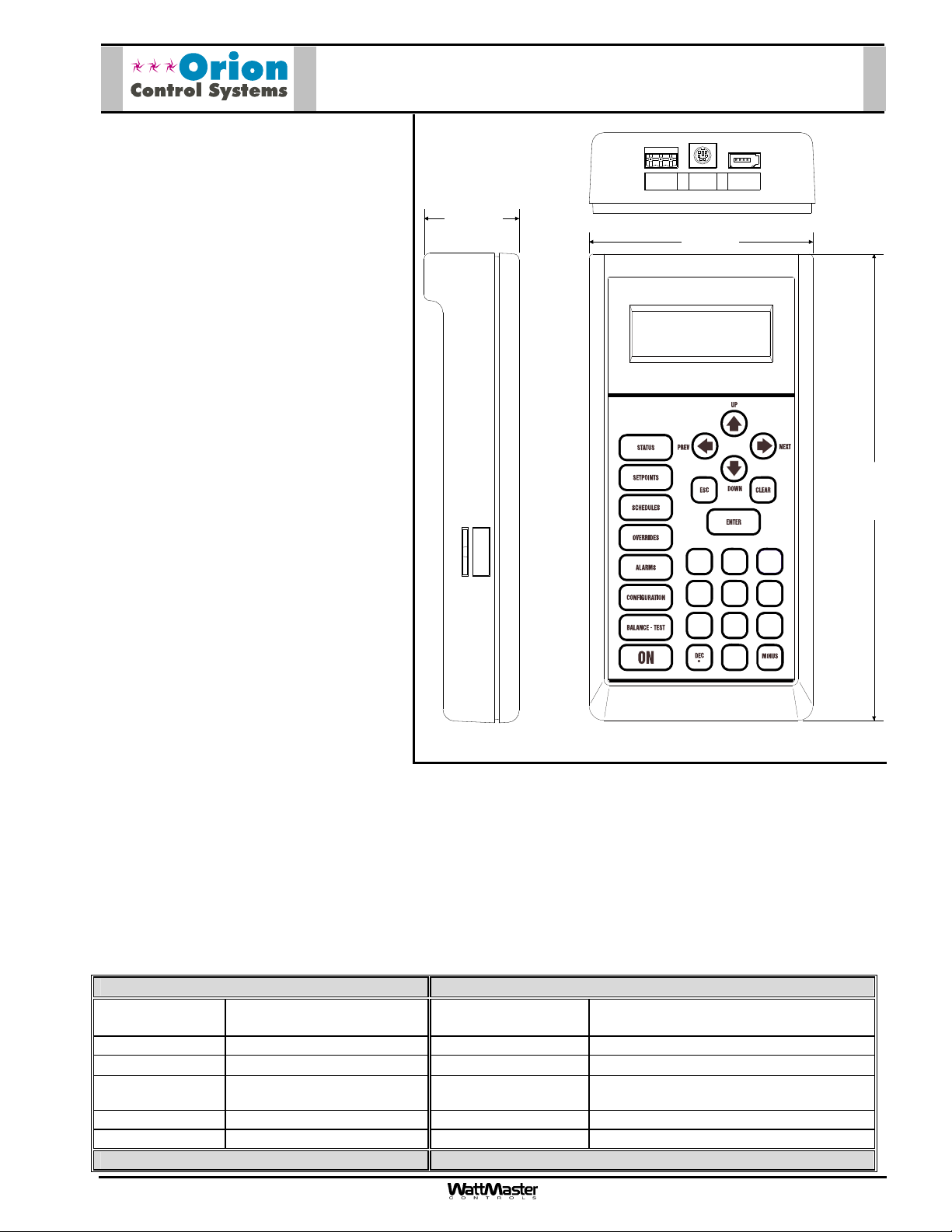
OE391-12
Modular Service Tool SD
Description
The OE391-12 Modular Service Tool SD is
a system interface that provides a direct
link to enable the system operator to view
the status, configure, and adjust the
setpoints of the following Orion controllers:
2.02"
RS-485COMM
T
HAND
R
HELD PLUG
SHLD
E-BUS
4.75”
VCM-X Series Controller
VCM-X E-BUS Series Controller
RNE Controller
VCB-X Controller
SA E-BUS Controller
VCM Controller
VAV/CAV Controller
MUA II Controller
VAV/Zone Controller
Mode
Selection
MiniLink PD
The OE391-12 Modular Service Tool SD is
housed in a black plastic enclosure. The
display area is covered with a clear plastic
bezel for protection of the display screen.
SD CARD SLOT
(Push to Eject)
The Modular Service Tool SD has a four
line by 20 character display panel with
13
2
adjustable contrast control and a 27 key
5
membrane keypad for data selection and
entry. All keypad operations are simple
and straight forward, utilizing non-cryptic
4
708
6
9
plain English language messages. Menudriven programming allows for easy setup
-
and operation without the need for
specialized training. The OE391-12
Modular Service Tool SD is supplied with a
programmable 4 Gigabyte SD memory
card, with (4) AA 1.5 V batteries, a wall
mount a DC power supply, a mini-Din communication cable, and an E-BUS communication cable. The mini-Din
cable allows you to connect the Modular Service Tool to any Orion controller which has a mini-Din connector
socket for programming, monitoring, and troubleshooting purposes.
The Modular Service Tool is also equipped with an EBC E-BUS port and an RS-485 three conductor terminal
block port. The E-BUS port and included E-BUS cable are used for updating E-BUS Module software.
The RS-485 port is used for hard-wiring to older controllers that do not have a mini-DIN connector socket.
The Modular Service Tool SD is designed to be carried by the system installer or service technician. Its rugged
plastic housing provides superior protection for the electronic components housed inside. The Modular Service
Tool SD is a top quality service tool that will stand up to the demands of the typical job site for many years.
10.00”
Technical Data OE391-12 Modular Service Tool SD
Power (4) AA (1.5V) Batteries
Supplied
Power Switch Membrane Switch Network Connection RS-485
Operating Temp
Operating
Humidity
Keypad 27 Key Membrane Style Communications RS-485 9600 or 57,600 Baud
SD Memory Card Programmable 4 Gigabyte Connections RS-485 and EBC E-BUS Ports
3 Year Warranty WattMaster reserves the right to change specifications without notice
Form: ORION-OE391-12-ModularServiceToolSD-1B.doc Page 1 of 1
90% RH Non-Condensing Color Black
10F to 149F
Display 4 Line by 20 Character
Protocol HSI Open Protocol Token Passing
Page 4

OE392-12
Description
The Modular System Manager SD (Orion
Modular System Manager SD
Part No. OE392-12) is a system interface
that provides a direct link to enable the
9.00"
system operator to view the status,
configure, and adjust the setpoints of the
following controllers:
VCM-X Series Controller
VCM-X E-BUS Series Controller
RNE Controller
VCB-X Controller
SA E-BUS Controller
VCM Controller
VAV/CAV Controller
MUA II Controller
VAV/Zone Controller
MiniLink PD
13
2
5
MINUS
-
6
9
4
708
DEC
System Manager
UP
PREV
DOWN
ENTER
CLEAR
ESC
STATUS
SETPOINTS
NEXT
SCHEDULES
OVERRIDES
ALARMS
6.25"
The OE392-12 Modular System Manager
SD is housed in a beige-colored plastic
enclosure. The Modular System Manager
SD has a programmable 4 Gigabyte SD
card and is equipped with a four line by 20
1.81"
character backlighted display panel and a
24 key membrane keypad for data
selection and entry. All keypad operations
are simple and straight forward, utilizing
non-cryptic plain English language
messages. Menu-driven programming
allows for easy setup and operation
without the need for specialized training.
The Modular System Manager SD also has 2 integral LEDs for user- notification of system alarm conditions and
override initiations. Protection from unauthorized users is provided by the System Manager’s integral multi-level
passcode authorization programming.
The Modular System Manager SD is connected to the communications and power loop of the system via modular
cables that simply plug into the System Manager board. This virtually eliminates wiring errors and makes
installation fast and easy. Alternatively, the Modular System Manager SD includes terminal blocks for power and
communications.
Mounting
The Modular System Manager is designed for wall mounting. Mounting holes are provided to attach the Modular
System Manager to a standard handy box. It is recommended that the System Manager be mounted at
approximately eye level to allow for ease of programming and reading of the display. The System Manager is
typically mounted in the building manager or superintendent’s office or in an equipment room. The attractive
enclosure is quite suitable for mounting in any location or with most decors.
Technical Data OE392-12
Modular System Manager SD
Power 24 Volt AC/DC Display 4 Line by 20 Character Backlighted LCD
Power Consumption 5 VA Maximum Network Connection RS-485
Operating Temp
Operating Humidity 90% RH Non-Condensing Housing Material Beige Plastic
Keypad 24 Key Membrane Style Communications RS-485 - 9600 or 57,600 Baud
SD Memory Card Programmable 4 Gigabyte
3 Year Warranty WattMaster reserves the right to change specifications without notice
Form: ORION
-OE392-12-ModularSystemManager-1A.doc Page 1 of 1
10F to 149F
Protocol HSI Open Protocol Token Passing
Page 5

Description
The OE392-10 System Manager TS II
provides a direct graphic-enhanced,
menu- driven link to enable the system
operator to view the status and to adjust
the setpoints of any controller on the Orion control system.
The System Manager TS II is equipped
with a 4.3” 480 x 272 WQVGA RGB TFT
LCD Touch Screen Display able to
display 16 million colors. The System
Manager TS II utilizes a graphical touch
screen menu system with easy to understand menu trees and icons and noncryptic plain English language messages.
The graphic programming and status
screens are very intuitive and provide the
user with easy setup and operation without the need for specialized training. Protection from unauthorized users is provided by the System Manager TS II’s integral multi-level passcode authorization
programming.
The System Manager TS II is connected
to the local communications loop of the
Orion system via 18 AWG 2-conductor,
twisted pair wire with shield wire connected to the T, SHLD & R communications terminals on the back of the System
Manager TS II. The communications wire
used can be either our WattMaster #WR-LL-WG-18 communications wire or Belden #82760 wire or its equivalent. The System Manager TS II also requires that 24 VAC (6 VA) power be supplied (by others) to its + and –
wiring terminal located on the back of the System Manager TS II.
System Manager TS II
OE392-10
Mounting
The System Manager TS II is housed in a plastic enclosure designed for mounting in hollow drywall construction
with the flush mount version (shown) or on a concrete, brick or other solid wall surface with the surface mount
version (optional). The flush mount version has integral wing nut paddles that are tightened after installation to
grip the drywall and hold the System Manager TS II in place. The surface mount version is designed to be installed to a double duplex outlet box (by others). Both mounting styles of the System Manager TS II feature an
integral magnetically-secured face plate which can be easily removed for reset of the display when required. The
System Manager TS II should be mounted at approximately eye level to allow for ease of programming and reading of the display. The System Manager TS II is typically mounted in the building manager’s or superintendent’s
office or in an equipment room, but is also quite suitable for mounting in any location or with most decors.
Technical Data OE392-10 System Manager TS II
Display 4.3” 480x272 WQVGA RGB
TFT LCD Touch Screen
Display w/ 16 million colors
Power Supply 24 VAC Single 60 Hz Protocol HSI Open Protocol Token Passing
Power Consumption 5 VA Maximum Housing Material Plastic
Operating Temp
Operating Humidity Less than 90% RH
3 Year Warranty WattMaster reserves the right to change specifications without notice
Form: ORION-OE392-10-SysMgr-TS-II-FM-1B.doc Page 1 of 1
14F to 158F
Non-Condensing
Communication
Connection
Communications Isolated RS-485
User
Interface Method
LCD Touch Screen
RS-485
Page 6

Description
The OE-364-22 MiniLink Polling Device is
a network controller that is used to integrate multiple local communication loops
into a network communications system.
Network loop terminals of the MiniLink
Polling Device are designed to be connected to the CommLink and to other
MiniLink Polling Devices on the network
communications loop. Local loop terminals of the MiniLink Polling Device are
designed to be connected to controllers
installed on the local communications
loop. The MiniLink Polling Device can be
connected to the communication loops
and power loop of the system controllers
via modular cables that simply plug into
the MiniLink Polling Device board. This
virtually eliminates wiring errors and
makes installation fast and easy.
The MiniLink Polling Device utilizes token
passing communication architecture. The
MiniLink Polling Device is designed to
serve as the local communications loop
master. This means that it is responsible
for sending the token to all the controllers
on the local communications loop. Network communications are of the RS-485
type operating at 19,200 baud. Local
communications are also of the RS-485
type and operate at 9600 baud. The
MiniLink PD is required for zoning systems to facilitate voting of the zones to
determine the HVAC units heating and
cooling mode of operation. It also provides tenant-logging capabilities.
OE364-22 – MiniLink
Polling Device
MiniLink Polling Device Is Supplied Factory Mounted To
Control Enclosure. Cover Shown Removed For Clarity
Mounting
The MiniLink Polling Device is factory
mounted in a galvanized sheet metal enclosure. Mounting holes are provided in
the enclosure for surface mounting.
Technical Data OE364-22 – MiniLink
Polling Device
Power 24 Volt AC System Connection Molex® Connectors & Terminals
Power Consumption 6VA Maximum Network Connection RS-485
Operating Temp
Operating Humidity 90% RH Non-Condensing Housing Material 22 Ga. Galvanized Steel
Communications RS-485 - 9600 Baud, Local Communications RS-485 - 19200 Baud, Network
3 Year Warranty WattMaster reserves the right to change specifications without notice
Form: ORION-MiniLinkPollingDevice-1C.doc Page 1 of 1
10F to 149F
Protocol HSI Open Protocol Token Passing
Page 7

OE415-02 IP Module Kit
Description
The OE415-02 IP Module Kit (when installed and
configured in the CommLink IV or CommLink 5
communication interface) provides TCP/IP Internet
and/or intranet connection for Ethernet networked
computer systems allowing them to communicate
with your control system. The OE415-02 IP Module
Kit consists of the IP Module and a 10 ft. long
CAT5 Ethernet crossover cable.
The IP Module plugs into a mating 40 pin (2 x 20)
connector located on the CommLink’s circuit
board. Installation is easily accomplished by removing the CommLink’s case cover screws, removing the case cover to access the circuit board,
and then plugging the IP Module into its mating
socket connector. Correct alignment is made easy
because of the (4) slot alignment tabs located
around the perimeter of the processor base. It is
not possible to incorrectly align the IP Module to
the socket connector because of this feature.
The TCP/IP connection provided by the IP Module
installed in the CommLink is a TCP connection on
a single port number and is static in nature. Firewall and proxy servers can easily be configured to
allow traffic to and from the CommLink when the IP
Module is installed. The nature of the data is raw in
form and comprised of packets native to Prism II
software. The IP Module will respond to ICMP traffic (PING) for verification of proper configuration.
Prism II software is required in order to read and
send data to the IP Module and through the
CommLink to the control system. The IP Module
connects to the host Ethernet system by means of
the supplied 10 ft. long CAT 5 Ethernet crossover
cable which plugs into the 10/100 Base-T, RJ-45
jack on the back of the CommLink IV and into a Ethernet router or Ethernet modem on your building’s LAN. Setup of the CommLink with the IP Module requires a knowledgeable IT person familiar with configuring network
adapters and TCP/IP systems. Prism II software must be installed on the local LAN computer(s) and/or remote
Internet computers that will be used to program and monitor the control system.
1.34”
CAT5 Ethernet Cable
1.28”
IP Module
Technical Data
Operating Temperature
Operating Humidity 90% RH Non-Condensing Network Connection 10/100 Base-T Ethernet
Protocols Supported ARP, UDP, TCP, Telnet,
Network Interface IEEE 802.3 RJ45 Ethernet
3 Year Warranty
Form: Orion-OE415-02-IPModuleKit-01B.doc Page 1 of 1
OE415-02 IP Module Kit
10F to 140F
ICMP, SNMP, DHCP, BOOTP,
Auto IP, HTTP, SMTP, TFTP
10BASE-T Or 100BASE-TX
(Auto-sensing)
Media Access Control CSMA/CD with ACK
RJ-45 MDI Socket
Flow Control XON/XOFF (Software), CTS/RTS
(Hardware), None
Management Internal Web Server, SNMP (Read
Only), Serial Login, Telnet Login,
Device Installer Software
WattMaster reserves the right to change specifications without notice
Page 8

Description
Prism II is a complete Windows® based
graphical interface that allows you to interact
with your Orion digital controls systems. The
program provides standard, easy-tounderstand status, setpoint, and configuration
screens for each type of controller and has
provisions for custom screens which allow
floor plans, equipment photos, or user defined
summary screens.
Prism II allows you to access and control
schedules, trend logs, and alarm conditions.
The program can be configured for direct onsite installation, remote modem connection,
or TCP/IP Internet connection.
The Prism II program is a completely redesigned release of the original Prism Graphical
Computer Interface. This program should be
used on all new installations containing
standard Orion Control product families.
Feature Summary
OE508 Prism II Graphical
Computer Front End Software
Prism II provides a broad set of features:
Easy to use
•
On-site, remote modem, or TCP/IP communications
•
User programmable description for every piece of equipment and user-defined custom screens
•
Automatic retrieval of trend logs and export capability to spreadsheet and database programs
•
Alarm Logs maintained on disk
•
Alarm E-mail capability
•
Encrypted History Logs
•
System Requirements
To use Prism II you must have a computer that meets or exceeds the following requirements:
Operating System
®
Microsoft
•
Windows® 2000/ Windows® Vista, or Windows® 7
Minimum Hardware
®
Windows
•
Pentium 2 GHz Processor (Pentium 4 2 GHz or greater,
•
1 GB RAM or greater)
•
120 MB hard drive space
•
XVGA (1024 x 768) adapter and monitor
•
(1280 x 1024,
Network card for TCP/IP connection when IP Module is used.
•
compatible computer
Recommended
)
Recommended
)
System Requirements
Prism II is available on a CD or can be downloaded for free from the Orion Controls web site at
www.orioncontrols.com. Prism II does not require any license agreement and may be freely copied and distribut-
ed.
Form: Orion-OE508-PismII-1A-Sub.doc Page 1 of 1
Page 9

PCC - Power & Comm Cable
Description
The PCC & PCCE Power &
Comm Cables are used to
connect power and comm unications wiring from the Power
& Communications Distribution Board to VAV/Zone Controllers and other Orion System peripheral devices. They
are also used to connect between VAV/Zone Controllers
on each loop of the system.
The Power & Comm Cables
consist of 5 conductor
(16AWG) with shield wire,
plenum rated cable and are
terminated at both ends with
Molex® plug-in connectors.
The PCC Power & Comm Cables are available in 25, 40, 80
and 120 feet lengths. These
lengths should satisfy most
job requirements. For length
requirements outside of thes e
ranges the PCCE Power &
Comm Extension Cables are
available in 10 and 20 feet
lengths to eliminate any need
for splicing cables. The Molex® connector plug-in design
of the cables eliminates c ostly
wiring errors and makes system installation easy. The cable components are UL approved.
PCCE – Power & Comm Extension
Cable End View
Cable End View
Male Molex End Connector
®
Shrink Wrap Tubing
Plenum Rated Cable
(5 Conductor w/ Sheild)
Cable Length
Shrink Wrap Tubing
PCC Power & Comm Cable Assembly
Available in 25, 40, 80 or 120 Feet Lengths
Female End ConnectorMolex
Shrink Wrap Tubing
®
Plenum Rated Cable
(5 Conductor w/ Sheild)
Cable Length
Shrink Wrap Tubing
PCCE Power & Comm Extension Cable
Available in 10 or 20 Feet Lengths
Male End ConnectorMolex
Male End ConnectorMolex
Cable
®
Cable End View
®
Cable End View
Technical Data PCC & PCCE – Power & Comm Cables
Model PCC Cable
Available Lengths and
Part Numbers
PCC-25 (25 Ft.)
PCC-40 (40 Ft.)
PCC-80 (80 Ft.)
Model PCCE Cable
Available Lengths and
Part Numbers
PCC-120 (120 Ft.)
Cable Type Plenum Rated CMP/CL2P Current Rating of Connectors 8 Amps
Wire Size 16 Gauge Stranded
UL Listing Number UL E118871
5 Conductor With Shield
Model PCC Terminations
Model PCCE Terminations
(2) Molex® Mini-Fit Jr.
Plug Connectors
(1) Molex® Mini-Fit Jr. Receptacle
Connector and (1) Molex®
Cable Color Off White
Wire Colors White, Red, Black,
Mini-Fit Jr. Plug Connector
Three Year Warranty
Form: ORION-PowerCable-PCC-PCCE-1B.doc Page 1 of 1
WattMaster reserves the right to change specifications without no-
PCC-10 (10 Ft.)
PCC-20 (20 Ft.)
Clear, Green
tice
Page 10

OE365-01 – Power & Communication
Distribution Board
Description
The OE365-01 – Power & Communications Distribution Board is used as a distribution point for power and com munications wiring for VAV/Zone Controllers and
other Orion System peripheral devices.
The Power & Communications Distribution board is designed to allow for the
connection of up to a maximum of 6
VAV/Zone controllers per branch output
connector. The 4 branch outputs are each
provided with Molex connector female
sockets on the board. Terminal Blocks
are provided for connection of Power &
communications wiring to the board. The
board provides for total power distribution
of up to 80VA at 24VDC. This allows up
to 20 VAV/Zone Controllers to be connected to the board. The 24VDC power
circuit is fused on the board to protect the
branch circuits. The RS-485 communications wiring is also routed through the
Molex modular connectors, providing
communications to all controllers on the
loop served by the Power & Communications Distribution Board.
TB1
COMMP IN
P2
TB2
C1
T
SHLD
R
POWER
LD1
24
VAC
25
F1
Snap Track
3.50”
POWER & COMM
DIST. BOARD
YS101856
REV. 0
R1
V1
4A
P5
P4
POWER & COMM
OUT
P3
D1
P1
Power & Communications
Distribution Board
4.19"
Connection to the VAV/Zone controller
boards and other devices on the branches is achieved by utilizing 5 conductor w/ drain wire, plenum rated prefabricated modular cables available f rom WattMaster. T he m ain cables are term inated on each end with m ale Molex
connectors. This allows for plug in connection to all boards on the branch circuits thereby virtually eliminating
costly wiring errors. The modular c ables are available in various lengths to suit almost any wiring requirem ent.
Male to female extension cables are available to eliminate any need for splicing cables.
Mounting
The OE365-01 Power & Communications Distribution Board is supplied mounted on a plastic Snap Track channel. The Snap Track channel has two mounting holes, which are used to field mount the board with the provided
screws.
Technical Data OE365-01 – Power & Communication
Distribution Board
Input Power
Output Power
Operating Temp
Power and Communications
connections
Qty of Branch Circuits Provided For VAV/Zone Controller and Other Peripheral
Boards
Three Year Warranty
24 VAC @ 100VA
Power Fusing 4 Amp Slow Blow Fuse
24 VDC @ 80VA
10°F to 149°F
Operating Humidity 90% RH Non-Condensing
Molex Connectors Weight 8 oz
Mounting Provisions Supplied with
4
Snap Track Base
WattMaster reserves the right to change specifications without notice
Form: ORION-OE353-4SlotBaseBoard-1B.doc Page 1 of 1
 Loading...