

Page 1
A
A
A
A
A
A
A
A
Description
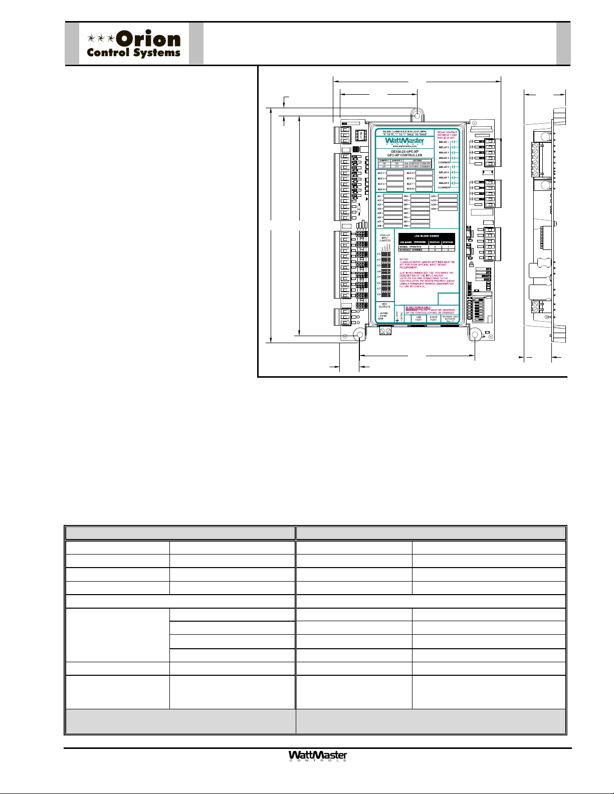
The OE338-23-GPCXP GPC-XP Controller is
used for controlling equipment or processes
0.290.29
that cannot be controlled using a standard
HVAC controller.
The GPC-XP provides the flexibility to control, schedule and/or monitor equipment such
as unit heaters, exhaust fans, motorized
dampers, pumps, and other mechanical
equipment. It can also be used for simple
boiler, chiller, or refrigeration applications as
well as to provide lead/lag start function.
The GPC-XP has an on-board CommLink
that provides for stand-alone programming
and monitoring via a direct USB connection
to a computer running Prism II software. If
used on a networked system that has an external CommLink, this on-board CommLink
would not be used.
The GPC-XP has (8) configurable analog
inputs which will accept signals from thermistor temperature sensors or from 4-20mA, 0-
8.388.38
7.837.83
BINARY
INPUTS
ANALOG
INPUTS
VDC
OUTPUTS
LOOP COMM
TB1
TB3
TB7
TB8
T-
SH
R+
ON BOA
COMMLI
CONNEC
R38
BIN1
300
D6
R41
BIN2
300
D7
R43
300
BIN3
R47
D8
300
BIN4
D9
BIN5
300
D10
300
BIN6
D11
300
BIN7
R61R59R55R51
D12
300
BIN8
D13
COM
CUTTO ISOL
COMFROM GND
COM
COM
TE
COM
4-20mA
THERM
0-10v
0-5v
AI1
AI1
AI2
AI3
AI2
AI4
AI5
AI3
AI6
AI7
AI4
AI8
GND
AI5
GND
AI6
GND
GND
I7
AI8
+24V
+5V
GND
5VDC, or 0-10VDC transmitters. The inputs
are set for the desired scaling by means of a
jumper bar. Custom formulas created by
available math functions and operators can
0.700.70
be used in conjunction with the analog inputs
to create a calculated value to be used and displayed for a specific analog input. An additional modular input is available for
WattMaster communicating sensors. The GPC-XP has (8) wet contact binary inputs that can be configured for either normally
open or normally closed operation. Also available are (8) relay outputs for on/off control and (4) analog outputs (0-10VDC) for
modulating control. Highest/lowest/average of the analog input values can be used in the GPC-XP logic or broadcast to other
controllers on the control system loop. There are (8) separate two events per day schedules which can be assigned to any
input or output for operational control or for alarm recognition based on time of day. These schedules can also be configured
to broadcast to other WattMaster
controllers on the control system loop.
OE338-23-GPC-XP
GPC-XP Controller
5.985.98
2.752.75
YS102432 REV 3
WATTMASTER CONTROLS
MADE IN USA
RLY1
RLY2
RLY3
RLY4
COMMON
TB2
RELAY
OUTPUTS
TB4
RLY1
RLY2
RLY3
RLY4
COMMON
SERIAL #
ANALOG
OUTPUTS
1002
R74
U17
OUT1
AOUT1-2
OUT2
.1uF
OUT3
C36
1002
R97
OUT4
U19
OUT3-4
GND
GND
.1uF
C46
TB6
GND
STATUS1
STATUS2
EBUS
POWER
1002
R21
1002
R109
1002
R16
1002
R14
.1uF
C21
ADDRESS
ADD
1002
1
1002
2
1002
4
1002
8
1002
16
1002
32
1002
LOOP
B
1
1002
UD
2
SW1
C14
.01uF
4.104.10
1.49
0.980.98
Mounting
The GPC-XP is provided with an integral plastic enclosure which provides mounting points for mounting inside of a
control enclosure. It is recommended that the GPC-XP be mounted in a control enclosure in the building equipment
room. An optional factory control enclosure for the GPC-XP is also available.
Technical Data OE338-23-GPCXP GPC-XP Controller
Power 24 Volt AC Weight 1 lb.
Power Consumption 8 VA Maximum Network Connection RS-485 – 9600 or 57,600 Baud
Operating Temp
-30F to 150F
Protocol HSI Open Protocol Token Passing
Operating Humidity 90% RH Non-Condensing Communications E-BUS
Inputs: Outputs:
Types of Allowed
Inputs
Type III-10K Ohm Sensors Total Relay Qty. On Board 8
4-20mA Relay Power Rating (2 Amp @ 24 VAC)
0-5VDC & 0-10VDC Analog Output Qty. 4
N.O. or N.C. Contact Analog Output Signal 0-10 VDC
Total Inputs Available 16 Configurable Lead Lag Scheduling (1) Output can be Configured
Additional
1 (Modular)
Schedules Available (8) 2 Events per day
Communicating
Sensor Input
Three Year Warranty WattMaster reserves the right to
change specifications without notice
Form: ORION-OE338-23-GPCXP-Controller-01B.doc Page 1 of 1
Page 2
Description
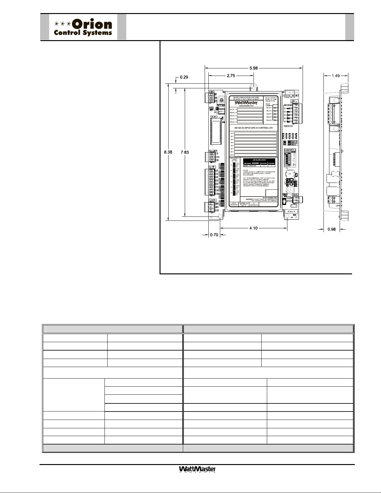
The OE332-23-GPCX GPC-X Controller
is used for controlling equipment or
processes that cannot be controlled using a standard HVAC controller. The
Prism computer front end software is
used to interface with the GPC-X controller functions. The GPC-X Controller provides the flexibility to control, schedule
and/or monitor equipment such as unit
heaters, exhaust fans, motorized louvers, and other mechanical equipment.
The GPC-X has (6) configurable inputs
which will accept signals from thermistor
temperature sensors, 4-20mA or 05VDC or 0-10VDC transmitters or dry
contact closures. The inputs are set for
the desired input by means of a jumper
bar. An additional modular input is provided for connection of an OE271 static
pressure sensor. The GPC-X has (5)
relay outputs for on/off control and (2)
analog outputs. With the addition of the
OE358-23-12R, 12 Relay Expansion
Module, (4) additional relay outputs (of
the 12 total relays on the module) are
available for use with the GPC-X, providing for a maximum of (9) usable relay
outputs total. The GPC-X also has (5)
separate 2 event per day schedules,
each with its own optimal start functions
built in. In addition the GPC-X provides
lead/lag start capabilities.
OE332-23-GPCX
GPC-X Controller
Mounting
The GPC-X is provided with an integral plastic enclosure which provides mounting points for mounting inside of a
control enclosure. It is recommended that the GPC-X be mounted in a control enclosure in the building equipment room. An optional factory control enclosure for the GPC-X is also available.
Technical Data OE332-23-GPCX GPC-X Controller
Power 24 Volt AC Weight 1.5 lb.
Power Consumption 8 VA Maximum Network Connection RS-485
Operating Temp
Operating Humidity 90% RH Non-Condensing Communications RS-485 - 9600 Baud
10°F to 149°F
Inputs: Outputs:
Types of Allowed
Inputs
Total Inputs Available 7 Analog Output Qty. 2
Static Pressure Inputs 1 (Modular ) Analog Output Signal 0-10 VDC
Configurable Inputs 6 Optimal Start Schedules (5) Total - (1) for Each Schedule
Schedules Available (5) 2 Event per day Lead Lag Scheduling (1) Output can be Configured
Three Year Warranty WattMaster reserves the right to change specifications without notice
Form: ORION-OE332-23-GPCX-Controller-01A.doc Page 1 of 1
Type III-10kohm sensors Total Relay Qty. On Board 5
4-20ma
0-5VDC & 0-10VDC
N.O. or N.C. Binary Contact Relay Power Rating (2 Amp @ 24 VAC)
Protocol HSI Open Protocol Token Passing
Total Relay Qty. Available With
Optional Expansion Board
9
Page 3

Description
The OE332-23-GBDX General Broadcast Device
Controller provides a method of connecting up to
a maximum of (6) Thermistor 10 K Ohm Room
Temperature Sensors (OE210, OE211, OE212,
and OE213) so that they can then be averaged
and globally broadcast to one VCM-X controller
on a local loop. The GBD-X also includes the
ability to read up to (6) CO
(OE255 and OE256) and/or 0-5VDC (by others)— and average or find the highest reading
and then broadcast the reading to one VCM-X
controller on a local loop. It also provides a 0-10
VDC proportional voltage output signal on Analog Output #1 of the GBD-X. The GBD-X calculates and varies this signal depending on the
level of CO
justable minimum setting to an adjustable maximum level. Also, if desired, Analog Output #2
can provide a 10.0 VDC fixed output signal
whenever the CO
point. In addition, Relay Output #1 activates
whenever the CO
point and deactivates when it falls 5 PPM below
the minimum setpoint. Relay Output #2 activates
whenever the CO
setpoint and deactivates when it falls 5 PPM
below the maximum setpoint.
When more than (6) CO
sors are to be used, a second GBD-X controller
can be connected to the VCM-X and would then
allow the use of from (7) to (12) Room Temperature Sensors or CO
either temperature averaging or CO
(2) GBD-X controllers, one configured for CO
to a combined (16) additional GBD-X controllers can be daisy-chained together for a total of (18) GBD-X controllers on one
loop. Either a CommLink or MiniLink PD must always be installed on the controls system when using the GBD-X Controller
due to its broadcast requirements. A personal computer with Prism software installed or the System Manager Touch Screen is
also required to program the GBD-X controller.
in the space as it rises from an ad-
2
is above the minimum set-
2
rises above the minimum set-
2
rises above the maximum
2
Sensors—4-20 ma
2
or Temperature Sen-
2
averaging, but not both on the same GBD-X controller. When both are required at least
2
Sensor inputs. Each GBD-X controller can be used for
2
control and the other configured for Temperature averaging must be used. Up
2
OE332-23-GBDX
GBD-X Controller
Mounting
The GBD-X is provided with an integral plastic enclosure which provides mounting points for mounting inside of a control enclosure. It is recommended that the GBD-X be mounted in a control enclosure in the building equipment room.
Technical Data OE332-23-GBDX GBD-X Controller
Power 24 Volt AC Weight 1.5 lb.
Power Consumption 8 VA Maximum Network Connection RS-485
Operating Temp
Operating Humidity 90% RH Non-Condensing Communications RS-485 - 9600 Baud
10F to 149F
Protocol HSI Open Protocol Token Passing
Inputs Available Outputs Available:
Types and Quantity of
User Selectable
Inputs (one of the 3
options at right)
Three Year Warranty WattMaster reserves the right to change specifications without noti ce
Form: ORION-OE332-23-GBDX-Controller-01B.doc Page 1 of 1
Type III-10kohm input (6) AO1 Output 0-10 VDC Variable Signal
4-20ma input (6) AO2 Output 10 VDC Fixed Signal
0-5 VDC (6) R1 Output Contact Closure
R2 Output Contact Closure
Page 4

Description
The OE268 Over-voltage Module is designed to protect against higher than normal
incoming control voltages that exceed the
normal 24VAC +/-10%. WattMaster recommends the use of the OE268 Over-voltage
Module anytime the measured voltage to the
controller is above 27 VAC. The circuitry
contained on the OE268 Over-voltage Module will safely limit the AC control voltages
being supplied to the devices connected to it.
The OE268 Over-voltage Module is specifically designed to work with and protect the
following products. The groups or items
listed below on each line, require that you
use (1) OE268 Over-voltage Module to
power that group or item.
• VCM Controller and a 2 or 4 Slot Ex-
pansion Base Board
• GPC Plus Controller and a 2 Slot Ex-
pansion Base Board
• GBD Controller
• MODGAS or MODGASII Controller
• MHGRV, MHGRVII or MHGRVIII Con-
troller
OE268 Over-voltage Module
Mounting
The OE268 Over-voltage Module is supplied mounted in a plastic Snap Track channel. Carefully remove the
module from the Snap Track by sliding it out of the Snap Track channel. Mount the Snap Track to the control
panel or enclosure base using one of the supplied sheet metal screws to secure it through the pre-drilled hole in
the Snap Track channel. If desired, the second supplied screw can be used to further secure the Snap Track by
drilling a second hole and using it to fasten the Snap Track. Carefully slide the Over-voltage Module back into the
Snap Track Channel to complete the mounting procedure.
Wiring
Warning: Correct Polarity must be observed on all wiring connections or damage to the controller and/or the
OE268 may result. Wire sizes, types and wiring practices used should conform to all applicable national & local electric code requirements.
• First remove the power from the 24 VAC control transformer supplying the controller’s low voltage power.
• Connect the TB2 “Power Input” terminal labeled “AC IN” to the 24VAC control supply voltage
• Connect the TB2 “Power Input” terminal labeled “GND” to the 24VAC “common or GND”
• Connect the TB1 “Power Output” terminal “+V” to the controller’s “24 VAC” power input terminal
• Connect the TB1 “Power Output” terminal “GND” to the controller’s “GND” power input terminal
• Reconnect the power to the control transformer and observe controller for correct operation.
Technical Data OE268 Over-voltage Module
Input Voltage 22 to 32 VAC Power Consumption Less Than 2 Watts
Output Voltage 30 VDC Nominal Wiring Connections Terminal Blocks
Operating Temperature
One Year Warranty WattMaster reserves the right to change specifications without notice
-30°F to +150° F
Operating Humidity 5-95% RH Non-Condensing
Form: ORION-OE268-OvervoltageModule-1A.doc Page 1 of 1
Page 5

A
Description
The OE331-21-KWH (Kilowatt Hour)
OE331-21-KWH
KWH Module
Module provides the ability to record and
display KW usage and to limit demand
on your control system. Using the Prism
Graphical Computer Front End, a status
screen displays current demand, yesterday’s demand, and the peak demand
values and times for both. Historical logs
from the previous month and the current
month are also available and can be
downloaded for archiving via the PRISM
software interface. A running total of
power consumption is also displayed on
the status screen. This value can be
manually reset at any time allowing the
user to monitor overall power consumption over long periods of time.
Analog Input #2 on the KWH Module
monitors all incoming contact closures
from a KW pulse meter (usually provided
by the utility company) and times them to
generate the current KW Demand. A
user adjustable setpoint is provided to
.20 Dia.
Typ. o f 4
7.3”
TB1
COMM
LD6
COMM
LD7
PWR
LD8
LED1
LD9
LED2
R1
INPUTS
TB3
PRESSURE
SENSOR
C21
T
SHLD
R
CX5
TEST POINT
U7
RV1
VREF ADJ
+VDC
AIN1
AIN2
AIN3
AIN4
AIN5
GND
GND
AOUT1
AOUT2
AIN7
GND
PJ1
EXPANSION
6.2“
CX1
RN1
1
U1
U5
RS-485
COMM
1
HH
RN3
C1
P1
+VREF
5.11V
EWDOG
R28
RN5
PU1
D6
PU2
D7
PU3
D8
PU4
D9
PU5
D11
C10
PU7
D14
C12
D15
C17
C20
R26
PJ2
U3
CX2
U2
EPROM
RAM
TUC-5R PLUS
(1 MEG)
YS101816 REV. 2
U6
C2
PHILIPS
C3
ADD
DDRESS
1
2
4
8
16
CX10
32
TOKEN
NETWORK
U10
SW1
C11
X2
0-5
0-1
VDC
VDC
JP1
U13
R15
U12
CX14
C14
R19
U14
CX13
U15
C15
R22
R24
R25
CX15
D17
PJ3
T'STAT
6.7”
D1
CX3
CX4
U4
RLY1
RLY2RLY3RLY4RLY5
PAL
1
RN2
CX6
X1
1
RN4
U9
C7
R7
D10
L1
CX12
D12
R13
SC1
D19
D18
C19
C18
VR1
VR2
V1
D2D3D4D5
V2
V3
COM1-3
R1
R2
R3
R4
R5
COM4-5
TB2
V4
V5
U8
NE5090NPB3192
0PS
CX8
R6
C9
R10
D13
9936
R11
U11
MC34064A
C13
C16
TB4
GND
R27
D16
V6
POWER
7824CT
24VAC
M
6.6”
1.1”
define what each pulse represents in
Kilowatts Per Hour. A Demand Factoring
Constant is also provided if it appears that contact bounce may be affecting the operation. The Demand Factor is
simply the number of times to average the current demand reading to create the final Demand Reading. It is normally left at a value of '1' unless a problem is encountered.
Two additional setpoints are provided for the EMS Demand Limiting Broadcast. A Limit Setpoint and a Proportional Reset Range are provided so that the user can adjust when to begin shedding demand and how rapidly
this occurs. Any controllers equipped to "hear" this broadcast begin spreading their heating and cooling setpoints
proportionally until the maximum EMS Adjustment limit is reached. This value is also user adjustable for each
individual controller so that the rate at which demand is shed can be optimally configured for special cases where
not all zones can tolerate a large change in temperature.
Mounting
The KWH Module is provided with an integral backplate for mounting inside of a control enclosure. It is recommended that the KWH Module be mounted in a control enclosure in the building equipment room. An optional
factory control enclosure for the KWH Module is available.
Technical Data OE331-21-KWH
KWH Module
Power 24 Volt AC Weight 1.5 lb.
Power Consumption 8 VA Maximum Network Connection RS-485
Operating Temp
10°F to 149°F
Protocol HSI Open Protocol Token Passing
Operating Humidity 90% RH Non-Condensing Communications RS-485 - 9600 Baud
Input Output
Location Type Location Type
AIN2 Dry Contact Closure KW
Pulse Meter (By Others)
Three Year Warranty WattMaster reserves the right to change specifications without notice
Form: ORION-OE331-21-KWH-Module-01A.doc Page 1 of 1
RS-485 Communications Loop EMS Demand Limiting
Broadcast
Page 6

OE310-21-LP
Lighting Controller
Description
The OE310-21-LP Lighting Controller
allows an Orion Control System to also
control the building lighting systems
along with the HVAC system. The
Lighting Controller is provided with 7
schedules, each providing 2 start/stop
events per day and 14 start/ stop holiday events. Lighting Controller schedules are designed to operate from a
starting time, a contact closure or a percentage light level as sensed by a (0-
1.5kohm, 0-100%) light level sensor,
thus providing maximum lighting control
flexibility. As an example, a lighting
schedule could be programmed to allow
the lighting circuit to come on at dusk,
based on a light sensor and then turned
off at a given time during the night
based on a time schedule. With the
Lighting Controller, lighting schedules
may be overridden to “on” with a user
provided pushbutton. This pushbutton is
wired to the analog input that corresponds to the schedule number, on the
Lighting Controller. Schedule override
time periods are programmed from the
Orion Prism program. Lighting Controller output relays may be configured for
continuous ON mode during the occupied schedule or a short pulse when the
schedule starts and another short pulse
when the schedule ends. Pulsed output requires an optional Expansion Relay Board and a GE RR-7 or RR-9 or
equivalent lighting relay. The Lighting Controller may be connected to any local loop at any point on the Orion
system. Orion Prism computer front end software is used to interface with the Lighting Panel Controller functions.
The Lighting Controller cannot be programmed through the System Manager operator interface.
Mounting
The Lighting Controller is provided with an integral backplate for mounting inside of a control enclosure. It is recommended that Lighting Controller be mounted in the in a control enclosure in the building equipment room. An
optional factory control enclosure for the Lighting Controller is available.
Technical Data OE310-21-GPC
Power 24 Volt AC Weight 1.5 lb.
Power Consumption 10 VA Maximum Network Connection RS-485
Operating Temp
Operating Humidity 90% RH Non-Condensing Communications RS-485 - 9600 Baud
Types Allowed Type Provided Continuous Contact Closure or
Total Inputs Available 1 Total Outputs Available 7
Three Year Warranty WattMaster reserves the right to change specifications without notice
Form: ORION-OE310-21-LightingController-01A.DOC Page 1 of 1
10°F to 149°F
Protocol HSI Open Protocol Token Passing
Inputs: Outputs:
Pushbutton Override
Connected to Analog Input
#8 (N.O. Binary Contact
by Others) All Schedules May
be Programmed to Follow or
Not Follow the Override
Relay Power Rating 2 Amp @ 24 VAC
GPC-17 Controller
Start Pulse and Stop Pulse
for Each of the 7 Schedules
(N.O. Binary Contact)
 Loading...