

Page 1
www.orioncontrols.com
OE256-07 Duct Mounted
E-BUS CO
Technical Guide
Sensor
2
Page 2
Table of Contents
SENSOR OVERVIEW ......................................................................................................................................... 3
Features .......................................................................................................................................................................................3
Environmental Requirements .......................................................................................................................................................3
DUCT MOUNTED CO2 SENSOR INSTALLATION ............................................................................................... 4
DUCT MOUNTED E-BUS CO2 SENSOR MOUNTING & WIRING TO VCB-X CONTROLLER ................................ 6
TROUBLESHOOTING ........................................................................................................................................ 7
Using LEDs to Troubleshoot ........................................................................................................................................................7
Altitude Correction ........................................................................................................................................................................7
TB1 Terminal Block (CO2 Reading) ..............................................................................................................................................7
PART NUMBER CROSS REFERENCE TABLE
PART DESCRIPTION
PART NUMBER
Duct Mounted E-BUS CO2 Sensor with Remote Pickup Tube OE256-07
Wall Mounted E-BUS CO2 Sensor OE256-05
E-BUS LCD Digital Room Sensor Temp Only OE217-02
E-BUS LCD Digital Room Sensor Temp & RH OE217-03
E-BUS Digital Room Sensor Temp & RH OE217-04
EBC E-BUS Cables - varying lengths EBC-XXXF
VCB-X Controller OE335-23-VCBX
www.orioncontrols.com
WattMaster Controls Inc.
8500 NW River Park Drive · Parkville , MO 64152
Toll Free Phone: 866-918-1100
PH: (816) 505-1100 · FAX: (816) 505-1101 ·
E-mail: mail@wattmaster.com
Visit our web site at www.orioncontrols.com
Form: OR-DM-EBUS-CO2-TGD-01A
Copyright May 2012 WattMaster Controls, Inc.
AAON® is a registered trademark of AAON, Inc., Tulsa, OK.
WattMaster Controls, Inc. assumes no responsibility for errors or omissions.
This document is subject to change without notice.
Page 3
Duct Mounted E-BUS CO2 Sensor Technical Guide
Sensor Overview
Overview
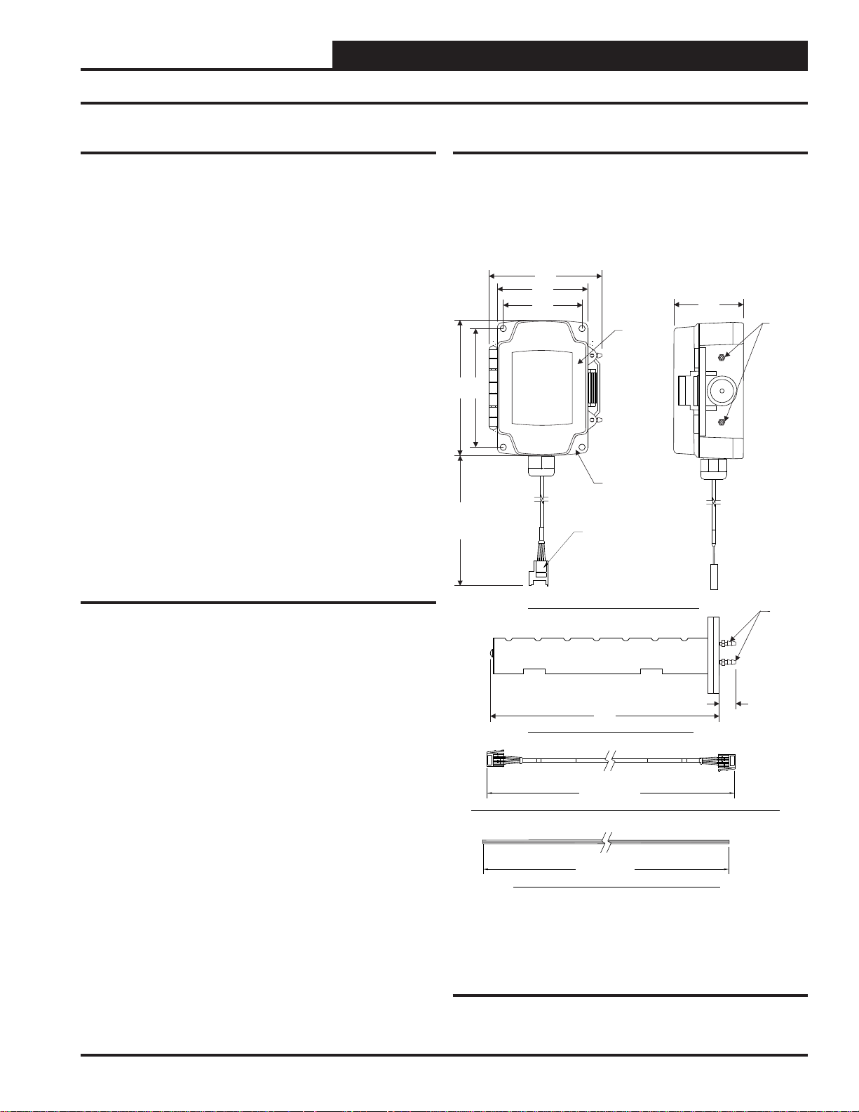
The OE256-07 Duct Mounted E-BUS CO2 Sensor with Remote Pickup
Tube
is used for monitoring duct CO2 levels and is designed for permanent mounting in the Return Air duct. It utilizes an aspiration box
to accurately capture CO2 levels in the duct. It connects to the VCB-X
Controller (OE335-23-VCBX) by using an E-BUS cable with E-BUS
connectors. See Figure 1 for dimensions.
The W all Mounted E-BUS CO2 Sensor (OE256-05) is used for monitoring space CO2 levels and is designed for permanent wall mounting in
the conditioned space. It connects to the VCB-X Controller using an
EBC E-BUS Expansion Cable. It can be daisy-chained with the E-BUS
Digital Room Sensor (OE217-02, OE217-03, OE217-04) for applications requiring both a space CO2 sensor and space temperature sensor.
For more information, refer to the OE256-05 W all Mounted CO2 Sensor
Technical Guide.
Some typical applications are:
Controlling ventilation in a building where the occupancy
varies frequently
Controlling ventilation to ensure excess outdoor air is not
causing energy waste
Ensuring good air distribution throughout building zones
Environmental Requirements
The Duct Mounted E-BUS CO2 Sensor needs to be installed in an
environment that can maintain a temperature range between 14°F and
122°F and a humidity range between 5% and 95% RH (non-condensing).
4.12"
3.31"
2.55”
BRASS
BARB
FITTINGS
FOR
0.170 I.D.
TUBING
5.00"
13.00"
APPROX.
4.06"
2.81”
HINGED
COVER
SENSOR
HOUSING
E-BUS CONNECTOR
FEMALE END
Features
The CO2 Sensor provides the following:
Uses the patented dual beam Non-Dispersive Infrared
(NDIR) technology
A very accurate and stable sensor guaranteed to maintain
its accuracy due to infrared self-calibration feature of sensor
Sensor accuracy of +/- 50 ppm @ 1000 ppm or 2% of the
measured value
Annual drift of +/- 2 ppm per year
Measurement range of 0 to 2000 ppm
HB LED under front cover shows active CO
sensing
2
™
4321
3M
CO2 SENSOR, HOUSING AND CABLE ASSEMBLY
CO2 PICKUP TUBE (PROVIDED WITH SENSOR)
3M
4321
E-BUS CONNECTOR EXTENSION CABLE WITH MALE ENDS (PROVIDED WITH SENSOR)
EBC-10F
0.170 I.D. TUBING (PROVIDED WITH SENSOR)FIRE RATED
8.25"
"WATTMASTER EBUS" "WATTMASTER EBUS"
120.00” APPROX.
120.00” APPROX.
EBC-10F
BRASS
BARB
FITTINGS
FOR
0.170 I.D.
TUBING
0.55”
3M
4321
Figure 1: Duct Mounted E-BUS CO2 Sensor with
Remote Pickup Tube Dimensions
Technical Guide
3
Page 4

Duct Mounted E-BUS CO2 Sensor Technical Guide
Duct Mounted E-BUS CO2 Sensor Installation
Duct Mounted CO2 Sensor Installation
To install the Duct Mounted E-BUS CO2 Sensor, please follow the instructions below. See Figure 2 for detailed illustrations of the Duct
Mounted E-BUS CO
STEP 1: Find the general location on the side of the Return Air
Duct where you want to mount the CO2 Sensor. Be sure to locate
the box with the airfl ow in the proper direction per the airfl ow
label. A conduit clamp is provided to help seal the opening where
the sensor cabling penetrates the aspiration box housing.
STEP 2: Connect the sensor’s attached cable which has a Jack
E-BUS connector to the provided EBC E-BUS Cable. Then connect the EBC E-BUS Cable to the VCB-X Controller or EBC Hub
or Adapter Board and to the VCB-X Controller.
STEP 3: Secure the sensor in its aspiration box assembly to the
ductwork with the (2) supplied sheet metal screws.
Sensor and its components.
2
STEP 4: Mount the remote pickup tube assembly separately to
the ductwork by fi rst cutting a 1
wall. Then insert the remote pickup tube into the hole. Secure
the remote pickup tube to the ductwork by inserting (2) supplied
sheet metal screws through the (2) mounting holes in the remote
pickup tube mounting plate and securing the remote pickup tube
assembly by screwing it to the ductwork using a manual or powered screw driver to tighten the screws.
STEP 5: Using the supplied 10 ft. long tubing, connect the
remote pickup tube to the aspiration box assembly, cutting the
tubing to fi t.
1
/4” diameter hole in the ductwork
4
Technical Guide
Page 5

Duct Mounted E-BUS CO2 Sensor Technical Guide
SECURE CO2 SENSOR
ASSEMBLY TO DUCT OR
UNIT HOUSING WITH
SHEET METAL SCREWS
(BY OTHERS)
Duct Mounted E-BUS CO2 Sensor Installation
CO2 SENSOR
ASSEMBLY
ROUTE
FIRE RATED 0.170 I.D.
TUBING FROM C02
PICKUP TUBE PORTS TO
SENSOR HOUSING PORTS
SUPPLIED
CO2 PICKUP
TUBE ASSEMBLY
CUT 1-1/4” DIAMETER
HOLE IN DUCT FOR CO2
PICKUP TUBE INSERTION
RETURN AIR
DUCT SIDE WALL
SECURE CO2 PICKUP TUBE
ASSEMBLY TO DUCT WITH
4321
3M
3M
4321
VCB-X CONTROLLER
SUPPLIED E-BUS
EXTENSION CABLE
CONNECTED BETWEEN
CO2 SENSOR E-BUS
CONNECTOR AND E-BUS
CONNECTOR ON VCB-X,
E-BUS HUB OR ADAPTER
BOARD
SUPPLIED SHEET METAL SCREWS
LOOPCOMM
485 DRV
T-
SH
LT1785
U
.1uF
R+
TB1
BINARY
INPUTS
P5
BIN1
D6
BIN2
D7
BIN3
D8
BIN4
R38
D9
30
COM
R41
30
R43
COM
30
R47
TB3
30
CUTTO ISOLATE
COM FROM GND
R1
R63
+3.3V
J1
+5V
GND
3650
R68
BACNET
485 DRV
T-
SH
4751
LT1785
R+
U2
.1uF
C81
TB7
ANALOG
INPUTS
AI1
AI2
AI3
AI4
AI5
GND
+12V
GND
TB4
GND
3650
R17
APPHB
3650
R20
OS HB
3650
R22
WDOG
SERIAL #
SERIAL #
4321
YS102442 REV 1
WATTMASTER CONTROLS
MADE IN USA
RLY1
RLY2
RLY3
RLY4
RLY5
RLY6
COMMON
TB2
RELAY
OUTPUTS
ALERT
R82
3650
24VAC
P2
DIGITAL
COMP
P3
UNLOAD
C30
ANALOG
1002
R51
OUTPUTS
2201
R59
U17
AOUT1
AOUT2
.1uF
AOUT3
C36
2201
R73
U19
GND
AOUT3AOUT1-2
GND
TB6
.1uF
STATUS 1
C46
STATUS 2
EBUS
POWER
3650
R21
3650
R109
R16
3650
R14
3650
.1uF
C21
ADDRESS
ADD
1002
1
1002
2
1002
4
1002
OFF
8
1002
16
1002
32
1002
BAUD
LOOP
1
1002
2
SW1
3M
C14
.01uF
Figure 2: Mounting and Cable Installation for Duct Mounted E-BUS CO2 Sensor
Technical Guide
5
Page 6

Duct Mounted E-BUS CO2 Sensor Technical Guide
Duct Mounted E-BUS CO2 Sensor Wiring to VCB-X Controller
Duct Mounted E-BUS CO2 Sensor
The OE256-07 Duct Mounted E-BUS CO2 Sensor with Remote Pickup
Tube is used for sensing the current CO2 level in the HV AC unit’ s return
air stream. This is useful when you want an average CO2 reading in the
area served by the HVAC unit or when you don’t want a wall mounted
E-BUS CO2 Sensor due to sensor tampering concerns in the space.
The OE256-07 Duct Mounted Return Air CO2 Sensor is comprised of
the CO2 Sensor, the W attMaster Aspiration Box Assembly , and a Remote
Pickup Tube. See the dimensional and installation information in Figur es
2 & 3 for mounting, wiring, and installation details.
Note:
1.) The Duct Mounted E-BUS CO Sensor
Connects To The Controller Using An
VCB-X
EBC E-BUS Cable Of The Required Length
Or The Provided 10 Foot EBC Cable.
OE256-07 Duct Mounted
E-BUS CO Sensor
2
2
The Duct Mounted Return Air E-BUS CO2 Sensor with Remote Pickup
Tube is designed to be mounted in the return air duct of the HVAC unit
and uses its integral aspiration box to sample the CO2 level in the duct.
See Figure 3 below for wiring and installation details.
NOTE: If using multiple E-BUS Sensors or Modules, the
E-BUS Hub or Adapter Board may be required.
RS-485 COMMUNICATION LOOP. WIRE
“R” TO “R”, “T” TO “T” “SHLD”TO “SHLD”
www.aaon.com
www.orioncontrols.com
VCB-X CONTROLLER
Orion No.:OE335-23-VCBX-A
ANALOG INPUTS
AI1 = SPC (SPACETEMPERATURE SENSOR)
= SAT(SUPPLY AIR TEMPERATURE SENSOR)
AI2
= OAT(OUTDOOR AIR TEMPERATURE SENSOR)
AI3
= DCT (DIGITALCOMP. DISCHARGE TEMPERATURE SENSOR)
AI4
AI5
= SPACETEMPERATURE SLIDE OFFSET
BINARY INPUTS
BI1
= EMERGENCY SHUTDOWN
BI2
= PROOF OF FLOW
BI3
= DIRTY FILTER
Bi4
= COIL TEMPERATURE SWITCH
G OUTPUTS
ANALO
AO1
= FAN VFD
AO2
= ECONOMIZER
AO3
= MOD. HEATING
TRIAC OUTPUT
TR1
= DIGITALCOMP.
UNLOADER
(24 VAC & UNLOAD
TERMINALS)
WattMaster Label
#LB102093-01-A
Rev.: 1B
24 VAC POWER
ONLY
WARNING!
POLARITY MUST
BE OBSERVED
OR THE
CONTROLLER
WILL BE
DAMAGED
GND
+24 VAC
STATUS LED BLINK CODES
LED NAME STATUS1 STATUS2
NORMAL OPERATION 0 1
SAT FAIL 1 2
OAT FAIL 2 2
SPC FAIL 3 2
MISSING EXP MODULE 4 2
CO2 SENSOR FAIL 6 2
AIRFLOW SENSORFAIL 7 2
MECH COOL FAIL 1 3
MECH HEATFAIL 2 3
FAN PROOF FAIL 3 3
DIRTY FILTER 4 3
EMERGENCY SHUTDOWN 5 3
LOW SAT 1 4
HIGH SAT 2 4
CONT. TEMPHI ALARM 3 4
CONT. TEMP LOALARM 4 4
HIGH HEAD PRESSURE 5 4
WATER PROOF FAILURE 6 4
SUCTION PRESSURE ALARM 7 4
LOW LEAVING WATER TEMP 8 4
E-BUS
EXPANSION
RELAYCONTACT
RATING IS 1AMP
MAX @ 24 VAC
FAN
RELAY2
RELAY3
RELAY4
RELAY5
RELAY6
RELAY
COMMON
AAON No.:
V04740
ALERT LED BLINKCODES BLINKS
NORMAL OPERATION 0
MISSINGOR SHORTED
DISCHARGE TEMP. SENSOR
IN 30 MIN. CUTOFF PERIOD 3
IN HIGH TEMP. CUTOFF 4
COMPRESSOR LOCKEDO UT 6
E-BUS
EXPANSION
MADE IN USA
1
VCB-X Controller
4 3 2 1
1.2
37X04
3M
<PC>
1.6
EBC E-BUS
Cable
with Jack
Connection
10 Foot EBC
E-BUS Cable
(Provided)
Figure 3: Duct Mounted E-BUS CO2 Sensor & Digital Room Sensor Wiring for VCB-X Controller
6
Technical Guide
Page 7

Duct Mounted E-BUS CO2 Sensor Technical Guide
Using LEDs to Troubleshoot
LEDs are available for troubleshooting the CO2 Sensor. There are two
LEDs that are visible at an angle through the plastic cover. See Figure
4 for locations.
COMM LED
The COMM LED blinks on whenever communications are sensed.
HB LED
Initially, the HB LED blinks fast for 30 seconds. It will then blink every
30 seconds. A CO2 sample is taken once every 30 seconds.
HB
LED
COMM
LED
Troubleshooting
R+
G
+12
T -
Altitude Correction
Altitude correction can be confi gured using Prism II software installed
on a computer. The altitude can be confi gured at a value of 0-15,000
feet. The default is 500 feet.
TB1 Terminal Block (CO2 Reading)
The TB1 terminal block should only be used to test the sensor when the
sensor cable is plugged into the controller and the sensor and controller
are powered up. Directions: Set the meter for DC volts and connect
the GND probe to the GND terminal and the + probe to the CO2 0-5
terminal. Look at the output voltage and record it. Multiply the voltage
times 400. The value should match the CO2 as read on the System Manager TS, Modular System Manager, Modular Service Tool, or Prism. If
the signal doesn’t match the sensor reading, call WattMaster Controls
for a replacement.
J1
Figure 4: OE256-07 Board LEDs
Technical Guide
7
Page 8

Form: OR-DM-EBUS-CO2-TGD-01A Printed in the USA May 2012
All rights reserved. Copyright 2012
WattMaster Controls Inc. 8500 NW River Park Drive Parkville, MO 64152
Phone: 866-918-1100 www.orioncontrols.com Fax (816) 505-1101
 Loading...