

Page 1
www.orioncontrols.com
OE256-05 Wall Mounted
E-BUS CO
Technical Guide
Sensor
2
Page 2
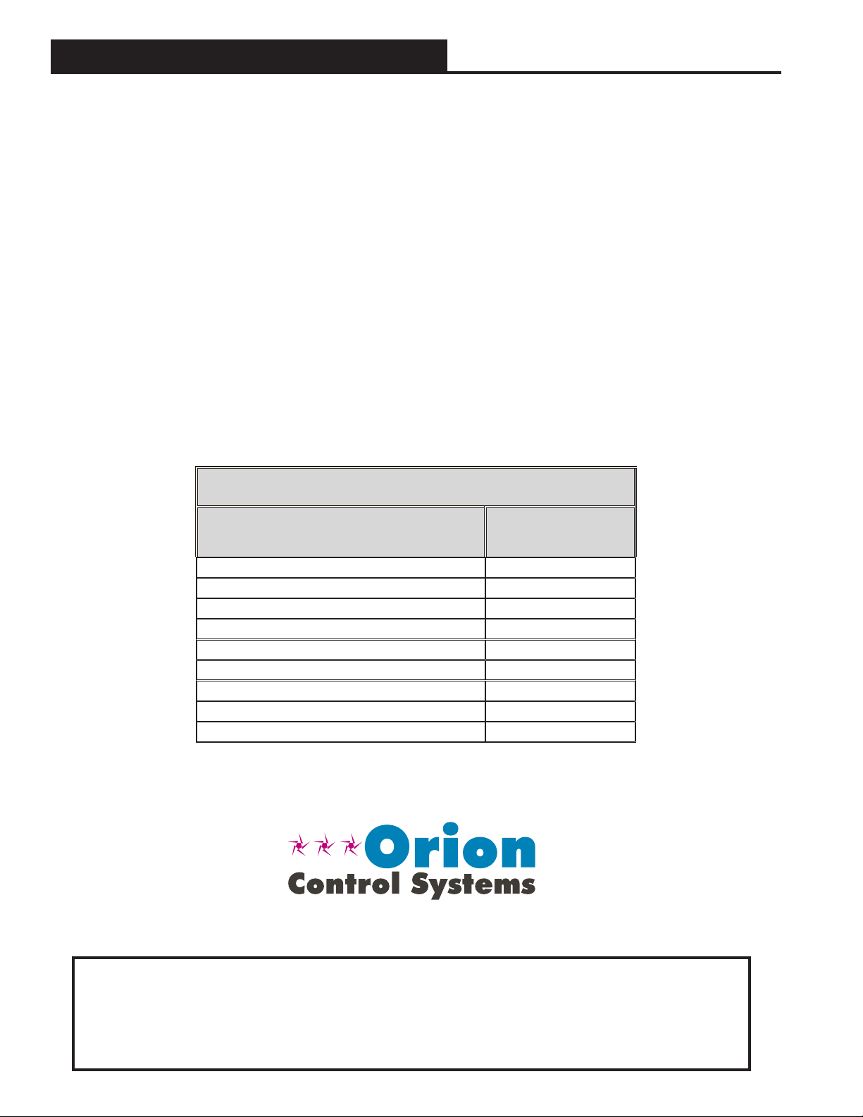
TABLE OF CONTENTS
SENSOR OVERVIEW ......................................................................................................................................... 3
Features .......................................................................................................................................................................................3
Environmental Requirements ....................................................................................................................................................... 3
WALL MOUNTED E-BUS CO
SENSOR WIRING TO HVAC UNIT CONTROLLER ............................................... 4
2
TROUBLESHOOTING ........................................................................................................................................ 5
Setting The Sensor Address Switch .............................................................................................................................................5
Using LEDs to Troubleshoot ........................................................................................................................................................6
Altitude Correction ........................................................................................................................................................................6
TB1 Terminal Block (CO2 Reading) ..............................................................................................................................................6
APPENDIX ........................................................................................................................................................ 7
Mounting Plate Dimensions..........................................................................................................................................................7
PART NUMBER CROSS REFERENCE TABLE
PART DESCRIPTION PART NUMBER
Wall Mounted E-BUS CO
Duct Mounted E-BUS CO2 Sensor OE256-07
E-BUS LCD Digital Room Sensor Temp Only OE217-02
E-BUS LCD Digital Room Sensor Temp & RH OE217-03
E-BUS Digital Room Sensor Temp & RH OE217-04
Mounting Plate BK000081
EBC E-BUS Cables - varying lengths EBC-XXXF
VCB-X Controller OE335-26B-VCBX
VCC-X Controller OE338-26B-VCCX
Sensor OE256-05
2
WattMaster Controls Inc.
8500 NW River Park Drive · Parkville , MO 64152
Toll Free Phone: 866-918-1100
PH: (816) 505-1100 · FAX: (816) 505-1101 ·
E-mail: mail@wattmaster.com
Visit our web site at www.orioncontrols.com
www.orioncontrols.com
Form: OR-WM-EBUS-CO2-TGD-01B
Copyright December 2014 WattMaster Controls, Inc.
®
is a registered trademark of AAON, Inc., Tulsa, OK.
AAON
WattMaster Controls, Inc. assumes no responsibility for errors or
omissions.
This document is subject to change without notice.
Page 3
WALL MOUNTED E-BUS CO
Sensor Overview
SENSOR
2
Overview
The OE256-05 Wall Mounted E-BUS CO2 Sensor is used for monitoring
space CO
conditioned space. It connects to the VCB-X Controller (OE335-23-
VCBX) and VCC-X Controller (OE338-26B-VCCX) using an EBC
E-BUS Expansion Cable. It can be daisy-chained with the E-BUS
Digital Room Sensor (OE217-02, OE217-03, OE217-04) for applications requiring both a space CO2 sensor and space temperature sensor.
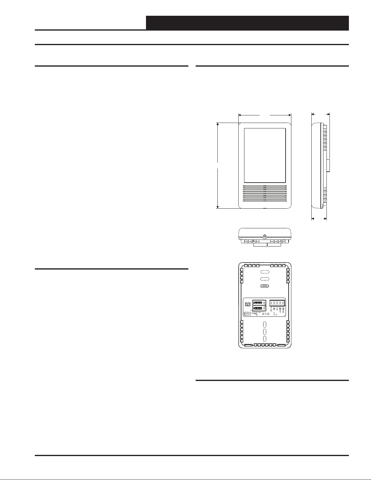
See Figure 1 for dimensions.
The OE256-07 E-BUS Duct Mounted CO2 Sensor with Remote Pickup
utilizes an aspiration box. It is used for sensing the current CO2 level in
the HVAC unit’s return air stream. It is designed to be mounted in the
return air duct of the HVAC unit and uses its integral aspiration box to
sample the CO2 level in the duct.
This technical guide provides information for the Wall Mounted E-BUS
CO2 Sensor only, for more information regarding the Duct Mounted EBUS CO2 Sensor, please see the OE256-07 Duct Mounted E-BUS CO2
Sensor Technical Guide.
Some typical applications are:
levels and is designed for permanent wall mounting in the
2
Controlling ventilation in a building where the occupancy
varies frequently
Controlling ventilation to ensure excess outdoor air is not
causing energy waste
Ensuring good air distribution throughout building zones
Environmental Requirements
The E-BUS CO2 Sensor needs to be installed in an environment that can
maintain a temperature range between 14°F and 122°F and a humidity
range between 5% and 95% RH (non-condensing).
2.80
4.54
0.96
0.80
Features
The CO2 Sensor provides the following:
Uses the patented dual beam Non-Dispersive Infrared
(NDIR) technology
A very accurate and stable sensor guaranteed to maintain
its accuracy due to infrared self-calibration feature of sensor
Sensor accuracy of +/- 50 ppm @ 1000 ppm or 2% of the
measured value
Annual drift of +/- 2 ppm per year
Measurement range of 0 to 2000 ppm
LED under front cover shows active CO
sensing
2
Addressable based on function within the system
™
Figure 1: Wall Mounted E-BUS CO2 Sensor
Dimensions
Technical Guide
3
Page 4

WALL MOUNTED E-BUS CO2 SENSOR
Wall Mounted Space CO2 Sensor Wiring to VCB-X Controller
Wall Mounting
The OE256-05 Wall Mounted E-BUS CO2 Sensor utilizes a sub-base
mounting plate with a modular phone jack providing quick and easy
mounting and wiring. The wall-mounted sensor’s sub-base is compatible with standard junction boxes. A locking screw secures the assembly
to the wall.
Optional Mounting Plate
Included with the Digital Room Sensor is a mounting plate that
can be used, if necessary, to cover the sensor sheet rock opening.
This mounting plate screws onto the back of the housing base.
The mounting plate is then mounted and covers the recessed space
in the wall. A locking screw secures the sensor to the wall. See
Figure 6, page 7 for dimensions.
OE256-05
Wall Mounted E-BUS
CO Sensor
2
NOTE: Mount Both
Sensors At Least
5 Feet Above Floor.
The Digital Room
Sensor Connects To
The Sensor.CO
2
Wiring to the VCB-X Controller
The OE256-05 Wall Mounted E-BUS CO2 Sensor connects to the
VCB-X or VCC-X Controller with an EBC E-BUS expansion cable. It
can be daisy-chained with the Digital Room Sensor (OE217-02, OE217-
03, OE217-04) for applications requiring both a space CO2 sensor and
space temperature sensor. Refer to Figure 2 for instructions (VCB-X
Controller shown).
VCB-X Controller
RS-485 COMMUNICATION LOOP. WIRE
RS-485 COMMUNICATION LOOP. WIRE
“R” TO “R”, “T” TO “T” “SHLD”TO “SHLD”
“R” TO “R”, “T” TO “T” “SHLD”TO “SHLD”
www.aaon.com
www.aaon.com
www.orioncontrols.com
www.orioncontrols.com
VCB-X CONTROLLER
VCX CONTROLLER
Orion No.:OE335-23-VCBX-A
Orion No.:OE335-23-VCX
ANALOG INPUTS
ANALOG INPUTS
AI1 = SPC (SPACETEMPERATURE SENSOR)
AI1 = SPC (SPACETEMPERATURE SENSOR)
= SAT(SUPPLY AIR TEMPERATURE SENSOR)
AI2
= SAT(SUPPLY AIR TEMPERATURE SENSOR)
AI2
= OAT(OUTDOOR AIR TEMPERATURE SENSOR)
AI3
= OAT(OUTDOOR AIR TEMPERATURE SENSOR)
AI3
= DCT (DIGITALCOMP. DISCHARGE TEMPERATURE SENSOR)
AI4
= DCT (DIGITALCOMP. DISCHARGE TEMPERATURE SENSOR)
AI4
= SPACETEMPERATURE SLIDE OFFSET
AI5
= SPACETEMPERATURE SLIDE OFFSET
AI5
BINARY INPUTS
BINARY INPUTS
= EMERGENCY SHUTDOWN
BI1
= EMERGENCY SHUTDOWN
BI1
= PROOF OF FLOW
BI2
= PROOF OF FLOW
BI2
= DIRTY FILTER
BI3
= DIRTY FILTER
BI3
= COIL TEMPERATURE SWITCH
Bi4
I
= REMOTE OCCUPIED OR COIL TEMPERATURE SWITCH
B4
G OUTPUTS
ANALO
ANALOG OUTPUTS
= FAN VFD
AO1
= FAN VFD
AO1
= ECONOMIZER
AO2
= ECONOMIZER
AO2
= SCR OR MODULATING HW HEATING
AO3
= SCR OR MODULATING HW HEATING
AO3
TRIAC OUTPUT
TRIAC OUTPUT
= DIGITALCOMP. UNLOADER
TR1
= DIGITALCOMP. UNLOADER (24 VAC & UNLOAD TERMINALS)
TR1
(24 VAC & UNLOADTERMINALS)
WattMaster Label
WattMaster Label
#LB102093-01-A
#LB102093-01-A
Rev.: 1A
Rev.: 1C
24 VAC POWER
ONLY
24 VAC POWER
WARNING!
ONLY
POLARITY MUST
WARNING!
BE OBSERVED
POLARITY MUST
OR THE
BE OBSERVED
CONTROLLER
OR THE
WILL BE
CONTROLLER
DAMAGED
WILL BE
DAMAGED
GND
24 VAC
INPUT
+24 VAC
STATUS LEDBLINK CODES
LED NAME STATUS1 STATUS2
LED NAME STATUS1 STATUS2
NORMAL OPERATION 0 1
NORMAL OPERATI ON 0 1
SAT FAIL 1 2
SATFAIL 1 2
OAT FAIL 2 2
OATFAIL 2 2
SPC FAIL 3 2
SPC FAIL 3 2
AIRFLOW SENSORFAIL 7 2
MECHCOOL FAIL 1 3
MECH COOL FAIL 1 3
MECHHEAT FAIL 2 3
MECH HEAT FAIL 2 3
FANPROOF FAIL 3 3
FAN PROOFFAIL 3 3
DIRTY FILTER 4 3
DIRTY FILTER 4 3
EMERGENCY SHUTDOWN 5 3
EMERGENCYSHUTDOWN 5 3
LOW SAT 1 4
LOW SAT 1 4
HIGH SAT 2 4
HIGHSAT 2 4
CONT. TEMPC OOLFAIL 3 4
CONT. TEMP COOL FAIL 3 4
CONT.TEMP HEAT FAIL 4 4
CONT. TEMP HEAT FAIL 4 4
PUSH BUTTONOVR 1 5
PUSH BUTTON OVR 1 5
OUTPUT FORCE ACTIVE 0 6
OUTPUTFORCE ACTIVE 0 6
E-BUS
E-BUS
EXPANSION
EXPANSION
RELAYCONTACT
RELAYCONTACT
RATING IS 1AMP
RATING IS 1AMP
MAX @ 24 VAC
MAX @ 24 VAC
RELAY
COMMON
RELAY2
RELAY3
RELAY2
RELAY3
RELAY4
RELAY4
RELAY5
RELAY5
RELAY6
RELAY
RELAY6
COMMON
AAON No.:
V04740
ALERT LEDBLINK CODES BLINKS
NORMAL OPERATION 0
MISSING OR SHORTED
DISCHARGE TEMP. SENSOR
IN 30 MIN. CUTOFF PERIOD 3
IN HIGH TEMP. CUTOFF 4
COMPRESSOR LOCKED OUT 6
LED BLINKCODES
EXPANSION
EXPANSION
E-BUS
E-BUS
FAN
FAN
MADE IN USA
1
OVERRIDE ALARM
Display
Override
EBC E-BUS Cable
EBC E-BUS Cable
OE217-02, OE217-03, OE217-04
E-BUS Digital Room Sensor
Figure 2: Wall Mounted Space E-BUS CO2 Sensor & Digital Room Sensor Wiring for VCB-X Controller
4
Technical Guide
Page 5

WALL MOUNTED E-BUS CO
Setting the Address Switch
SENSOR
2
Addressing & LEDs On/Off
The Wall Mounted E-BUS CO2 Sensor is equipped with binary dipswitches. The Address Switch is located on the Sensor’s board and is
only visible by taking the device off the wall and removing the back
cover. See location in Figure 3. The default addresses are as follows:
• Space or Return CO2 Sensor = Address 1
• Supply CO2 Sensor = Address 2 (Future)
• Open addresses for Custom Applications = 3-15
• LEDs On = Dipswitch 8 ON
NOTE:
Power Up The VCB-X or VCC-X Controller That The C Sensor Is
Connected To Before Setting the C Sensor’s Address Switch In
Order For Any Changes To Take Effect. Default Is Address 1. If Using
Only One C Sensor, There Is No Reason To Change The Address.
O
2
O
2
ADD
O
2
NOTE: If you forget to set the address, and all dipswitches are
off, the address will default to address 1.
To set the address, follow these instructions:
1. Power up the VCB-X or VCC-X Controller that the Sensor
is plugged into.
2. Set the Dipswitch to the proper setting.
3. The address range can be set from 1 to 15.
4. To verify that the correct address has been entered,
refer to the STATUS LED information on page 6.
The board address is stored in nonvolatile memory. Once the address is
set, the address will be saved after loss of power. See Figure 3 below
for address switch setting information.
1
2
4
8
Not Used
Not Used
Not Used
LEDs ON
ADD
O
2
O
2
Address Switch Shown Is
Set For Address 1
C SensorO
2
If Using More Than One C Sensor,
The Address For Each C Sensor
Must Be Unique From The Others.
This Feature Is For Future Use.
Address Switch
Figure 3: Setting the Address and LEDs On/Off Option
E-BUS C Sensor with Back Cover RemovedO
PIC32MX440F
MICROCHIP
512H-80I/PT
2
Technical Guide
5
Page 6

WALL MOUNTED E-BUS CO2 SENSOR
Troubleshooting
Using LEDs to Troubleshoot
LEDs are available for troubleshooting the CO2 Sensor. The LEDs are
ON when Dipswitch 8 is on. The LEDs are off when Dipswitch 8 is off.
The Front LED is visible through the front cover of the CO2 Sensor. See
Figure 5 for location. The other LEDs are located on the Sensor’s board
and are only visible by taking the device off the wall and removing the
back cover. See Figure 4 for locations.
Front LED
When the LEDs are turned on, a green LED will be visible through the
front plastic cover of the CO2 sensor. See Figure 5. The Front LED
will blink whenever a CO2 sample is taken. A sample is taken every
30 seconds.
STATUS LED
Initially, the STATUS LED blinks fast for 30 seconds. It then stays on
and blinks the board address whenever a CO2 sample is taken. A CO2
sample is taken once every 30 seconds.
COMM LED
The COMM LED blinks on whenever communications are sensed.
ADDRESS SWITCH
STATUS LED
COMM LED
512H-80I/PT
PIC32MX440F
MICROCHIP
Altitude Correction
Altitude correction can be confi gured using Prism 2 software installed
on a computer. The altitude can be confi gured at a value of 0-15,000
feet. The default is 500 feet.
TB1 Terminal Block (CO2 Reading)
The TB1 terminal block should only be used to test the sensor when the
sensor cable is plugged into the controller and the sensor and controller
are powered up. Directions: Set the meter for DC volts and connect
the GND probe to the GND terminal and the + probe to the CO2 0-5
terminal. Look at the output voltage and record it. Multiply the voltage
times 400. The value should match the CO2 as read on the System Manager TS, Modular System Manager, Modular Service Tool, or Prism. If
the signal doesn’t match the sensor reading, call WattMaster Controls
for a replacement.
Figure 4: Address Switch and Board LEDs
Figure 5: Wall Mounted E-BUS CO2 Sensor’s Front
LED
6
Technical Guide
Page 7

WALL MOUNTED E-BUS CO
1.638
1.810
0.882
1.407
1.842
0.733
2.110
2.920
0.810
R0.220
3.275
0.060
0.160
5.037
3.278
3.766
4.153
Appendix - Mounting Plate Dimensions
Optional Mounting Plate
Included with the Digital Room Sensor is a mounting plate that
can be used, if necessary, to cover the sensor sheet rock opening.
This mounting plate screws onto the back of the housing base.
The mounting plate is then mounted and covers the recessed space
in the wall. A locking screw secures the sensor to the wall. See
Figure 6, below for dimensions.
SENSOR
2
Figure 6: BK000081 Mounting Plate Dimensions
Technical Guide
7
Page 8

Form: OR-WM-EBUS-CO2-TGD-01B Printed in the USA December 2014
All rights reserved. Copyright 2014
WattMaster Controls Inc. 8500 NW River Park Drive Parkville, MO 64152
Phone: 866-918-1100 www.orioncontrols.com Fax (816) 505-1101
 Loading...