

Page 1
Description
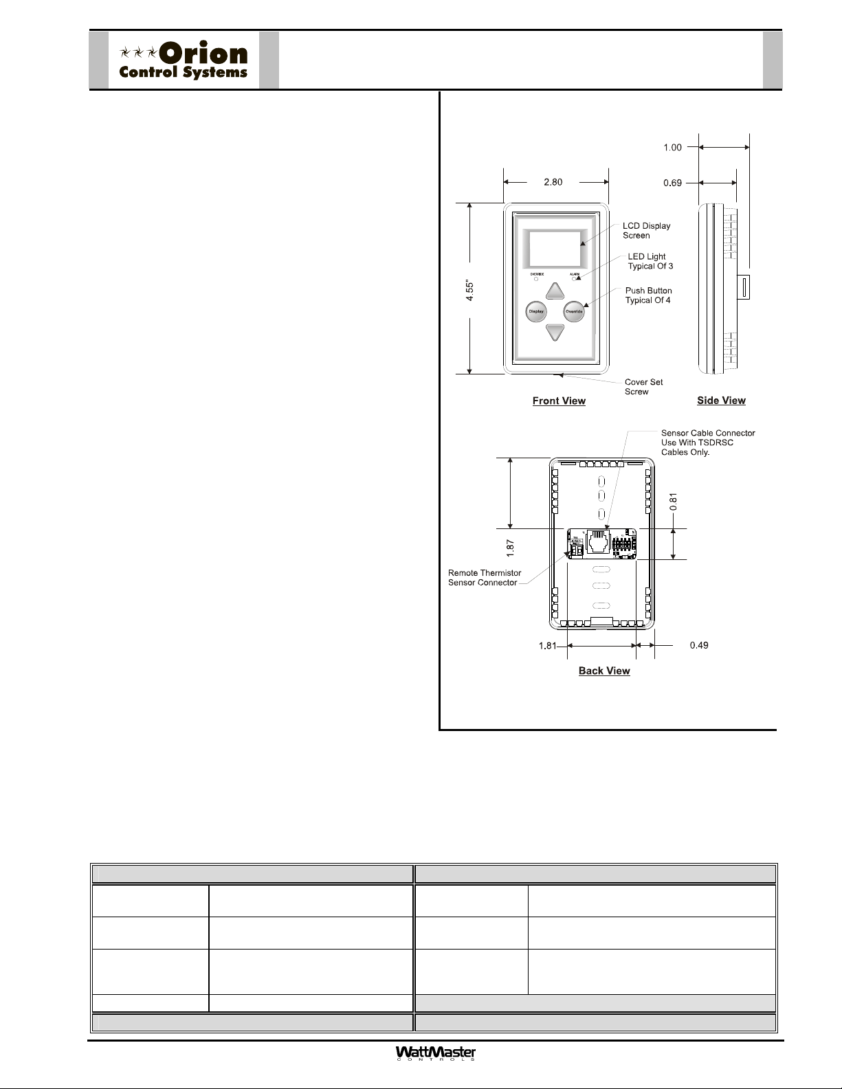
The OE217 series of Touch Screen Digital Room Sensors
are used to sense Space Temperature only or Space
Temperature & Space Humidity. The OE217-00 model is
the Space Temperature Sensor only model and can be
used with the VCM-X Controller (OE332-23-VCMX) and
the VAV/Zone Controller (OE324-02). The OE217-01 is a
combination Space Temperature & Space Humidity
Sensor model and can only be used with the VCM-X
Controller.
Besides sensing Temperature & Humidity, the Digital
Room Sensors also provide these other useful features:
• User Friendly Graphical LCD Display with LED
Backlight
• Display the Current Space and Outdoor Air
Temperature
• Display the Current Space Humidity and Outdoor
Air Relative Humidity (OE217-01 Model Only)
OE217-00 & OE217-01
Digital Room Sensors
• Display the current Zone Setpoint Temperature
• Equipped With Push Buttons for Changing the
Zone Setpoint Temperature
• Equipped With an Override Button for Forcing the
VAV/Zone Controller or VCM-X Controller into
Occupied Operation from Unoccupied Operation
•
Provides graphics to indicate the mode of operation
• Provides LEDs to indicate Schedule Override,
Button Push, and Alarms
Both sensors connect to the controllers using TSDRSC
modular cables of multiple lengths connected between the
controller and the sensor. The TSDRSC modular cables
should not run in conduit with other AC line voltage wiring
or with any conductors carrying highly inductive loads.
Mounting
The Digital Room Sensor is designed to be mounted to a vertical, 2” x 4” electrical box recessed in the wall. If the wall
cannot be penetrated, a plastic surface mount box such as those made by Wiremold
sensor to the wall surface. The Sensor is mounted by removing the front cover and fastening the housing base to the
electrical box using the supplied (2) 6/32” x 1” machine screws. The Modular cable is then plugged into the phone jack
located on the circuit board that is mounted on the cover. The cover is then placed onto the housing base and the Allen
Screw on the bottom of the base is adjusted to hold the cover in place.
TM
, may be used to mount the
Technical Data OE217-00 & OE217-01 Digital Room Sensor
Sensor Element Type III Thermistor 10k ohm
@ 77 F Digital Sensing Device
Sensor Reading
Range
Ambient
Temperature
Limits
Accuracy
Three Year Warranty WattMaster reserves the right to change specifications without notice
Form: ORION-OE217-01-DigitalRoomSensor-1C.doc Page 1 of 1
RH +/-2%, Temp +/- .5F
40F to 120F
RH = 0-100%
-40F to 180F
Display 112 x 64 Monochrome Graphical LCD
w/LED Backlight
Connection
Weight
RJ-45 Modular Female Jack
3.2 oz.
Page 2
Description
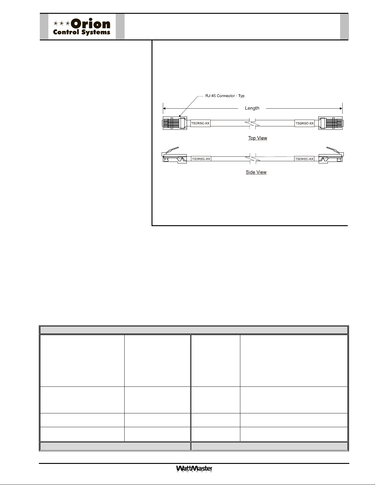
Digital Sensor Cable
TSDRSC-XX
The TSDRSC Cables are used to
connect power and communications between the WattMaster Digital Room Sensor or Digital CO
2
Sensor and the VCM-X Controller
or VAV/Zone Controller.
The TSDRSC Cables are prefabricated plenum-rated cables with RJ45 Connectors on both ends of the
cable for connection between the
Digital Room Sensor, Digital CO
2
Sensor, and the VCM-X or
VAV/Zone Controller.
The TSDRSC Cables are labeled
near each end with the cable part
number.
The TSDRSC Cables are available
in 5, 10, 15, 25, 40, 80, 120 & 160
feet lengths. These lengths should
satisfy most job requirements. For length requirements other than those listed, the MS000029 Modular
Room Sensor Cable Coupler can be used to connect two of the TSDRSC Cables together to provide
for your specific-length requirements.
The plug-in design of the TSDRSC Cables eliminates costly wiring errors and makes system installation easy. The cable components are all UL approved.
Technical Data TSDRSC Digital Sensor Cables
TSDRSC Cable Available
Lengths and Part Numbers
Cable Type Plenum-rated Wire Colors Brown, Blue, White W/ Blue Stripe, White
Wire Size 24 AWG Stranded
Terminations (2) RJ-45
Three Year Warranty
Form: ORION-ModularCable-TSDRSC-1A.doc Page 1 of 1
TSDRSC-5 (5 Ft.)
TSDRSC-10 (10 Ft.)
TSDRSC-15 (15 Ft.)
TSDRSC-25 (25 Ft.)
TSDRSC-40 (40 Ft.)
TSDRSC-80 (80 Ft.)
TSDRSC-120 (120 Ft.)
TSDRSC-160 (160 Ft.)
8 Conductor
Connectors
Current Rating of
Cable Wire
UL Listing No. CMP-UL As Per UL 910
Cable Sheath
Color
WattMaster reserves the right to change specifications without notice
24 AWG Wire = 0.577 Amps
(Maximum Amps
For Power Transmission)
W/ Brown Stripe, Orange,
White W/ Orange Stripe, Green,
White W/ Green Stripe
Gray
Page 3
Description
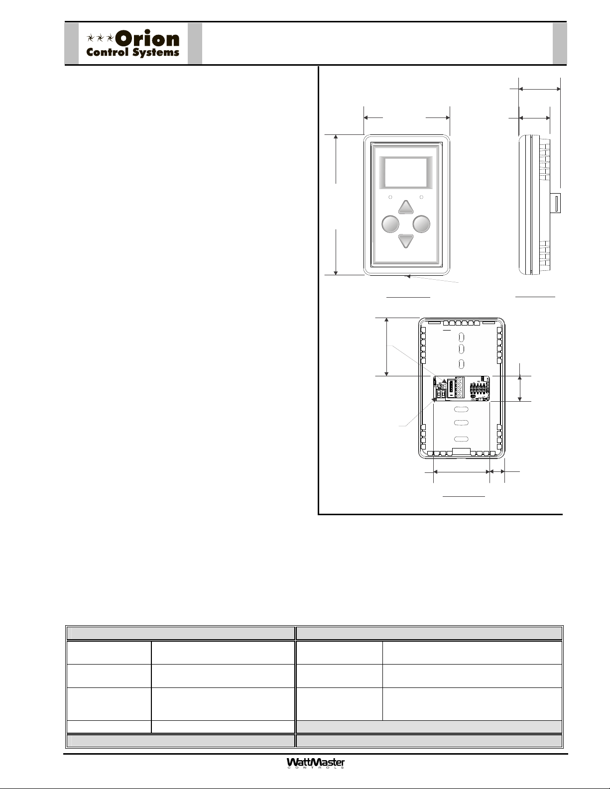
The OE217 series of Touch Screen E-BUS Digital Room
Sensors are used to sense Space Temperature only or
Space Temperature & Space Humidity. The OE217-02
model is the Space Temperature Sensor only model and
can be used with the VCB-X Controller (OE335-23-VCBX)
and the VAV/Zone Controller (OE3XX-0X). The OE217-03
is a combination Space Temperature & Space Humidity
Sensor model and can only be used with the VCB-X
Controller.
Besides sensing Temperature & Humidity, the E-BUS
Digital Room Sensors also provide these other useful
features:
• User Friendly Graphical LCD Display with LED
Backlight
• Display the Current Space and Outdoor Air
Temperature
• Display the Current Space Humidity and Outdoor
Air Relative Humidity (OE217-03 Model Only)
OE217-02 & OE217-03
E-BUS Digital Room Sensors
1.00
4.55”
2.80
OVERRIDE ALARM
Display
Override
Front View
Cover Set
Screw
0.69
Side View
• Display the current Zone Setpoint Temperature
• Equipped With Push Buttons for Changing the
E-BUS Cable
Connection
MICROCHIP
256GP206
PIC24HJ
0.81
Zone Setpoint Temperature
SHLD
-COM
• Equipped With an Override Button for Forcing the
VAV/Zone Controller or VCB-X Controller into
Occupied Operation from Unoccupied Operation
•
Provides graphics to indicate the mode of operation
1.87
Remote Thermistor
Sensor Connector
GND
+12Vdc
• Provides LEDs to indicate Schedule Override,
Button Push, and Alarms
Both sensors connect to the controllers using E-BUS
cables of multiple lengths connected between the
1.81
Back View
0.49
controller and the sensor. The E-BUS cables should not
run in conduit with other AC line voltage wiring or with any
conductors carrying highly inductive loads.
Mounting
The Digital Room Sensor is designed to be mounted to a vertical, 2” x 4” electrical box recessed in the wall. If the wall
cannot be penetrated, a plastic surface mount box such as those made by Wiremold
sensor to the wall surface. The Sensor is mounted by removing the front cover and fastening the housing base to the
electrical box using the supplied (2) 6/32” x 1” machine screws. The E-BUS cable is then plugged into the E-BUS
connector located on the circuit board that is mounted on the cover. The cover is then placed onto the housing base
and the Allen Screw on the bottom of the base is adjusted to hold the cover in place.
Technical Data OE217-02 & OE217-03 E-BUS Digital Room Sensor
Sensor Element Type III Thermistor 10k ohm
@ 77 F Digital Sensing Device
Sensor Reading
Range
Ambient
40F to 120F
RH = 0-100%
-40F to 180F
Temperature
Limits
Accuracy
Three Year Warranty WattMaster reserves the right to change specifications without notice
RH +/-2%, Temp +/- .5F
Display 112 x 64 Monochrome Graphical LCD
Connection
Weight
TM
, may be used to mount the
w/LED Backlight
E-BUS
3.2 oz.
Form: ORION-OE217-02-03-EBUS-DRS-1A.doc Page 1 of 1
Page 4
Description
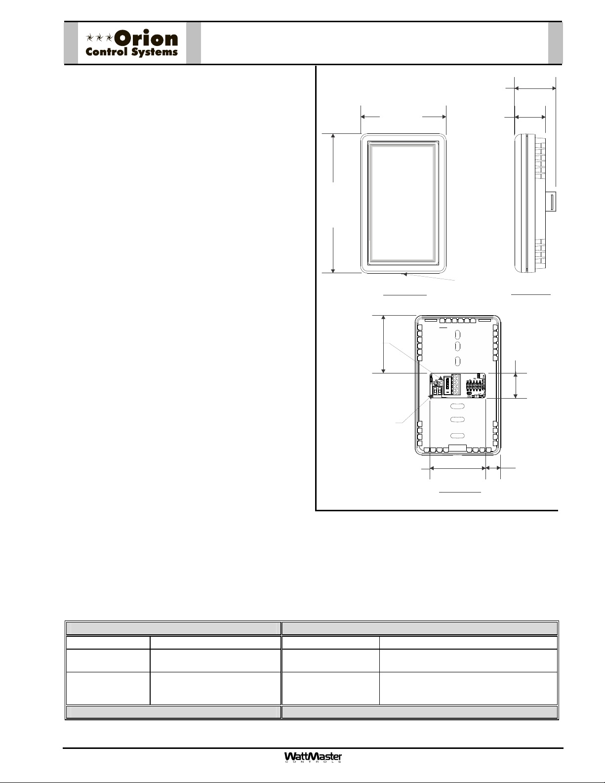
The OE217-04 E-BUS Digital Room Space & Humidity
Sensor is used to sense Space Temperature & Space
Humidity. The E-BUS Digital Room Sensor can be
used with the VCB-X Controller (Orion Part No.
OE335-23-VCB-X; AAON Part No. V04740).
The E-BUS Digital Room Sensor connects to the
controller using E-BUS cables of multiple lengths
connected between the controller and the sensor. The
E-BUS cables should not run in conduit with other AC
line voltage wiring or with any conductors carrying
highly inductive loads.
Mounting
The E-BUS Digital Room Sensor is designed to be
mounted to a vertical, 2” x 4” electrical box recessed in
the wall. If the wall cannot be penetrated, a plastic
surface mount box such as those made by
Wiremold
wall surface. The Sensor is mounted by removing the
front cover and fastening the housing base to the
electrical box using the supplied (2) 6/32” x 1” machine
screws. The E-BUS cable is then plugged into the EBUS connector located on the circuit board that is
mounted on the cover. The cover is then placed onto
the housing base and the Allen Screw on the bottom of
the base is adjusted to hold the cover in place.
TM
, may be used to mount the sensor to the
OE217-04
E-BUS Digital Room Sensor
1.00
4.55”
E-BUS Cable
Connection
Remote Thermistor
Sensor Connector
2.80
Front View
1.87
MICROCHIP
256GP206
PIC24HJ
Cover Set
Screw
SHLD
-COM
GND
+12Vdc
0.69
Side View
0.81
1.81
Back View
0.49
Technical Data OE217-04 E-BUS Digital Room Sensor
Sensor Element Digital Sensing Device Accuracy
Sensor Reading
Range
Ambient
40F to 120F
RH = 0-100%
-40F to 180F
Connection
Weight
Temperature
Limits
Three Year Warranty WattMaster reserves the right to change specifications without notice
RH +/-2%, Temp +/- .5F
E-BUS
3.2 oz.
Form: ORION-OE217-04-EBUS-DRS-1A.doc Page 1 of 1
Page 5
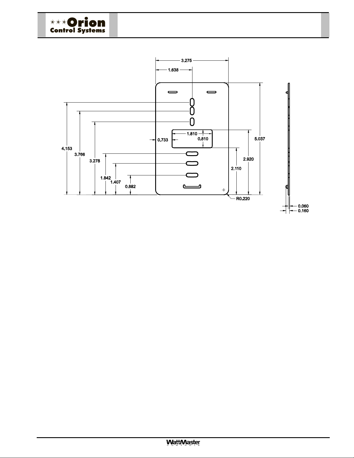
BK000081 – Sensor Mounting Plate
Description
The BK00081 Sensor Mounting Plate is used, if necessary, to cover the Sensor sheet rock opening. It
is provided with the following Sensors:
• OE217-00 - Digital Room Temperature Sensor
• OE217-01 - Digital Room Temperature and Humidity Sensor
• OE217-02 - E-BUS Digital Room Temperature Sensor
• OE217-03 - E-BUS Digital Room Temperature and Humidity Sensor
• OE217-04 - E-BUS Digital Room Temperature Sensor (No LCD Display)
• OE256-01 - Wall Mounted CO
• OE256-05 - E-BUS Wall Mounted CO
Sensor
2
Sensor
2
Mounting
The Mounting Plate screws onto the back of the Sensor’s housing base. The mounting plate is then
mounted and covers the recessed space in the wall. A locking screw secures the Sensor to the wall.
Form: ORION-BK000081-Sensor-Mounting-Plate-1A.doc Page 1 of 1
Page 6

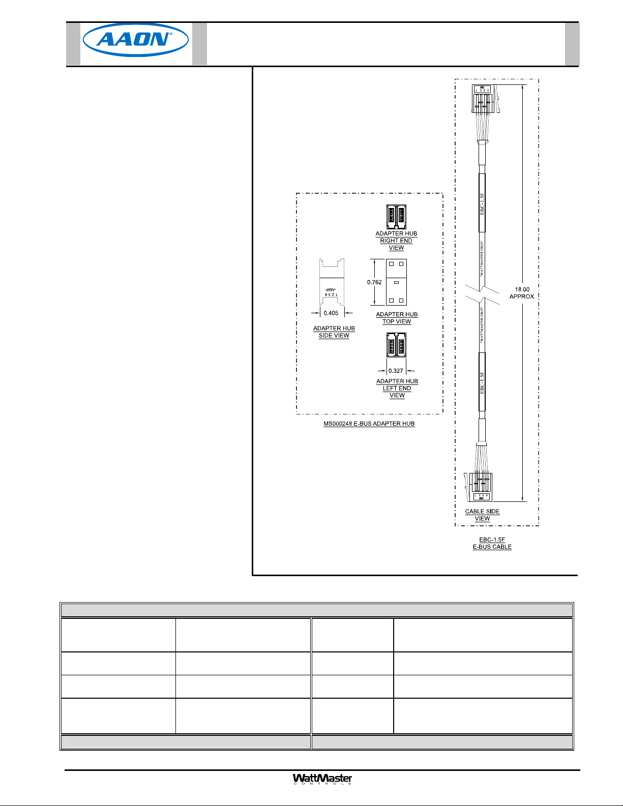
MS000248 - E-BUS Adapter Hub
Description
The MS000248 E-BUS Adapter
Hub is used to provide a
connection point for multiple EBUS Sensors or Modules. This EBUS Adapter Hub has four
ports. One port is used to connect
the Hub to an E-BUS Expansion
Port on the VCB-X Controller or a
VCB-X Expansion Module using
EBC E-BUS cables. This leaves
three ports available for E-BUS
Sensors and other Modules.
The EBC Cables are plenum-rated
high flex wire cables with an EBC
Connector on each end of the
cable for connection between the
Sensors, Modules, and the VCB-X
Controller.
ADAPTER HUB
RIGHT END
-AMP
1234
0.405
ADAPTER HUB
SIDE VIEW
MS000248 E-BUS ADAPTER HUB
0.762
ADAPTER HUB
TOP VIEW
ADAPTER HUB
LEFT END
VIEW
0.327
VIEW
Technical Data MS000248 E-BUS Adapter Hub
Terminations Hub - (4) EBC Connectors
Three Year Warranty
WattMaster reserves the right to change specifications without notice
.
Form: AAON-MS000248-E-BUS-Adapter-1A.doc Page 1 of 1
Page 7
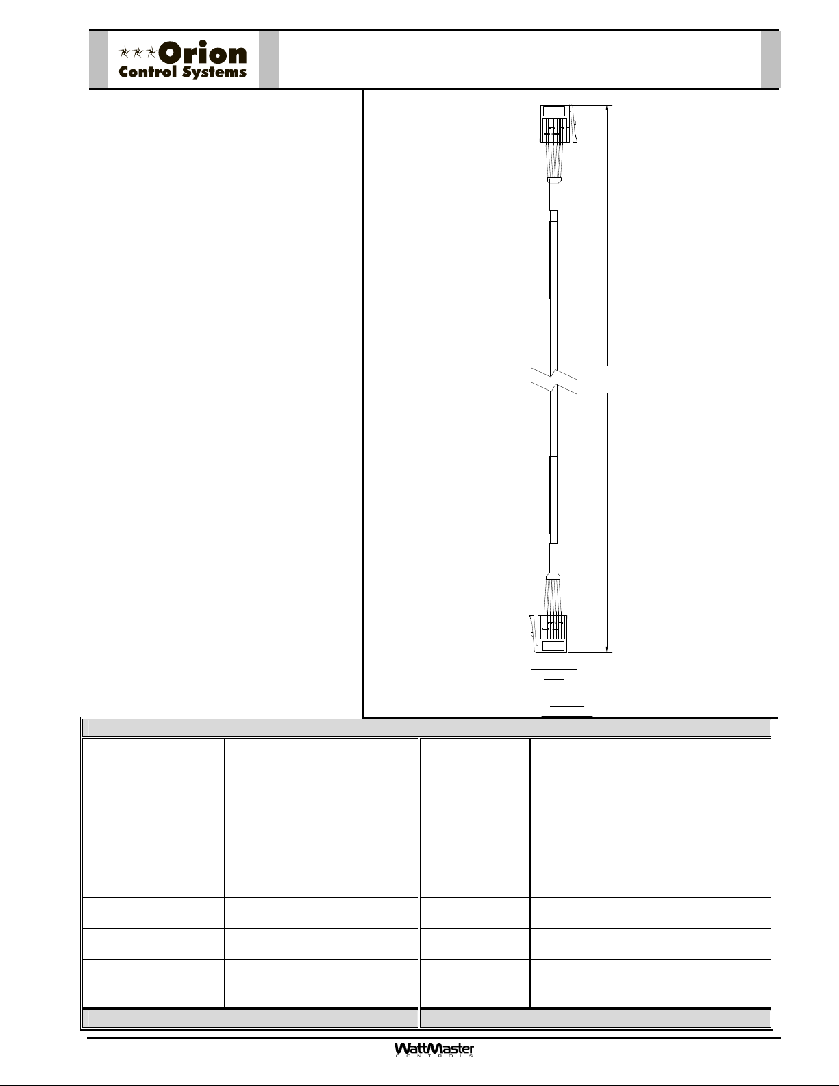
Description
The HZ-EBC-248 (AAON Part No.
V17180)
MS000248 E-BUS Adapter Hub
and a 1.5 Foot EBC Cable (Part
No. EBC-1.5F).
The E-BUS Adapter Hub is used to
provide a connection point for
multiple E-BUS Sensors or
Modules. This E-BUS Adapter Hub
has four ports. One port is used to
connect the Hub to an E-BUS
Expansion Port on the VCB-X
Controller or a VCB-X Expansion
Module using the supplied EBC-
1.5F cable. This leaves three ports
available for E-BUS Sensors and
other Modules.
The EBC Cable is a plenum-rated
high flex cable with EBC
Connectors on each end of the
cable for connection between the
Sensors, Modules, and the VCB-X
Controller.
is comprised of the
HZ-EBC-248 - E-BUS Adapter Hub
with 1.5 Ft. EBC Cable
Technical Data HZ-EBC-248 E-BUS Adapter Hub with 1.5 Ft. EBC Cable
EBC E-BUS Cable
Available Length and
Part Number
Cable Type Plenum-rated High Flex Wire Wire Colors Red/Black First Pair; White/Blue Second
Wire Size 19 Strands of 32 Gage Wire, 4
Terminations Hub - (4) EBC Connectors
Three Year Warranty
Form: AAON-HZ-EBC-248-E-BUS-Adapter-1A.doc Page 1 of 1
EBC-1.5F (1.5 Foot) Current Rating of
Cable Wire
UL Listing No. CMP/CL3P/FPLP
Conductor
Cable Sheath
Cable – 2 EBC Connectors
Color
WattMaster reserves the right to change specifications without notice
300 Vrms Min = 10.15 Ohms per 1000
feet @ 20 Deg Celsius, Nominal
White, Plenum Rated CL3P/CMP
with “WATTMASTER EBUS”
marking every foot.
Pair
Page 8
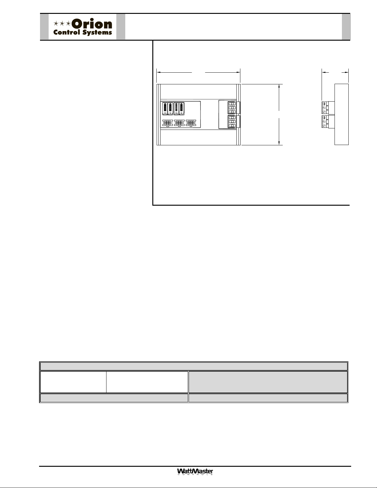
OE365-15-EBA-A - E-BUS Adapter Board
Description
The OE365-15-EBA-A E-BUS
Adapter Board is used to provide a
4.12
1.33
connection point for multiple EBUS Sensors or Modules.
The E-BUS Adapter Board is also
used for connecting an EBTRON
GTC-116 Airflow Measurement
Digital Transmitter or a Green-
TM
Trol
GA-200-N Transmitter Mod-
P2P1
J2 J3
MODULAR
EBUS
YS102478
REV 0
MADE IN USA
®
J1
MSTP EBUS
R+
SH
T-
R+
SH
T-
3.00
ule with GF Series Airflow Monitoring Station to the VCM-X
E-BUS Modular Controller*, RNE
Controller*, or VCB-X Controller.
You must wire the EBTRON
GreenTrol
TM
Airflow Measurement
Digital Transmitter to this Adapter
Board. Up to (3) EBTRON
GreenTrol
TM
Airflow Measurement
Digital Transmitters can be attached to the Adapter Board when using the VCM-X E-BUS Controller or
RNE Controller and up to (4) EBTRON
®
®
or
or
®
or GreenTrol
TM
Airflow Measurement Digital Transmitters can
be attached to the Adapter Board when using the VCB-X Controller.
The E-BUS Adapter Board has (3) HSSC Connections. One of these E-BUS ports is used to connect
the Board to the E-BUS Port on the VCM-X E-BUS Controller or RNE Controller using an HSSC EBUS cable.
The E-BUS Adapter Board also has (4) Modular E-BUS ports. One of these Modular E-BUS ports is
used to connect the Board to the E-BUS Port on the VCB-X Controller.
The EBUS Adapter Board also has (2) MSTP E-BUS Connections. The AirFlow Monitoring Station(s)
connect to one of the MSTP E-BUS Connections.
*NOTE: With custom VCM-X software, the Paragon MicroTrans EQ series Air Flow Monitoring Station
can be used and would wire into the E-BUS Adapter Board the same way.
Technical Data OE365-15-EBA-A E-BUS Adapter Board
Terminations (4) EBC Connections
(2) MSTP E-BUS Connections
(3) HSSC Connections
Three Year Warranty
EBTRON
GreenTrol
Paragon
®
is a registered trademark of Ebtron, Inc., Loris, SC.
TM
is a registered trademark of GreenTrol Automation, Inc. Loris, SC.
®
is a registered trademark of Paragon Controls, Inc. Santa Rosa, CA
.
WattMaster reserves the right to change specifications without notice
Form: ORION-OE365-15-EBA-A-E-BUS-Adapter-Board-1C.doc Page 1 of 1
Page 9
EBC-XXXF – EBC E-BUS Cables
3M
Description
4321
The EBC E-BUS Cables are used to
connect power and communications
between the VCB-X Controller, VCB-X
Expansion Module, E-BUS Modules,
and E-BUS Sensors.
The EBC E-BUS Cables are plenumrated high flex wire cables with an
EBC Connector on each end of the
F
XX
EBC-
cable.
The EBC E-BUS Cables are labeled
with “WATTMASTER E-BUS” marking
every foot.
Length
in Feet
The EBC E-BUS Cables are available
in 1, 1.5, 3, 10, 15, 25, 50, 75, 100,
150, and 250 foot lengths and
additionally a 1000 foot long spool.
"WATTMASTEREBUS" "WATTMASTEREBUS"
These lengths should satisfy most job
requirements. For length requirements
other than those listed, the MS000248
F
XX
EBC-
E-BUS Adapter Hub can be used to
connect EBC E-BUS Cables together
to provide for your specific-length
requirements.
The plug-in design of the EBC E-BUS
Cables eliminates costly wiring errors
and makes system installation easy.
The cable components are all UL
approved.
Technical Data EBC-XXXF EBC E-BUS Cables
EBC E-BUS Cable
Available Lengths and
Part Numbers
EBC-SPOOL-F (1000 Foot
Cable Type Plenum-rated High Flex Wire Wire Colors Red/Black First Pair; White/Blue Second
Wire Size 19 Strands of 32 Gage Wire, 4
Terminations Cable – 2 EBC Connectors Cable Sheath
Three Year Warranty
EBC-1-F (1 Foot)
EBC-1.5-F (1.5 Foot)
EBC-3-F (3 Foot)
EBC-25-F (25 Foot)
EBC-50-F (50 Foot)
EBC-75-F (75 Foot)
EBC-100-F (100 Foot)
EBC-150-F (150 Foot)
EBC-250-F (250 Foot)
Spool)
Conductor
Current Rating of
Cable Wire
UL Listing No. CMP/CL3P/FPLP
Color
WattMaster reserves the right to change specifications without notice
432 1
3M
CABLE SIDE
VIEW
EBC-XXF
E-BUS CABLE
300 Vrms Min = 10.15 Ohms per 1000
feet @ 20 Deg Celsius, Nominal
White, Plenum Rated CL3P/CMP
with “WATTMASTER EBUS”
marking every foot.
Pair
Form: ORION-EBC-XXXF-E-BUS-Cable-1B.doc Page 1 of 1
Page 10
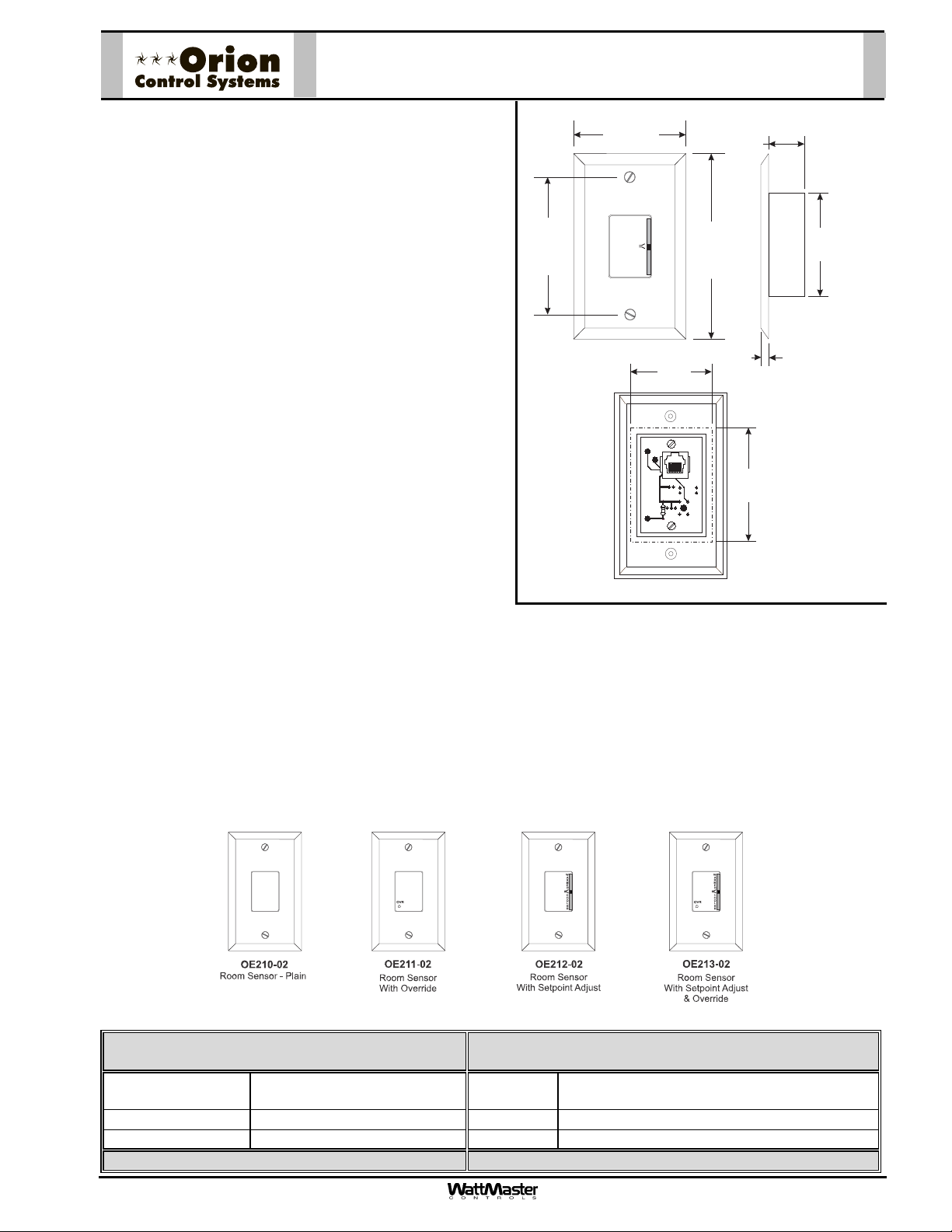
Description
The patented design, OE21x-02 series Modular Room
OE210-02, 211-02, 212-02, 213-02
Modular Room Sensors
2.75“
0.88“
Sensor provides accurate sensing of the room temperature. Its design allows for flush wall mounting yet rejects
the influence of surface and internal wall temperatures.
The Modular Room Sensor is used in conjunction with the
Orion VAV/Zone Controller. Connection between the
VAV/Zone Controller board and the Modular Room Sensor is by means of an RJ-45 Modular Cable. The Modular
3.25“
W
A
R
M
E
R
C
O
O
L
E
R
4.50“
2.50"
Room Sensor cannot be used for connection to the VCMX controller. For these applications the Standard Room
Sensor must be used. Please see the Orion Standard
Room Sensor submittal sheet for information.
Sensors provided with the setpoint adjustment option can
2.00“
0.25“
be programmed to allow a temperature range adjustment
of ± 6°
with the pushbutton override option can be programmed
to provide a timed override duration of up to 8.0 hours.
The Room Sensor’s attractive styling and off white casing
color make it suitable for most building decors. If interior
F from their standard setpoint. Sensors provided
YS101858
REV 0
MODULAR
SENSOR
Wall Cut-Out Dimensions
PJ1
R2
THERM1
R1
When Sensor Is To Be
Mounted Without
2.75“
Handy Box (By Others)
decoration requires, the Modular Room Sensor casing
can also be painted or wall papered without affecting the
sensor's performance. Modular Room Sensors are available in 4 different configurations:
OE210-02 - Sensor Plain
OE211-02 - Sensor with Override
OE212-02 - Sensor with Setpoint Adjustment
OE213-02 - Sensor with Setpoint Adjustment and Override
Modular cable from the VAV/Zone Controller to the Modular Room Sensor should not be run in conduit with other
AC line voltage wiring, or with any conductors carrying highly inductive loads.
Mounting
The Room Sensors are designed to be mounted on a vertical, 2” x 4” electrical box recessed in the wall. If the
wall cannot be penetrated, a plastic surface mount box such as those made by Wiremold, may be used to
mount the sensor to the wall surface.
Technical Data OE210-02, OE211-02, OE212-02, OE213-02
Modular Room Sensor
Sensor Element Type III Thermistor
10k ohm @ 77º F
Accuracy
0.4º F between 40º F to 95º F
Range -30º F to 150º F Weight 4 oz.
3 Year Warranty WattMaster reserves the right to change specifications without notice
Form: ORION-ModularRoomSensor-1F.doc Page 1 of 1
Mounting Designed to be Flush Mounted to Wall
using Vertical 2” x 4” Handy Box (by others)
Connection RJ-45 Modular Female Jack
Page 11
Description
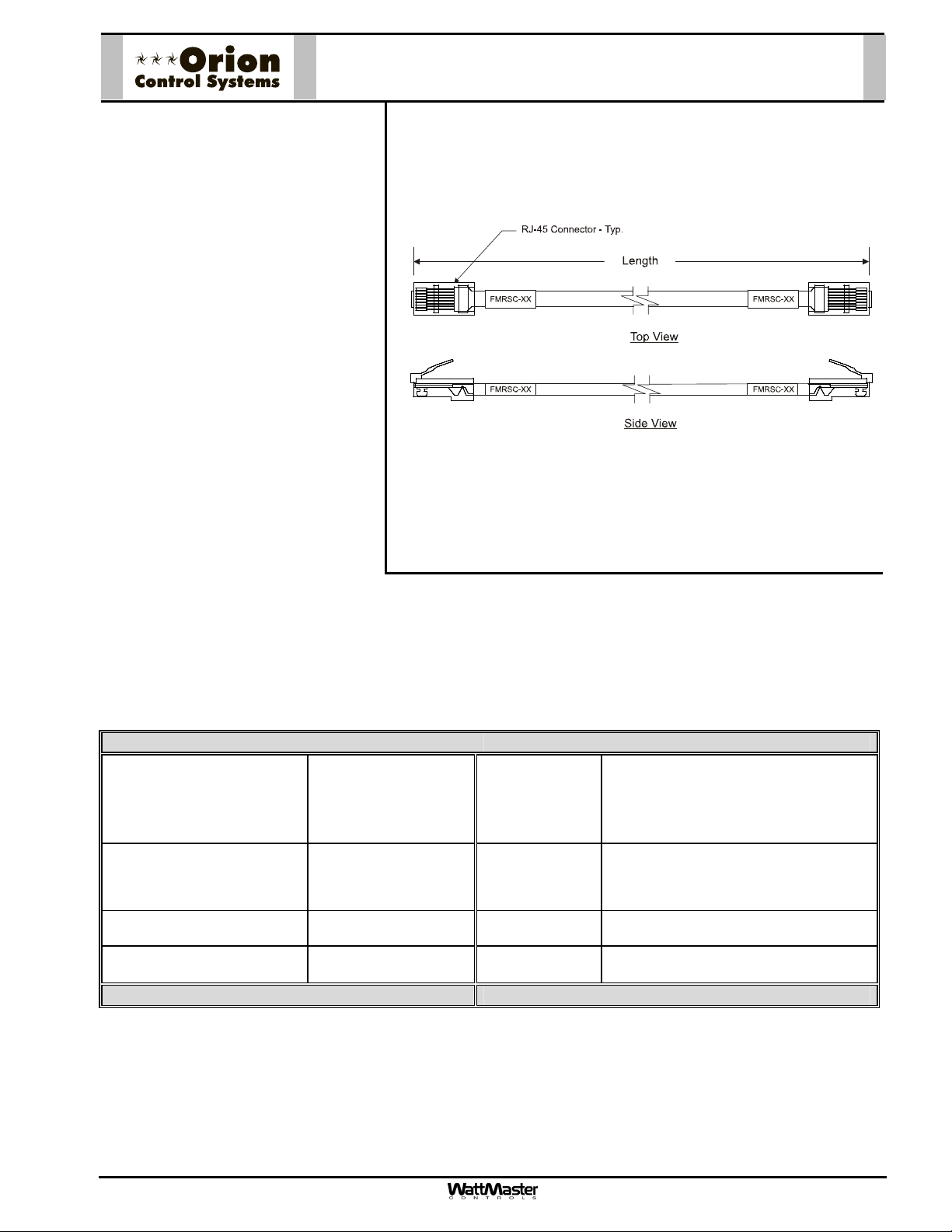
Modular Room Sensor Cable
FMRSC-XX
Description
The FMRSC Cables are used to
connect power and communications between the Modular Room
Sensor and the Orion VAV/Zone
Controller.
The FMRSC Cables are prefabricated plenum-rated cables with RJ45 Connectors on both ends of the
cable for connection between the
Modular Room Sensor and the
Orion VAV/Zone Controller.
The FMRSC Cables are labeled
near each end with the cable part
number.
The FMRSC Cables are available
in 5, 10, 25, 40 and 80 feet lengths.
These lengths should satisfy most
job requirements. For length requirements outside of this range, the MS000029 Modular Room Sensor
Cable Coupler can be used to connect two of the FMRSC Cables together to provide for your specificlength requirements. Not more than one coupler should be used on a run. Maximum run is 160 feet.
The plug-in design of the FMRSC Cables eliminates costly wiring errors and makes system installation
easy. The cable components are UL approved.
Technical Data FMRSC Modular Sensor Cables
FMRSC Cable Available
Lengths and Part Numbers
Cable Type Plenum-rated Wire Colors White W/ Green Stripe, Green W/ White
Wire Size 24 AWG Stranded
Terminations (2) RJ-45
Three Year Warranty
FMRSC-5 (5 Ft.)
FMRSC-10 (10 Ft.)
FMRSC-25 (25 Ft.)
FMRSC-40 (40 Ft.)
FMRSC-80 (80 Ft.)
6 Conductor
Connectors
Current Rating of
Cable Wire
Stripe, White W/ Orange Stripe, Orange
W/ White Stripe, White W/ Blue Stripe,
UL Listing No. CMP-UL As Per UL 910
Cable Sheath
Color
WattMaster reserves the right to change specifications without notice
24 AWG Wire = 0.577 Amps
(Maximum Amps
For Power Transmission)
Blue W/ White Stripe
Gray
Form: ORION-ModularCable-FMRSC-1B.doc Page 1 of 1
Page 12
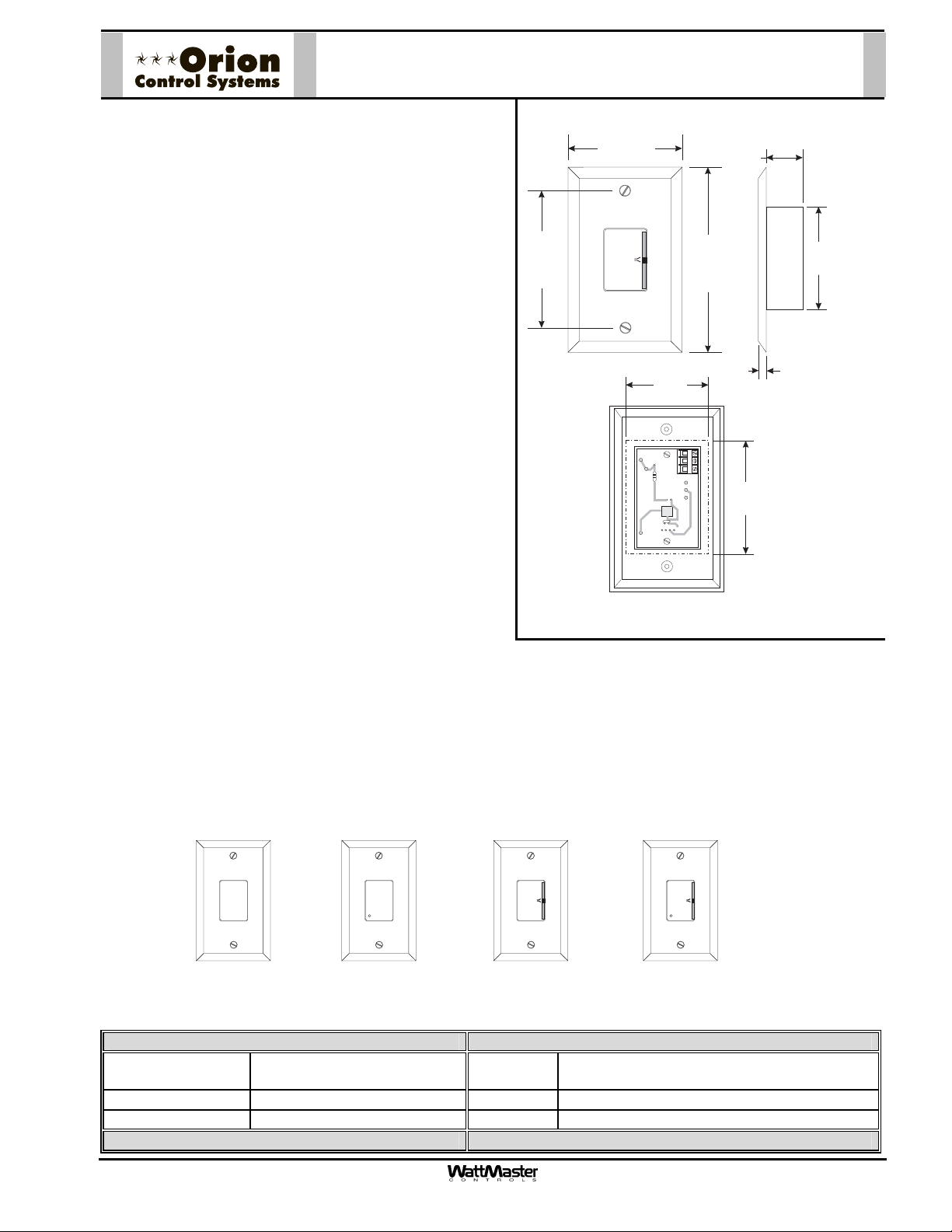
Description
The patented design, OE21x series Standard Room Sensor provides accurate sensing of the room temperature.
Its design allows for flush wall mounting yet rejects the
influence of surface and internal wall temperatures. The
Standard Room Sensor is used in conjunction with the
Orion controllers. Wire terminals are provided on the sensor for connection to the controllers. The Standard Room
Sensor cannot be used for connection to the VAV/Zone
controller. For this application the Modular Room Sensor
must be used. Please see the Orion Modular Room Sensor submittal sheet for information.
Sensors provided with the setpoint adjustment option can
be programmed to allow a temperature range adjustment
of ± 6°F from their standard setpoint. Sensors provided
with the pushbutton override option can be programmed
to provide a timed override duration of up to 8.0 hours.
The Room Sensor’s attractive styling and off white casing
color make it suitable for most building decors. If interior
decoration requires, the Room Sensor casing can also be
painted or wall papered without affecting the sensor's performance. Room Sensors are available in 4 different configurations:
OE210 Sensor Plain
OE211 Sensor with Override
OE212 Sensor with Setpoint Adjustment
OE213 Sensor with Setpoint Adjustment and
Override
OE210, 211, 212 & 213
Standard Room Sensors
2.00“
TMP
GND
AUX
OUT
4.50“
0.88“
0.25“
Wall Cut-Out Dimensions
When Sensor Is To Be
Mounted Without
2.75“
Handy Box (By Others)
2.50"
3.25“
2.75“
W
A
R
M
E
R
C
O
O
L
E
R
Mounting
The Room Sensors are designed to be mounted on a vertical, 2” x 4” electrical box recessed in the wall. If the
wall cannot be penetrated, a plastic surface mount box such as those made by Wiremold, may be used to
mount the sensor to the wall surface.
W W
A A
R R
M M
E E
R R
C C
O O
OVR OVR
OE210 OE211
Room Sensor - Plain
Room Sensor
With Override
With Setpoint Adjust
Technical Data OE210, OE211, OE212, OE213 Standard Room Sensor
Sensor Element Type III Thermistor
Mounting Designed to be Flush Mounted to Wall
10k ohm @ 77º F
Accuracy
0.4º F between 40º F to 95º F
Line Loss 0.25º F max. error, using 22 AWG wire at 1000 ft
Range -30º F to 150º F Weight 4 oz.
3 Year Warranty WattMaster reserves the right to change specifications without notice
O O
L L
E E
R R
OE212
Room Sensor
using Vertical 2” x 4” Handy Box (by others)
OE213
Room Sensor
With Setpoint Adjust
& Overide
Form: ORION-StandardRoomSensor-1D.doc Page 1 of 1
Page 13

OE230 (6" Probe) & OE231 (12" Probe)
Technical Specifications
Sensor Element:
Type III Thermistor 10k ohm @ 77ºF
Accuracy:
± 0.4º F between 40º F to 95º F
Range:
-30º F to 150º F
Caution!
The Duct Sensor Is Used For Sensing Supply
Or Return Air Temperatures. Location Of The
Sensors Is Very Important In Order To Obtain
Accurate Temperature Readings. The
Following Recommendations Should Be
Followed:
Supply Air
When Used As A Supply Air Sensor The
Sensor Should Be Mounted In The Supply Air
Duct As Close To The HVAC Unit As Possible
And Upstream Of The Bypass Damper (If
Used) For Best Results. For Best Accuracy,
Apply Insulation On The Outside Of The
Ductwork Over The Sensor. This Will Help
Thermal Gradients From Affecting The Sensor.
Return Air
When Used As A Return Air Sensor The
Sensor Should Be Mounted In The Return Air
Duct As Close To The HVAC Unit As Possible
And Upstream Of The Bypass Damper (If
Used) For Best Results. For Best Accuracy,
Apply Insulation On The Outside Of The
Ductwork Over The Sensor. This Will Help
Thermal Gradients From Affecting The Sensor.
See The Systems Installation And Operation
Manual For Other Design Considerations And
Recommendations Regarding Duct
Temperature Sensor Location.
Duct Temperature Sensors
Thread
Together
5-1/2" (OE230)
11-1/2" (OE231)
Leads Are Non-polarized.
Butt Splice Leads To 24 Gauge
Wire Minimum. Connect Leads
To "Analog In" And "Ground"
At Controller.
4.0"
3/4"
Mounting Plate
1/4" Hex Head Sheet Metal Screws
Mounting Plate
Gasket
Adhesive Backed Drill Guide
Mounting Template
Duct Work
Drill 3/8” Hole In Ductwork For Probe
Temperature Sensor Resistance/Voltage Chart
Temp Resistance* Voltage
°
F Ohms @ Input*
-10.............93333 ........4.620
-5...............80531 ........4.550
0 ...............69822........4.474
5 ...............60552........4.390
10..............52500........4.297
15..............45902........4.200
20..............40147........4.095
25..............35165........3.982
30..............30805........3.862
35..............27140........3.737
40..............23874........3.605
*Chart Notes:
1. Use the resistance column to check the thermistor sensor while disconnected from the controllers (not powered).
2. Use the voltage column to check sensors while connected to powered controllers. Read voltage with meter set on DC volts.
Place the "-"(minus) lead on GND terminal and the "+"(plus) lead on the sensor input terminal being investigated. If the voltage
is above 5.08 VDC, the sensor or wiring is "open." If the voltage is less than 0.05 VDC, the sensor or wiring is shorted.
Temp Resistance* Voltage
F Ohms @ Input*°
45..............21094........3.470
50..............18655........3.330
52..............17799........3.275
54..............16956........3.217
56..............16164........3.160
58..............15385........3.100
60..............14681........3.042
62..............14014........2.985
64..............13382........2.927
66..............12758........2.867
68..............12191........2.810
Temp Resistance* Voltage
F Ohms @ Input*°
69..............11906 ........2.780
70..............11652 ........2.752
71..............11379 ........2.722
72..............11136 ........2.695
73..............10878........2.665
74..............10625........2.635
75..............10398........2.607
76..............10158........2.570
78..............9711 ..........2.520
80..............9302..........2.465
82..............8893..........2.407
Temp Resistance* Voltage
°
F Ohms @ Input*
84..............8514..........2.352
86..............8153..........2.297
88..............7805..........2.242
90..............7472..........2.187
95..............6716..........2.055
100............6047..........1.927
105............5453..........1.805
110............4923..........1.687
115............4449..........1.575
120............4030..........1.469
125............3656..........1.369
Notes:
1.)All Wiring To Be In Accordance With
Local And National Electrical Codes
And Specifications.
FILENAME
G-DUCSENS1.CDR
DATE:
PAGE
1
07/13/15
DESCRIPTION:
OE230 & OE231
Duct Temperature Sensor
JOB NAME
DRAWN BY:
B. CREWS
Page 14

Gasketed Cover
Technical Specifications
Sensor Element:
Type III Thermistor 10k ohm @ 77ºF
Accuracy:
± 0.4º F between 40º F to 95º F
Range:
-30º F to 150º F
CAUTION!
See Note3
3.00”
Cover
Mounting
Screw - Typ.
2.30”
2.70”
Closure Plug
CAUTION!
See Note 2
0.21" Dia. x 0.73
Lg. Slot - Typ.
4.50”
3.00”
2.25”
1.13”
Sensor Tube
CAUTION!
See Note 1
Front View Side View
Outside Air Sensor OE250
Mounting Tab
& Screw - Typ.
Closure Plug
CAUTION!
See Note 2
Back View
Mounting Tab
& Screws - Typ.
Incorrect
See Note #1
Incorrect
Sensor Mounting
Postion
Correct
Temperature Sensor Resistance/Voltage Chart
Temp Resistance* Voltage
°
F Ohms @ Input*
-10.............93333 ........4.620
-5...............80531 ........4.550
0 ...............69822........4.474
5 ...............60552........4.390
10..............52500........4.297
15..............45902........4.200
20..............40147........4.095
25..............35165........3.982
30..............30805........3.862
35..............27140........3.737
40..............23874........3.605
Temp Resistance* Voltage
F Ohms @ Input*°
45..............21094........3.470
50..............18655........3.330
52..............17799........3.275
54..............16956........3.217
56..............16164........3.160
58..............15385........3.100
60..............14681........3.042
62..............14014........2.985
64..............13382........2.927
66..............12758........2.867
68..............12191........2.810
Temp Resistance* Voltage
F Ohms @ Input*°
69..............11906 ........2.780
70..............11652 ........2.752
71..............11379 ........2.722
72..............11136 ........2.695
73..............10878........2.665
74..............10625........2.635
75..............10398........2.607
76..............10158........2.570
78..............9711 ..........2.520
80..............9302..........2.465
82..............8893..........2.407
*Chart Notes:
1. Use the resistance column to check the thermistor sensor while disconnected from the controllers (not powered).
2. Use the voltage column to check sensors while connected to powered controllers. Read voltage with meter set on DC
volts. Place the "-"(minus) lead on GND terminal and the "+"(plus) lead on the sensor input terminal being investigated. If
the voltage is above 5.08 VDC, then the sensor or wiring is "open." If the voltage is less than 0.05 VDC, the sensor or
wiring is shorted.
Notes:
1.)The Outside Air Sensor Must Be
Mounted In A Vertical Position As
Shown (Sensor Tube Pointing
Water Must Not Be
Down).
Allowed To Stand In Sensor
Tube. Rainwater Will Damage
Sensor.
Sensor Must Be Located
Where It Will Not Be Affected By
Direct Sunlight Or Heat Producing
Equipment. If Possible Mount Under
Roof Eave Or Similar Protected
Location. If Sensor Is Not Located
As Specified, Erroneous Outside Air
2.)Unused Conduit Opening(s) Must
Have Closure Plugs Installed And Must
Be Coated with Sealing Compound To
Provide Raintight Seal. Water Can
Damage Sensor!
3.)Gasket Must Be Installed Under Cover
Plate To Provide Raintight Seal.
Rainwater Can Damage Sensor!
4.)All Wiring To Be In Accordance With
Local And National Electrical Codes
And Specifications.
Temperature Readings Will Result.
Temp Resistance* Voltage
°
F Ohms @ Input*
84..............8514..........2.352
86..............8153..........2.297
88..............7805..........2.242
90..............7472..........2.187
95..............6716..........2.055
100............6047..........1.927
105............5453..........1.805
110............4923..........1.687
115............4449..........1.575
120............4030..........1.469
FILENAME
G-OE250-OAS-PDWG.CDR
DATE:
PAGE
1
07/13/15
Outside Air Temperature Sensor
JOB NAME
DRAWN BY:
DESCRIPTION:
OE250
B. CREWS
Page 15

R
US CO
–
OE265-15-A
Description
The OE265-15-A E-BUS
Horizontal Outdoor Air
Temperature and Humidity is a
combination Outdoor Air
Temperature and Outdoor Air
Humidity sensor that connects to
the VCB-X Controller using an
EBC E-BUS modular cable.
This sensor is used when both
Outdoor Air Temperature and
Humidity are needed for the
VCB-X Controller to do Wetbulb
or Dewpoint Economizer Control.
It is also used if the VCB-X
Controller is used in a Make Up
Air application to initiate
dehumidification based on an
Outdoor Air Dewpoint Setpoint.
E-BUS Horizontal Outdoor
Air Temperature and Humidity Sensor
4.91
4.18
2.82
2.34
2.35
HINGED COVER
E-BUS CONNECTOR
FEMALE END
4321
3M
3.29
SENSING TUBE
36.00 APPROX.
FILTE
3M
4321
EBC-10F
"WATTMASTER EBUS" "WATTMASTER EBUS"
EBC-10F
3M
4321
120.00 APPROX.
E-B
NNECTOR EXTENSION CABLE WITH MALE ENDS PROVIDED WITH SENSOR
Mounting
A 10 foot EBC E-BUS cable (provided) plugs into the E-BUS Outdoor Air Temperature and Humidity Sensor's
attached 3 foot cable and then attaches to an E-BUS Expansion port on the VCB-X Controller or into another
available E-BUS Expansion port. The sensor should be mounted in the upright position as shown in an area that
is protected from the elements and direct sunlight.
CAUTION: Be sure to mount the E-BUS Outdoor Air Temperature & Humidity Sensor in an area that is not
exposed to direct sunlight. The shaded area under the HVAC unit rain hood is normally a good location. Unused
conduit opening(s) must have closure plugs installed and must be coated with sealing compound to provide a
rain-tight seal. Water can damage the sensor.
Technical Data OE265-15-A E-BUS Horizontal Outdoor Air Temperature
and Humidity Sensor
Sensor Element Digital Capacitive Sensing
Device
Sensor Reading
Range
Ambient Tempera-
40F to 120F
RH = 0-100%
-40F to 180F
ture Limits
Three Year Warranty
Accuracy
RH +/-2%, Temp +/- .5F
Connection
Weight
WattMaster reserves the right to change specifications without notice
E-BUS
2.3 oz.
Form: Orion-OE265-15-A-EBUS-Horiz-OA-RH-Sensor-01A Page 1 of 1
Page 16

.
US CO
–
Description
The OE265-16 E-BUS Vertical
Outdoor Air Temperature and
Humidity is a combination
Outdoor Air Temperature and
Outdoor Air Humidity sensor that
connects to the VCB-X Controller
using an EBC E-BUS modular
cable.
This sensor is used when both
Outdoor Air Temperature and
Humidity are needed for the
VCB-X Controller to do Wetbulb
or Dewpoint Economizer Control.
It is also used if the VCB-X
Controller is used in a Make Up
Air application to initiate
dehumidification based on an
Outdoor Air Dewpoint Setpoint.
OE265-16
E-BUS Vertical Outdoor
Air Temperature and Humidity Sensor
FILTER
4.91
4.18
2.82
2.34
SENSING TUBE
2.35
HINGED COVER
3.29
Mounting
A 10 foot EBC E-BUS cable
(provided) plugs into the E-BUS
Outdoor Air Temperature and
E-BUS CONNECTOR
FEMALE END
Humidity Sensor's attached 3
foot cable and then attaches to
4321
an
3M
E-BUS Expansion port on the
VCB-X Controller or into another
available E-BUS Expansion port.
The sensor should be mounted in
the upright position as shown in
an area that is protected from the
3M
4321
EBC-10F
"WATTMASTER EBUS" "WATTMASTER EBUS"
EBC-10F
elements and direct sunlight.
CAUTION: Be sure to mount the
E-BUS Outdoor Air Temperature
E-B
NNECTOR EXTENSION CABLE WITH MALE ENDS PROVIDED WITH SENSOR
120.00 APPROX.
& Humidity Sensor in an area that is not exposed to direct sunlight. The shaded area under the HVAC unit rain
hood is normally a good location. Unused conduit opening(s) must have closure plugs installed and must be
coated with sealing compound to provide a rain-tight seal. Water can damage the sensor.
Technical Data OE265-16 E-BUS Vertical Outdoor Air Temperature
and Humidity Sensor
Sensor Element Digital Capacitive Sensing
Device
Sensor Reading
Range
Ambient Temperature Limits
40F to 120F
RH = 0-100%
-40F to 180F
Three Year Warranty
Accuracy
Connection
Weight
WattMaster reserves the right to change specifications without notice
RH +/-2%, Temp +/- .5F
Form: Orion-OE265-16-EBUS-Vert-OA-RH-Sensor-01B Page 1 of 1
36.00 APPROX
3M
4321
E-BUS
2.3 oz.
Page 17

R
US CO
OE265-17-A
–
E-BUS Return Air
Description
The OE265-17-A E-BUS Return
Air Temperature and Humidity is
a combination Return Air
Temperature and Return Air
Humidity sensor that connects to
the VCB-X Controller using an
EBC E-BUS modular cable.
This sensor is used when both
Return Air Temperature and
Return Air Humidity are needed
for the VCB-X Controller. The
Return Air Humidity Sensor can
be used to initiate
dehumidification based on an
Indoor Humidity Setpoint.
Mounting
A 50 foot EBC E-BUS cable
(provided) plugs into the E-BUS
Return Air Temperature and
Humidity Sensor's attached 3
foot cable and then attaches to
an E-BUS Expansion port on the
VCB-X Controller or into another
available E-BUS Expansion port.
Temperature and Humidity Sensor
4.91
4.18
E-B
2.82
2.34
HINGED COVER
E-BUS CONNECTOR
FEMALE END
4321
3M
3M
4321
NNECTOR EXTENSION CABLE WITH MALE ENDS PROVIDED WITH SENSOR
"WATTMASTER EBUS" "WATTMASTER EBUS"
EBC-10F
50.00 FEET APPROX.
2.35
EBC-10F
3.29
36.00 APPROX.
3M
4321
ALL DIMENSIONS ARE
IN INCHES UNLESS
OTHERWISE NOTED.
FILTE
SENSING TUBE
Technical Data OE265-17-A E-BUS Return Air Temperature
and Humidity Sensor
Sensor Element Digital Capacitive Sensing
Device
Sensor Reading
Range
Ambient
40F to 120F
RH = 0-100%
-40F to 180F
Temperature
Limits
Three Year Warranty
Form: ORION-OE265-17-A-EBUS-Return-RH-Sensor-01A Page 1 of 1
Accuracy
RH +/-2%, Temp +/- .5F
Connection
Weight
WattMaster reserves the right to change specifications without notice
E-BUS
2.3 oz.
Page 18

T op
V iew
Left
Side
V iew
Front
V iew
Installation Instructions:
1.) Place The Outside Air Humidity Sensor Where It Is To Be Mounted. See Note 1 Below For
Important Mounting Information And Considerations. Mark The (4) Mounting Holes. Secure The
Humidity Sensor By Using The Four #10 X 1.5" Self Tapping Screws Included With The Humidity
Sensor.
Right
Side
V iew
6.70
INCORRECT
2.) Open The Cover by Moving the Latch to the Side And Install Your Conduit Connectors. The
Cover Must Always Be Opened Before Attempting To Punch Out The Knockouts.
3.) Connect The Wires To The Corresponding Sensor Wire Leads Per The Wiring Diagram On
Page 2 Of This Drawing. Insert the Wires Into the Sealant Filled Connectors Provided and Crimp.
Lightly Tug on the Wire to Assure a Good Mechanical Connection
4.) Close The Cover by Pushing Down Until the Latch Snaps Into Place. Be Careful Not To Pinch
The Sensor Wires When Closing The Housing Cover.
5.) Verify That You Are Getting A Humidity Reading On Your Control System. Please Note That It
May Take Ten To Twenty Minutes For The Sensor Reading To Stabilize Upon Initial Power Up.
Notes:
1.) The Outside Air Humidity Sensor Must
Be Mounted In A Vertical Position As Shown
(Sensor Tube Pointing Down). Water Must
Not Be Allowed To Stand In Sensor Tube,
it Will Cause Erroneous Sensor
Readings. The Sensor will recover when
it dries out. Sensor Must Be Located
Where It Will Not Be Affected By Direct
Sunlight Or Heat Producing Equipment. If
Possible Mount Under Roof Eave Or Similar
Protected Location. If Sensor Is Not
Located As Specified, Erroneous Outside Air
Humidity Readings Will Result.
2.) Unused Conduit Opening(s) Must
Not be Knocked Out to Prevent Dust
or Insects From Infiltrating the Sensor
Electrical Box.
3.) All Wiring To Be In Accordance
With Local And National Electrical
Codes And Specifications.
G-OE265-13B-OAHUMID-1F.PDF
PAGE
1 of 2
CORRECT
FILE NAME
DATE: 08/25/11
Outside Air Humidity Sensor – 0-5 VDC
INCORRECT
Sensor Mounting Position
JOB NAME
DRAWN BY: B. CREWS
DESCRIPTION
OE265-13 BAPI
Page 19

0-5 VDC Output Wiring (24VAC Power)
CONNECT TO
24 VAC POWER
Be Sure To Observe
Polarity Or Serious
Damage To The
Board Could Result
Terminal
0-5VDC
LB101966
Label:
Not Used
BLK
RED
GND
WHT
0-5V
VACorDC
SENSOR TERMINAL
BLOCK
Warning
Humidity Sensor
RH/Voltage Chart
RH Output
% VDC
5 .......... 0.25
10 .......... 0.50
15 .......... 0.75
20 .......... 1.00
25 .......... 1.25
30 .......... 1.50
35 .......... 1.75
40 .......... 2.00
45 .......... 2.25
50 .......... 2.50
*Chart Notes:
1. First, be sure that +24VAC power is being supplied to the sensor. Second check the
sensor output. Set the meter to DC volts and connect the meter between ground
and the 0-5 VDC input terminal on the controller board or between the 0-5 VDC
output on the sensor and its ground wire or you can measure voltage at the 0-5 VDC
and GND terminals on the sensor located at the sensor installtion location.
After measuring the voltage use an accurate humidity measurement device to
determine RH (relative humidity) such as an aspirating psychrometer. Use the
Output VDC column to read the Output Voltage corresponding with the RH
percentage measured with the psychrometer. If the measured voltage is within 3%
of what is listed for the corresponding RH, then the sensor is functioning properly.
Notes:
1.) All Wiring To Be In Accordance With Local And
National Electrical Codes And Specifications.
RH Output
% VDC
55 ........ 2.75
60 ........ 3.00
65 ........ 3.25
70 ........ 3.50
75 ........ 3.75
80 ........ 4.00
85 ........ 4.25
90 ........ 4.50
95 ........ 4.75
100 ........ 5.00
FILE NAME
G-OE265-13B-OAHUMID-1F.PDF
DATE: 08/25/11
PAGE
2 of 2
Outside Air Humidity Sensor – 0-5 VDC
JOB NAME
DRAWN BY: B. CREWS
DESCRIPTION
OE265-13 BAPI
Page 20

See Note #1
Mounting
Sensor to Duct
Top
View
Left
Side
View
Installation Instructions:
1.) Drill a 1" Diameter Hole In The Duct Wall In the Location Where The Humidity Sensor Is To Be Mounted. Insert The Probe Of The Return Air Humidity
Sensor Through The Hole. See Note 1 Below For Important Mounting Information And Considerations. Mark The (4) Mounting Holes. Secure The
Humidity Sensor By Using The Four #10 X 1.5" Self Tapping Screws Included With The Humidity Sensor.
2.) Open The Cover by Moving the Latch to the Side And Install Your Conduit Connectors. The Cover Must Always Be Opened Before Attempting To
Punch Out The Knockouts.
3.) Connect The Wires To The Corresponding Sensor Wire Leads Per The Wiring Diagram On Page 2 Of This Drawing. Insert the Wires Into the Sealant
Filled Connectors Provided and Crimp. Lightly Tug on the Wire to Assure a Good Mechanical Connection
4.) Close The Cover by Pushing Down Until the Latch Snaps Into Place. Be Careful Not To Pinch The Sensor Wires When
5.) Verify That You Are Getting A Humidity Reading On Your Control System. Please Note That It May Take Ten To Twenty Minutes For The Sensor
Reading To Stabilize Upon Initial Power Up.
Front View
Closing Th e Housing Cover.
Right
Side
View
Notes:
1.) The Sensor Should Be Mounted so
that the 6" Probe is in the Center of the
Return Air Duct. It Should be Mounted
Away from Fans, Elbows, Heating or
Cooling Coils or Other Equipment that
Could Affect the Measurement of
Relative Humidity. Also, the Sensor
Should be Mounted in an Area that
Receives Adequate Air Flow for Proper
Operation. The Sensor may be Mounted
Horizontally or Vertically to the Return Air
Duct. See the Sensor Mounting Diagram
Above.
2.) Unused Conduit Opening(s) Must Not
be Knocked Out to Prevent Dust or Insects
From Infiltrating the Sensor Electrical Box.
3.) The Sensor Probe Gasket Must Be
Installed Between the Back of the Sensor
Box and the Duct to Provide an Airtight
Seal.
4.) All Wiring To Be In Accordance With
Local And National Electrical Codes And
Specifications.
FILE NAME
G-OE265-14B-RAHUMID-1D.PDF
DATE: 08/28/07
PAGE
1 of 2
Return Air Humidity Sensor – 0-5 VDC
JOB NAME
DRAWN BY: B. CREWS
DESCRIPTION
OE265-14 BAPI
Page 21

0-5 VDC Output Wiring (24 VAC Power)
CONNECT TO
24 VAC POWER
Be Sure To Observe
Polarity Or Serious
Damage To The
Unit Could Result
Terminal
LB101966
0-5VDC
Label:
Not Used
BLK
RED
GND
WHT
0-5V
VACorDC
SENSOR TERMINAL
BLOCK
Warning
Humidity Sensor
RH/Voltage Chart
RH Output
% VDC
5 .......... 0.25
10 .......... 0.50
15 .......... 0.75
20 .......... 1.00
25 .......... 1.25
30 .......... 1.50
35 .......... 1.75
40 .......... 2.00
45 .......... 2.25
50 .......... 2.50
*Chart Notes:
1. First, be sure that +24VAC power is being supplied to the sensor. Second check the
sensor output. Set the meter to DC volts and connect the meter between ground
and the 0-5 VDC input terminal on the controller board or between the 0-5 VDC
output on the sensor and its ground wire or you can measure voltage at the 0-5 VDC
and GND terminals on the sensor located at the sensor installtion location.
After measuring the voltage use an accurate humidity measurement device to
determine RH (relative humidity) such as an aspirating psychrometer. Use the
Output VDC column to read the Output Voltage corresponding with the RH
percentage measured with the psychrometer. If the measured voltage is within 3%
of what is listed for the corresponding RH, then the sensor is functioning properly.
Notes:
1.) All Wiring To Be In Accordance With Local And
National Electrical Codes And Specifications.
RH Output
% VDC
55 ........ 2.75
60 ........ 3.00
65 ........ 3.25
70 ........ 3.50
75 ........ 3.75
80 ........ 4.00
85 ........ 4.25
90 ........ 4.50
95 ........ 4.75
100 ........ 5.00
FILE NAME
G-OE265-14B-RAHUMID-1D.PDF
DATE: 08/28/07
PAGE
2 of 2
Return Air Humidity Sensor – 0-5 VDC
JOB NAME
DRAWN BY: B. CREWS
DESCRIPTION
OE265-14 BAPI
Page 22

Right Side View
Front View
Installation Instructions:
1.) Place The SpaceHumidity Sensor Where It Is To Be Mounted. See Note 1 Below For Important Mounting Information And Considerations.
2.) Remove The Humidity Sensor Cover By Screwing In The 2 Allen Screws That Secure It To The Base.
3.) Connect All Of The Wires From The Controller Board To The Corresponding Terminal Blocks Per The Wiring Diagram On Page 2 Of This Drawing.
4.) Secure The Cover Onto The Base Housing By Snapping The Cover Onto The Base And Backing Out The 2 Allen Screws.
5.) Verify That You Are Getting A Humidity Reading On Your Control System. Please Note That It May Take Ten To Twenty Minutes For The Sensor
Reading To Stabilize Upon Initial Power Up.
Notes:
1.) The sensor is designed to be wall
mounted in rooms where appearance is
important. It may be mounted directly on
dry wall or on any single gang electrical
outlet box with no adapters required.
Toggle bolts or other direct wall mount
screws can be used where conduit is not
required. It includes a detachable
mounting plate. The cover is secured with
tamper-resistant hex screws. The sensor
should be mounted approximately five feet
above the floor, on an interior wall, away
from any heating or cooling generating
devices, and out of the sun. Plug the
wireway hole to prevent false readings by
air drafts within the wall.
2.) All Wiring To Be In
Accordance With Local
And National Electrical
Codes And Specifications.
FILE NAME
G-OE265-11-SPHUMID1D.PDF
DATE: 08/02/07
PAGE
1 of 2
Space Humidity Sensor – 0-5 VDC
JOB NAME
DRAWN BY: B. CREWS
DESCRIPTION
OE265-11
Page 23

0-5 VDC Output Wiring (24 VAC Power)
Be Sure To Observe
Polarity Or Serious
Damage To The
Board Could Result
Not Used
Not Used
0-5VDCTerminal
Gnd
Vin
Vo
Label: LB101969
Warning
Humidity Sensor
RH/Voltage Chart
RH Output
% VDC
5 .......... 0.25
10 .......... 0.50
15 .......... 0.75
20 .......... 1.00
25 .......... 1.25
30 .......... 1.50
35 .......... 1.75
40 .......... 2.00
45 .......... 2.25
50 .......... 2.50
*Chart Notes:
1. First, be sure that +24VAC power is being supplied to the sensor. Second, set the
meter to DC volts and connect the meter between ground and the 0-5 VDC input
terminal on the controller board or between the 0-5 VDC output terminal on the
sensor and its ground terminal. Use an accurate humidity measurement device to
determine RH (relative humidity) such as an aspirating psychrometer. Use the
Output VDC column to read the Output Voltage corresponding with the RH
percentage measured with the psychrometer. If the measured voltage is within 3%
of what is listed for the corresponding RH, then the sensor is functioning properly.
Notes:
1.) All Wiring To Be In Accordance With Local And
National Electrical Codes And Specifications.
RH Output
% VDC
55 ........ 2.75
60 ........ 3.00
65 ........ 3.25
70 ........ 3.50
75 ........ 3.75
80 ........ 4.00
85 ........ 4.25
90 ........ 4.50
95 ........ 4.75
100 ........ 5.00
FILE NAME
G-OE265-11-SPHUMID1D.PDF
DATE: 08/02/07
PAGE
2 of 2
Space Humidity Sensor – 0-5 VDC
JOB NAME
DRAWN BY: B. CREWS
DESCRIPTION
OE265-11
Page 24

Description
The OE265-06 Wall Mounted Humidistat
is used with the HVAC unit controller to
initiate dehumidification when the relative
humidity in the space rises above the
user adjustable setpoint. It is designed to
be mounted on the wall in the space
where sensing is required.
The Wall Mounted Humidistat is adjustable for relative humidity between 10%
to 90% with a differential relative humidity
of 5%.
OE265-06 – Wall Mounted
Humidistat
2.88"
% Relative Humidity
40 60 80
20
1.63”
The electrical switch on the Humidstat is
3.31”
4.38”
a snap-acting SPDT type. The switch is
rated at 8 Amps resistive load and 60 VA
pilot duty load at 24 VAC.
The Humidistat is enclosed in a beige
plastic housing with a removable cover.
The cover face is of brushed bronze with
relative humidity markings indicating
relative humidity setpoints between 10%
Mounting Holes
In Humidistat Base
to 90%. A removable dial is provided for
the adjustment of the relative humidity
setpoint. The Humidistat is also provided
with a blank cover plate to facilitate tamper proof installations. The external setpoint cover plate is first removed and
then the blank cover plate is installed. An
Allen screw and 5/64” Allen wrench is
also provided to complete the tamper proof hardware..
Six inch long color coded leads are provided on the back of the Humidistat base for wiring connections. A green
grounding lead is provided for grounding requirements.
Mounting
The Humidistat can be mounted to a flush or surface switch box using the provided screws. It can also be
mounted directly to the wall if your wiring codes allow for mounting of 24 Volt devices without a switch box.
Mounting screws for direct wall mounting must be provided by others.
Technical Data
Humidity Sensing
Element
Control Dial Settings 10 to 90% RH Location NEMA 1 Indoor Locations Only
Differential 5% RH Housing Beige Plastic with Brushed Bronze Cover
Operating Humidity 5% to 95% RH Non-
Operating Temp
Three Year Warranty
Form: ORION-OE265-06-Humidistat-1C.doc Page 1 of 1
Nylon Ribbon Electrical Switch Snap acting SPDT Rated at 8 Amps
Connections 6” Long Color Coded Wire Leads with
condensing
40°F to 125°F
Weight 1 Lb.
WattMaster reserves the right to change specifications without notice
OE265-06 Wall Mounted Humidistat
Resistive Load. 60 VA Pilot Duty Load
Plate. Also includes Tamper Proof Cover
Plate and Tamper Resistant Hardware
Ground Wire
Page 25

Description
The OE265-07 Duct Mounted
Humidistat is used with the
HVAC unit controller to initiate
dehumidification mode when the
relative humidity in the return air
duct rises above the user adjustable setpoint. The Duct Mounted
Humidistat is designed to be
mounted on the side of the HVAC
unit return air duct.
The Duct Mounted Humidistat is
adjustable for relative humidity
setpoints between 15% to 95%.
The Duct Mounted Humidistat
has a relative humidity differential
of 5%.
The electrical switch on the Duct
Mounted Humidstat is of the
snap-acting SPDT type. The
switch is rated at 8 Amps resistive load and 345 VA pilot duty
load at 120 VAC.
4.75”
OE265-07 – Duct Mounted
Humidistat
6.50”
0
2
0
1
% HUMIDITY
50
0
4
0
3
6
0
7
0
8
0
9
0
2.24"
1.25"
2.81"
The Humidistat is enclosed in a metal housing with a removable cover and duct mounting plate. The mounting
base plate face is labeled with relative humidity markings indicating relative humidity setpoints between 15% to
95%. A dial knob is provided for the adjustment of the relative humidity setpoint. The dial knob can be locked at
the setpoint position by tightening the dial lock screw to facilitate tamper proof installations.
Color coded wiring terminals are provided for wiring connections to the humidistat. A green grounding lead is
provided for grounding requirements.
Mounting
The Duct Mounted Humidistat is designed to be mounted on the side of the HVAC unit return air duct. 4 screws
are provided for mounting the humidistat to the return air duct. A mounting template is also provided to help locate the mounting holes and the duct cut-out on the duct wall.
Technical Data
Humidity Sensing
Element
Control Dial Settings 15 to 95% RH Location NEMA 1 Indoor Locations Only
Differential 5% RH Housing Painted Metal
Operating Humidity 5% to 95% RH Non-
Operating Temp
Three Year Warranty
Nylon Ribbon Electrical Switch Snap acting SPDT Rated at 8 Amps
Connections Color Coded Wire Terminals with Ground
condensing
40°F to 125°F
Weight 1.5 Lb.
WattMaster reserves the right to change specifications without notice
OE265-07 Duct Mounted Humidistat
Resistive Load. 345 VA Pilot Duty Load
Terminal
Form: ORION-OE265-07-Humidistat-1B.doc Page 1 of 1
Page 26

GasketedCover
CAUTION!
SeeNote3
SensorWire
LeadsInside
WeatherProof
Enclosure
AmbientLight
SensorEye
ThreadedInto
WaterProof
Enclosure
3.00”
Cover
Mounting
Screw-Typ.
2.30”
FrontView SideView
AmbientLightSensor OE259
MountingTab
&Screw-Typ.
ClosurePlug
CAUTION!
SeeNote2
2.70”
0.21"Dia.x0.73
Lg.Slot-Typ.
MountingTab
&Screws-Typ.
ClosurePlug
CAUTION!
SeeNote2
BackView
TheAmbientLightSensorIsAPhotoSensitiveResistorHousedInAWaterProofEnclosure.
ItIsUsedInConjunctionWithTheOE310-21-LPLightingControllerToSenseThePresenceOrAbsence
OfAmbientLightForTheControlOfLightingCircuitsConnectedToTheController.TheSensor
HasAResistanceInExcessOf1MOhmsInDarknessAndRangesDownToLessThan1.5KOhmsIn
BrightLight.TheSensorWireConnectionsAreNon-Polarized.SeeTheOE310-21-LPWiringDiagramFor
CorrectWiringConnections.SeeNote1ForMountingLocationCautions.
Notes:
1.)TheAmbientLightSensorShould
BeInstalledOutdoorsWhereItCan
SenseTheAmbientLightLevel.Do
NotMountInAShadyAreaOrNear
AnyObstructionsThatWouldBlock
TheSensorEye.TheAmbientLight
SensorShouldBeMountedOnIts
SideInAHorizontalPositionSo
WaterWillNotPuddleAroundThe
SensorEye.
2.)UnusedConduitOpening(s)Must
HaveClosurePlugsInstalledAndMust
BeCoatedwithSealingCompoundTo
ProvideRaintightSeal.WaterCan
DamageSensor!
CorrectMountingPosition IncorrectMountingPosition
3.)GasketMustBeInstalledUnderCover
PlateToProvideRaintightSeal.
RainwaterCanDamageSensor!
4.)AllWiringToBeInAccordanceWith
LocalAndNationalElectricalCodes
AndSpecifications.
FILENAME
G-OE259-AmbLightSnsr1A.CDR
DATE: B.CREWS
PAGE
1
06/17/03
DESCRIPTION:
AmbientLightSensor
JOBNAME
DRAWNBY:
OE259
Page 27

Butt Splice Wire Leads To Extend Wires To
Controller Terminals. Connect One Wire
Lead To Return Water Temperature Or
Supply Water Temperature Terminal At The
Controller As Required By Intended Use.
Secure Other Wire Lead To Ground
Terminal At The Controller. See Note 3.
Secure Sensor Element And Thermal
Mastic Strip To Pipe With Supplied
Wire Tie. Be Sure To Tighten Wire Tie
Snugly To Ensure Good Thermal Contact
Between Pipe And Sensing Element.
Sensing Element
(Supplied)
Install Sensing
Element With
Curved Face
Touching Pipe
Surface As Shown
Wire Tie
(Supplied)
Supply Or Return
Water Pipe. See Note1&2.
Important Note:
For Accurate Temperature
Readings
It Is Necessary To Place
Insulation Over The Sensor
After Installation. This
Prevents The Ambient
Temperature From Affecting
The Sensor. Insulation Should
Cover The Sensor And Extend
6“ to 12” Beyond Each End Of
The Sensor.
Temp Resistance* Voltage
F Ohms @ Input*
°
-10.............93333 ........4.620
-5...............80531 ........4.550
0 ...............69822........4.474
5 ...............60552........4.390
10..............52500........4.297
15..............45902........4.200
20..............40147........4.095
25..............35165........3.982
30..............30805........3.862
35..............27140........3.737
40..............23874........3.605
*Chart Notes:
1. Use the resistance column to check the thermistor sensor while disconnected from the controllers (not powered).
2. Use the voltage column to check sensors while connected to powered controllers. Read voltage with meter set on DC volts.
Place the "-"(minus) lead on GND terminal and the "+"(plus) lead on the sensor input terminal being investigated. If the voltage
is above 5.08 VDC, the sensor or wiring is "open." If the voltage is less than 0.05 VDC, the sensor or wiring is shorted.
Notes:
1.)Sensor Should Be Mounted At
Location Along Pipe Length
That Best Represents Desired
Temperature Reading.
2.)Sensing Element Shown
Mounted To Top Of Pipe. The
Sensor Element May Be Located
At Any Location Around Pipe.
3.)All Wiring To Be In Accordance
With Local And National Electrical
Codes And Specifications.
Thermal Mastic
Place Between Pipe
And Sensing Element. Pipe Should Be
Clean And Smooth To Provide Proper
Thermal Contact With Sensing Element.
Thermal Mastic Strip
(Supplied)
Temperature Sensor Resistance/Voltage Chart
Temp Resistance* Voltage
F Ohms @ Input*°
45..............21094........3.470
50..............18655........3.330
52..............17799........3.275
54..............16956........3.217
56..............16164........3.160
58..............15385........3.100
60..............14681........3.042
62..............14014........2.985
64..............13382........2.927
66..............12758........2.867
68..............12191........2.810
Temp Resistance* Voltage
F Ohms @ Input*°
69..............11906 ........2.780
70..............11652 ........2.752
71..............11379 ........2.722
72..............11136 ........2.695
73..............10878........2.665
74..............10625........2.635
75..............10398........2.607
76..............10158........2.570
78..............9711 ..........2.520
80..............9302..........2.465
82..............8893..........2.407
FILENAME
G-OE233-W-TempSnsr1a.CDR
DATE: 01/03/05
PAGE
OE233 - Strap-On Temperature
1
Temp Resistance* Voltage
F Ohms @ Input*
°
84..............8514..........2.352
86..............8153..........2.297
88..............7805..........2.242
90..............7472..........2.187
95..............6716..........2.055
100............6047..........1.927
105............5453..........1.805
110............4923..........1.687
115............4449..........1.575
120............4030..........1.469
125............3656..........1.369
JOB NAME
CONTROLS
DRAWN BY:
DESCRIPTION:
B. CREWS
Sensor Kit Installation
Page 28

Static Pressure Pickup Tube OE290
Connect This End Of Tubing To “Hi”
Port Of Pressure Sensor
1/4“ O.D. X 3/16” I.D. x 14” Long - Fire Rated Tubing
Slide Over 1/4“ Barb Fitting
Tubing Not To Exceed 250 Ft. Length.
Do Not Splice Tubing.
1/8“ MPT
Threaded Pipe
Thread
Together
1/4“ Barb Fitting
3/4"
2-3/4“
1/4" Hex Head Sheet Metal Screws
Drill 5/16" Hole In Ductwork For Probe
Mounting Plate
Mounting Plate
Gasket
Adhesive Backed Drill Guide
Mounting Template
Duct Work
4.0"
Caution!
In Order To Obtain Accurate Static Pressure Readings
The Static pressure Pickup Probe Should Be Mounted
Per The Following Recommendations:
1.)The Probe Should Be Mounted In a Straight Section
Of Ductwork Approx. 2/3 The Length Of the Supply Duct,
Downstream Of The HVAC Unit.
2.)The Probe Should Not Be Mounted Less Than 3 Duct
Diameters Downstream Or Not Less Than 2 Duct
Diameters Upstream Of Any Elbow or Takeoff.
See The Systems Installation And Operation Manual For
Other Design Considerations And Recommendations
Regarding Static Pressure Pickup Tube Location.
Notes:
1.)The Static Probe(OE290) Is Supplied With A 14“
Length Of Tubing For Connection To The Static
Pressure Sensor. The Static Pressure Sensor
(OE271) Is Designed To Be Mounted Adjacent To The
Location Where The Static Pickup Tube Is Mounted
And Wired Back To The Controller Board. The Static
Pressure Sensor Can Also Be Mounted Close To The
Controller Board And Tubing (By Others) Routed
From The Sensor To The Static Pickup Probe. Be
Sure Not To Kink The Tubing Between The Static
Pickup Probe And The Static Pressure Sensor.
FILENAME
SPUTUBE1.CDR
DATE:
PAGE
1
05/21/00
Static Pressure Pickup Tube
JOB NAME
CONTROLS
DRAWN BY:
DESCRIPTION:
OE290
B. CREWS
Page 29

The OE230 Duct Sensor Threads Into
The OE291 Stainless Steel Thermowell.
The OE291 Thermowell Threads Into A
1/2” FPT Elbow or Tee in the Water Piping
of the Water Coil at Which You wish to
Measure the Water Temperature. The
Pipe must be a minimum of 4” Diameter
or an Extended Tee and Bushing
Configuration Must be Used to
Accommodate the Length of the
Thermowell Assembly.
Leads Are Non-polarized.
Butt Splice Leads To 24
Gauge Wire Minimum.
Connect Leads To
"Analog In" And "Ground"
At Controller.
OE230 Temperature Sensor
(Ordered Separately)
Caution!
The Duct Sensor Is Used For Sensing Entering Or
Leaving Water Temperatures. Location Of The
Sensors Is Very Important In Order To Obtain
Accurate Temperature Readings. The Following
Recommendations Should Be Followed:
Entering Water
When Used As A Supply Water Temperature
Sensor The Sensor Should Be Mounted In The
Supply Water Piping As Close To The Water Coil
As Possible For Best Accuracy, Apply Insulation
On The Outside Of The Piping Over The Sensor.
This Will Help Thermal Gradients From Affecting
The Sensor.
Leaving Water
When Used As A Leaving Water Temperature
Sensor The Sensor Should Be Mounted In The
Return Piping As Close To The Water Coil Outlet
As Possible. For Best Accuracy, Apply Insulation
On The Outside Of The Piping Over The Sensor.
This Will Help Thermal Gradients From Affecting
The Sensor.
See The Systems Installation And Operation
Manual For Other Design Considerations And
Recommendations Regarding Water Temperature
Using OE230 Temperature Sensor
1/8 -27 NPT External Thread"
1/8 -27 NPSM Internal Thread"
OE291 Stainless Steel Thermowell
5.13"
4.94
"
3.25"
1/2" NPT External Thread
0.5"
OE291 Thermowell Assembly
Temp Resistance* Voltage
F Ohms @ Input*
°
-10.............93333 ........4.620
-5...............80531 ........4.550
0 ...............69822........4.474
5 ...............60552........4.390
10..............52500........4.297
15..............45902........4.200
20..............40147........4.095
25..............35165........3.982
30..............30805........3.862
35..............27140........3.737
40..............23874........3.605
*Chart Notes:
1. Use the resistance column to check the thermistor sensor while disconnected from the controllers (not powered).
2. Use the voltage column to check sensors while connected to powered controllers. Read voltage with meter set on DC volts.
Place the "-"(minus) lead on GND terminal and the "+"(plus) lead on the sensor input terminal being investigated. If the voltage
is above 5.08 VDC, the sensor or wiring is "open." If the voltage is less than 0.05 VDC, the sensor or wiring is shorted.
Notes:
1.)All Wiring To Be In Accordance With
Local And National Electrical Codes
And Specifications.
Temperature Sensor Resistance/Voltage Chart
Temp Resistance* Voltage
F Ohms @ Input*°
45..............21094........3.470
50..............18655........3.330
52..............17799........3.275
54..............16956........3.217
56..............16164........3.160
58..............15385........3.100
60..............14681........3.042
62..............14014........2.985
64..............13382........2.927
66..............12758........2.867
68..............12191........2.810
Temp Resistance* Voltage
F Ohms @ Input*°
69..............11906 ........2.780
70..............11652 ........2.752
71..............11379 ........2.722
72..............11136 ........2.695
73..............10878........2.665
74..............10625........2.635
75..............10398........2.607
76..............10158........2.570
78..............9711 ..........2.520
80..............9302..........2.465
82..............8893..........2.407
FILENAME
G-OE291-T-Well.CDR
DATE:
PAGE
1
07/09/04
Water Temperature Sensor Thermowell
Temp Resistance* Voltage
F Ohms @ Input*
°
84..............8514..........2.352
86..............8153..........2.297
88..............7805..........2.242
90..............7472..........2.187
95..............6716..........2.055
100............6047..........1.927
105............5453..........1.805
110............4923..........1.687
115............4449..........1.575
120............4030..........1.469
125............3656..........1.369
JOB NAME
DRAWN BY:
DESCRIPTION:
B. CREWS
OE291
Page 30

OE271 - For
Applications
0-5” H O Pressure Range - 5 VDC Operation
2
Minimum Typical Maximum
Full Scale Output
(Positive Pressure)
Null Offset
Span*
Non-Linearity
Hystereisis And Repeatability
Temperature Error
Null +10 To 40 C°°
Span +10 To 40 C°°
Stability (1 Year)
Supply Voltage (Vs)
Common Mode Pressure
Pressure Overload
Positive Pressure (Hi Side)
Negative Pressure (Lo Side)
Burst Pressure
Positive Pressure (Hi Side)
Negative Pressure (Lo Side)
*Span Is The Algebraic Difference Between End Points (Null OffsetAnd Full Scale Output)
3.92 VDC
0.17 VDC 0.2-0.3 VDC 0.33 VDC
3.59 VDC 3.91 VDC
4.75 VDC 5.0 VDC
Requiring 0-5” H O Pressure Range
3.95-4.05 VDC
3.65-3.85 VDC
±0.3 % Span ±0.5 % Span
±0.03 % Span
±1.0 % Span
±1.0 % Span
±0.5 % Span
Airflow Sensor
2
4.08 VDC
±0.05 % Span
±1.5 % Span
±1.5 % Span
8.0 VDC
15 PSI
25“ H O
2
15“ H O
2
50“ H O
2
25“ H O
2
1.29"
2.94"
0.15"
2.50"
2.20"
IN (Red)
GND
OUT
IN
UP
OE271
S.P. Sensor
(-)LO
Top View
12.0" APPROX.
OUT (Black)
GND (Green)
0.15" DIA.
0.60"
0.200" (3/16" Tubing Conn.)
0.125" (1/8" Tubing Conn.)
Warning!
The plastic housing on the sensor is electrically
conductive. Avoid contact with any electrical components.
It is acceptable to mount the sensor on grounded sheet
metal such as ductwork, electrical panels, etc.
Warning!
Use extreme care when mounting the sensor to avoid
damage to the plastic housing. Do not overtighten the
mounting screws! Do not use mounting screws which are
too large for the holes!
General Notes
Caution:
1.) The Airflow Sensor Should Be Mounted In
A Vertical Position As Shown With Arrow Pointing
Up. ( Tubing Connections Pointing Down). If This
Mounting Position Is Not Possible In Your
Application, It May Be Mounted In A Horizontal
Position. When Mounted In A Horizontal Position
Accuracy Will Be Affected By Approximately 2% Full
Scale Null Shift Due To Diaphragm Gravity Effect
Error.
Duct Static Pressure Sensor Applications
Mounting Information
When The OE271 Is Used As A Duct
Pressure Sensor
Ductwork Near The Static Pressure Pickup Tube. If
The Sensor Is Mounted In This Manner, Away
From The Controller, The Modular Plug Must Be
Cut Off And 3-conductor 24 Gauge Minimum Wire
Must Be Butt Spliced Between The Sensor And
The Modular Plug To Extend The Sensor Wire
Length. Total Wire Length Should Not Exceed
100Ft. If Desired The Sensor May Also Be Located
Near The Controller, With The Modular Plug On
The Sensor Directly Connected To The Mating
Controller Jack. When This Method Is Used Tubing
Must Be Run From The Sensor To The Static
Pressure Pickup Tube. Tubing Should Not Exceed
250 Ft. And Must Be Continuous Without Any
Splices.
It May Be Mounted To The
0.35"
2.)All Wiring To Be In Accordance With Local And
National Electrical Codes And Specifications.
VAV Pressure Independent Airflow Sensor
Applications Mounting Information
Static
When The OE271 Is Used As An Airflow
For VAV Applications It Should Be Mounted In The
VAV Box Control Enclosure Near The Box
Controller Board. The Modular Plug should be
Connected To The VAV Controller Board
Connection. Tubing Must Be Run From The
Sensor to The Airflow Pickup Probe Tubing
Connection.
G-OE271TRAN1.CDR
DATE:
PAGE
1
FILENAME
08/19/08
1.95"
Side View
Sensor
JOB NAME
DRAWN BY:
DESCRIPTION:
OE271
Pressure Sensor
0.55"
1.00"
B. CREWS
Page 31

OE274 - Velocity Pressure For P. I. VAV/Zone ControlSensor
0-1.5“ H O Pressure Range - 5 VDC Operation
2
Minimum Typical Maximum
Full Scale Output
(Positive Pressure)
Null Offset
Span*
Non-Linearity
Hystereisis And Repeatability
3.92 VDC
3.95-4.05 VDC
0.17 VDC 0.2-0.3 VDC 0.33 VDC
3.59 VDC 3.91 VDC
3.65-3.85 VDC
±0.3 % Span ±0.5 % Span
±0.03 % Span
Temperature Error
Null +10 To 40 C°°
Span +10 To 40 C°°
Stability (1 Year)
Supply Voltage (Vs)
4.75 VDC 5.0 VDC
±1.0 % Span
±1.0 % Span
±0.5 % Span
Common Mode Pressure
Pressure Overload
Positive Pressure (Hi Side)
Negative Pressure (Lo Side)
Burst Pressure
Positive Pressure (Hi Side)
Negative Pressure (Lo Side)
*Span Is The Algebraic Difference Between End Points (Null Offset And Full Scale Output)
4.08 VDC
±0.05 % Span
±1.5 % Span
±1.5 % Span
±1 % Span
8.0 VDC
15 PSI
5“ H O
2
3“ H O
2
10“ H O
2
5“ H O
2
2.94"
1.29"
0.15"
2.50"
2.20"
IN (Red)
GND
OUT
IN
UP
OE274
P.I. Sensor
(-)LO
Top View
1.95"
12.0" APPROX.
OUT (Black)
GND (Green)
0.15" DIA.
0.60"
0.200" (3/16" Tubing Conn.)
0.125" (1/8" Tubing Conn.)
0.55"
Warning! Warning!
The plastic housing on the sensor is electrically
conductive. Avoid contact with any electrical components.
It is acceptable to mount the sensor on grounded sheet
metal such as ductwork, electrical panels, etc.
Notes:
1.) The Velocity Pressure Sensor Should Be
Caution:
Mounted In A Vertical Position As Shown With
Arrow Pointing Up. ( Tubing Connections Pointing
Down). If This Mounting Position Is Not Possible In
Your Application, It May Be Mounted In A Horizontal
Position. When Mounted In A Horizontal Position
Accuracy Will Be Affected By Approximately 2% Full
Scale Null Shift Due To Diaphragm Gravity Effect
Error.
2.)All Wiring To Be In Accordance With Local And
National Electrical Codes And Specifications.
0.35"
Side View
Use extreme care when mounting the sensor to avoid
damage to the plastic housing. Do not overtighten the
mounting screws! Do not use mounting screws which are
too large for the holes!
1.00"
FILENAME
PITRAN1.5.CDR
DATE:
PAGE
1
10/20/01
Pressure Independent Velocity Sensor
JOB NAME
CONTROLS
DRAWN BY:
DESCRIPTION:
OE274
B. THRALL
Page 32

Description
The OE258 Building Static Pressure Sensor is used to sense building pr essure in
applications where monitoring of the
building static pressure is required to insure the building maintains the proper air
pressurization.
0.95
0.156 DIA. HOLE
TYP. 2 PL.
MODEL 265
The OE258 Building Pressure Sensor
case is molded from fire retardant glass
filled polyester. The sensor utilizes a tensioned stainless steel diaphragm and insulated stainless steel electrode. This
arrangement allows up to 10 PSI overpressure without damage to the unit. T he
sensor provides a 0.0 to 5.0 VDC output
in response to a –0.25 to +0.25 inch WC
pressure differential. Ac curacy is ± 1% of
full scale of the sensor.
For easy wiring the OE258 Building Static
Pressure Sensor has (3) 6- 32 screw terminal wiring connectors. The sensor has
(2) ¼” barbed fittings provided for the
connection of tubing to the high and low
pressure ports.
The OE258 Static Pressure Sensor is
designed to be mounted to a flat surf ace
by means of the (2) 0.156 diam eter holes
provided in the sensor casing. For accurate readings the sensor must be
mounted in a vertical position.
2.74
HIGH
setra
LOW
-
0.95
+
1.89
3.16
+
+
1.64
Technical Data OE258 - Building Static
Pressure Sensor
Operating Pressure
Range
Operating Temp
Circuit 3 Wire Non-repeatability
Accuracy
Three Year Warranty WattMaster reserves the right to change specifications without notice
Form: ORION-OE258-6-BuildingPressureSensor-1B.doc
-0.25” WC to +0.25” WC
Pressure Differential
0°F to 150°F
± 1% of full scale
Power Input
Signal Output
Hysteresis
Weight 3 ounces
± 0.1% of full scale
± 0.05% of full scale
9-30 VDC
0 to 5 VDC
Page
1 of 1
Page 33

Description
The OE256-01 Wall Mounted CO2 Sensor is
used in conjunction with the VCM-X Controller (OE332-23-VCM) to monitor and control
levels in the building environment.
CO
2
Some typical applications are:
Demand Ventilation Control
Controlling ventilation in a building
where the occupancy varies frequently
Controlling ventilation based on CO
2
levels to ensure excess outside air is
not causing energy waste
To ensure good air distribution
throughout building zones
The OE256-01 is used for monitoring room
levels and is designed for permanent
CO
2
wall mounting in the conditioned space. It
connects to the VCM-X Controller by using a
modular prefabricated cable with RJ-45 connectors. It can be daisy chained with the Orion Modular Room Temperature Sensor or
Digital Room Temperature Sensor for applications requiring both a room CO
and room temperature sensor.
The OE256-01 CO
Sensor uses non-
2
dispersive infrared (NDIR) technology. The
CO
Sensor’s accuracy is 50 ppm @1000
2
ppm or 2% of the measured value and has a
measurement range of 0-2000 ppm.
sensor
2
OE256-01 Wall Mounted CO2 Sensor
Mounting
The OE256-01 CO2 Sensor utilizes a subbase mounting plate with either terminal blocks or modular phone jack providing for quick and easy mounting and
wiring. The wall-mounted sensor’s sub-base is compatible with standard junction boxes. A locking screw secures
the assembly to the wall.
Technical Data OE256-01 – CO
Input Power 12-34 VDC Power Consumption 30 mW Maximum Average
1.25 W Peak Power
Operating Temperature
Sample Method Diffusion Or Flow—through
Sensitivity
Analog Output 0-5 VDC Communications I2C
One Year Warranty WattMaster reserves the right to change specifications without notice
14 to 122 F
50-100 ml/min
<20 ppm
Operating Humidity 5-95% RH Non-Condensing
Measurement Range 0 to 2000 ppm
Resolution
Form: ORION-OE256-01-CO2Sensor-1C.doc Page 1 of 1
Sensor
2
1 ppm
Page 34

Description
The OE256-02 Duct Mounted CO2 Sensor
is used in conjunction with the VCM-X Controller (OE332-23-VCMX) to monitor and
control CO
ment. It can be configured via its address
switch to be either a Supply Air CO
sor or Return Air CO
Some typical applications are:
levels in the building environ-
2
Sen-
Sensor as required.
2
2
• Demand Control Ventilation
• Controlling ventilation in a building
where the occupancy varies frequently
• Controlling ventilation based on CO
levels to ensure excess outdoor air is
not causing energy waste
2
• To ensure good air distribution
throughout building zones
The OE256-02 is used for monitoring duct
CO
levels and is designed for permanent
2
duct mounting in the Supply or Return Air
duct. It utilizes an aspiration box to accurately capture CO
Return Air duct. It connects to the VCM-X
by using a modular prefabricated cable with
RJ-45 connectors. It can be daisy chained
with the Orion Modular Room Temperature
Sensor or Digital Room Temperature Sensor for applications requiring both a room
CO
sensor and room temperature sensor.
2
The OE256-02 CO2 Sensor uses nondispersive infrared (NDIR) technology and
has a measurement range of 0-2000 ppm.
levels in the Supply or
2
OE256-02 Duct Mounted CO2 Sensor
Mounting
The OE256-02 CO2 Sensor is housed in an
aspiration box. The sensor has an integral
mounting sub-base mounting plate with
modular phone jacks for connecting it to
the VCM-X and another Digital or Modular
Room Temperature Sensor. A conduit
clamp is provided to help seal the opening where the sensor cabling penetrates the aspiration box housing. The sensor and
aspiration box assembly is mounted to the ductwork by first cutting a 1
piration tube. The aspiration tube is then inserted into the hole. The aspiration box sensor assembly is then secured to the
ductwork by inserting (4) supplied sheet metal screws through (4) mounting holes in the aspiration box base and securing the
assembly by screwing it to the ductwork using a manual or powered screw driver to tighten the screws.
Technical Data OE256-02 Duct Mounted CO
Input Power 12-34 VDC Power Consumption 30 mW Maximum Average
Operating Temperature
Sample Method Flow-Through
Sensitivity
Accuracy
One Year Warranty WattMaster reserves the right to change specifications without notice
Form: ORION-OE256-02-DuctMtdCO2Sensor-1A.doc Page 1 of 1
±50 ppm @ 1000 ppm or 2%
14° to 122° F
50-100 ml/min
<±20 ppm
measured value
Operating Humidity 5-95% RH Non-Condensing
Measurement Range 0 to 2000 ppm
Resolution
Communications I
1
/4” diameter hole in the duct wall for insertion of the as-
Sensor
2
1.25 W Peak Power
±1 ppm
2
C
Page 35

OE256-05 Wall Mounted E-BUS CO2 Sensor
Description
The Wall Mounted E-BUS CO2 Sensor (Orion Part No.
OE256-05; AAON Part No. V09310) is used in conjunction with the VCB-X Controller (Orion Part No.
OE335-23-VCB-X; AAON Part No. V04740) to monitor
and control CO
levels in the building environment.
2
Some typical applications are:
Demand Ventilation Control
Controlling ventilation in a building where the oc-
cupancy varies frequently
Controlling ventilation based on CO
levels to
2
ensure excess outside air is not causing energy
waste
To ensure good air distribution throughout build-
ing zones
The OE256-05 is used for monitoring room CO
and is designed for permanent wall mounting in the
conditioned space. It connects to the VCB-X using an
E-BUS cable. It can be daisy chained with the 217-02
E-BUS Digital Room Temperature Sensor for applications requiring both a room CO
sensor and room
2
temperature sensor.
The OE256-05 CO
red (NDIR) technology. The CO
Sensor uses non-dispersive infra-
2
Sensor’s accuracy is
2
50 ppm @1000 ppm or 2% of the measured value
and has a measurement range of 0-2000 ppm.
levels
2
4.54
2.80
0.96
0.80
Mounting
The OE256-05 CO2 Sensor utilizes a sub-base mounting plate with either terminal blocks or E-BUS connection, providing for quick and easy mounting and wiring.
The wall-mounted sensor’s sub-base is compatible
with standard junction boxes. A locking screw secures
the assembly to the wall.
Technical Data OE256-05 – CO
Input Power 12-34 VDC Power Consumption 30 mW Maximum Average
1.25 W Peak Power
Operating Temperature
Sample Method Diffusion Or Flow—through
Sensitivity
Analog Output 0-5 VDC Communications E-BUS
One Year Warranty WattMaster reserves the right to change specifications without notice
14 to 122 F
50-100 ml/min
<20 ppm
Operating Humidity 5-95% RH Non-Condensing
Measurement Range 0 to 2000 ppm
Resolution
Form: AAON-OE256-05—EBUS-CO2Sensor-1A.doc Page 1 of 1
Sensor
2
1 ppm
Page 36

)
p
Description
The E-BUS Duct Mounted E-BUS CO2 Sensor
with Remote Pickup (Orion Part No. OE256-07;
AAON Part No. V09320) is used in conjunction
with the VCB-X Controller (Orion Part No. OE33523-VCB-X; AAON Part No. V04740) to monitor
and control Return Air CO
environment.
Some typical applications are:
levels in the building
2
OE256-07 E-BUS Duct Mounted CO2 Sensor
with Remote Picku
4.12"
3.31"
2.81”
5.00"
4.06"
HINGED
COVER
2.55”
BRASS BARB
FITTINGS FOR
0.170 I.D. TUBING
Demand Control Ventilation
Controlling ventilation in a building where
the occupancy varies frequently
Controlling ventilation based on CO
levels to ensure excess outdoor air is not
causing energy waste
To ensure good air distribution throughout
building zones
The OE256-07 is used for monitoring duct CO
levels and is designed for permanent mounting in
the Return Air duct. It utilizes an aspiration box to
accurately capture CO
nects to the VCB-X by using an E-BUS cable with
E-BUS connectors.
The OE256-07 CO
infrared (NDIR) technology and has a measurement range of 0-2000 ppm.
Mounting
The OE256-07 CO2 Sensor is housed in an aspiration box. A conduit clamp is provided to help seal
the opening where the sensor cabling penetrates
the aspiration box housing. The sensor has a Jack
E-BUS connector for connecting it to the provided
EBC E-BUS cable. The EBC E-BUS Cable connects to the VCB-X Controller or E-BUS Hub or
Adapter Board and then to the VCB-X Controller.
The sensor and aspiration box assembly is
mounted and secured to the ductwork with the (2)
supplied sheet metal screws. The remote pickup
tube assembly is mounted separately to the ductwork by first cutting a 1
ductwork wall. The remote pickup tube is then inserted into the hole. The remote pickup tube is then secured to the ductwork by inserting (2) supplied sheet metal screws
through the (2) mounting holes in the remote pickup tube mounting plate and securing the remote pickup tube assembly by
screwing it to the ductwork using a manual or powered screw driver to tighten the screws. Using the supplied 10 ft. long tubing, connect the remote pickup tube to the aspiration box assembly, cutting the tubing to fit.
levels in the duct. It con-
2
Sensor uses non-dispersive
2
1
/4” diameter hole in the
2
13.00"
APPROX.
2
3M
4321
E-BUS CONNECTOR EXTENSION CABLE WITH MALE ENDS (PROVIDED WITH SENSOR)
4321
3M
CO2 SENSOR, HOUSING AND CABLE ASSEMBLY
CO2 PICKUP TUBE (PROVIDED WITH SENSOR)
EBC-10F
0.170 I.D. TUBING (PROVIDED WITH SENSOR
FIRE RATED
SENSOR
HOUSING
E-BUS CONNECTOR
FEMALE END
8.25"
"WATTMASTER EBUS" "WATTMASTER EBUS"
120.00” APPROX.
120.00” APPROX.
EBC-10F
3M
4321
BRASS BARB
FITTINGS FOR
0.170 I.D. TUBING
0.55”
Technical Data OE256-07 E-BUS Duct Mounted CO
Sensor
2
with Remote Pickup
Input Power 12-34 VDC Power Consumption 30 mW Maximum Average
1.25 W Peak Power
Operating Temperature
14 to 122F
Sample Method Flow-Through
50-100 ml/min
Sensitivity
Accuracy
50 ppm @ 1000 ppm or
<20 ppm
2% measured value
One Year Warranty WattMaster reserves the right to change specifications without notice
Form: AAON-OE256-07-EBUS-DUCT-CO2-1B.doc Page 1 of 1
Operating Humidity 5-95% RH Non-Condensing
Measurement Range 0 to 2000 ppm
Resolution
1 ppm
Communications E-BUS
Page 37

OE275-01 – Suction Pressure Transduce
r
e
(For Units With Digital Compressor)
Description
The OE275-01 Suction Pressure Transducer is used to monitor the suction line
pressure of a DX coil when the HVAC unit
is equipped with a digital compressor. The
Suction Pressure transducer is used in
applications requiring tight control of the
suction pressure in order to maintain coil
efficiency during varying coil load conditions. The Suction Pressure Transducer
monitors the suction pressure at the coil
and this information is used to load/unload
or stage compressors to maintain the suction pressure at the DX coil within a predetermined optimum operating range.
The OE275-01 Suction Pressure Transducer metal wetted parts are made from
stainless steel and Haynes 214 alloy. The
Suction Pressure Transducer is weather
resistant. Connection to the pressure
source is accomplished by screwing the
1/4” SAE female Schrader fitting on the
Suction Pressure Transducer onto a 1/4”
Schrader male valve fitting (by others) that
is welded into the suction line. The Suction
Line Transducer provides a 0.5 to 4.5 VDC
output in response to a 0 to 250 PSIG
pressure. Transducer accuracy is ± 0.25%
of the full scale of the transducer.
Not Used
Common
(Black)
0.50
Transducer Cable
Assembly - 6 Ft. Length
Top View
0.63
1.06
Front View
+ Excitation
(Red)
1.28
- Output
(White)
2.18
1/4” SAE Femal
Schrader Fitting
For easy wiring the OE275-01 Suction
Pressure Transducer has a 3 pin Packard
connector that connects to a 6 foot long
Suction Pressure
Transducer
prefabricated cable. The cable is supplied
with a 3 pin Packard Metripak 150 mating
connector for attachment to the sensor on
one end and has 3 color coded stripped
wires on the other end for attachment to
the digital compressor’s control board. The
stripped wire ends can be spliced to other
wires to extend the wiring length when required.
Technical Data OE275-01- Suction
Pressure Transducer
Operating Pressure Range -0 to 250 PSI Gauge Power Input 5 VDC
Operating Temp
Wetted Parts Construction Stainless Steel Electrical Cable Connection 3 Pin Packard Connector
Sensor Construction Haynes 214 Alloy Electrical Cable Length 6 Feet
Pressure Fitting Construction Stainless Steel Accuracy
Pressure Fitting Size
-40°F to 185°F
1/4” SAE Female
Schrader Fitting
Weight 2.3 Ounces Response Time
Three Year Warranty
Form: ORION-OE275-01-SuctionPressureTransducer-1E.doc Page 1 of 1
Signal Output 0.5 to 4.5 VDC
± 0.25% of Full Scale
Hysteresis
Non-repeatability
WattMaster reserves the right to change specifications without notice
± 0.1% of Full Scale
± 0.05% of Full Scale
± 0.05% of Full Scale
Page 38

e
OE275-03-A Suction Pressure Sensor Kit
Description
The OE275-03-A Suction Pressure Sensor Kit
with E-BUS Adapter is comprised of the OE27501 Suction Pressure Transducer, an E-BUS
Adapter Board, and a 3 foot EBC E-BUS cable.
It is required for any VCB-X application with DX
Cooling that requires Dehumidification. The
Suction Pressure Transducer is used to measure suction pressure at the HVAC unit’s DX
evaporator coil suction line. This suction line
pressure is converted to saturated refrigerant
temperature by the VCB-X Controller. This temperature is used by the VCB-X Controller to
accurately control the compressors to provide
optimum performance from the system during
Dehumidification operation.
The Suction Pressure Transducer connects to
the E-BUS Adapter Board’s V, SIG, and GND
terminals through a cable. The cable is supplied
with a 3-pin Packard mating connector for attachment to the sensor on one end and has 3
color-coded stripped wires on the other end.
The stripped wire ends can be spliced to other
wires to extend the wiring length when required.
The EBC E-BUS Cable connects to the E-BUS
Adapter Board. This cable must then connect to
the VCB-X Controller directly or to a VCB-X
Expansion Board connected to the VCB-X Controller.
The OE275-03-A Suction Pressure Transducer’s metal wetted parts are made from stainless
steel and Haynes 214 alloy. The Suction Pressure Transducer is weather resistant. Connection to the pressure source is accomplished by
screwing the 1/4” SAE female Schrader fitting
on the Suction Pressure Transducer onto a 1/4”
Schrader male valve fitting (by others) that is
welded into the suction line. The Suction Line
Transducer provides a 0.5 to 4.5 VDC output in
response to a 0 to 250 PSIG pressure. Transducer accuracy is 0.25% of the full scale of
the transducer.
With E-BUS Adapter Board
0.63
1.06
+ Excitation
(Red)
1.28
- Output
(White)
2.18
1/4” SAE Femal
Schrader Fitting
E-BUS Adapter Board
Not Used
Common
(Black)
Top View
0.50
EBC E-BUS Cable
Technical Data OE275-03-A Suction
Pressure Sensor Kit with E-BUS Adapter
Operating Pressure Range -0 to 250 PSI Gauge Power Input 5 VDC
Operating Temp
Wetted Parts Construction Stainless Steel Electrical Cable Connection 3 Pin Packard Connector
Sensor Construction Haynes 214 Alloy Electrical Cable Length 3 Feet
Pressure Fitting Construction Stainless Steel Accuracy
Pressure Fitting Size 1/4” SAE Female
Weight 2.3 Ounces Response Time
Three Year Warranty
Form: ORION-OE275-03-A-SuctionPressureSensorKit-wE-BUS-Adapter-1B.doc Page 1 of 1
-40F to 185F
Schrader Fitting
Signal Output 0.5 to 4.5 VDC
0.25% of Full Scale
Hysteresis
Non-repeatability
WattMaster reserves the right to change specifications without notice
0.1% of Full Scale
0.05% of Full Scale
0.05% of Full Scale
 Loading...