

Page 1

Factory Packaged Controls
MODGAS-X Controller
Field Technical Guide
Page 2
Table of Contents
GENERAL INFORMATION ................................................................................................................................. 3
Overview ......................................................................................................................................................................................3
Features .......................................................................................................................................................................................3
INSTALLATION & WIRING ................................................................................................................................4
Important Wiring Considerations ..................................................................................................................................................4
Single Modulating Valve No Staging ............................................................................................................................................5
One Modulating Valve with Up To 14 Fixed Stages .....................................................................................................................7
Two Modulating Staged Valves with Up To 13 Fixed Stages .......................................................................................................9
Two Modulating Staged Valves ..................................................................................................................................................11
INPUTS/OUTPUTS .......................................................................................................................................... 13
OPERATION MODES ....................................................................................................................................... 14
Stand-Alone Mode......................................................................................................................................................................14
Communicating Mode ................................................................................................................................................................14
LCD DISPLAY SCREENS ................................................................................................................................. 15
TROUBLESHOOTING ...................................................................................................................................... 19
LED Diagnostics .........................................................................................................................................................................19
Troubleshooting Alarms .................................................................................................................................................................... 19
Temperature Sensor Testing ............................................................................................................................................................ 21
APPENDIX A - Supply Air Temperature Sensor Guide .................................................................................. 23
Supply Air Temperature Sensor Installation ...............................................................................................................................23
Supply Air Temperature Sensor Wiring Chart and Jumper Settings ...........................................................................................23
APPENDIX B - MODGAS-X Replacement of MODGAS II ................................................................................ 25
APPENDIX C - MAXITROL
®
Stepper Valve Types ........................................................................................... 26
PART NUMBER CROSS REFERENCE TABLE
PART DESCRIPTION
ORION
AAON
TULSA
MODGAS-X Controller OE377-26-00058 V12090
MHGRV-X Controller OE377-26-00059 V12100
MHGRV II Controller OE377-00-00042 R12190
MHGRV III Controller OE377-00-00054 R71830
Supply Air Temperature Sensor OE231 P87140
EBC E-BUS Cables - varying lengths EBC-XXXF N/A
WattMaster Controls Inc.
8500 NW River Park Drive · Parkville, MO 64152
Toll Free Phone: 866-918-1100
PH: (816) 505-1100 · FAX: (816) 505-1101 ·
E-mail: mail@wattmaster.com
Visit our web site at www.orioncontrols.com
WattMaster Form : AA-MODGASX-FIELD-TGD-01F
www.aaon.com
®
Manual Part No.: V16940
AAON
Copyright September 2014 WattMaster Controls, Inc.
®
AAON
is a registered trademark of AAON, Inc., Tulsa, OK.
MAXITROL® is a registered trademark of Maxitrol, Inc., South eld, MI
Neither WattMaster Controls, Inc. nor AAON® assumes any
responsibility for errors or omissions in this document.
This document is subject to change without notice.
Page 3
OVERVIEW
General Information
Overview
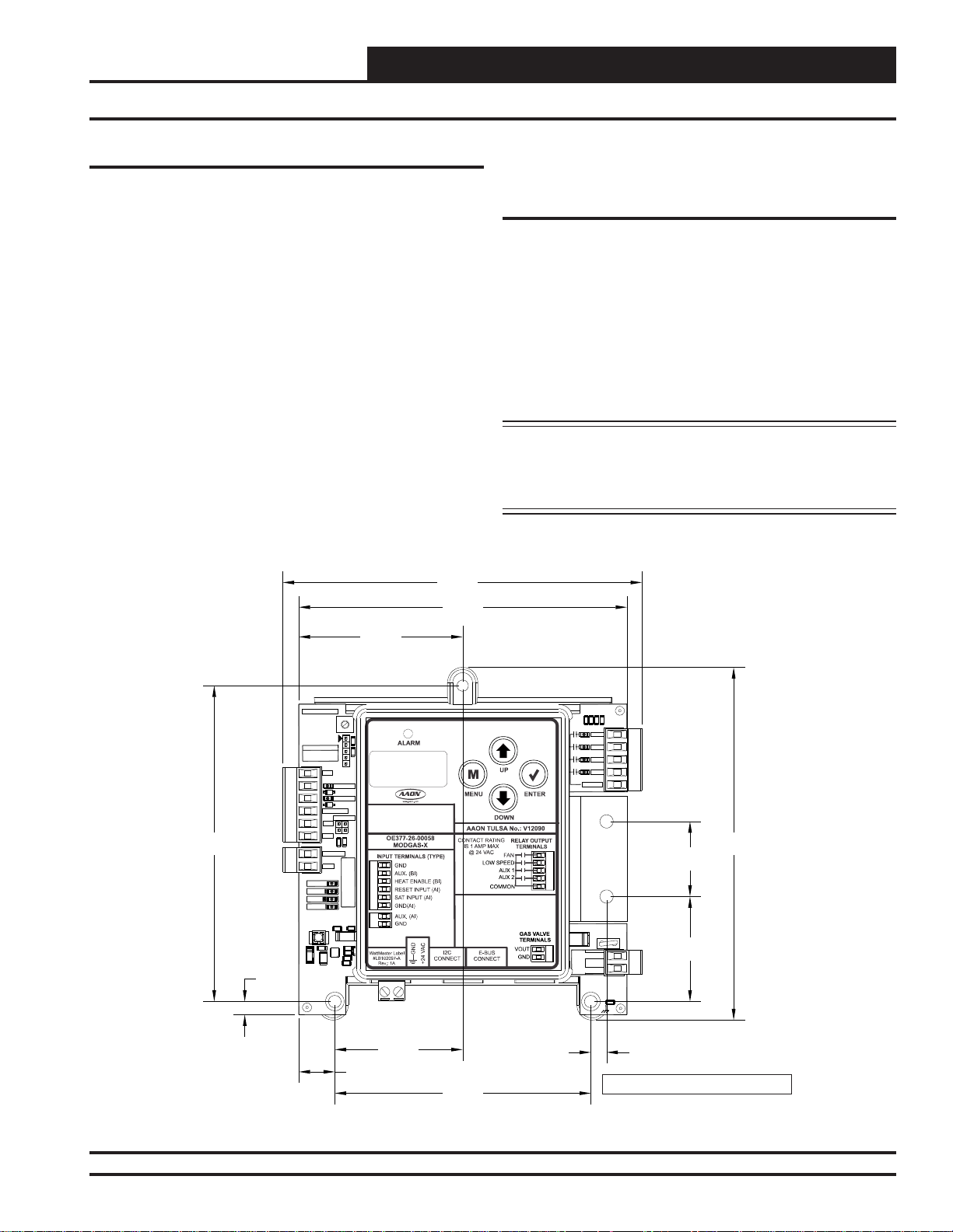
The OE377-26-00058 MODGAS-X Controller (AAON Part No.
V12090) is designed to modulate up to (2) gas valves to maintain
a desired Discharge Air Temperature. The MODGAS-X Controller
also controls the speed of the induced draft fan to maintain proper
combustion in the heat exchanger. See Figure 1 for dimensions.
The controller can be used as a stand-alone controller or communicating with an AAON Unit Controller. The MODGAS-X controller
connects to an AAON unit controller or expansion module via a
modular cable. Depending on the type of unit controller, this connection will utilize an I
page 5 for wiring details.
The MODGAS-X Controller can be confi gured at the factory for
one (1) modulating valve, two (2) staged modulating valves, or one
(1) or two (2) modulating with multiple fi xed staged valves (stand-
alone operation only).
The MODGAS-X Controller can be confi gured at the factory for the
®
MAXITROL
0-20 volt valve(s) or the MAXITROL® EXA STAR
0-10 volt stepper valve(s).
2
C connection or an E-BUS connection. See
See Appendix C, page 26 for depiction.
5.73
5.24
When using the MODGAS-X Controller to replace an existing
MODGAS II Controller, see Appendix B, page 25 for details.
Features
The MODGAS-X Controller provides the following:
• Monitors Supply Air Temperature and Supply Air Reset
and modulates gas valve(s) to maintain Setpoint
• Provides proper control of the Induced Draft Fan
• Provides additional options for Stand-Alone control
• Contains a 2 x 8 LCD character display and 4 buttons
that allow for status display, setpoint changes, and
force modes
NOTE: The MODGAS-X Controller contains no user-
serviceable parts. Contact qualifi ed technical
personnel if your
operating correctly.
MODGAS-X Controller is not
5.04
0.21
MADE IN USA
YS102378 REV 1
WATTMASTER
CONTROLS
TB2
TB4
STATUS
ALARM
COMM
POWER
C210
D210
C211
L210
.47uF
GND
RESET IN
SAT
GND
AUXAIN
GND
3.3uF
U210
AUX BIN
D12
HEATEN
D14
OPTIONS
R42
R210
1502
R7
1020
1002
R5
U1
1
2
J3
R39
SERIAL #
R2
C2
C212
.1uF
22uF
6042
1212
R
2803
R
1962
R
R
0.57
2.62
2.04
4.09
R30
R19
R22
R26
2211
2211
2211
2211
TB5
RLY1
RLY2
RLY3
RLY4
COMMON
1.20
D1
V1
TB1
VOUT
GAS
GND
VALVE
C18
.01uF
1.68
0.25
Note: Overall Depth is 1.49 inches.
5.63
Figure 1: OE377-26-00058 MODGAS-X Controller Dimensions (In Inches)
MODGAS-X Field Technical Guide
3
Page 4

WIRING
Important Wiring Considerations
Important Wiring Considerations
Please read carefully and apply the following information when
wiring the
requires the following electrical connections:
1.
2.
3. Supply Air Temperature Sensor and Heat Enable must have
4. All 24 VAC wiring must be connected so that all ground
5. All wiring is to be in accordance with local and
6. Check all wiring leads at the terminal block for tightness.
MODGAS-X Controller. The MODGAS-X Controller
18 gauge minimum wire unless otherwise noted.
24 VAC power connection with an appropriate VA rating.
24 gauge minimum wire.
wires remain common. Failure to follow this procedure can
result in damage to the module and connected devices.
national electrical codes and specifi cations.
Be sure that wire strands do not stick out and touch
adjacent terminals. Confi rm that all transducers required for
your system are mounted in the appropriate location and
wired into the correct terminals.
WARNING: Do Not Connect Power To VOUT/Ground
Terminal Block!
WARNING: Observe polarity! All boards must be wired
GND-to-GND and 24 VAC-to-VAC. Failure
to observe polarity could result in damage to
the board.
4
MODGAS-X Field Technical Guide
Page 5
WIRING
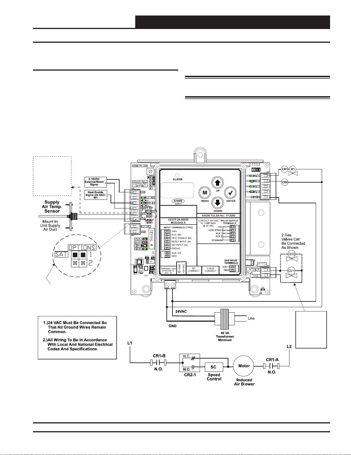
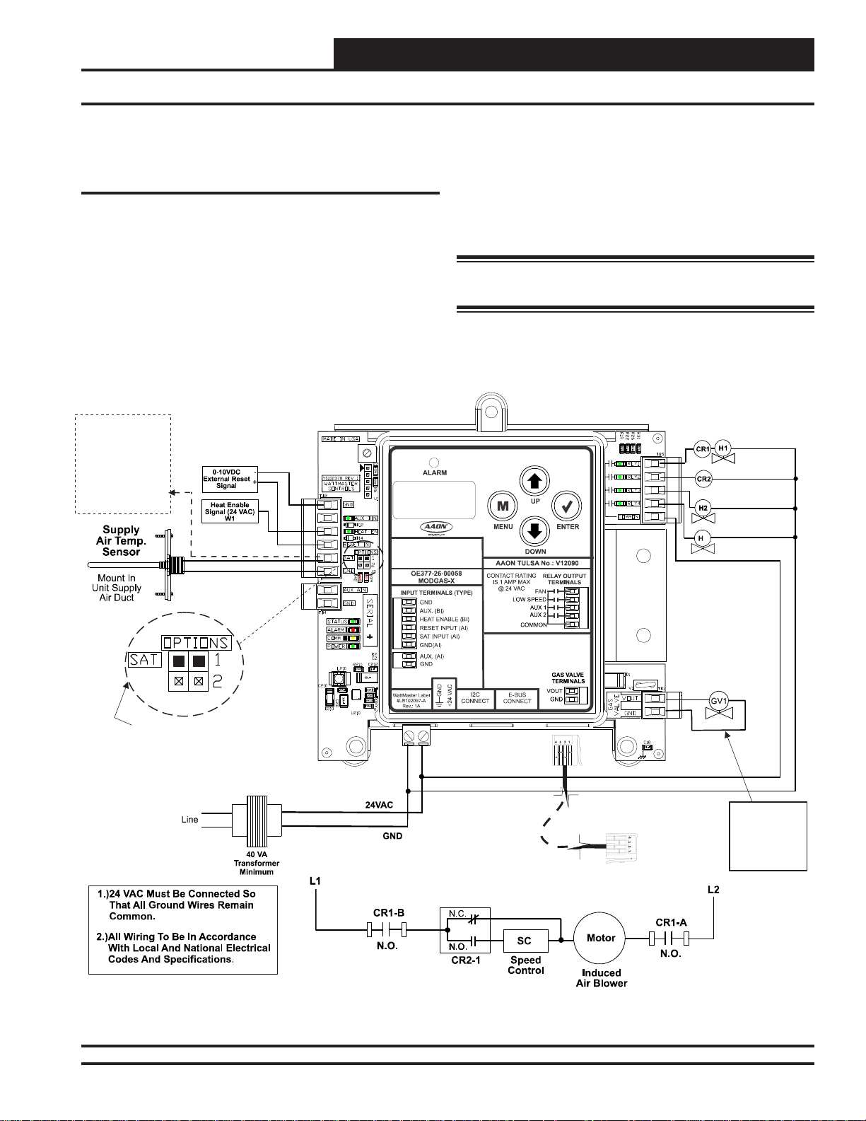
Single Modulating Valve No Staging - Stand-Alone Wiring
Single Modulating Valve No Staging Stand-Alone Wiring
This confi guration operates as Stand-Alone (Figure 2, below) or
communicating with an AAON Unit Controller (Figur e 3, page 6).
This confi guration can use either the MAXITROL® 0-20 volt valve(s)
or the MAXITROL® EXA ST AR 0-10 volt stepper valve(s)—confi g-
ured at the factory.
Connect SAT and
GND
Input to
Reheat
Board’s
SAT
Input If
Applicable.
Table 7,
See
Page 24
.
See Appendix C, page 26 for depiction.
MODGAS-X CONTROLLER
If using a MHGRV-X Controller along with the MODGAS-X
Controller in Stand-Alone, the SAT Sensor always connects to the
MODGAS-X Controller.
WARNING: Do Not Connect Power To VOUT/Ground
Terminal Block!
(OE377-26-00058)
Fan Enable And
Modulating Heat Enable
Low Speed Fan
See
For Settings.
Only One Supply Air Temperature Sensor
Table 8, Page 24
SAT OPTIONS Jumper
Can Be Used Per Application.
Figure 2: Single Modulating Valve No Staging Stand-Alone Wiring Diagram
MODGAS-X Field Technical Guide
24 VAC Power
Input Terminals
Max. Power
Consumption
1 Gas Valve
= 18 VA
2 Gas Valves
= 33 VA
5
Page 6
WIRING
Single Modulating Valve No Staging - Communicating Wiring
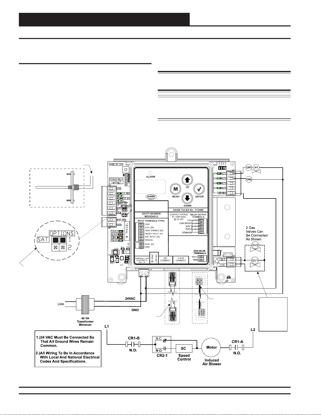
Single Modulating Valve No Staging Communicating Wiring
This confi guration operates as Stand-Alone (Figure 2, page 5) or
communicating with an AAON Unit Controller (Figure 3, below).
For connection to a VCB-X Controller or VCB-X Expansion Module, use an E-BUS Cable connecting to the appropriate E-BUS ports
on those controllers. For all other controllers, including VAV/CAV,
MUA, VCM, VCM-X, SA, and RNE Controllers, use an I
connecting to the appropriate I2C ports on those controllers.
Connect
Supply Air Temperature
Sensor T
(This Does Not Apply To
See .)
o AI2 & GND
On Main Controller
Retrofit Applications.
Table 7, Page 24
Supply
Air Temperature
Sensor
Mount In Supply
Air Duct
2
C Cable
MODGAS-X CONTROLLER
This confi guration can use either the MAXITROL® 0-20 volt valve(s)
or the MAXITROL
®
EXA ST AR 0-10 volt stepper valve(s)—confi g-
ured at the factory. See Appendix C, page 26 for depiction.
WARNING: Do Not Connect Power To VOUT/Ground
Terminal Block!
NOTE: If additional fi xed stages are required, these should be
confi gured and wired to the AAON Unit Controller’s
relays.
(OE377-26-00058)
Fan Enable And
Stage 1 Heat (Mod)
Low Speed Fan
The SAT OPTIONS Jumper Setting
Should Be Set to 1.
See For Settings.
Table 9, Page 24
Only One Supply Air Temperature Sensor
Can Be Used Per Application.
2
I C Cable
Connects To
2
I C Port On
Any Non VCB-X Controller
Or Expansion Module
Figure 3: Single Modulating Valve No Staging Communicating Wiring Diagram
6
MODGAS-X Field Technical Guide
EBC E-BUS Cable
Connects To
VCB-X Controller’s
Expansion
Port
24 VAC Power
Input Terminals
Max. Power
Consumption
1 Gas Valve
= 18 VA
2 Gas Valves
= 33 VA
Page 7
WIRING
Single Modulating Valve & Up To 14 Stages Fixed Heat Stand-Alone
One Modulating Valve With Up To 14
Additional Stages Of Fixed Heat
Stand-Alone Wiring
This confi guration only applies to a Stand-Alone operation (Figure
4, below) and is factory-confi gured.
If using a MHGRV-X Controller along with the MODGAS-X
Controller in Stand-Alone, the SAT Sensor always connects to the
MODGAS-X Controller.
MODGAS-X CONTROLLER
Connect SAT and
GND
Input to
Reheat
Board’s
SAT
Input If
Applicable.
Table 7,
See
Page 24
.
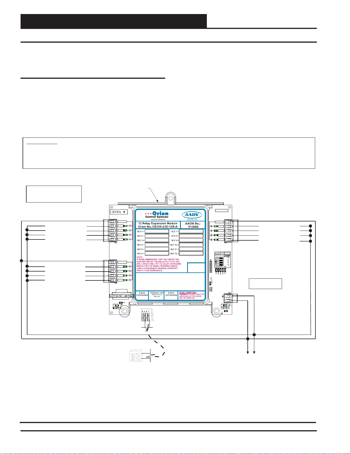
The fi rst two fi xed stages use AUX1 and AUX2 relays to enable
them (Figure 4, below). Additional fi xed stages can be added by
using the 12-Relay E-BUS Expansion Module. (Figure 5, page 8).
This configuration
can use either the MAXITROL® 0-20 volt
valve(s) or the MAXITROL® EXA STAR 0-10 volt stepper valve(s)
(confi gured at the factory). See Appendix C, page 26 for depiction.
WARNING: Do Not Connect Power To VOUT/Ground
Terminal Block!
(OE377-26-00058)
Fan Enable And
Stage 1 Heat (Mod)
Low Speed Fan
Stage 2 Heat (Fixed)
Stage 3 Heat (Fixed)
3
See
For Settings.
Only One Supply Air Temperature Sensor
Can Be Used Per Application.
Table 8, Page 24
SAT OPTIONS Jumper
Figure 4: Single Modulating Valve - Stand-Alone
MODGAS-X Field Technical Guide
EBC-E-BUS Cable
Connects To
12 Relay E-BUS
Expansion
Port
24 VAC Power
Input Terminals
Max. Power
Consumption
1 Gas Valve
= 18 VA
7
Page 8
WIRING
Single Modulating Valve & 14 Stages of Fixed Heat - Stand-Alone
One Modulating Valve With Up To 14
Additional Stages Of Fixed Heat
the MODGAS-X Controller will alarm and fall back to using only
its onboard stages. If communications is restored, the MODGAS-X
Controller will begin staging up if needed.
Stand-Alone Wiring, Continued
If communication is lost to the 12-Relay E-BUS Expansion Module,
the 12-Relay E-BUS Expansion Module will turn off its relays and
WARNING!!
Observe Polarity! All boards must be wired with GND-to-GND and 24VAC-to-24VAC. Failure to observe polarity will result in damage to
one or more of the boards. Expansion Modules must be wired in such a way that the expansion modules and the controller are always
powered together. Loss of power to the expansion module will cause the controller to become inoperative until power is restored to the
expansion module.
Note:
All Relay Outputs Are Normally Open
And Rated For 24 VAC Power Only.
1 Amp Maximum Load.
R1
Heat Stage 4 (Fixed)
R2
Heat Stage 5 (Fixed)
R3
Heat Stage 6 (Fixed)
R4
Heat Stage 7 (Fixed)
12-Relay E-BUS
Expansion Module
COM
RLY1
RLY2
RLY3
RLY4
RLY-COM
RLY1
RLY2
RLY3
RLY4
MADE IN USA
RLY-COM
RLY9
RLY10
RLY11
RLY12
COM
RLY9
RLY10
RLY11
RLY12
Heat Stage 12 (Fixed)
Heat Stage 13 (Fixed)
Heat Stage 14 (Fixed)
Heat Stage 15 (Fixed)
R9
R10
R11
R12
R5
Heat Stage 8 (Fixed)
R6
Heat Stage 9 (Fixed)
R7
Heat Stage 10 (Fixed)
R8
Heat Stage 11 (Fixed)
COM
RLY5
RLY6
RLY7
RLY8
EBC E-BUS Cable
Connect To MODGAS-X Controller
RLY-COM
RLY5
RLY6
RLY7
RLY8
RELAY
EXPANSION BOARD
YS102324 REV 2
GND
24VAC
GND
24 VAC
15 VA Minimum
Power Required
GND
24 VAC
Figure 5: Single Modulating Valve & 14 Stages of Fixed Heat - 12-Relay E-BUS Expansion Module
8
MODGAS-X Field Technical Guide
Page 9

WIRING
Two Modulating Valves & Up To 13 Stages Fixed Heat Stand-Alone
Two Modulating Valves With Up To 13
Additional Stages Of Fixed Heat
Stand-Alone Wiring
This confi guration only applies to a Stand-Alone operation (Figure
6, below) and is factory-confi gured.
In this confi guration, the fi rst Modulating Valve is enabled by the
FAN RLY. The second Modulating Valve is enabled by the AUX1
relay. The fi xed stage uses the AUX2 relay to enable it (Figure 6,
below). Additional fi xed stages can be added by using the 12-Relay
E-BUS Expansion Module. (Figure 7, page 10).
MODGAS-X CONTROLLER
Connect SAT and
GND
Input to
Reheat
Board’s
SAT
Input If
Applicable.
Table 7,
See
Page 24
.
If using a MHGRV-X Controller along with the MODGAS-X
Controller in Stand-Alone, the SAT Sensor always connects to the
MODGAS-X Controller.
This configuration
can use either the MAXITROL® 0-20 volt
valve(s) or the MAXITROL® EXA STAR 0-10 volt stepper valve(s)
(confi gured at the factory). See Appendix C, page 26 for depiction.
WARNING: Do Not Connect Power To VOUT/Ground
Terminal Block!
(OE377-26-00058)
Fan Enable And
Stage 1 Heat (Mod)
Low Speed Fan
Stage 2 Heat (Mod)
Stage 3 Heat (Fixed)
3
See
For Settings.
Only One Supply Air Temperature Sensor
Can Be Used Per Application.
Table 8, Page 24
SAT OPTIONS Jumper
Figure 6: Two Modulating Valves - Stand-Alone
MODGAS-X Field Technical Guide
EBC-E-BUS Cable
Connects To
12 Relay E-BUS
Expansion
Port
Revised 9/30/14
24 VAC Power
Input Terminals
Max. Power
Consumption
1 Gas Valve
= 18 VA
2 Gas Valves
= 33 VA
9
Page 10

WIRING
Two Modulating Valves & Up To 13 Stages Fixed Heat - Stand-Alone
Two Modulating Valve With Up To 13
Additional Stages Of Fixed Heat
the MODGAS-X Controller will alarm and fall back to using only
its onboard stages. If communications is restored, the MODGAS-X
Controller will begin staging up if needed.
Stand-Alone Wiring, Continued
If communication is lost to the 12-Relay E-BUS Expansion Module,
the 12-Relay E-BUS Expansion Module will turn off its relays and
WARNING!!
Observe Polarity! All boards must be wired with GND-to-GND and 24VAC-to-24VAC. Failure to observe polarity will result in damage to
one or more of the boards. Expansion Modules must be wired in such a way that the expansion modules and the controller are always
powered together. Loss of power to the expansion module will cause the controller to become inoperative until power is restored to the
expansion module.
Note:
All Relay Outputs Are Normally Open
And Rated For 24 VAC Power Only.
1 Amp Maximum Load.
R1
Heat Stage 4 (Fixed)
R2
Heat Stage 5 (Fixed)
R3
Heat Stage 6 (Fixed)
R4
Heat Stage 7 (Fixed)
12-Relay E-BUS
Expansion Module
COM
RLY1
RLY2
RLY3
RLY4
RLY-COM
RLY1
RLY2
RLY3
RLY4
MADE IN USA
RLY-COM
RLY9
RLY10
RLY11
RLY12
COM
RLY9
RLY10
RLY11
RLY12
Heat Stage 12 (Fixed)
Heat Stage 13 (Fixed)
Heat Stage 14 (Fixed)
Heat Stage 15 (Fixed)
R9
R10
R11
R12
R5
Heat Stage 8 (Fixed)
R6
Heat Stage 9 (Fixed)
R7
Heat Stage 10 (Fixed)
R8
Heat Stage 11 (Fixed)
COM
RLY5
RLY6
RLY7
RLY8
EBC E-BUS Cable
Connect To MODGAS-X Controller
RLY-COM
RLY5
RLY6
RLY7
RLY8
RELAY
EXPANSION BOARD
YS102324 REV 2
GND
24VAC
GND
24 VAC
15 VA Minimum
Power Required
GND
24 VAC
Figure 7: Two Modulating Valves & 13 Stages of Fixed Heat - 12-Relay E-BUS Expansion Module
10
Revised 9/30/14
MODGAS-X Field Technical Guide
Page 11

WIRING
Two Modulating Staged Valves - Stand-Alone Wiring
Two Modulating Staged Valves Wiring
In this confi guration, the fi rst Modulating Valve is enabled by the
FAN RLY. The second Modulating Valve is enabled by the AUX1
relay.
This confi guration operates as Stand-Alone (Figure 8, below) or
communicating with an AAON Unit Controller (Figur e 9, page 12).
MODGAS-X CONTROLLER
Connect SAT and
GND
Input to
Reheat
Board’s
SAT
Input If
Applicable.
Table 7,
See
Page 24
.
If using a MHGRV-X Controller along with the MODGAS-X
Controller in Stand-Alone, the SAT Sensor always connects to the
MODGAS-X Controller.
This confi guration
can use either the MAXITROL® 0-20 volt valve(s)
or the MAXITROL® EXA ST AR 0-10 volt stepper valve(s)—confi g-
ured at the factory. See Appendix C, page 26 for depiction.
WARNING: Do Not Connect Power To VOUT/Ground
Terminal Block!
(OE377-26-00058)
Fan Enable and
Stage 1 Heat (Mod)
Low Speed Fan
Stage 2 Heat (Mod)
See For
Table 8, Page 24
SAT OPTIONS Jumper
Only One Supply Air Temperature Sensor
Can Be Used Per Application.
Settings.
Figure 8: Two Modulating Staged Valves Stand-Alone Wiring Diagram
MODGAS-X Field Technical Guide
24 VAC Power
Input Terminals
Max. Power
Consumption
1 Gas Valve
= 18 VA
2 Gas Valves
= 33 VA
11
Page 12

WIRING
Two Modulating Staged Valves - Communicating Wiring
Two Modulating Staged Valves Communicating Wiring
This confi guration operates as Stand-Alone (Figure 8, page 11) or
communicating with an AAON Unit Controller (Figure 9, below).
For connection to a VCB-X Controller or VCB-X Expansion Module,
use an E-BUS Cable connecting to the appropriate E-BUS ports on
those controllers.
For all other controllers, including VAV/CAV, MUA, VCM, VCMX, SA, and RNE Controllers, use an I
appropriate I2C ports on those controllers.
Connect
Supply Air Temperature
Sensor T
(This Does Not Apply To
Retrofit Applications.
See .)
Mount In Supply
Air Temperature
o AI2 & GND
On Main Controller
Table 7, Page 24
Air Duct
Supply
Sensor
2
C Cable connecting to the
MODGAS-X CONTROLLER
If using the VCM-X Controller (I2C), extra fi xed stages can be added
by using the VCM-X Expansion Module.
This configuration
can use either the MAXITROL® 0-20 volt
valve(s) or the MAXITROL® EXA STAR 0-10 volt stepper valve(s)
(confi gured at the factory).
See Appendix C, page 26 for depiction.
WARNING: Do Not Connect Power To VOUT/Ground
Terminal Block!
(OE377-26-00058)
Fan Enable and
Stage 1 Heat (Mod)
Low Speed Fan
Stage 2 Heat (Mod)
The SAT OPTIONS Jumper Setting
Should Be Set to 1.
See For Settings.
Table 9, Page 24
Only One Supply Air Temperature Sensor
Can Be Used Per Application.
2
I C Cable
Connects To
VCM-X Controller’s
Expansion
Port
Figure 9: Two Modulating Staged Valves Communicating Wiring Diagram
12
MODGAS-X Field Technical Guide
EBC E-BUS Cable
Connects To
VCB-X Controller’s
Expansion
Port
24 VAC Power
Input Terminals
Max. Power
Consumption
1 Gas Valve
= 18 VA
2 Gas Valves
= 33 VA
Page 13

INPUTS & OUTPUTS
Inputs and Outputs
I/O Map
See Table 1 below to reference the inputs and outputs that are avail-
able on the MODGAS-X Controller.
Analog Inputs
1 (RST IN) Reset Signal
2 (SAT) Supply Temperature
3 (AUX AI) Not Used
Binary Inputs
1 (AUX BI) Not Used
2 (HEAT EN) Heat Enable
Analog Output (0-20 or 0-10 VDC)
1 (VOUT) Heat Valve
Relays
1 (FAN) Fan and Stage 1 Heat (Modulating)
2 (LOW SPEED) Low Speed Fan
3 (AUX 1) Stage 2 Heat (Fixed or Modulating)
4 (AUX 2) Stage 3 Heat (Fixed or Modulating)
Table 1: MODGAS-X Controller Inputs & Outputs
Binary Inputs
Heat Enable Contact (HEAT EN)
This input is only required when the controller is used in stand-alone
operation; it is not required when communicating with an AAON
Unit Controller. The Heat Enable input is activated by a 24VAC
signal supplied from a building automation system to enable the
MODGAS-X Controller. The controller will not operate without
24VAC being applied to this input terminal when used in a standalone confi guration. When the Heat Enable signal is lost or turned
off, all stages de-activate immediately.
This enable input can be used in communication mode for special
circumstances. Heat enable can be activated by either communications or this enable input. Heat enable will be deactivated when both
signals from communications and the enable input is turned off.
Analog Output
Gas Valve Output (VOUT)
Depending on the type of valve used, this output will supply a 0-20
VDC or 0-10 VDC output signal for control of the modulating gas
valve. With a 0-20 VDC valve, the operation is reverse acting, so
high voltage means closed and low voltage means open. With a 0-10
VDC valve, the operation is direct acting.
Analog Inputs
Reset Input (RST IN)
Used only in stand-alone operation. The Discharge Temperature
Setpoint can be reset by supplying a 0-10 VDC signal to the RST
IN low voltage terminal block. This reset signal is optional and need
only be used if you require resetting of the discharge air temperature.
Supply Air Temperature Sensor (SAT)
Used in stand-alone operation and when MODGAS-X is connected
to a CAV/VAV or MUA Controller. The Supply Air Temperature
Sensor is the control source. This sensor has to be installed for the
unit to operate. The Supply Air Sensor is located in the discharge
air stream and monitors discharge air temperature to maintain the
discharge air temperature setpoint.
WARNING: For 0-20 VDC valves, the maximum number
that can be connected/confi gured is 2. For 0-10 VDC valves,
the maximum number that can connected/confi gured is 4.
Relay Outputs
Relay #1 - Fan and Stage 1 Heat Modulating
When the MODGAS-X Controller has heat enabled, this relay closes
to bring the induced draft blower on at high speed. The controller
will activate the Low Speed Fan Relay to reduce the induced draft
blower speed as the gas valve modulates closed. This relay is also
used to enable Modulating Heat Valve 1.
Relay #2 - Low Speed Fan
Depending on the gas valve position, this relay will close to switch
the induced draft blower to low speed. The controller automatically
switches the blower to low speed as the gas valve modulates closed
in order to maintain the proper fuel to air ratio.
MODGAS-X Field Technical Guide
Revised 9/30/14
13
Page 14

OPERATION MODES
Outputs and Operation Modes
Relay #3 - Aux 1
Stage 2 Heat (Fixed or Modulating)—If confi gured for two
or more stages of heat, this relay would enable the 2nd stage of
heat if the 1st modulating valve cannot maintain the confi gured
supply air temperature setpoint. This stage and any additional
stages of heat will stage up and down as required to maintain
the Supply Air Temperature Setpoint. The Stage Up Delay default is 3 minutes. The Stage Down Delay default is 1 minute.
Relay #4 - Aux 2
Stage 3 Heat (Fixed or Modulating)—If confi gured for three or
more stages of heat, this relay would enable the 3rd stage of heat as
needed to maintain the confi gured supply air temperature setpoint.
This stage and any additional stages of heat will stage up and down
as required to maintain the Supply Air Temperature Setpoint. The
Stage Up Delay default is 3 minutes. The Stage Down Delay default
is 1 minute.
12-Relay E-BUS Expansion Module - Stand-Alone
Only
Stages 4-15 Heat (Fixed) These relays should only be used in
Stand-Alone confi guration when more than three stages of heat are
confi gured. These relays will successively stage up based on the
stage up delay to maintain the confi gured supply air temperature
setpoint. This stage and any additional stages of heat will stage
up and down as required to maintain the Supply Air Temperature
Setpoint. The Stage Up Delay default is 3 minutes. The Stage Down
Delay default is 1 minute.
Operation Modes
The MODGAS-X Controller can be used stand-alone or communicating with an AAON Unit Controller using a modular cable.
Stand-Alone Mode
When used in a stand-alone application, the MODGAS-X Controller
will modulate the gas valve(s) and stage any additional fi xed stages to
maintain the DISCHARGE setpoint confi gured on the MODGAS-X
Controller LCD display. The MODGAS-X Controller is activated
by a 24VAC signal to the HEAT EN input.
The following are available in Stand-Alone mode using the LCD
display on the MODGAS-X Controller:
• Status
• Supply Air Temperature Setpoint Adjustment
• Supply Air Reset Temperature Setpoint
Adjustment
• Force Mode ON/OFF
• Force Valve Position
• Force Relays
• Alarms
Communicating Mode
When the MODGAS-X Controller is connected and communicating
with an AAON Unit Controller via a modular cable, the necessary
information will be passed between the MODGAS-X and the Main
Unit Controller to properly operate in the Heating Mode.
If the communication is interrupted between the MODGAS-X
Controller and the Main Controller, both boards will show an alarm.
When communication is restored, the alarms will go away.
14
Revised 9/30/14
In this confi guration, the Supply Air Temperature Setpoint is set
using the Main Controller and the Supply Air Temperature Reset is
calculated by the Main Controller.
The following are available in communicating mode using the LCD
display on the MODGAS-X Controller:
• Status
• Force Mode ON/OFF
• Force Valve Position
• Force Relays
• Alarms
MODGAS-X Field Technical Guide
Page 15

LCD DISPLAY SCREENS
Navigation Keys
LCD Display Screen & Navigation
Keys
The MODGAS-X Controller allows you to make confi guration
changes, view status, change setpoints, create force modes, and
perform diagnostics using the keypad next to the LCD display. See
Figure 10 and refer to Table 2 for descriptions.
Figure 10: LCD Display and Navigation Keys
NAVIGATION
KEY
MENU
UP
DOWN
ENTER
Use the MENU key to navigate through the
Main Menu Screens.
Use this key to adjust setpoints and change
confi gurations. This key is also used to turn
Valve Force Mode on.
Use this key to adjust setpoints and change
confi gurations. This key is also used to turn
Valve Force Mode off.
Use the Enter key to move through screens
within Main Menu categories. Also, use this
key to save setpoints and confi guration
changes.
KEY FUNCTION
Table 2: Navigation Key Functions
MODGAS-X Field Technical Guide
15
Page 16

LCD DISPLAY SCREENS
Main Screens Map and MODGAS Screens
Main Screens Map
Refer to the following map when navigating through the LCD Main
Screens. The fi rst screen is an initialization screen. To scroll through
the rest of the screens, press the
Press to scroll through MODGAS Screens.
Press to go to STATUS Screens.
Press to scroll through STATUS Screens.
Press to go to ALARMS Screens.
<MENU> button.
MODGAS
STATUS
ALARMS
Main MODGAS Screens
Refer to the following map when navigating through the Main
Screens. From the MODGAS Screen, press
through the screens.
MODGAS
S/A MODE,
S/A MODE LOCKED
or COMM MODE
In Stand-Alone Mode, the screen will display S/A MODE or S/A MODE
LOCKED.
In Communications Mode, the screen will display COMM MODE and the
items below will scroll through the screen:
1. Number of good packets being received. This will roll over after 9999.
Example: +XXXX.
2. Number of checksum errors. This will stop at 9999. Example: C-XXXX
3. Number of packet length errors. This will stop at 9999 until power is
cycled. Example: P-XXXX.
4. Number of initialization errors if communication is I
Example: I-XXXX.
<ENTER> to scroll
2
C.
Alarms will display automatically.
Press to go to SETPOINTS Screens.
SETPOINT
Press to scroll through SETPOINTS Screens.
Press to go to FORCE Screens.
FORCE
VALVES
Press to scroll through FORCE Screens.
SOFTWARE
1044 V.XXX
CURRENT SOFTWARE VERSION
ADDRESS
1 (138)
CURRENT BOARD ADDRESS
Number in parentheses is E-BUS address.
# STAGES
T=2 M=2
NUMBER OF STAGES CONFIGURED
T = Total stages fi xed and modulating
M = Total modulating stages
16
Revised 9/30/14
MODGAS-X Field Technical Guide
Page 17

LCD DISPLAY SCREENS
Status & Alarm Screens
Status Screens
Refer to the following map when navigating through the Status
Screens. From the STATUS Screen, press
through the screens.
STATUS
Status Screens shown below will scroll automatically if LCD display is
left on this screen for 20 seconds.
MODE
HEAT
MODE
This screen displays the current mode of operation of the MODGAS-X
Controller. The mode options are:
OFF: This mode will display when there is no call for heat and heating
has been disabled.
HIGH FIRE: Each time Heat is activated, the unit will fi rst go into High
Fire Mode. During this mode, the unit will remain at maximum fi re. The
unit will leave this mode once proof of fi re has been established.
HEAT: After High Fire, the unit will enter the Heat Mode and will begin
to modulate the gas valve to maintain the Heating Supply Air Setpoint
(SAT). The unit must remain in this mode for a minimum run time of 1
minute. While in Heat Mode, the screen will display the staging status—
HEAT STAGE 1 to ST AGE 16. If Modulating Staged Heat, the screen will
display MOD HEAT. Once the call for heat goes away, the unit will leave
the Heat Mode.
CUTOFF: The Cutoff Mode occurs if the SAT rises above 200˚F. During
Cutoff Mode, the Heat will be disabled for a fi xed delay period. If the SA T
falls below 200˚F and the delay period has expired, the unit will re-enter
the Heat Mode.
FORCE: Force Mode.
SA T FAIL: The Supply Air Temperature sensor has been disconnected
for more than 60 seconds. This alarm will be disabled when the sensor
is reconnected.
VLV POS
100%
VALVE POSITION
0 to 100 percent
<ENTER> to scroll
SA TEMP
XX.X
SUPPL Y AIR TEMPERA TURE
40ºF to 200ºF or 5ºC to 93ºC.
If no sensor is detected, screen will display “NO SENSR”
ACTIV SP
XX.X
ACTIVE SUPPLY AIR SETPOINT
Calculated from SAT setpoint and reset signal in stand-alone mode. In
communicating mode, the Main Controller sends the setpoint.
FAN SPD
OFF,HIGH,LOW
FAN SPEED
OFF, HIGH, LOW
Alarm Screens
Refer to the following map when viewing Alarm Screens. These
screens will display automatically when alarms are present. For
alarm troubleshooting, see pages 19 & 20.
ALARMS
ALARMS
The alarms are as follows:
NO ALARMS: This will be shown if there are no current alarms.
SAT CUTOFF: This indicates a Supply Air Temperature Cutoff Alarm
condition which is activated if the SAT has risen above 200ºF. The alarm
will go away if after a fi xed delay period the SAT has dropped below
200ºF.
MECH FAILURE: The unit has been in High Fire Mode for more time
than the mechanical failure delay period. This alarm will be disabled
when the unit leaves High Fire Mode.
SA T FAIL ERROR: The Supply Air Temperature sensor has been dis-
connected for more than 60 seconds. This alarm will be disabled when
the sensor is reconnected.
COMM T/O ERROR: Communications have been lost with the main
controller. This alarm will disable when communications resume.
MODGAS-X Field Technical Guide
17
Page 18

LCD DISPLAY SCREENS
Setpoint & Force Screens
Setpoint Screens
Refer to the following map when navigating through the Setpoint Screens. From the SETPOINTS Screen, press
to scroll through the screens and change setpoints. Use the <UP>
and <DOWN> arrow keys to change your selections. Then press
<ENTER> to save the new setpoint.
NOTE: When the MODGAS-X is operating in
Communications Mode, these setpoint screens
will not appear on the LCD display because
they are controlled by the Main Controller.
SETPOINTS
SAT SP
40-200°F
5-93°C
HEATING SUPPLY AIR TEMPERATURE SETPOINT
This is the target temperature while the heating is enabled. If you are
using the reset signal, this is the setpoint it will calculate to at zero volts.
Will display only in stand-alone mode.
The SAT Setpoint is set by the LCD Display in stand-alone mode and is
set by the Main Controller in communicating mode.
<ENTER>
Force Screens
Refer to the following map when navigating through the Force
Screens. From the FORCE Screen, press
FORCE
VALVES
FORCE
MODE ON/OFF
Press the <UP> button to turn the Force Mode on.
Press the <DOWN> button to turn the Force Mode off.
FRC VALV
X%
FORCE VALVE PERCENTAGE
This screen only appears when Force Mode is on.
Press the <UP> button to increase the percentage.
Press the <DOWN> button to decrease the percentage.
NOTE: When you turn the Force Mode back off or after
1 hour has elapsed, the valve will reinitialize to zero.
<ENTER>.
Minimum Default Maximum
40°F
5°C
120°F
49°C
200°F
93°C
RESET SP
40-200°F
5-93°C
RESET HEATING SUPPLY AIR SETPOINT
This is the maximum temperature at which the Supply Air Temperature
will reset to. Will display only in stand-alone mode.
The Reset Setpoint is set by the LCD Display in stand-alone mode and
is set by the Main Controller in communicating mode.
Minimum Default Maximum
40°F
5°C
120°F
49°C
200°F
93°C
The next 15 screens are for Relays Only.
STAGE 1
MODULATING
This Relay cannot be forced.
STAGE 2-14
FORCE ON OR OFF
Press the <UP> button to turn the Force the Relay on.
Press the <DOWN> button to turn the Force the Relay off.
FORCE
TIMEOUT
FORCE MODE TIME OUT
This screen will appear when the Force Mode times out after 1 hour.
18
MODGAS-X Field Technical Guide
Page 19

TROUBLESHOOTING
LED Diagnostics & Alarms
LED Diagnostics
The MODGAS-X Controller is equipped with LEDs that can be used
to verify operation and perform troubleshooting. There are LEDs for
communication, operation modes, and diagnostic codes. The module
has 10 LEDs—8 used for operation & status, and 2 used for alarms.
See Figure 9, page 18 for the LED locations. The LEDs associated
with these inputs and outputs allow you to see what is active without
using a voltmeter. The LEDs and their uses are as follows:
Operation LEDs
POWER - This green LED will light up to indicate that 24 VAC
power has been applied to the controller.
STATUS - This green LED will light up and blink the board address
at startup. It will then blink every 10 seconds according to what mode
the controller is in. See Table 3.
No. of
Blinks
1 Off Mode
2 High Fire Mode
3 Heating Mode
4 Force Mode
Table 3: STATUS LED Blink Codes
Diagnostic LEDs
ALARM - This red LED located on the MODGAS-X Controller’s
cover above the LCD display will light up to indicate an alarm. The
type of alarm(s) will be shown on the LCD display. The ALARM
LED also blinks when the expansion valve is initializing at startup.
The ALARM LED on the MODGAS-X board will blink an alarm
code when an alarm(s) occurs. The highest priority failure code will
be indicated fi rst. Y ou must correct the highest priority alarm before
other problems will be indicated. See Table 4.
No. of
Blinks
1 Mechanical Failure
2 Supply Air Temperature Sensor
Failure
3 SAT Cutoff Mode
4 Communications Time Out Error
STATUS LED
ALARM LED
Communication LED
COMM - This yellow LED will light up and blink when communica-
tions are detected.
Relay LEDs
RLY1 - This green LED will light up and stay lit as long as the Fan
relay is active.
RLY2 - This green LED will light up and stay lit as long as the Low
Speed Fan relay is active.
RLY3 - This green LED will light up and stay lit as long as the
Auxiliary Heat relay is active.
Binary Input LEDs
AUX BIN - Not Used.
HEAT EN - This green LED will light up when Heat is enabled.
Troubleshooting Alarms
Mechanical Failure:
• Check relay outputs on the MODGAS-X for 24 VAC
output.
• Verify the SAT OPTIONS jumper settings on the
MODGAS-X for Supply Air Temperature Sensor.
• Verify output voltage (VOUT and GND) to gas valve.
Try forcing valves (refer to Force Screens in this
guide).
• Verify that the Supply Air Temperature Sensor is
connected to SAT and GND on the MODGAS-X
(stand-alone mode and when using VAV/CAV or
MUA Controller) or to AI2 and GND on the Main
Controller (communicating mode).
• Verify Supply Air Temperature Sensor probe is
mounted correctly in supply duct.
• Remove SAT and GND wiring from the MODGAS-X
and ohm the sensor out (this may indicate open or
failed wiring). Refer to chart in back of this guide for
readings.
Table 4: ALARM LED Blink Codes
MODGAS-X Field Technical Guide
19
Page 20

TROUBLESHOOTING
Alarms & LED Locations
Supply Air Temperature Failure:
• Verify that the Supply Air Temperature Sensor is
connected to the SAT and GND on the MODGAS-X
(stand-alone mode or when using Retrofi t
Applications. See Table 7, page 24.) or to AI2 and
GND on specifi c Main Controllers (communicating
mode). See Table 7, page 24.
• Remove SAT and GND wiring from MODGAS-X
and ohm the sensor out (this may indicate open or
failed wiring). Refer to chart in back of this guide for
readings.
• Verify the SAT OPTIONS jumper settings on the
MODGAS-X for the Supply Air Temperature Sensor.
Sat Cutoff Mode:
• Remove SAT and GND wiring from the MODGAS-X
and ohm the sensor out (this may indicate open or
failed wiring). Refer to chart in back of guide for
readings.
• With Supply Air Sensor disconnected from the
MODGAS-X, set volt meter to DC volts and measure
voltage between SAT and GND on board. Refer to
Tables 5 & 6, pages 21 & 22 for readings.
• Verify Supply Air Temperature Sensor reading in duct
with 3rd party temperature testing device.
Communications Loss:
• Check COMM LED on MODGAS-X.
• Verify 24 VAC power to all interconnected
WattMaster controllers.
• Verify connection between the MODGAS-X
and associated WattMaster controllers.
• In communication mode (connected to a an AAON
Unit with modular cable), confi rm that Unit
Controller’s MODGAS-X status screen displays
MODGAS-X’s Supply Air Temperature and that Main
MODGAS screens show COMM MODE.
MODGAS-X CONTROLLER
(OE377-26-00058)
NOT USED
HEAT ENABLE LED
STATUS LED
ALARM LED
COMM LED
POWER LED
ALARM LED
FAN LED
LOW SPEED FAN LED
AUXILIARY HEAT LED
NOT USED
Figure 11: MODGAS-X Controller LED Locations and Descriptions
20
MODGAS-X Field Technical Guide
Page 21

TROUBLESHOOTING
SAT Sensor Testing
Other Checks
0-3V (SAT OPTIONS Jumper Setting 1) & 0-5V
(SAT OPTIONS Jumper Setting 2) Supply Air
Temperature Sensor
If you suspect the Supply Air Temperature Sensor is not reading
correctly, make sure the wiring terminal connections are tight and
that any wiring splices are properly connected. You can check the
operation of the Supply Air Temperature Sensor by measuring the
resistance or voltage using a digital multimeter. Set the meter to DC
Volts. Place the positive probe on the AIN terminal and the negative
probe on the GND terminal. Read the DC Volts and fi nd that voltage
in Tables 5 & 6, below & page 22.
Read the temperature corresponding with that voltage and determine
if this is close to the actual temperature the sensor is exposed to. If the
temperature from the chart is different by more than a few degrees,
you probably have a defective or damaged sensor. You can also
check the sensor resistance to determine correct operation. To read
the resistance, set the meter to Ohms. Unplug the sensor connector
from the board and measure the resistance across the disconnected
wires. This resistance should match the corresponding temperature
from Tables 5 & 6, below & page 22.
Temperature to Resistance/Voltage Chart
Temp
(°F)
-10 -23.3 93333 2.98
-5 -20.6 80531 2.94
0 -17.8 69822 2.89
5 -15.0 60552 2.83
10 -12.2 52500 2.77
15 -9.4 45902 2.71
20 -6.7 40147 2.64
25 -3.9 35165 2.57
30 -1.1 30805 2.49
35 1.6 27140 2.41
40 4.4 23874 2.33
45 7.2 21094 2.24
50 10.0 18655 2.15
52 11.1 17799 2.11
54 12.2 16956 2.08
56 13.3 16164 2.04
58 14.4 15385 2.00
60 15.6 14681 1.96
Table 5: 0-3V Temperature Sensor - Voltage &
Resistance for Type III Sensors
Temp
(°C)
Resistance
(Ohms)
Voltage @
Input (VDC)
Temperature to Resistance/Voltage Chart
Temp
(°F)
62 16.7 14014 1.93
64 17.8 13382 1.89
66 18.9 12758 1.85
68 20.0 12191 1.81
69 20.6 11906 1.79
70 21.1 11652 1.78
71 21.7 11379 1.76
72 22.2 11136 1.74
73 22.7 10878 1.72
74 23.3 10625 1.70
75 23.9 10398 1.68
76 24.4 10158 1.66
78 25.6 9711 1.63
80 27.8 9302 1.59
82 27.8 8893 1.55
84 28.9 8514 1.52
86 30.0 8153 1.48
88 31.1 7805 1.45
90 32.2 7472 1.41
95 35.0 6716 1.33
100 37.8 6047 1.24
105 40.6 5453 1.16
110 43.3 4923 1.09
115 46.1 4449 1.02
120 48.9 4030 .95
125 51.7 3656 .88
130 54.4 3317 .82
Temp
(°C)
Resistance
(Ohms)
Voltage @
Input (VDC)
Table 5, continued: 0-3V Temperature Sensor Voltage & Resistance for Type III Sensors
Thermistor Sensor Testing Instructions
1.) Use the resistance column to check the thermistor sensor while
disconnected from the controllers (not powered).
2.) Use the voltage column to check sensors while connected to
powered controllers. Read voltage with meter set on DC volts. Place
the “-” (minus) lead on GND terminal and the “+” (plus) lead on the
sensor input terminal being investigated.
If the voltage is above 3.3 VDC, the sensor or wiring is “open.” If
the voltage is less than 0.05 VDC, the sensor or wiring is shorted.
MODGAS-X Field Technical Guide
21
Page 22

TROUBLESHOOTING
SAT Sensor Testing
Temperature to Resistance/Voltage Chart
Temp
(°F)
-10 -23.3 93333 4.620
-5 -20.6 80531 4.550
0 -17.8 69822 4.474
5 -15.0 60552 4.390
10 -12.2 52500 4.297
15 -9.4 45902 4.200
20 -6.7 40147 4.095
25 -3.9 35165 3.982
30 -1.1 30805 3.862
35 1.6 27140 3.737
40 4.4 23874 3.605
45 7.2 21094 3.470
50 10.0 18655 3.330
52 11.1 17799 3.275
54 12.2 16956 3.217
56 13.3 16164 3.160
58 14.4 15385 3.100
60 15.6 14681 3.042
62 16.7 14014 2.985
64 17.8 13382 2.927
66 18.9 12758 2.867
68 20.0 12191 2.810
69 20.6 11906 2.780
70 21.1 11652 2.752
71 21.7 11379 2.722
72 22.2 11136 2.695
73 22.7 10878 2.665
74 23.3 10625 2.635
75 23.9 10398 2.607
76 24.4 10158 2.577
78 25.6 9711 2.520
80 27.8 9302 2.465
82 27.8 8893 2.407
84 28.9 8514 2.352
86 30.0 8153 2.297
88 31.1 7805 2.242
90 32.2 7472 2.187
95 35.0 6716 2.055
Temp
(°C)
Resistance (Ohms) Voltage @
Input (VDC)
Temperature to Resistance/Voltage Chart
Temp
(°F)
100 37.8 6047 1.927
105 40.6 5453 1.805
110 43.3 4923 1.687
115 46.1 4449 1.575
120 48.9 4030 1.469
125 51.7 3656 1.369
130 54.4 3317 1.274
135 57.2 3015 1.185
140 60.0 2743 1.101
145 62.8 2502 1.024
150 65.6 2288 0.952
Temp
(°C)
Resistance (Ohms) Voltage @
Input (VDC)
Table 6, cont.: 0-5V Temperature Sensor - Voltage
& Resistance for Type III Sensors
Thermistor Sensor Testing Instructions
1.) Use the resistance column to check the thermistor sensor while
disconnected from the controllers (not powered).
2.) Use the voltage column to check sensors while connected to
powered controllers. Read voltage with meter set on DC volts. Place
the “-” (minus) lead on GND terminal and the “+” (plus) lead on the
sensor input terminal being investigated.
If the voltage is above 5.08 VDC, the sensor or wiring is “open.” If
the voltage is less than 0.05 VDC, the sensor or wiring is shorted.
Table 6: 0-5V Temperature Sensor - Voltage &
Resistance for Type III Sensors
22
MODGAS-X Field Technical Guide
Page 23

APPENDIX A
Supply Air Temperature Sensor Installation
Mounting the Supply Air Temperature
Sensor
• The Supply Air Temperature (SAT) Sensor should be
located in the duct-work downstream of the unit supply
air connection.
• Locate the sensor in the center of the widest part of the
duct. Use the supplied template and a 5/16” drill to make
a hole for the sensor.
• Install the gasket over the probe and mount securely to
the duct using the supplied sheet metal screws. Be sure
the gasket is compressed to provide an air tight seal.
• For best accuracy, apply insulation on the outside of the
duct, over the sensor. This will help prevent thermal
gradients from affecting the sensor.
WARNING: Make sure your Supply Air Temperature
Sensor is mounted and wired according to
these instructions prior to testing the unit or
else the modulating valve will not control
properly and may damage your equipment.
Stand-Alone Mode
In Stand-Alone Mode, the SA T Sensor is connected to the MODGASX Controller. If, in Stand-Alone Mode, the MODGAS-X Controller
is used in conjunction with a Stand-Alone MHGRV Controller, the
SA T sensor is shared between the two controllers and always attaches
to the MODGAS-X Controller.
See Table 8, page 24 for SAT Options Jumper Settings and see
Figures 2, 4, and 5 - 8 for wiring. See Table 7, page 24 for details
about retrofi t applications.
Communication Mode
When communicating with AAON Unit Controllers, the SAT Sensor
will be connected to the Main Controller. The exception would be
in retrofi t applications with older controllers. See Table 9, page 24
for SAT Options Jumper Settings and see Figur es 3 & 9 for wiring.
See Table 7, page 24 for details about retrofi t applications.
Leads Are Non-Polarized. Butt Splice Leads
To 24 Gauge Wire Minimum.
In Stand Alone Applications And In Retrofit
Applications, Connect Leads to “SAT” And “GND” On
MODGAS-X Controller. See .
If Using A VCM-X, SA, RNE, Or VCB-X Controller,
Connect Leads To “AI2” And “GND” On Main Controller.
Table 7, Page 24
Figure 12: Supply Air Temperature Sensor Installation
MODGAS-X Field Technical Guide
23
Page 24

APPENDIX A
SAT Sensor Wiring Guide & Jumper Settings
SAT Wiring Conditions
MODGAS-X ONLY MHGRV-X ONLY MODGAS-X & MHGRV-X
STAND-
ALONE
VCB-X Install Supply Air Sensor
VCM-X,
SA, RNE
VCM,
VAV/CAV,
MUA,
MUA II,
MUA IID
Install Supply Air
Sensor in MODGAS-X.
in VCB-X.
Connect to VCB-X
using E-BUS cable.
Install Supply Air Sensor
in Main Controller.
Connect to Main
Controller using I
cable.
Install Supply Air Sensor
in MODGAS-X.
Connect to Main
Controller using I2C
cable.
2
C
Install Supply Air
Sensor in MHGRV-X.
Set “SAT Options”
Jumpers to “Normal”.
Install Supply Air
Sensor in VCB-X.
Connect to VCB-X
using E-BUS cable.
Install Supply Air
Sensor in Main Controller.
Connect to Main
Controller using I2C cable.
Install Supply Air
Sensor in MHGRV-X.
Connect to Main
Controller using I2C cable.
Table 7: SAT Wiring Conditions
SAT Options Jumper Settings
Refer to T ables 8 & 9 to determine the settings. See Figur e 2, page
5 for jumper locations.
STAND-ALONE MODE
SAT OPTIONS JUMPER SETTINGS*
CONDITION SETTING
MODGAS-X Only 1
MODGAS-X with
MHGRV-X** 1
MODGAS-X with
MHGRV II*** 2
MODGAS-X with
MHGRV III 2
* For SAT Sensor testing, use Table 5, page 21 for
jumper setting 1 and Table 6, page 22 for jumper
setting 2.
** In this situation, also set MHGRV-X SAT Option
to MODGAS-X. See the MHGRV-X Technical
Guide for more information.
*** The MHGRV II must have PU resistor installed.
Install Sensor in MODGAS-X and daisy-chain it
to the MHGRV-X. Set “SAT Options” Jumpers to
“MODGAS X”. If connected to a MODGAS II
Retrofi t, Set “SAT Options” Jumpers to “MODGAS”.
Install Supply Air Sensor in VCB-X.
Connect to VCB-X using E-BUS cable.
Install Supply Air Sensor in Main Controller.
Connect to Main Controller using I
Install Supply Air Sensor in MODGAS-X.
Connect to Main Controller using I2C cable.
COMMUNICATIONS MODE
SAT OPTIONS JUMPER SETTINGS*
CONDITION SETTING
VCM-X / RNE / SA* 1
VCM, MUA, MUA II,
MUA IID VAV/CAV** 1
VCB-X* 1
* For SAT Sensor testing, use Table 5, page 21 for
jumper setting 1. SAT should be connected to the
Main Controller.
** For SAT Sensor testing, use Table 5, page 21
for jumper setting 1. SAT should be connected to
the MODGAS-X Controller.
2
C cable.
Table 9: Communications Mode SAT OPTIONS
Jumper Settings
Table 8: Stand-Alone Mode SAT OPTIONS Jumper
Settings
24
Revised 6/18/13
MODGAS-X Field Technical Guide
Page 25

APPENDIX B
MODGAS-X Replacement of MODGAS II
Replacing the MODGAS II with the
MODGAS-X
The retrofi t replacement involves a few easy steps. Refer to Figure
13, below.
WARNING: Do Not Connect Power To VOUT/Ground
Terminal Block!
STAND-ALONE MODE OPERATION
Step 1: Disconnect power from the MODGAS II Controller.
Step 2: Disconnect the Supply Air Temperature Sensor from the
MODGAS II and wire it to the MODGAS-X. If the Supply
Air Temperature Sensor is being shared with a Stand Alone MHGRV Controller, maintain the same wiring
with the MHGRV Controller.
MODGAS-X CONTROLLER
Step 3: Wire all other inputs and outputs per Figure 2, page 5.
Step 4:
Set the SAT Options Jumper per Table 8, page 24.
Step 5: Connect power to the MODGAS-X Controller.
COMMUNICATIONS MODE OPERATION
Step 1: Disconnect power from the MODGAS-X Controller.
Step 2: The Supply Air Temperature Sensor needs to remain
installed on whatever controller it is currently on. If it
is currently installed on the MODGAS II Controller, then
reinstall it on the MODGAS-X Controller.
Step 3:
Set the SAT Options Jumper per Table 9, page 24.
Step 4: Connect power to the MODGAS-X Controller.
(OE377-26-00058)
See Tables 8 & 9, Page 24
For
SAT OPTIONS
Settings.
Jumper
Only One Supply Air
Temperature Sensor
Can Be Used Per Application.
See Table 7, Page 24
For Connection Settings.
2
I C Cable
Connects To
Main Controller’s
Expansion
Port
WARNING!: Do
Not Connect
Power To The
VOUT/Ground
Terminal Block!
Figure 13: MODGAS-X Controller
MODGAS-X Field Technical Guide
25
Page 26
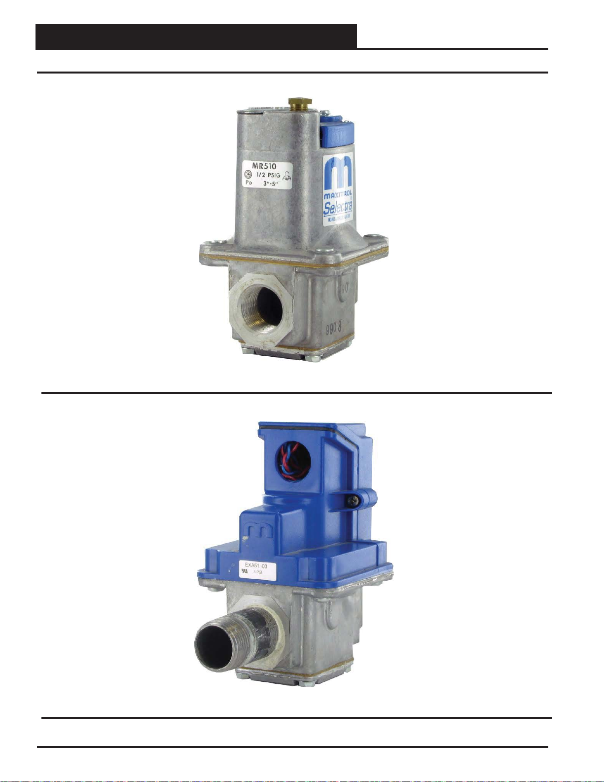
APPENDIX C
MAXITROL® Stepper Valve Types
Figure 14: 2-Wire 0-20 Volt Reverse Acting MAXITROL® Selectra Stepper Valve
Figure 15: 4-Wire 0-10 Volt Direct-Acting MAXITROL® EXA STAR Stepper Valve
26
Revised 1/31/14
MODGAS-X Field Technical Guide
Page 27

NOTES
MODGAS-X Field Technical Guide
27
Page 28

www.aaon.com
2425 So. Yukon Ave • Tulsa, OK 74107-2728
Ph: (918) 583-2266 • Fax: (918) 583-6094
AAON® Manual Part No. V16940
WattMaster Manual Form No: AA-MODGASX-FIELD-TGD-01F
 Loading...