

Page 1

r
FACTORY CONTROLS SYSTEM
MODGAS II Controlle
Installation &
Operations Manual
Page 2

r
FACTORY CONTROLS SYSTEM
MODGAS II Controlle
For Modulating Gas Heating Applications
Installation &
Operations Manual
This document is subject to change without notice.
WattMaster Controls, Inc. or AAON Inc. do not assume responsibility
for errors or omissions herein.
AAON MODGAS Controller
Installation & Operations Manual - Form WM-MG2-IOM-01C
AAON is a registered trademark of AAON, Inc.
Copyright 2010 WattMaster Controls, Inc.
All rights reserved.
Page 3

Section 1
Table of Contents
Component Overview....................................................... 1
MODGAS II Controller............................................................................................................... 1
Blink Codes for Status LED ........................................................................................................ 2
Supply Air Temperature Sensor .................................................................................................. 4
Component Wiring............................................................ 5
MODGAS II Controller............................................................................................................... 5
Board Inputs & Outputs ................................................... 7
Analog Inputs .............................................................................................................................. 7
Relay Outputs .............................................................................................................................. 7
Setting DIP Switches .......................................................8
Discharge Air Temperature ......................................................................................................... 8
Discharge Air Temperature Reset Limit...................................................................................... 8
Table of Figures
Figure 1-1: MODGAS II Controller Component Locations.................................................... 2
Table 1-1: Diagnostic LED Blink Codes ................................................................................. 2
Figure 1-2: MODGAS II Controller Dimensions.................................................................... 3
Figure 1-3: Supply Air Sensor Installation.............................................................................. 4
Figure 1-4: MODGAS II Controller Wiring............................................................................ 5
Figure 1-5: MODGAS II Controller DIP Switch Settings...................................................9
Overview & Wiring
Page 4

Page 5

MODGAS II Controller Section 1
Component Overview
MODGAS II Controller
The MODGAS II Controller is designed to modulate a gas valve to maintain a desired Discharge
Air Temperature. It also controls the speed of the induced draft fan to maintain proper
combustion in the heat exchanger. The controller can be used as a stand-alone unit or be
connected to the AAON HVAC unit controller as an expansion board.
The MODGAS II Controller has the following inputs and outputs:
4 Inputs:
• Supply Air Temperature Sensor • HEAT EN Input (24VAC)
• Discharge Air Temperature Reset Signal from a
control automation system (0-10VDC)
• AUX Input (not used)
4 Outputs:
• Fan Enable (relay) • LO SPEED fan control (relay)
• AUX Output (relay / not used*) • Gas Valve Analog Output (0-20VDC)
* If using EPROM SS0056 V 2.20 or higher, the AUX Output Relay is functional. Once the MODGAS II
Controller brings on heat, if the Supply Air Temperature rises 5˚F and the valve output has reached 90%,
then the AUX Relay will activate to bring on a 2
modulate as needed to maintain the Heating Supply Air Setpoint. If the modulating valve falls below 30%,
the AUX Relay will disable.
When used in a stand-alone application (not connected to an AAON HVAC unit controller
board), the MODGAS II Controller will modulate the gas valve to maintain the DISCHARGE
setpoint set by the DIP switch on the board. The MODGAS II Controller is activated by a 24VAC
signal to the HEAT EN input.
When the MODGAS II Controller is connected to an AAON HVAC unit controller via the
modular cable, the following information will be passed between the MODGAS II and the
AAON HVAC unit controller.
nd
stage of fixed heat. The modulating valve is then able to
• Heat activation command • The offset for the Supply Air
Temperature Sensor.
• Hi Limit Temperature Setpoint. • Heating Discharge Setpoint. This replaces the
setpoint that is set with the Discharge Air
Temperature DIP switch on the MODGAS II
Controller.
• If the communication is interrupted
between the MODGAS II Controller
and the AAON HVAC unit controller,
the MODGAS II Controller will
revert to stand-alone operation.
Overview and Wiring 1-1
Page 6
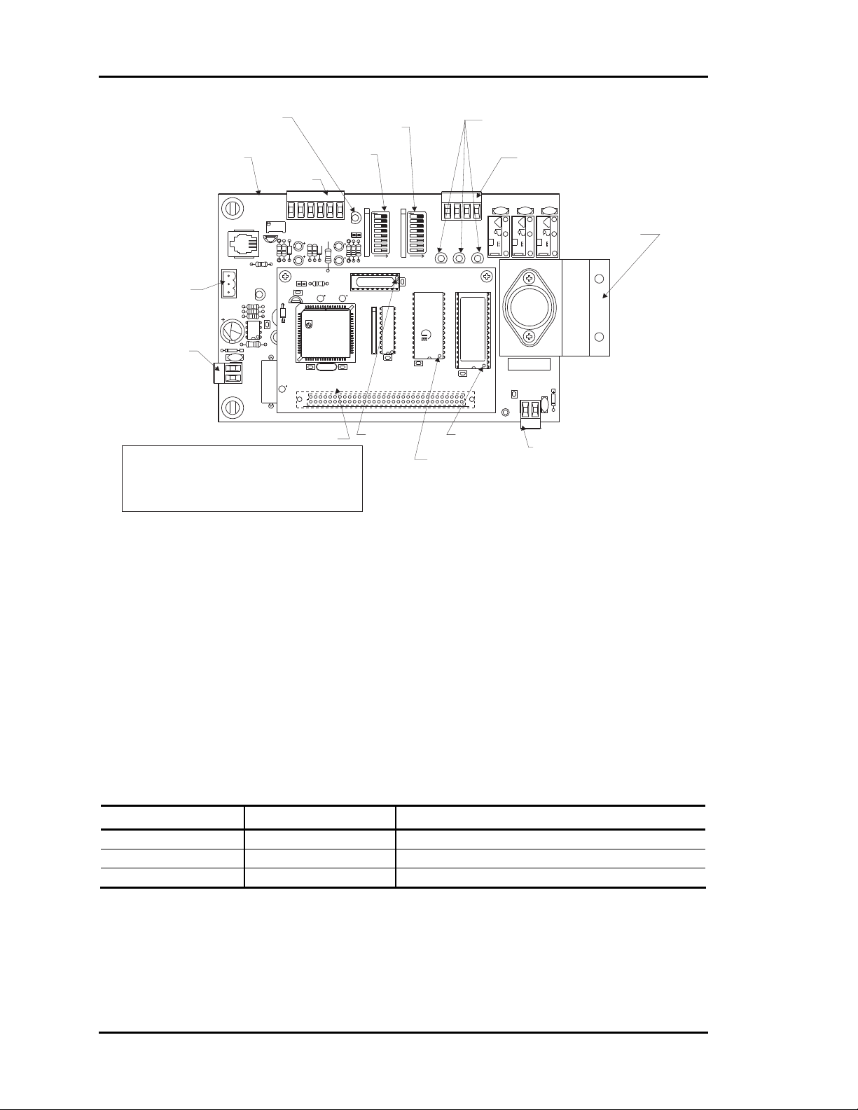
Section 1 MODGAS II Controller
Status LED
Modulating Gas
Controller Board
These Terminals
Not Used For
This Application
24 VAC Power
Input Terminals
(See Note 1 & 2)
Max. Power
Consumption
1 Gas Valve =15VA
2 Gas Valves = 30VA
C6
I2C IN
POWER
TB3
TB2
R26
R26
R25
Analog Input
Terminals
YS101826PREV 1
MODULATING
GAS BOARD
PJ1
R15
R
SHLD
POWER
T
C7
U5
D8
V4
24VAC
GND
P1
RV1
+VDC
VR1
R7
D1
P
WDOG
CX6
U6
U1
C4
552 Processor Board
Notes:
1.)24 VAC Must Be Connected So That All Ground
Wires Remain Common.
2.)All Wiring To Be In Accordance With Local And
National Electrical Codes And Specifications.
Discharge Setpoint
Reset Limit
DIP Switch
RST IN
SAT
AUX IN
GND
HEAT EN
C1
C2
R8
D2
R9
R2
CX1
PHILIPS
PHILIPS
C2
YS101818
P1
552 PROCESSOR
BOARD
DIP Switch
STATUS
RESET
LIMIT
F
F
J01
ADD
R1R3R1
P
U2
C3
R1
1
CX5
C1
PAL Chip
Pin 1
Relay Output
LEDs
Relay Output
Terminals
DISCHARGE
SETPOINT
TB1
O
O
F
F
1
1
2
4
8
16
32
64
128
R4
CX2
U5
2
4
8
16
32
64
128
ADD
RAM
CX4
RAM Chip
Pin 1
LO SPD
FAN
LOSPD
FAN
U4
CX3
V1 V3K3V2
K1
AUX
COM
AUX
EPROM
U3
C13
EPROM Chip
Pin 1
K2
FT
SER.#:
GAS
VALVE
GND
TB4
VOUT
V5
Gas Valve
Output
Terminals
Heat Sink
Must Be Fastened
With Sheet Metal
Screws
To A Sheet Metal
Surface
D9
Figure 1-1: MODGAS II Controller Component Locations
Blink Codes for Status LED
The MODGAS II Controller uses an on-board LED to indicate various diagnostic conditions
during power-up and operation. The LED is labeled “STATUS”. Starting with power up, the LED
blink codes are as follows:
• One Blink
• Off for five seconds
• Blinks 30 times
• Blinks 3 times rapidly
• Status code repeatedly blinks every ten seconds to indicate controller status:
Priority No. of Blinks Status
Lowest 1 Normal Operation
- 2 SAT Over High Limit
Highest 3 Bad SAT Sensor
Table 1-1: Diagnostic LED Blink Codes
Only the highest priority failure code will be shown. You must correct the highest priority alarm
before other problems will be indicated.
1-2 Overview and Wiring
Page 7
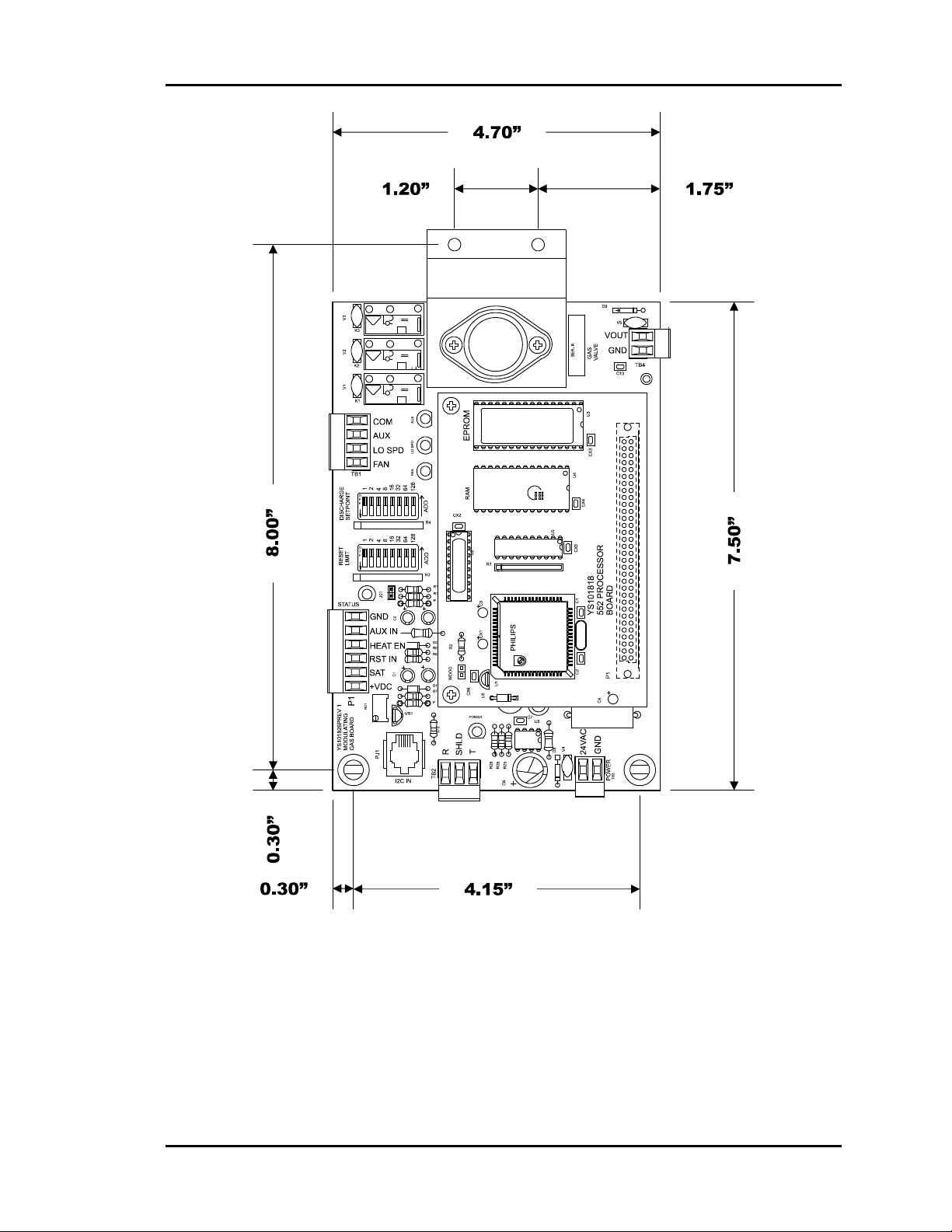
MODGAS II Controller Section 1
Figure 1-2: MODGAS II Controller Dimensions
Overview and Wiring 1-3
Page 8

Section 1 MODGAS II Controller
Supply Air Temperature Sensor
The supply air temperature sensor should be located in the ductwork downstream of the unit
supply air connection. Locate the sensor in the center of the widest part of the duct. Use the
supplied template and a
and mount securely to the duct using the supplied sheet metal screws. Be sure the gasket is
compressed to provide an air tight seal. For best accuracy, apply insulation on the outside of the
duct, over the sensor. This will help prevent thermal gradients from affecting the sensor.
5
/16" drill to make a hole for the sensor. Install the gasket over the probe
Figure 1-3: Supply Air Sensor Installation
1-4 Overview and Wiring
Page 9

MODGAS II Controller Section 1
Component Wiring
MODGAS II Controller
Figure 1-4: MODGAS II Controller Wiring
The MODGAS II Controller wiring is straightforward but allows for flexibility to set the system
up exactly as required for the specific application. All wiring should follow the minimum wire
sizing information that follows.
Overview and Wiring 1-5
Page 10

Section 1 MODGAS II Controller
Warning: Use extreme care not to damage any of the electronic components while
mounting the controller. Mark the holes and then remove the MODGAS II
Controller before drilling. Do not allow metal shavings to fall
onto the circuit boards.
The MODGAS II Controller requires the following electrical connections:
18 Gauge minimum unless otherwise noted.
-24VAC Supply Voltage.......................................................................................2 Conductors
-Supply Air Temperature Sensor ...................................................(24 Ga. Min.) 2 Conductors
-Heat Enable................................................................................... (24 Ga. Min.) 2 Conductors
Tip: After making all electrical connections, it is advised that you unplug all terminal blocks
on the MODGAS II Controller until you are ready to begin the checkout procedure.
This may help to prevent damage if wiring errors occur elsewhere in the system during
installation or start-up.
1-6 Overview and Wiring
Page 11

MODGAS II Controller Section 1
Board Inputs & Outputs
Analog Inputs
Input #1 - Heat Enable Contact (HEAT EN)
This input is only required when the controller is used in stand-alone operation; it is not
required when used as an expansion board to other unit controllers.The Heat Enable input
is activated by a 24 VAC signal supplied from a building automation system to enable the
MODGAS II Controller. The controller will not operate without 24 VAC being applied to
this input terminal when used in a stand-alone configuration.
Input #2 - Supply Air Temperature Sensor (SAT)
The Supply Air Temperature Sensor is the control source. This sensor has to be installed
for the unit to operate. The Supply Air Sensor is located in the discharge air stream and
monitors discharge air temperature to maintain the discharge air temperature setpoint.
Input #3 - Reset Input (RST IN)
The Discharge Temperature Setpoint can be reset by supplying a 0-10 VDC
signal to the RST IN low voltage terminal block. This reset signal is optional and need
only be used if you require resetting of the discharge air temperature.
Relay Outputs
Relay #1 - Fan Enable (FAN)
This relay works in conjunction with the LO SPEED relay to control the speed of the
induced draft blower motor. When the MODGAS II Controller has heat enabled, this
relay closes to bring the induced draft blower on at high speed. The controller will
activate the LO SPEED relay to reduce the induced draft blower speed as the gas valve
modulates closed.
Relay #2 - Fan Low Speed (LO SPD)
Depending on the gas valve position, this relay will close to switch the induced draft
blower to low speed. The controller automatically switches the blower to low speed as
the gas valve modulates closed in order to maintain proper fuel to air ratios.
Relay #3 - AUX Output (AUX)
If using EPROM SS0056 V 2.20 or higher, the AUX Output Relay is functional. Once
the MODGAS II Controller brings on heat, if the Supply Air Temperature rises 5˚F and
the valve output has reached 90%, then the AUX Relay will activate to bring on a 2
stage of fixed heat. The modulating valve is then able to modulate as needed to maintain
the Heating Supply Air Setpoint. If the modulating valve falls below 30%, the AUX
Relay will disable.
Gas Valve Output (VOUT)
This output is designed to supply a 0-20 VDC output signal for control of the modulating
gas valve. Up to two gas valves may be connected to this output if required by the
application. Do Not Connect More Than Two Gas Valves.
nd
Overview and Wiring 1-7
Page 12

Section 1 MODGAS II Controller
Setting DIP Switches
Discharge Air Temperature
This switch is only used when the controller is operated in stand-alone mode. The main unit
controller will set the discharge setpoint when the MODGAS II is used as an expansion device.
The user can set the desired Discharge Air Temperature Setpoint using the DIP Switch
labeled DISCHARGE SETPOINT. See Figure 1-5 for location and DIP Switch setting
instructions. The MODGAS II Controller will allow the user to set a Discharge Air
Temperature Setpoint between 40°F and 200°F. If a value of less than 40°F is set, the
controller will default to a 40°F Discharge Air Temperature Setpoint, a value greater
than 200°F will cause the unit to default to a 140°F Discharge Air Temperature
Setpoint.
Discharge Air Temperature Reset Limit
The user can reset the Discharge Air Temperature Setpoint by supplying a 0-10VDC
control signal to the Reset Input (RST IN) terminal on the MODGAS II Controller
board. The reset range is determined by the RESET LIMIT DIP Switch. See Figure 1-5 for
location and setting instructions. The controller will reset the Discharge Air Temperature
Setpoint from the value set on the DISCHARGE SETPOINT DIP Switch to the value set on the
RESET LIMIT DIP Switch, as the Reset Input (RST IN)
signal is increased from 0Volts to 10Volts.
Example:
We want the Discharge Air Temperature Setpoint to increase from 70°F when the Reset Input
signal is at 0 Volts to 130°F when the Reset Input signal is at 10 Volts.
• Set the DISCHARGE SETPOINT DIP Switch to 70°F
• Set the RESET LIMIT DIP Switch to 130°F
The discharge air temperature will now increase from 70°F to 130°F as the Reset Input voltage
signal ramps from 0 Volts to 10 Volts.
1-8 Overview and Wiring
Page 13

MODGAS II Controller Section 1
NOTE: It is possible to create a “reverse acting” control sequence by setting the
DISCHARGE SETPOINT DIP Switch to 130°F and the RESET LIMIT DIP
Switch to 70°F. In this case the controller will maintain a 130°F discharge
temperature when the Reset Input signal is at 0 Volts and will reduce it to 70°F
when the Reset Input signal is at 10 Volts.
Reset Limit DIP Switch
YS101826PREV 1
MODULATING
GAS BOARD
P1
RV1
RST IN
SAT
+VDC
PJ1
I2C IN
TB2
C6
POWER
TB3
VR1
R15
R
SHLD
POWER
T
R26
R26
R25
C7
U5
D8
V4
24VAC
GND
HEAT EN
C1
R8
R9
R7
D1
P
WDOG
R2
CX6
U6
U1
PHILIPS
PHILIPS
C2
C4
P1
MODGAS II Controller Board
64+32+16+8=120
Discharge Setpoint DIP Switch
AUX IN
GND
C2
D2
CX1
STATUS
J01
P
C3
C1
YS101818
552 PROCESSOR
BOARD
DISCHARGE
RESET
LIMIT
O
F
F
1
2
4
8
16
32
64
128
ADD
R1R3R1
U2
R1
1
CX5
SETPOINT
R4
CX2
U5
TB1
O
F
F
1
LO SPD
FAN
2
4
8
16
32
64
LOSPD
FAN
128
ADD
RAM
U4
CX4
CX3
AUX
EPROM
COM
AUX
V1 V3K3V2
K1
U3
All Rocker Switches Depressed
In the Direction Of The ADD Arrow
Are Added Together To Total The Setpoint
K2
FT
SER.#:
GAS
VALVE
GND
C13
TB4
D9
VOUT
V5
128+2=130
O
F
F
1
2
4
8
16
32
64
128
ADD
Typical DIP Switch
Detail View
ADD
DIP Switch Setting Shown
Is For A Setpoint Of 120
ADD
DIP Switch Setting Shown
Is For A Setpoint Of 130
Figure 1-5: MODGAS II Controller DIP Switch Settings
Overview and Wiring 1-9
Page 14

Section 1 MODGAS II Controller
1-10 Overview and Wiring
Page 15

Section 2
Table of Contents
Hand Held Service Tool LCD/Keypad Operations............ 1
Data Entry Functions................................................................................................................... 1
Menu Screens ..................................................................2
Main Menu Screen #1 ................................................................................................................. 2
View Status......................................................................2
MODGAS II Controller Status .................................................................................................... 2
Change Setpoints............................................................. 3
MODGAS II Controller Setpoints............................................................................................... 3
Summary Screen.............................................................. 5
MODGAS II Controller Summary .............................................................................................. 5
Programming
Page 16

Page 17

MODGAS II Controller Section 2
Hand Held Service Tool
LCD/Keypad Operations
Initialization Screen
Initializing
Service Tool v1.22
Mod Heat Controller
Wattmaster Controls
The screen shown above is displayed for a few seconds after the service tool is powered up. This
screen displays the current version of the software installed in your service tool.
The remainder of this section will lead the user through the system menus and keypad operations.
Data Entry Functions
A - Abort
B - Backup
C - Clear
D - Negative
* - Decimal
# - Enter
Used to exit from screens or from data entry.
Use this key to return to the Main Menu from
any screen in the system.
The user can step backwards to previous
screens or setpoints by pressing this key.
If a data entry mistake is made, press this
key to clear the data entry field and start
over.
If the user is entering a setpoint that is
negative in value, press this key for the
minus sign.
Use this key as the decimal point when
entering decimal values.
This key is used to close a data entry field
and advance to the next item or screen.
Programming 2-1
Page 18

Section 2 MODGAS II Controller
Menu Screens
After initialization, you will be advanced to the Main Menu screen. All status and setpoint
screens are accessed from this screen and additional menu screens are also accessed from this
Main Menu screen.
Main Menu Screen #1
1) View Status
2) Change Setpoints
3) Summary Screen
View Status
MODGAS II Controller Status
Accessed from Main Menu Screen #1 – Menu Item #1
The following status screens will appear when this menu item is selected and the selected unit is a
Modulating Gas Heat Controller. Step to each additional screen by pressing the “#” key. Press the
“A” key to exit before all status screens have been viewed. If the unit doesn’t respond, the data on
the screen will not be valid, although you can still step through the screens to get an idea of what
is displayed on each status screen. Use the “B” key to step backwards through the Status Screens.
Note: The top line of every status screen displays the same message that identifies the type
of unit you accessed. (Mod-Heat Controller)
Status Screen #1
Mod-Heat Controller
No Signal To Run
Supply Air: xxx.x°F
Line 2 -
Line 3 -
No Signal To Run = A signal has not initiated
controller operation.
W1 Signal Active = A signal has initiated controller
operation.
Supply Air xxx.x°F = Supply Air Temperature in
degrees Farenheit
2-2 Programming
Page 19

MODGAS II Controller Section 2
Status Screen #2
Mod-Heat Controller
MAX Setpoint: xxx°F
MIN Setpoint: xxx°F
Line 2 -
Line 3 -
Max Setpoint = This is the value from the RESET
LIMIT DIP switch on the MODGAS II Controller.
This is the value that the controller will use as the
Discharge Temperature Setpoint when the RESET
INPUT voltage signal is at 10 VDC.
NOTE: It is acceptable for this value to be less than
the MIN Setpoint for reverse acting control schemes.
Min Setpoint = This is the value from the
DISCHARGE SETPOINT Dip switch on the
MODGAS II Controller. This is the value that the
controller will use as the Discharge Temperature
Setpoint when the RESET INPUT voltage signal is at
0 VDC or when the no reset signal is connected.
Change Setpoints
MODGAS II Controller Setpoints
Accessed from Main Menu Screen #1 – Menu Item #2
Setpoint Screen #1
Controller Setpoints
Proportional. Kp: xx
Integral......Ki: xx
Setpoint Screen #2
Controller Setpoints
Derivative Kd.: xxx
Unwind Signal..:xxx
Kp = the proportional constant value for the PID loop. This
value affects the process stability of the PID loop.
Ki = the Integral constant value of the PID loop. This value is
used to eliminate positioning error on the PID loop.
Proportional Kp 1 20 70
Integral Ki 0 5 90
Kd = The derivative constant value of the PID loop. This value is
used to change the anticipation function on the PID loop.
The Integral Unwind value accounts for non-linear effects and
limitations in the valve.
Minimum Default Maximum
Derivative Kd 0 5 90
Unwind Signal 0 5 30
Programming 2-3
Minimum Default Maximum
Page 20

Section 2 MODGAS II Controller
Setpoint Screen #3
Controller Setpoints
PID LOOP PERIOD
Seconds......: xxx s
This value represents the sampling interval of the PID loop. It
indicates the time in seconds between calculations.
Minimum Default Maximum
PID LOOP Period 0 sec. 15 sec. 100 sec.
Setpoint Screens #4
Controller Setpoints
Switch To HI Speed
Fan Above Sig: xxx%
This is the percentage open of the modulating gas valve where the
Hi-Speed fan is required for proper induced airflow in the heat
exchanger.
Switch To HI Speed
Minimum Default Maximum
0% 40% 100%
Fan Above Sig
Setpoint Screens #5
Controller Setpoints
SUPPLY CUT-OFF
Temp. Above..: xxx°F
If the Supply Air Temperature ever exceeds this value, the
MODGAS II Controller will immediately be disabled. In order
for the MODGAS controller to be re-enabled (resume normal
operation), the temperature must drop 10°F below this setpoint.
Temp Above
Setpoint Screens #6
Controller Setpoints
Sensor Calibration
SAT: xx.x° xx.x°
The Thermistor Type III sensor readings can be calibrated. Enter
a Positive value to increase a reading and a Negative value to
decrease a reading.
Supply Sensor SAT
Minimum Default Maximum
50°F 150°F
300°F
Minimum Default Maximum
-100.0° 0.0°F +100.0°F
2-4 Programming
Page 21

MODGAS II Controller Section 2
Summary Screen
MODGAS II Controller Summary
Accessed from Main Menu Screen #1 – Menu Item #3
OFF SAT xxx SP xxx
VLV xxx % Fan OFF
BRN1 OFF
O xx.x N xx.x D xx.x
Line 1 -
Line 2-
Line 3 -
Line 4 -
OFF – ON = Indicates if unit is off or on.
SAT = Supply Air Temperature at unit discharge in
degrees Fahrenheit.
SP = Setpoint Temperature currently being used by the
controller in degrees Fahrenheit.
VLV xxx % = Percentage that valve is open.
FAN – Off – Lo Speed – High Speed = Indication of fan
condition and speed.
BRN1 = Indicates the status of the burner. This value is
either ON or OFF.
O = Old Error – The previous error calculation.
N = New Error – Difference between the setpoint and the
current temperature.
D = Desired Position – The position the valve is driving
towards.
Programming 2-5
Page 22

Form: WM-MG2-IOM-01C Printed in the USA March 2010
All rights reserved
WattMaster Controls Inc. • 8500 NW River Park Drive • Parkville MO • 64152
Phone (816) 505-1100
Copyright 2010
E-mail: mail@wattmaster.com
2425 So. Yukon Ave • Tulsa, OK 74107-2728
Ph: (918) 583-2266 • Fax: (918) 583-6094
Fax (816) 505-1101
AAON Part No. R02950
 Loading...