

Page 1

Factory Packaged Controls
MHGRV-X Controller
Field Technical Guide
Page 2
TABLE OF CONTENTS
CONTROLLER OVERVIEW ............................................................................................................... 3
Features ...................................................................................................................................................................3
INSTALLATION & WIRING ............................................................................................................... 4
Important Wiring Considerations ..............................................................................................................................4
MHGRV-X Controller to AAON Unit Controller Wiring..............................................................................................5
MHGRV-X Stand Alone Wiring .................................................................................................................................6
INPUTS AND OUTPUTS .................................................................................................................. 7
OPERATION OVERVIEW .................................................................................................................. 8
Initialization ..............................................................................................................................................................8
Modulating Hot Gas Valves ......................................................................................................................................8
Modes of Operation .................................................................................................................................................8
Additional Features ..................................................................................................................................................8
LCD DISPLAY SCREENS .................................................................................................................. 9
TROUBLESHOOTING ..................................................................................................................... 13
Using LEDs to Verify Operation .............................................................................................................................13
Temperature Sensor Testing ........................................................................................................................................14
APPENDIX A - Supply Air Temperature Sensor Guide ................................................................. 17
Supply Air Temperature Sensor Installation ........................................................................................................... 17
Supply Air Temperature Sensor Wiring Chart and Jumper Settings ......................................................................18
APPENDIX B .................................................................................................................................. 19
MHGRV-X Replacement of MHGRV II ...................................................................................................................19
APPENDIX C .................................................................................................................................. 20
Reheat Expansion Module .....................................................................................................................................20
PART NUMBER CROSS REFERENCE TABLE
PART DESCRIPTION
MHGRV-X Controller OE377-26-00059 V12100
Reheat Expansion Module OE377-01-00059 V42450
MODGAS-X Controller OE377-26-00058 V12090
Supply Air Temperature Sensor OE231 P87140
EBC E-BUS Cables - Varying Lengths EBC-XXX-F N/A
www.aaon.com
ORION
AAON
TULSA
2
WattMaster Controls Inc.
8500 NW River Park Drive · Parkville, MO 64152
Toll Free Phone: 866-918-1100
PH: (816) 505-1100 · FAX: (816) 505-1101
E-mail: mail@wattmaster.com
Visit our web site at www.orioncontrols.com
WattMaster Form: AA-MHGRVX-FIELD-TGD-01H
Copyright April 2015 WattMaster Controls, Inc.
AAON® Manual Part No.: V16950
®
AAON
is a registered trademark of AAON, Inc., Tulsa, OK.
Neither WattMaster Controls, Inc. nor AAON® assumes any
responsibility for errors or omissions in this document.
This document is subject to change without notice.
MHGRV-X Field Technical Guide
Page 3
OVERVIEW
MHGRV-X Controller General Information
Overview
The OE377-26-00059 MHGRV-X Controller (AAON Part
No. V12100) is designed to control a Modulating Hot Gas Reheat Valve to maintain a desired Supply Air Temperature setpoint. The controller can be used as a stand-alone controller
or can be used in conjunction with any AAON unit controller.
In addition, up to (7) Reheat Expansion Modules can be connected to
the Controller and to each other for additional Reheat V alve Control.
The MHGRV-X controller connects to an AAON unit controller or
expansion module via a modular cable. Depending on the type of
unit controller, this connection will utilize an I
E-BUS connection.
When using the MHGRV-X Controller to replace an existing
MHGRV II Controller, see Appendix B, page 19 for details.
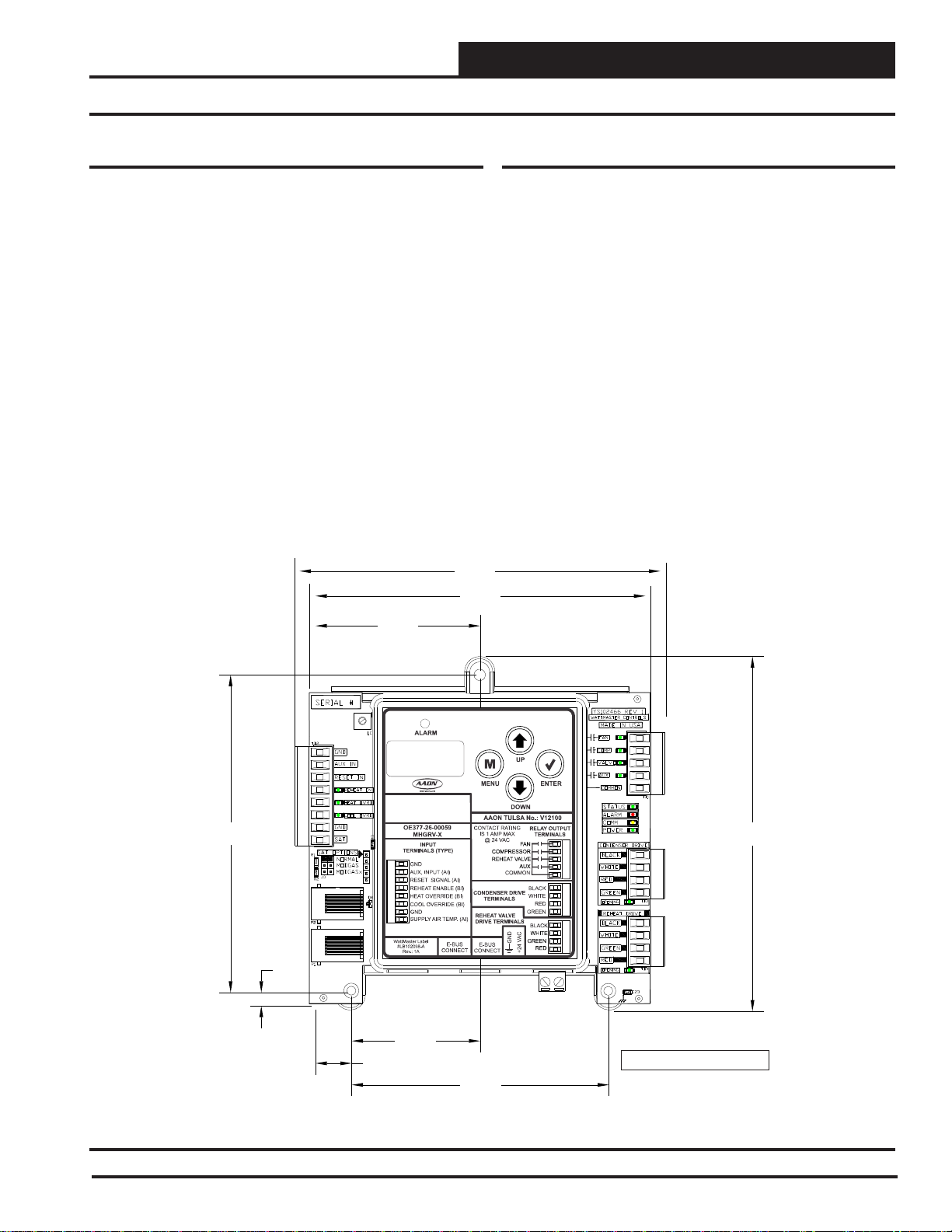
See Figure 1 for dimensions (in inches).
2
C connection or an
5.73
5.24
Features
The MHGRV-X provides the following:
Can be operated as a stand-alone controller or
communicating with AAON unit controllers.
Provides for Supply Air Temperature Setpoint
reset when required
Second stage reheat capability when using
2 Hot Gas Reheat Valves
Control of reheat solenoid valve to provide coil
fl ushing for positive refrigerant oil return
Can provide further Reheat control using up to (7)
Reheat Expansion Modules
Contains a 2 x 8 LCD character display and 4 buttons
that allow for status display, setpoint changes, and
confi guration changes
5.04
0.21
2.62
0.57
5.63
2.04
Note: iDepth s 1.49 inches.
4.09
Figure 1: OE377-26-00059 MHGRV-X Controller Dimensions
MHGRV-X Field Technical Guide
3
Page 4

WIRING
Installation & Wiring
Installation & Mounting
The MHGRV-X Controller is housed in a plastic enclosure. It
is designed to be mounted by using the 3 mounting holes in the
enclosure base. It is important to mount the module in a location
that is free from extreme high or low temperatures, moisture, dust,
and dirt. Be careful not to damage the electronic components when
mounting the module.
NOTE: The MHGRV-X Controller contains no user-serviceable
parts. Contact qualifi ed technical personnel if your Con-
troller or Module is not operating correctly.
General Wiring Information
Depending on if the MHGRV-X Controller is to be connected to
the HVAC controller or is to be used as a stand-alone controller
determines how the MHGRV-X should be wired. For the wiring
diagram to use when the MHGRV-X Controller is connected to an
AAON Unit Controller, see Figure 2, page 5. For the stand-alone
wiring diagram, see Figure 3, page 6.
For Reheat Expansion Module wiring, see Figure 9, page 22.
Please carefully read and apply the following information when
wiring the MHGRV-X controller and its expansion board(s):
1. 18 gauge minimum wire unless otherwise noted.
24 VAC power connection with an appropriate VA rating.
2.
3. Supply Air Temperature Sensor and Heat Enable must have
24 gauge minimum wire.
4. All 24 VAC wiring must be connected so that all ground
wires remain common. Failure to follow this procedure can
result in damage to the module and connected devices.
5. All wiring is to be in accordance with local and
national electrical codes and specifi cations.
6. Check all wiring leads at the terminal block for tightness.
Be sure that wire strands do not stick out and touch
adjacent terminals. Confi rm that all transducers required for
your system are mounted in the appropriate location and
wired into the correct terminals.
4
MHGRV-X Field Technical Guide
Page 5
WIRING
MHGRV-X to AAON Unit Controller Wiring
Communications Wiring
For connection to a VCB-X Controller, VCB-X Expansion Module,
and Reheat Expansion Module, use an E-BUS Cable to connect to
the appropriate E-BUS port on those modules and/or controller.
For all other controllers, including the VAV/CAV, MUA,VCM,
VCM-X, SA, and RNE Controllers, use an I
the appropriate I
2
C ports on those controllers.
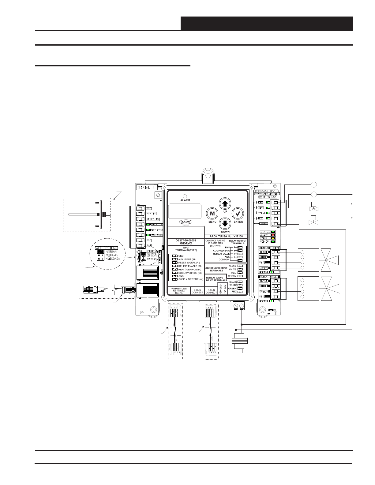
Connect
Supply Air Temperature
o AI2 & GND
Sensor T
On Main Controller
(This Does Not Apply To
CAV/VAV Or MUAApplications)
Supply
Air Temperature
Sensor
Mount In Supply
Air Duct
2
C Cable connecting to
MHGRV-X CONTROLLER
(OE377-26-00059)
When connected to an AAON Unit Controller, the Supply Air
Temperature Sensor is attached to the Main Controller. See Figure
2 below.
See the SAT Wiring Conditions Table and SAT OPTIONS jumper
settings in Tables 7 & 9, page 18.
Fan
C1
Compressor
C2
HGR Solenoid Valve
2 Position HGR Valve (Optional)
COMM
See
Table 9 On Page 18
For
SAT OPTIONS
Settings.
Jumper
Only One Supply Air
Temperature Sensor Can Be
Used Per Application.
Any Non VCB-X Controller Or
2
I C Cable
Connects To
2
Port On
IC
Expansion Module
EBC E-BUS Cable
Connects To
VCB-X Expansion
Port When Used
With VCB-X
Controller
EBC
E-BUS
Cable
Connects
To Reheat
Expansion
Module
GND
24VAC
Transformer
Minimum
Line
Condenser Valve #1
BLK
WHT
RED
GRN
BLK
WHT
GRN
RED
HGR Valve #1
40 VA
Figure 2: MHGRV-X Controller to AAON Unit Controller Wiring
MHGRV-X Field Technical Guide
5
Page 6
WIRING
MHGRV-X Stand-Alone Wiring
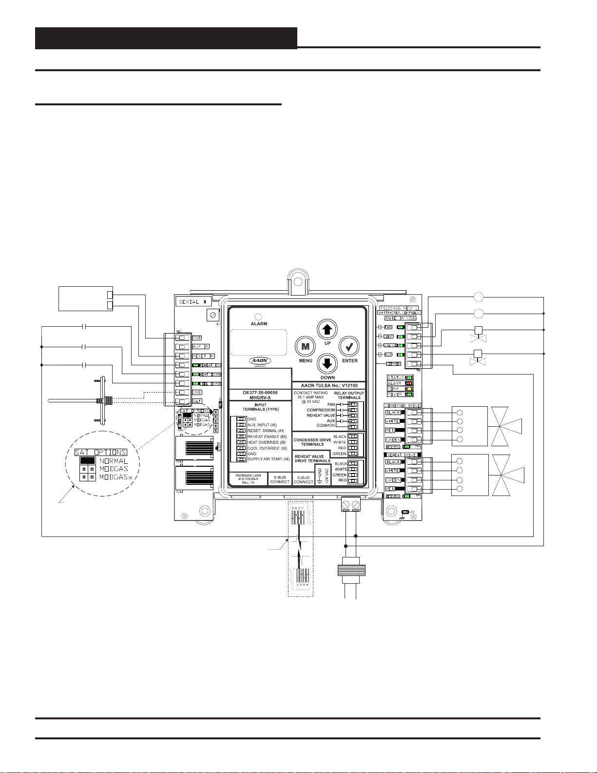
Stand-Alone Wiring
In Stand-Alone mode, the MHGRV-X connects to the E-BUS port
of the Reheat Expansion Module with an EBC E-BUS cable.
See the SAT Wiring Conditions Table and SAT OPTIONS jumper
settings in Tables 7 & 8, page 18.
See Figure 3 below.
MHGRV-X CONTROLLER
(OE377-26-00059)
0-10VDC
External Reset
Signal
H1 (Dehumidification)
Heating Override
Cooling Override
Mount In Supply
Air Duct
Supply
Air Temperature
Sensor
See
For SAT OPTIONS Jumper Settings.
Sensor Can Be Used Per Application.
Table 8 On Page 18
Only One Supply Air Temperature
+
EBC E-BUS
Cable Connects
To Reheat
Expansion
Module
GND
24VAC
Transformer
Minimum
Line
Fan
C1
Compressor
C2
HGR Solenoid Valve
2 Position HGR Valve (Optional)
COMM
Condenser Valve #1
BLK
WHT
RED
GRN
BLK
WHT
GRN
RED
HGR Valve #1
40 VA
Figure 3: MHGRV-X Controller Stand-Alone Wiring
6
MHGRV-X Field Technical Guide
Page 7
INPUTS & OUTPUTS
Inputs and Outputs
I/O Map
The following inputs and outputs are available on the MHGRV-X
Controller. See Table 1 below to reference the Input/Output Map.
Analog Inputs
1 Supply Temperature
2 Reset Signal
3 AUX Input - Future Application
Binary Inputs
1 Reheat Enable
2 Heating Override
3 Cooling Override
Relays
1 Fan
2 Compressor
3 Reheat Valve
4 Auxiliary
Table 1: MHGRV-X Controller Inputs & Outputs
Binary Inputs
REHEAT EN: Reheat Enable Contact
Used only in stand-alone operation. When a call for dehumidifi cation
is initiated by another controller, this interlocked 24 VAC wet contact
closure is used to enable the MHGRV-X controller.
HEAT OVR: Heating Override
Used only in stand-alone operation. When a call for heating is initiated by the HVAC unit, this interlocked 24 V AC wet contact closure
is used to override the MHGR V -X controller dehumidifi cation mode.
COOL OVR: Cooling Override
Used only in stand-alone operation. When a call for cooling is initiated by the HVAC unit, this interlocked 24 V AC wet contact closure
is used to override the MHGR V -X controller dehumidifi cation mode.
Relay Outputs
FAN: Fan Enable
When a call for Dehumidifi cation, Cooling Override, or Heating
Override is received, this relay output will be closed to energize the
HVAC unit Supply Fan.
NOTE: All analog and 24 VAC contact closure inputs are used
only in Stand Alone operation.
Analog Inputs
SAT: Supply Air Temperature Sensor
Used in stand-alone operation and when MODGAS is connected
to a CAV/VAV or MUA Controller. The Supply Air Temperature
Sensor is the main control input. This sensor has to be installed for
the unit to operate. The Supply Air Temperature Sensor is located
in the discharge air stream and monitors the HVAC unit’s Supply
Air Temperature to maintain the Supply Air Temperature Setpoint.
RST IN: Reset Signal
Used only in stand-alone operation. The Discharge Temperature
Setpoint can be reset by supplying a 0-10 VDC signal to the RESET
IN low voltage terminal block. This reset signal is optional and need
only be used if you require resetting of the discharge air temperature.
CMP: Compressor Enable
When a call for Dehumidifi cation or Cooling Override is received,
this relay output will be closed to energize the Compressor(s).
VALVE: Reheat Solenoid Valve
When a call for Dehumidifi cation is active for 30 seconds, this
relay output will be closed to energize the Hot Gas Solenoid Valve.
AUX: 2 Position HGR Valve
Used on larger capacity systems that have an optional 2 Position
HGR Valve in addition to the Modulating HGR Valve. When a call
for Dehumidifi cation is received if the modulating HGR valve is at
100% and the Supply Air Temperature is at least 5 degrees below
setpoint, this relay output will energize to enable the 2 Position HGR
Valve. The relay will de-energize when the modulating HGR valve
closes to 0% and the Supply Air Temperature is at least 5 degrees
above setpoint. The modulating valve is then enabled to modulate
to maintain the Supply Air Setpoint.
COM: Relay Common
Requires 24 VAC from transformer.
MHGRV-X Field Technical Guide
7
Page 8

OPERATION MODES
Operation Modes
Initialization
The MHGR V-X Controller uses on-board LEDs to indicate various
diagnostic conditions during power-up and operation. It also uses the
LCD Display to show initialization. Please review this information
for a complete description of the controller initialization sequence.
Modulating Hot Gas Valves
The MHGR V -X Controller utilizes two modulating valves to control
the fl ow of Hot Gas through the Hot Gas Reheat Coil. One of these
valves is the Condenser Hot Gas Valve and the other is the Reheat
Hot Gas Valve. The valves are wired to the MHGRV-X Controller
Modulating Hot Gas V alve Output terminals on the controller . These
valves work in concert with each other to create a “three-way valve”
confi guration. As one closes, the other opens, etc. All modes of opera-
tion that follow referring to the Hot Gas Reheat Valve are actually
a combination of these two valves working together to achieve the
specifi ed sequence of operation.
Modes of Operation
The MHGR V -X Controller can be used in two different modes of operation. These modes behave in a similar manner; the main difference
is the way they receive information to control the dehumidifi cation
process. The following is a description of these modes:
Stand-Alone Operation
As the name implies, in this mode the controller behaves as an independent unit. The controller begins the dehumidifi cation process
when the Dehumidifi cation Input “H1” receives a 24 VAC signal
from an outside source. When the signal is received, the controller
will activate the “F AN” output to energize the HVAC unit fan. At the
same time, the controller will initiate Cooling Mode by energizing
the “CMP” output starting the HVAC unit compressor. In addition,
the controller will open the Hot Gas Reheat Coil by activating the
“VALVE” output. At this time, the MHGRV-X Controller will start
to modulate the Modulating Hot Gas Reheat valve. The controller will modulate the MHGR valve to maintain the Supply Air
Temperature Setpoint by activating the stepper motor outputs on
the MHGR valve. The Supply Air Setpoint is confi gured with the
Setpoint Screen in the LCD Display. If Supply Air Temperature
Reset is used, it will initiate when a 0-10 VDC signal is supplied to
the “RESET IN” input. As the voltage increases from 0 to 10 Volts
at the “RESET IN” input, the Supply Air Temperature will be reset
towards the Supply Air Reset Temperature Setpoint. This setpoint
is confi gured with the Setpoint Screen in the LCD Display. When
a 10 Volt input signal is received at the “RESET IN” input, it will
be controlling at the Supply Air Temperature Reset Setpoint. The
controller will conclude the Dehumidifi cation process when input
“H1” is deactivated, the input “Cool Override” is activated, or the
input “Heat Override” is activated.
Operation in Communicating Mode
In this mode, the MHGRV-X Controller behaves as an expansion
board for an AAON Unit controller . The controller begins the dehumidifi cation process when the AAON Unit controller makes a request
to the MHGR V-X Controller for dehumidifi cation. At that time, the
controller will activate the “F AN” output to energize the HVAC unit
fan. At the same time, the controller will initiate Cooling Mode by
energizing the “CMP” output starting the HVAC unit compressor.
In addition, the controller will open the Hot Gas Reheat Coil by
activating the “VALVE” output which opens the Reheat Solenoid
V alve. At this time, the MHGR V-X Controller will start to modulate
the Modulating Hot Gas Reheat valve. The controller will modulate
the MHGR valve to maintain the Supply Air Temperature Setpoint
by activating the stepper motor outputs on the MHGR valve. The
Supply Air Setpoint is set by programming the HVAC unit controller. If Supply Air Temperature Reset is used, it will initiate when
the HVAC sends a request to reset the Supply Air T emperature. The
Supply Air Temperature will be reset towards the Supply Air Reset
Temperature Setpoint stored in the HVAC controller. It will send a
request to move towards the Supply Air T emperature Reset Setpoint
based on its setpoints and confi guration. The controller will conclude
the Dehumidifi cation process when the HVAC control sends a request
to terminate Dehumidifi cation or a Cooling or Heating Override
request is made by the HVAC unit controller. Any setpoints or
signals at the inputs to the MHGRV-X Controller will be ignored.
Additional Features
Reheat Coil Flush
To assure positive oil return to the compressor, the Hot Gas Reheat
Coil will be fl ushed of liquid refrigerant by moving the Modulat-
ing Gas Reheat Valve to its maximum position for a short interval.
Cooling Flush: If the unit is in cooling mode, a fl ush will occur
when the unit’s fl ush cooling interval timer has elapsed. The time
is accumulated whenever it is in cooling mode and resets after each
fl ush cycle. The fl ush cooling interval timer is a setpoint that is
confi gurable using the keypad and display (0 to 120 minutes in 10
minute increments).
Reheat Mode Flush: If the unit is in dehumidifi cation mode and
the valve is below 70% for the fl ush reheat interval timer value, a
fl ush will occur. If the valve goes above 70%, the timer is reset. The
fl ush reheat interval timer is a setpoint that is confi gurable using the
keypad and display (0 to 120 minutes in 10 minute increments).
Optional Second Stage Reheat
On larger systems, where more hot gas reheat capacity may be required, a 2 Position Hot Gas Reheat valve can be connected to the
MHGR V -X Controller to be used in conjunction with the Modulating
Hot Gas Reheat valve. Any time the reheat demand moves above
the Modulating Hot Gas Reheat valve capacity, this 2 position
valve would be energized to supply additional hot gas to the Hot
Gas Reheat coil. As the reheat demand is satisfi ed, the MHGRV-X
Controller will de-energize the 2 position valve and control reheat
with the Modulating Hot Gas Reheat valve.
Reheat Solenoid Valve Control
The Hot Gas Reheat Solenoid valve for the Reheat Coil is activated
when there is a call for Dehumidifi cation. In this mode, the Hot Gas
Reheat Solenoid will be deactivated 2 minutes after the reheat demand ceases. The Hot Gas Reheat Solenoid valve will be reactivated
when a request for reheat is received by the MHGR V-X Controller.
8
MHGRV-X Field Technical Guide
Page 9

LCD DISPLAY SCREENS
Navigation Keys
LCD Display Screen & Navigation
Keys
The MHGRV-X Controller allows you to make configuration
changes, view status, change setpoints, create force modes, and
perform diagnostics using the keypad next to the LCD display. See
Figure 4 and refer to Table 2 for descriptions.
Figure 4: LCD Display and Navigation Keys
Navigation Key Key Function
MENU
UP
DOWN
ENTER
Use the MENU key to navigate through the
Main Menu Screens
Use this key to adjust setpoints and change
confi gurations. This key is also used to turn
Valve Force Mode on.
Use this key to adjust setpoints and change
confi gurations. This key is also used to turn
Valve Force Mode off.
Use the Enter key to move through screens
within Main Menu categories. Also, use this
key to save setpoints and confi guration
changes.
Table 2: Navigation Key Functions
MHGRV-X Field Technical Guide
9
Page 10
LCD DISPLAY SCREENS
Main Screens Map and Main MHG REHEAT Screens
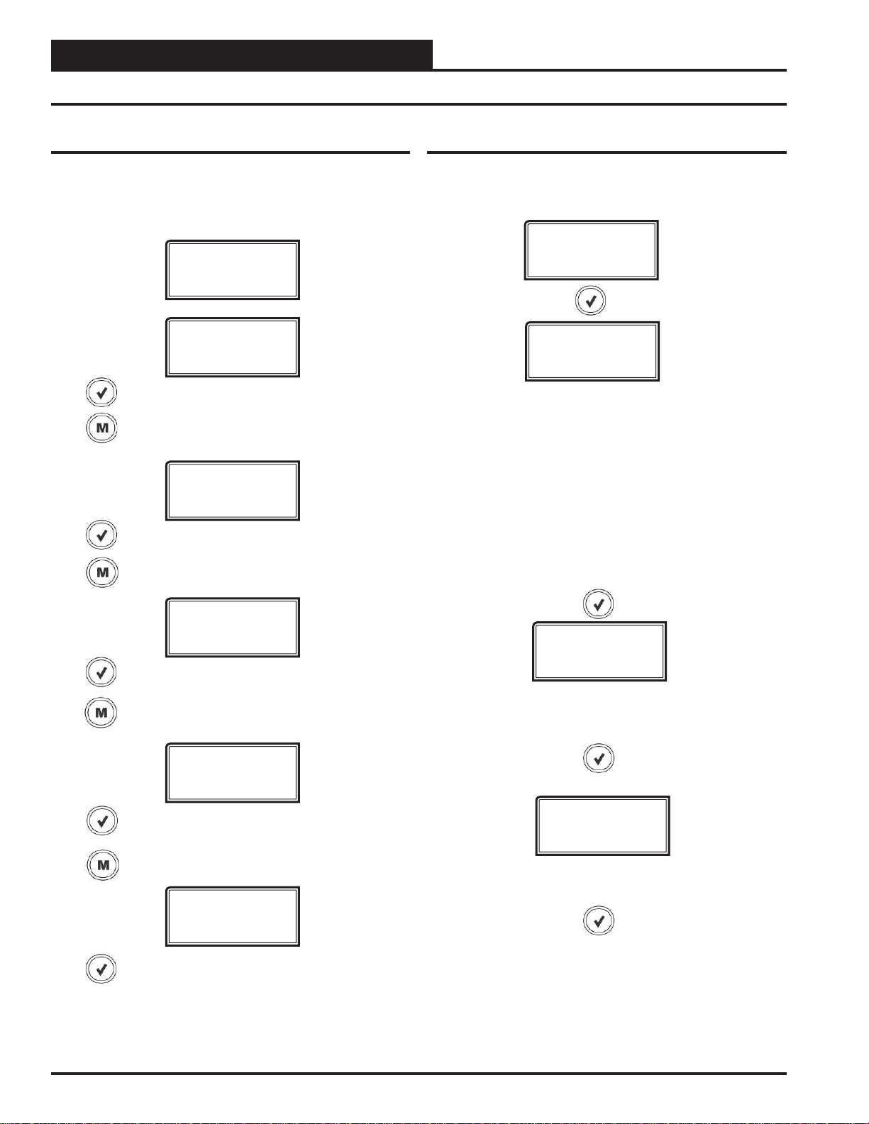
Main Screens Map
Refer to the following map when navigating through the LCD Main
Screens. The fi rst screen is an initialization screen. T o scroll through
the rest of the screens, press the
Press to scroll through MHG REHEAT Screens.
Press to go to STATUS Screens.
Press to scroll through STATUS Screens.
Press to go to ALARMS Screens.
<MENU> button.
INIT
VALVE
MHG
REHEAT
STATUS
SCREEN
Main MHG REHEAT Screens
Refer to the following map when navigating through the Main
Screens. From the MHG REHEAT Screen, press
scroll through the screens.
MHG
REHEAT
S/A MODE,
SA MODE LOCKED
or COMM MODE
In Stand-Alone Mode, the screen will display S/A MODE or S/A MODE
LOCKED.
In Communications Mode, the screen will display COMM MODE and the
items below will scroll through the screen:
1. Number of good packets being received. This will roll over after 9999.
Example: +XXXX
2. Number of checksum errors. This will stop at 9999. Example: C-XXXX
3. Number of packet length errors. This will stop at 9999 until power is
cycled. Example: P-XXXX
<ENTER> to
ALARMS
Press to scroll through ALARMS Screens.
Press to go to SETPOINTS Screens.
SETPOINTS
Press to scroll through SETPOINTS Screens.
Press to go to FORCE Screens.
FORCE
Press to scroll through FORCE Screens.
SOFTWARE
VER 1.04
CURRENT SOFTWARE VERSION
ADDRESS
#
CURRENT BOARD ADDRESS
10
MHGRV-X Field Technical Guide
Page 11

Status Screens
Refer to the following map when navigating through the Status
Screens. From the STATUS Screen, press
through the screens.
STATUS
Status Screens shown below will scroll automatically if LCD display is
left on this screen for 20 seconds.
MODE
OFF,REHEAT,
FLUSH,AUX,FORCE!
MODE
<ENTER> to scroll
LCD DISPLAY SCREENS
Status & Alarm Screens
ACTIV SP
XX.X
OR INACTIVE
ACTIVE SUPPLY AIR SETPOINT
Calculated from SAT setpoint and reset signal. Displays INACTIVE
when in OFF Mode or not needing to be calculated.
FLUSHTMR
COOLING,HEATING,
DISABLED
This screen displays the current mode of operation of the MHGRV-X
Controller. The mode options are:
OFF: This mode will display if the unit is not in Dehumidifi cation Mode
and there is no call for Modulating Hot Gas Reheat (MHGR).
REHEAT: During Dehumidifi cation, the unit will enter the Reheat Mode
and will begin to modulate the MHGR Valve to maintain the Supply Air
T emperature Setpoint. The unit will leave the Reheat Mode when the unit
leaves the Dehumidifi cation Mode.
FLUSH: This mode will display if the unit is performing a cooling fl ush
cycle or a reheat fl ush cycle (see Additional Features, page 8).
AUX: If Aux operation has been enabled, a 0-10 VDC signal can be
used to proportionally modulate the MHGR Valve between 0 – 100 %.
FORCE!: The unit is in the Force Mode.
VLV POS
100%
VALVE POSITION
0 to 100 percent
FLUSHTMR
XX
FLUSH
CYCLE ON
FLUSH TIMER AND FLUSH STATUS
Flush Timer screen will display if the unit is in Cooling Flush Mode, Heating Flush Mode, or Disabled. It will then display the time remaining in
minutes until the Flush Cycle begins. If the unit is in the Flush Cycle, it
will display FLUSH CYCLE ON.
Alarm Screens
Refer to the following map when viewing Alarm Screens. These
screens will display automatically when alarms are present. For
more information, see pages 13 & 14.
ALARMS
SA TEMP
XX.X
SUPPL Y AIR TEMPERA TURE
40ºF to 150ºF or 5ºC to 65ºC.
If no sensor is detected, screen will display “NO SENSR”
MHGRV-X Field Technical Guide
The alarms are as follows:
NO ALARMS: This will be shown if there are no current alarms.
SA T FAIL ERROR: The Supply Air Temperature sensor has been dis-
connected for more than 60 seconds. This alarm will be disabled when
the sensor is reconnected.
COMM T/O ERROR: Communications have been lost with the main
controller. This alarm will disable when communications resume.
11
Page 12

LCD DISPLAY SCREENS
Setpoint & Force Screens
Force Screens
Setpoint Screens
Refer to the following map when navigating through the Setpoint Screens. From the SETPOINTS Screen, press
to scroll through the screens and change setpoints. Use the <UP>
and <DOWN> arrow keys to change your selections. Then press
<ENTER> to save the new setpoint.
WARNING: When the MHGRV-X is operating in Comm-
nications Mode (connected to the Main Controller), these
setpoints screens will not appear on the LCD display because
they are controlled by the Main Controller. So, to get to these
Setpoints, you have to temporarily disconnect the MHGRV-X
from the Main Controller.
SETPOINTS
SAT SP
40-150°F
5-65°C
<ENTER>
Refer to the following map when navigating through the Force
Screens. From the FORCE Screen, press
<ENTER>. At the FORCE
MODE ON/OFF screen, press the <UP> arrow key to turn the
FORCE MODE on and press the <DOWN> arrow key to turn the
FORCE MODE off. Use the <UP> and <DOWN> arrow keys to
increase and decrease the percentage.
FORCE
FORCE
MODE ON/OFF
Press the <UP> button to turn the Force Mode on. Press the <DOWN>
button to turn the Force Mode off.
FRC VALV
X%
REHEAT SUPPLY AIR TEMPERATURE SETPOINT
This is the target temperature while reheat is enabled. If you are using
the reset signal, this is the setpoint it will calculate to at zero volts. Will
display only in stand-alone mode. The SAT Setpoint is set by the LCD
Display in stand-alone mode and is set by the Main Controller in communicating mode.
Minimum Default Maximum
40°F
5°C
70°F
21°C
150°F
65°C
RESET SP
40-150°F
5-65°C
RESET REHEAT SUPPLY AIR SETPOINT
This is maximum temperature at which the Supply Air Temperature will
reset to. Will display only in stand-alone mode.
The Reset SAT Setpoint is set by the LCD Display in stand-alone mode
and is set by the Main Controller in communicating mode.
Minimum Default Maximum
40°F
5°C
70°F
21°C
150°F
65°C
FORCE VALVE PERCENTAGE
This screen only appears when Force Mode is on.
Press the <UP> button to increase the percentage. Press the <DOWN>
button to decrease the percentage.
NOTE: When you turn the Force Mode back off or after 1 hour has
elapsed, the valve will reinitialize to zero.
FRC EXP
X%
FORCE EXPANSION VALVE PERCENTAGE
This screen only appears when Force Mode is on and Expansion Valves
are Enabled.
Press the <UP> button to increase the percentage. Press the <DOWN>
button to decrease the percentage.
NOTE: When you turn the Force Mode back off or after 1 hour has
elapsed, the valve will reinitialize to zero.
FORCE
TIMEOUT
FORCE MODE TIME OUT
This screen will appear when the Force Mode times out after 1 hour.
12
MHGRV-X Field Technical Guide
Page 13

TROUBLESHOOTING
Troubleshooting
LED Diagnostics
The MHGR V-X Controller is equipped with LEDs that can be used
to verify operation and perform troubleshooting. There are LEDs for
communication, operation modes, and diagnostic codes. The module
has 14 LEDs—12 used for operation & status, and 2 used for alarms.
See Figure 5 on page 14 for the LED locations. The LEDs associated with these inputs and outputs allow you to see what is active
without using a voltmeter. The LEDs and their uses are as follows:
Operation LEDs
POWER - This green LED will light up to indicate that 24 VAC
power has been applied to the controller.
STATUS - This green LED will light up and blink the board address
at startup. It will then blink according to what mode the controller is
in. See T able 3. Only the highest priority failure code will be shown.
You must correct the highest priority alarm before other problems
will be indicated.
No. of
Blinks
1 Off Mode
2 Reheat Mode
3 Flush Mode
4 Force Mode
5 SAT Sensor Failure Mode
STATUS LED
Relay LEDs
FAN - This green LED will light up to indicate that the relay for the
“F AN” output is energized and its Normally Open Contact is closed.
COMP - This green LED will light up to indicate that the relay for
the “COMP” output is energized and its Normally Open Contact
is closed.
VALVE - This green LED will light up to indicate that the relay for
the “VALVE” output is energized and its Normally Open Contact
is closed.
AUX - This green LED will light up to indicate that the relay for the
“AUX” output is energized and its Normally Open Contact is closed.
Binary Input LEDs
REHEA T ENABLE - This green LED will light up when the Reheat
is enabled.
HEA T OVERRIDE - This green LED will light up when Heat Over-
ride is enabled.
COOL OVERRIDE - This green LED will light up when Cool
Override is enabled.
Analog Output LEDs
CONDENSER V ALVE DRIVE - This LED is on any time the con-
denser valve is moving.
Table 3: STATUS LED Blink Codes
Diagnostic LEDs
ALARM - This red LED will light up to indicate an alarm. The type
of alarm will display on the LCD display. The ALARM LED also
blinks when the expansion valve is initializing at startup.
No. of
Blinks
1 Supply Air Temperature Sensor
Failure
2 Communications Time Out Error
ALARM LED
Table 4: ALARM LED Blink Codes
Communication LED
COMM - This yellow LED will light up and blink when communica-
tions are detected.
REHEA T V AL VE DRIVE - This LED is on any time the modulating
hot gas reheat valve is moving.
LED Troubleshooting
“POWER” LED: When the MHGRV-X Controller is powered up,
the POWER LED should light up and stay on continuously. If it does
not light up, check to be sure that the power wiring is connected to the
board, the connections are tight, and the transformer is powered. If after
making all these checks, the POWER LED does not light up, the board
is probably defective.
“STAT” LED:
powered up, the STAT LED will do the following:
As previously described, when the board is fi rst
On for 10 seconds
Blinks 30 times
Blinks 3 times rapidly (after STEP LED is on
for 45 seconds)
Status code is repeatedly blinked every ten seconds to
indicate controller status
MHGRV-X Field Technical Guide
13
Page 14

TROUBLESHOOTING
Troubleshooting
Alarm Troubleshooting
Supply Air Temperature Failure:
• Verify that the Supply Air Temperature Sensor is
connected to the SAT and GND on the MHGRV-X
or MODGAS Controller (stand-alone mode or when
using a CAV/VAV or MUA Controller) or to AI2
and GND on the Main Controller (communicating
mode).
• Remove SAT and GND wiring from MHGRV-X
and ohm sensor out (this may indicate open or
failed wiring). Refer to chart in back of this guide
for readings.
• Verify the SAT OPTIONS jumper settings on the
MHGRV-X for the Supply Air Temperature Sensor.
ALARM LED
Communications Loss:
• Check COMM LED on MHGRV-X.
• Verify 24 VAC power to all interconnected
WattMaster controllers.
• Verify E-BUS connection between the MHGRV-X
and associated WattMaster controllers.
• In communication mode (connected to an AAON
Unit
Controller’s MHGRV-X status screen displays
MHGRV-X’s Position % and that Main MHG Reheat
screens show COMM MODE.
MHGRV-X CONTROLLER
(OE377-26-00059)
Controller with modular cable), confi rm that
REHEAT ENABLE LED
HEAT OVERRIDE LED
COOL OVERRIDE LED
FAN RELAY LED
COMPRESSOR RELAY LED
VALVE RELAY LED
AUX RELAY LED
STATUS LED
ALARM LED
COMM LED
POWER LED
CONDENSER DRIVE
LED
REHEAT VALVE DRIVE
LED
Figure 5: MHGRV-X Controller LED Locations and Descriptions
14
MHGRV-X Field Technical Guide
Page 15

TROUBLESHOOTING
Troubleshooting
Other Checks
0-3V (SAT OPTIONS Jumper Settings Normal
And MODGAS-X) & 0-5V (SAT OPTIONS Jumper Setting MODGAS) Supply Air Temperature
Sensor
If you suspect the Supply Air Temperature Sensor is not reading
correctly, make sure the wiring terminal connections are tight and
that any wiring splices are properly connected. You can check the
operation of the Supply Air Temperature Sensor by measuring the
resistance or voltage using a digital multimeter. Set the meter to DC
Volts. Place the positive probe on the AIN terminal and the negative
probe on the GND terminal. Read the DC Volts and fi nd that voltage
in Tables 5 & 6.
Read the temperature corresponding with that voltage and determine
if this is close to the actual temperature the sensor is exposed to. If the
temperature from the chart is different by more than a few degrees,
you probably have a defective or damaged sensor. You can also
check the sensor resistance to determine correct operation. To read
the resistance, set the meter to Ohms. Unplug the sensor connector
from the board and measure the resistance across the disconnected
wires. This resistance should match the corresponding temperature
from Tables 5 & 6.
Temperature to Resistance/Voltage Chart
Temp
(°F)
-10 -23.3 93333 2.98
-5 -20.6 80531 2.94
0 -17.8 69822 2.89
5 -15.0 60552 2.83
10 -12.2 52500 2.77
15 -9.4 45902 2.71
20 -6.7 40147 2.64
25 -3.9 35165 2.57
30 -1.1 30805 2.49
35 1.6 27140 2.41
40 4.4 23874 2.33
45 7.2 21094 2.24
50 10.0 18655 2.15
52 11.1 17799 2.11
54 12.2 16956 2.08
56 13.3 16164 2.04
58 14.4 15385 2.00
60 15.6 14681 1.96
Table 5: 0-3V Temperature Sensor - Voltage &
Resistance for Type III Sensors
Temp
(°C)
Resistance
(Ohms)
Voltage @
Input (VDC)
Temperature to Resistance/Voltage Chart
Temp
(°F)
62 16.7 14014 1.93
64 17.8 13382 1.89
66 18.9 12758 1.85
68 20.0 12191 1.81
69 20.6 11906 1.79
70 21.1 11652 1.78
71 21.7 11379 1.76
72 22.2 11136 1.74
73 22.7 10878 1.72
74 23.3 10625 1.70
75 23.9 10398 1.68
76 24.4 10158 1.66
78 25.6 9711 1.63
80 27.8 9302 1.59
82 27.8 8893 1.55
84 28.9 8514 1.52
86 30.0 8153 1.48
88 31.1 7805 1.45
90 32.2 7472 1.41
95 35.0 6716 1.33
100 37.8 6047 1.24
105 40.6 5453 1.16
110 43.3 4923 1.09
115 46.1 4449 1.02
120 48.9 4030 .95
125 51.7 3656 .88
130 54.4 3317 .82
135 57.2 3015 .76
140 60.0 2743 .71
145 62.8 2502 .66
150 65.6 2288 .61
Temp
(°C)
Resistance
(Ohms)
Voltage @
Input (VDC)
Table 5, continued: 0-3V Temperature Sensor Voltage & Resistance for Type III Sensors
Thermistor Sensor Testing Instructions
1.) Use the resistance column to check the thermistor sensor while
disconnected from the controllers (not powered).
2.) Use the voltage column to check sensors while connected to
powered controllers. Read voltage with meter set on DC volts. Place
the “-” (minus) lead on GND terminal and the “+” (plus) lead on the
sensor input terminal being investigated.
If the voltage is above 3.3 VDC, the sensor or wiring is “open.” If
the voltage is less than 0.05 VDC, the sensor or wiring is shorted.
MHGRV-X Field Technical Guide
15
Page 16

TROUBLESHOOTING
Troubleshooting
Temperature to Resistance/Voltage Chart
Temp
(°F)
-10 -23.3 93333 4.620
-5 -20.6 80531 4.550
0 -17.8 69822 4.474
5 -15.0 60552 4.390
10 -12.2 52500 4.297
15 -9.4 45902 4.200
20 -6.7 40147 4.095
25 -3.9 35165 3.982
30 -1.1 30805 3.862
35 1.6 27140 3.737
40 4.4 23874 3.605
45 7.2 21094 3.470
50 10.0 18655 3.330
52 11.1 17799 3.275
54 12.2 16956 3.217
56 13.3 16164 3.160
58 14.4 15385 3.100
60 15.6 14681 3.042
62 16.7 14014 2.985
64 17.8 13382 2.927
66 18.9 12758 2.867
68 20.0 12191 2.810
69 20.6 11906 2.780
70 21.1 11652 2.752
71 21.7 11379 2.722
72 22.2 11136 2.695
73 22.7 10878 2.665
74 23.3 10625 2.635
75 23.9 10398 2.607
76 24.4 10158 2.577
78 25.6 9711 2.520
80 27.8 9302 2.465
82 27.8 8893 2.407
84 28.9 8514 2.352
86 30.0 8153 2.297
88 31.1 7805 2.242
90 32.2 7472 2.187
95 35.0 6716 2.055
Temp
(°C)
Resistance (Ohms) Voltage @
Input (VDC)
Temperature to Resistance/Voltage Chart
Temp
(°F)
100 37.8 6047 1.927
105 40.6 5453 1.805
110 43.3 4923 1.687
115 46.1 4449 1.575
120 48.9 4030 1.469
125 51.7 3656 1.369
130 54.4 3317 1.274
135 57.2 3015 1.185
140 60.0 2743 1.101
145 62.8 2502 1.024
150 65.6 2288 0.952
Temp
(°C)
Resistance (Ohms) Voltage @
Input (VDC)
Table 6, cont.: 0-5V Temperature Sensor - Voltage
& Resistance for Type III Sensors
Thermistor Sensor Testing Instructions
1.) Use the resistance column to check the thermistor sensor while
disconnected from the controllers (not powered).
2.) Use the voltage column to check sensors while connected to
powered controllers. Read voltage with meter set on DC volts. Place
the “-” (minus) lead on GND terminal and the “+” (plus) lead on the
sensor input terminal being investigated.
If the voltage is above 5.08 VDC, the sensor or wiring is “open.” If
the voltage is less than 0.05 VDC, the sensor or wiring is shorted.
Table 6: 0-5V Temperature Sensor - Voltage &
Resistance for Type III Sensors
16
MHGRV-X Field Technical Guide
Page 17

APPENDIX A
Supply Air Temperature Sensor Installation
Mounting the Supply Air Temperature
Sensor
The Supply Air Temperature Sensor should be located in the ductwork downstream of the unit supply air connection. Locate the sensor
in the center of the widest part of the duct. Use the supplied template
and a 5/16” drill to make a hole for the sensor. Install the gasket
over the probe and mount securely to the duct using the supplied
sheet metal screws. Be sure the gasket is compressed to provide an
air tight seal. For best accuracy, apply insulation on the outside of
the duct, over the sensor. This will help prevent thermal gradients
from affecting the sensor.
WARNING: Make sure your Supply Air Temperature Sensor
is mounted and wired according to these
instructions prior to testing the unit or else the
modulating valve will not control properly and
may damage your equipment.
Leads Are Non-Polarized. Butt Splice Leads
To 24 Gauge Wire Minimum.
In Stand Alone Applications And In Retrofit Applications,
Connect Leads to “SAT” And “GND” On MHGRV-X Controller
See .
Table 7, Page 18
Stand-Alone Mode
In Stand-Alone Mode, the SA T Sensor is connected to the MHGRVX Controller. If, in Stand-Alone Mode, the MHGRV-X Controller
is used in conjunction with a Stand-Alone MODGAS-X Controller,
the SAT sensor is shared between the two controllers and always
attaches to the MODGAS-X Controller.
See Table 8 on page 18 for SAT Options Jumper Settings and see
Figure 3 on page 6 for wiring.
Communication Mode
When communicating with AAON Unit Controllers, the SAT Sensor
will be connected to the Main Controller. The exception would be
in retrofi t applications with older controllers. See Table 9 on page
18 for SAT Options Jumper Settings and see Figures 2 on page 5
for wiring. See Table 7 on page 18 and Appendix B on page 19
for details about retrofi t applications.
If Using VCM, VCM-X, SA, RNE Or VCB-X
Controller, Connect Leads To “AI2” And “GND”
On Main Controller.
Figure 6: Supply Air Temperature Sensor Installation
MHGRV-X Field Technical Guide
17
Page 18

APPENDIX A
SAT Sensor Wiring Guide & Jumper Settings
SAT Wiring Conditions
MODGAS-X ONLY MHGRV-X ONLY MODGAS-X & MHGRV-X
STAND-
ALONE
VCB-X Install Supply Air Sensor
VCM-X,
SA, RNE
VCM,
VAV/CAV,
MUA,
MUA II,
MUA IID
Install Supply Air
Sensor in MODGAS-X.
in VCB-X.
Connect to VCB-X
using E-BUS cable.
Install Supply Air Sensor
in Main Controller.
Connect to Main
Controller using I
cable.
Install Supply Air Sensor
in MODGAS-X.
Connect to Main
Controller using I
cable.
2
C
2
C
Install Supply Air
Sensor in MHGRV-X.
Set “SAT Options”
Jumpers to “Normal”.
Install Supply Air
Sensor in VCB-X.
Connect to VCB-X
using E-BUS cable.
Install Supply Air
Sensor in Main Controller.
Connect to Main
Controller using I2C cable.
Install Supply Air
Sensor in MHGRV-X.
Connect to Main
Controller using I2C cable.
Table 7: SAT Wiring Conditions
SAT Options Jumper Settings
Refer to T ables 8 & 9 to determine the SAT Option Jumper settings.
See Figures 2 & 3 on pages 5 & 6 for jumper locations.
Install Sensor in MODGAS-X and daisy-chain it
to the MHGRV-X. Set “SAT Options” Jumpers to
“MODGAS X”. If connected to a MODGAS II
Retrofi t, Set “SAT Options” Jumpers to “MODGAS”.
Install Supply Air Sensor in VCB-X.
Connect to VCB-X using E-BUS cable.
Install Supply Air Sensor in Main Controller.
Connect to Main Controller using I
Install Supply Air Sensor in MODGAS-X.
Connect to Main Controller using I
COMMUNICATIONS MODE
SAT OPTIONS JUMPER SETTINGS*
CONDITION SETTING
2
C cable.
2
C cable.
STAND-ALONE MODE
SAT OPTIONS JUMPER SETTINGS*
CONDITION SETTING
MHGRV-X Only Normal
MHGRV-X with
MODGAS-X** MODGAS-X
MHGRV-X with
MODGAS II*** MODGAS
* For SAT Sensor testing, use Table 7 for
Normal & MODGAS-X jumper setting and use
Table 8 for MODGAS jumper setting.
** In this situation, also set MODGAS-X SAT
Option to Jumper Setting 1. See the MODGAS-X
Technical Guide for more information.
*** The MODGAS II must have PU1 resistor
installed.
Table 8: Stand Alone Mode SAT OPTIONS Jumper
Settings
18
VCM / VCM-X / SA/ RNE * Normal
MUA, VAV/CAV** Normal
VCB-X* Normal
* For SAT Sensor testing, use Table 7 for Normal
jumper setting. SAT should be connected to the
Main Controller.
** For SAT Sensor testing, use Table 7 for Normal
jumper setting. SAT should be connected to the
MHGRV-X Controller.
Table 9: Communications Mode SAT OPTIONS
Jumper Settings
MHGRV-X Field Technical Guide
Page 19

APPENDIX B
Appendix B - MHGRV-X Replacement of MHGRV II
Replacing the MHGRV II with the
MHGRV-X
The drop-in replacement involves a few easy steps. Refer to Figure 7.
STAND-ALONE MODE OPERATION
Step 1: Disconnect power from the MHGRV II Controller.
Step 2: Disconnect the Supply Air Temperature Sensor from the
MHGRV II and wire it to the MHGRV-X. If the Supply
Air Temperature Sensor is being shared with a Stand Alone MODGAS Controller, maintain the same wiring
with the MODGAS Controller.
Step 3: Separate the HGR Valve wires and the Condenser Valve
wires onto the appropriate Reheat Drive and Condenser
Drive terminal blocks per Figure 3, page 6. Wire all
other inputs and outputs per Figure 3, also.
Step 4: Set the SAT Options Jumper per Table 8, page 18.
Step 5: Connect power to the MHGRV-X Controller.
COMMUNICATIONS MODE OPERATION
Step 1: Disconnect power from the MHGRV-II Controller.
Step 2: The Supply Air Temperature Sensor needs to remain
installed on whatever controller it is currently on. If it
is currently installed on the MHGRV II Controller, then
reinstall it on the MHGRV-X Controller. If it is currently
installed on the main unit controller or on a connected
MODGAS Controller, it needs to remain there.
Step 3:
Set the SAT Options Jumper per Table 9, page 18.
Step 4: Connect power to the MHGRV-X Controller.
MHGRV-X CONTROLLER
(OE377-26-00059)
Connect To MHGRV-X Controller
In Stand-Alone Mode Or When
Using VAV/CAV Or MUA Controller.
If Also Using A MODGAS Controller
In Stand Alone Mode,
The SAT Sensor Connects
To The MODGAS Controller.
Supply
Air Temperature
Sensor
Mount In Supply
Air Duct
See Tables 7, 8 & 9 On Page 18 For
SAT OPTIONS Jumper Settings.
Only One Supply Air Temperature Sensor
Can Be Used Per Application.
2
I C Cable
Connects To
AAON Unit Controller’s
Port
1.)24 VAC Must Be Connected So
That All Ground Wires Remain
Common.
2.)All Wiring To Be In Accordance
With Local And National
Electrical Codes And
Specifications.
GND
24VAC
40 VA
Transformer
Minimum
Figure 7: MHGRV-X Controller
MHGRV-X Field Technical Guide
Line
19
Page 20

APPENDIX C - REHEAT EXPANSION MODULE
Features & Dimensions
Overview
The OE377-01-00059 Reheat Expansion Module (AAON Part No.
V42450) is designed to control one set of reheat valves.
The Reheat Expansion Module connects to the MHGR V -X Controller
via an EBC E-BUS communication cable.
Connected together, the Reheat Expansion Modules provide a system
that allows the proper control of multiple sets of valves.
See Figure 8 for dimensions (in inches).
2.10
1.551.05
Features
The Reheat Expansion Module provides the following:
Up to (7) Reheat Expansion Modules can be used
Each Reheat Expansion Module controls one set of
reheat valves (1 Reheat & 1 Condenser)
Each Reheat Expansion Module has its own Cooling &
Reheat Flush Timers
Reheat Expansion Modules conveniently plug
into one another
2.75
2.13
Ø.200
4.23
(2) Chevron Cut Snap Tracks
(BK000085)
2.075
2.075
4.15
24VAC
CONTROLS INC
WATTMASTER
YS102608 R0
2013
COMM
STATUS
RED/GRN
GRN/RED
BLACK
WHITE
COMM
GND
4.15
GND
ENABLE
COND/REHEAT
Reheat Expansion Module
(OE377-01-00059)
Figure 8: OE377-01-00059 Reheat Expansion Module and Mounting Plate Dimensions
20
MHGRV-X Field Technical Guide
Page 21

APPENDIX C - REHEAT EXPANSION MODULE
Installation & Wiring
Installation & Mounting
The Reheat Expansion Module is provided with a Chevron cut
plastic snap track mounting base. The snap track is designed to be
mounted using a ¼” Hex Head Sheet Metal Screw (provided) to a
fl at surface using the pre-punched mounting hole that is provided
in the center of the snap track. The Reheat Expansion Module is
then snapped into place on the snap track, providing for easy fi eld
mounting and servicing.
The Reheat Expansion Module needs to be installed in an environment which can maintain a temperature range between -30°F
and 150°F not to exceed 90% RH levels (Non-Condensing). It is
important to keep the module in a location that is free from extreme
high or low temperatures, moisture, dust, and dirt. Be careful not to
damage the electronic components.
NOTE: The Reheat Expansion Module contain no user-
serviceable parts. Contact qualified technical
personnel if your Controller or Module is not operating correctly.
General Wiring Information
For the wiring diagram to use when the MHGRV-X Controller is
connected to an AAON Unit Controller, see Figure 2, page 5. For
the stand-alone wiring diagram, see Figure 3, page 6.
For Reheat Expansion Board wiring, see Figure 9, page 22.
Please carefully read and apply the following information when
wiring the Reheat Expansion Module(s):
1. 18 gauge minimum wire unless otherwise noted.
24 VAC power connection with an appropriate VA rating.
2.
3. Compressor Enable must have 24 gauge minimum wire.
4. All 24 VAC wiring must be connected so that all ground
wires remain common. Failure to follow this procedure can
result in damage to the module and connected devices.
5. All wiring is to be in accordance with local and
national electrical codes and specifi cations.
6. Check all wiring leads at the terminal block for tightness.
Be sure that wire strands do not stick out and touch
adjacent terminals. Confi rm that all transducers required for
your system are mounted in the appropriate location and
wired into the correct terminals.
MHGRV-X Field Technical Guide
21
Page 22

APPENDIX C - REHEAT EXPANSION MODULE
Wiring
Reheat Expansion Module(s) Wiring
Reheat Expansion Modules snap into each other at the power and
Comm connectors. Up to (7) Reheat Expansion Modules can be used.
Apply power to the fi rst Reheat Expansion Module in a series. The
last Reheat Expansion Module in a series connects to the MHGR V -X
Controller using an EBC E-BUS cable.
See Figure 9 below for details.
OE377-01-00059
Reheat Expansion Module
(2)
Shown Connected Together
Up to (7) Expansion Modules Can Be Connected
Line
24VAC
24VAC
24VAC
12 VA
Transformer
Minimum
GND
GND
2013
WATTMASTER
CONTROLS INC
YS102608 R0
GND
2013
WATTMASTER
CONTROLS INC
YS102608 R0
Compressor #2
Enable Relay
STATUS
COMM
STATUS
COMM
GND
GND
C2
ENABLE
COND/REHEAT
BLACK
WHITE
RED/GRN
GRN/RED
ENABLE
COND/REHEAT
BLACK
WHITE
RED/GRN
GRN/RED
Comm
Connector
COMM
COMM
Compressor #3
C3
Comm
Connector
HGR Valve #1
BLK
WHT
GRN
RED
Condenser Valve #1
BLK
WHT
RED
GRN
Enable Relay
HGR Valve #2
BLK
WHT
GRN
RED
Condenser Valve #2
BLK
WHT
RED
GRN
Power
Connector
Chevron Cut
Snap Track
Figure 9: Reheat Expansion Module(s) Wiring
22
EBC E-BUS
Cable
Last Reheat
Expansion Module
In A Series
Connects To
MHGRV-X
Controller
NOTE:
1.) Connect The Next Reheat
Expansion Module To The
Power Connector And Comm
Connector Of The Previous
Reheat Expansion Module In
A Series. Up to (7) Expansion
Modules Can Be Connected.
MHGRV-X Field Technical Guide
Page 23

APPENDIX C - REHEAT EXPANSION MODULE
Operation Modes
Initialization
The Reheat Expansion Module uses on-board LEDs to indicate various diagnostic conditions during power-up and operation. See the
LED Operation section on page 21 for more information.
Modulating Hot Gas Valves
Each Reheat Expansion Module utilizes two modulating valves to
control the fl ow of Hot Gas through the Hot Gas Reheat Coil. One
of these valves is the Condenser Hot Gas Valve and the other is the
Reheat Hot Gas Valve. The valves are wired to the Reheat Expansion Module’s Modulating Hot Gas Valve Output terminals. These
valves work in concert with each other to create a “three-way valve”
confi guration. As one closes, the other opens, etc. All modes of opera-
tion that follow referring to the Hot Gas Reheat Valve are actually
a combination of these two valves working together to achieve the
specifi ed sequence of operation.
Mode of Operation
The Reheat Expansion Module(s) can be used in MHGRV-X stand
alone operation and when the MHGRV-X is communicating to an
AAON Unit Controller.
Stand-Alone Operation
See page 8 for MHGRV-X stand-alone operation. Once the Reheat
Expansion Module’s Binary Input Compressor input is enabled, the
valve positions follow the MHGRV-X Controller.
Additional Features
Reheat Coil Flush
To assure positive oil return to the compressor, the Hot Gas Reheat
Coil will be fl ushed of liquid refrigerant by moving the Modulat-
ing Gas Reheat Valve to its maximum position for a short interval.
Cooling Flush: If the unit is in cooling mode, a fl ush will occur
when the unit’s fl ush cooling interval timer has elapsed. The time
is accumulated whenever it is in cooling mode and resets after each
fl ush cycle. The fl ush cooling interval timer is a setpoint that is
confi gurable using the keypad and display (0 to 120 minutes in 10
minute increments). If enabled, each Reheat Expansion Module follows the same sequence as the MHGRV -X, using the same cooling
fl ush interval timer of the MHGRV-X. The expansion boards do not
fl ush at the same time.
Reheat Mode Flush: If the unit is in dehumidifi cation mode and
the valve is below 70% for the fl ush reheat interval timer value, a
fl ush will occur. If the valve goes above 70%, the timer is reset. The
fl ush reheat interval timer is a setpoint that is confi gurable using the
keypad and display (0 to 120 minutes in 10 minute increments). If
enabled, each Reheat Expansion Module follows the same sequence
as the MHGRV -X, using the same fl ush reheat interval timer of the
MHGRV-X. The expansion boards do not fl ush at the same time.
Operation in Communicating Mode
In this mode, the MHGRV-X Controller behaves as an expansion
board for an AAON Unit controller. See page 8 for detailed operation. Once the Reheat Expansion Module’s Binary Input Compressor input is enabled, the valve positions follow the MHGRV-X
Controller.
MHGRV-X Field Technical Guide
23
Page 24

APPENDIX C - REHEAT EXPANSION MODULE
LED Diagnostics & Troubleshooting
LED Diagnostics
The Reheat Expansion Module is equipped with 4 LEDs that can be
used to verify operation and perform troubleshooting.
See Figure 10 below for the LED locations. The LEDs associated
with these inputs and outputs allow you to see what is active without
using a voltmeter. The LEDs and their uses are as follows:
Operation LEDs
POWER - This green LED will light up to indicate that 24 VAC
power has been applied to the Expansion Module.
STATUS - This green LED will light up and blink every 10 seconds
according to valve position. One blink per 10%. Example: valve
position is 67%. STATUS LED will blink 6 times every 10 second
cycle. The ST ATUS LED will stay on solid during the 2 minute fl ush
cycle. See Table 10 below.
No. of
Blinks
1 - 10 Per 10% Valve Position
SOLID During 2 Minute Flush Cycle
Table 10: STATUS LED Blink Codes
STATUS LED
Communication LED
COMM - This amber LED will light up and blink once for every
good packet received. Packets should be sent once every second,
so Comm LED should blink the same, once every second. COMM
LED should blink simultaneously on all modules.
Binary Input LED
COMPRESSOR ENABLE - This green LED will light up when
the Reheat is enabled.
LED Troubleshooting
“POWER” LED: When the Reheat Expansion Module is powered up,
the POWER LED should light up and stay on continuously. If it does
not light up, check to be sure that the power wiring is connected to the
board, the connections are tight, and the transformer is powered. If after
making all these checks, the POWER LED does not light up, the board
is probably defective.
“ST AT” LED:
When the board is fi rst powered up, the STAT LED
will do the following:
On for 10 seconds
Blinks 30 times
Status code is repeatedly blinked every ten seconds to
indicate valve position
POWER
LED
24VAC
GND
2013
WATTMASTER
CONTROLS INC
YS102608 R0
STATUS LED
COMM LED
Figure 10: Reheat Expansion Module(s) Wiring
COMPRESSOR
ENABLE
LED
STATUS
COMM
STATUS
COMM
GND
ENABLE
COND/REHEAT
BLACK
WHITE
RED/GRN
GRN/RED
COMM
24
MHGRV-X Field Technical Guide
Page 25

APPENDIX C - REHEAT EXPANSION MODULE
Troubleshooting
Q & A
The following are common questions and their answers:
Q: Is there power to the expansion module?
A:
The POWER LED should be lit at all times. If not, check the
24VAC input voltage. If the input voltage is confi rmed and the
POWER LED is not lit, the board is physically damaged.
Q: Is the expansion module communicating?
A: You should always see the COMM LED(s) blinking
simultaneously on all modules. The communication chain is
physically connected from board to board; however, the
communications circuit is a parallel connection so it is
possible one module could be inoperable while others down
the chain are operating.
A: If you see the COMM LED on solid, then the module has not
detected communications for over 60 seconds.
Q: Is the valve position correct?
A: The STATUS LED will blink the valve position every 10
seconds if the valve is not closed. It will blink the position
divided by 10. So, for example, if the position is 68%, the
STATUS LED will blink 6 times.
A: The valve position displayed on the MHGRV-X Status Screen
should match the expansion module’s valve position. The
expansion module must have the enable signal activated for
the valve position to mirror the MHGRV-X.
Q: The STATUS LED is on solid. What does this mean?
A: The expansion module is performing its own fl ush cycle.
Each expansion module tracks its own fl ush cycles.
The fl ush time setpoints are always the same as the
MHGRV-X setpoints.
Q: I have no Communications. Can my valve still drive?
A:
If the enable signal is activated, it will still perform cooling
fl ush cycles.
Q: How can I test if the expansion module will drive the
valve?
From the MHGRV-X, you can go to the Force Menu and
A:
manually drive the expansion module valves open and closed.
Q: Are my valves wired correctly?
A:
Both valves per circuit should be wired to the same terminal
block.
A: The Condenser Valve should be wired (from top to bottom)
BLACK, WHITE, RED, GREEN
A: The Reheat Valve should be wire (from top to bottom)
BLACK, WHITE, GREEN, RED
Q: How do I confi rm the expansion module is operating in
Reheat (Dehumidifi cation) mode?
Make sure the enable signal is activated by confi rming that the
A:
ENABLE LED is on.
A: Make sure the COMM LED is blinking.
A: Compare the Valve Position displayed on the MHGRV-X
screen with the number of STATUS LED blinks.
A: If all three things above are true, then the valve is operating
correctly in Reheat mode.
Q: Are the communications wired and confi gured
correctly?
A: For the MHGRV-X operating as stand-alone, the
following should be true:
1. The MHGRV-X is connected to the Reheat Expansion
Module with an E-BUS cable and the connections are
secure.
2. The MHGRV-X must be confi gured as S/A LOCKED in
the MHGRV-X Confi guration Screens. To confi rm this,
press the ENTER key once from the main screen. It should
display S/A MODE LOCKED.
3. The MHGRV-X must be confi gured for EXP VLVS
ENABLED in the MHGRV-X Confi guration Screens. If
this is true, the COMM LED on the MHGRV-X will blink
once every second.
A: For the MHGRV-X operating with a VCB-X, the
following should be true:
1. The VCB-X, MHGRV-X, and Reheat Expansion Module
are connected to each other with an E-BUS cable and the
connections are secure.
2. The MHGRV-X must be confi gured as S/A AUTODECT in
the MHGRV-X Confi guration Screens.. To confi rm this,
press the ENTER key once from the main screen. It should
display COMM MODE .
3. The MHGRV-X must be confi gured for EXP VLVS
ENABLED in the MHGRV-X Confi guration Screens. If
this is true, the COMM LED on the MHGRV-X will blink
once every second.
Q: How do I change confi gurations for the valve
expansion modules?
Confi gurations will always match how the MHGRV-X is
A:
confi gured. The confi gurations are as follows:
1. Valve Size (hidden screen confi guration)
2. Cooling Flush Time (setpoint screens when stand-alone)
3. Reheat Flush Time (setpoint screens when stand-alone)
4. Reheat Flush Reset Position (cannot be changed by user)
MHGRV-X Field Technical Guide
25
Page 26

2425 So. Yukon Ave • Tulsa, OK • 74107-2728
Ph: (918) 583-2266 • Fax: (918) 583-6094
AAON® Part No.: V16950
WM Form: AA-MHGRVX-FIELD-TGD-01H
Printed in the USA • Copyright April 2015 • All Rights Reserved
WattMaster Controls, Inc. • 8500 NW River Park Drive • Parkville, MO • 64152
 Loading...