

Page 1
MHGRV III Controller
Technical Guide
Page 2

Table of Contents
Controller Overview ......................................................................................................................................... 3
General.........................................................................................................................................................................................3
Features .......................................................................................................................................................................................3
Operation......................................................................................................................................................................................3
Inputs and Outputs .......................................................................................................................................... 4
General.........................................................................................................................................................................................4
Analog Inputs ............................................................................................................................................................................... 4
24 VAC Contact Closure Inputs ....................................................................................................................................................4
Analog Outputs.............................................................................................................................................................................4
Relay Outputs...............................................................................................................................................................................4
Modulating HGR Valve Outputs ...................................................................................................................................................4
Installation & Wiring ........................................................................................................................................ 5
Controller Mounting ...................................................................................................................................................................... 5
Important Wiring Considerations .................................................................................................................................................. 5
Additional Modulating Hot Gas Valve Control ..............................................................................................................................5
MGHRV III Controller Master To Slave Wiring when Used with VCM Controller .........................................................................6
MGHRV III Controller Master To Slave Wiring when Used with VCM-X Controller ...................................................................... 8
MGHRV III Controller Master To Slave Stand Alone Wiring .......................................................................................................10
DIP Switch Settings ....................................................................................................................................... 12
Supply Air Temperature .............................................................................................................................................................. 12
Supply Air Temperature Reset Limit ..........................................................................................................................................12
Field Testing ...............................................................................................................................................................................13
Start-up & Commissioning............................................................................................................................. 14
General.......................................................................................................................................................................................14
Power Wiring ............................................................................................................................................................................. 14
Power Up and Operation ............................................................................................................................................................14
Programming the Controller .......................................................................................................................................................14
Sequence of Operation .................................................................................................................................. 15
Initialization.................................................................................................................................................................................15
Modulating Hot Gas Valves ........................................................................................................................................................15
Modes of Operation ....................................................................................................................................................................15
Additional Features .................................................................................................................................................................... 15
Troubleshooting ............................................................................................................................................. 16
Using LEDs to Verify Operation..................................................................................................................................................16
Other Checks ............................................................................................................................................................................. 16
2425 So. Yukon Ave • Tulsa, OK • 74107-2728
Ph: (918) 583-2266 • Fax: (918) 583-6094
WM Form: AA-MHGRVIII-TGD-01D
Printed in the USA • Copyright 2010 • All Rights Reserved • March 2011Watt-
Master Controls, Inc. • 8500 NW River Park Drive • Parkville, MO 64152
AAON® Part No.: R76540
WattMaster Controls, Inc. assumes no responsibility for errors or omissions.
AAON® is a registered trademark of AAON, Inc., Tulsa, OK.
This document is subject to change without notice.
Page 3
MHGRV III Controller Technical Guide
Controller Overview
General
The MHGRV III Controller is designed to control a Modulating Hot
Gas Reheat Valve to maintain a desired Supply Air Temperature and
Humidifi cation setpoint. The controller can be used as a stand-alone con-
troller or it can be connected to and used in conjunction with the AAON
Factory Packaged HVAC unit controller. The MHGRV III controller is
connected to the HVAC unit controller via a modular expansion cable
and corresponding connectors on the controllers.
Features
The MHGRV III provides the following:
Can be operated as a stand-alone controller or
integrated with the HVAC Unit Controller
Provides for Supply Air Temperature Setpoint
reset when required
Second stage reheat capability when using
2 Hot Gas Reheat Valves
Control of reheat solenoid valve to provide coil
fl ushing for positive refrigerant oil return
Expansion capabilities for controlling additional
modulating hotgas values
Operation
When used in a stand-alone application (not connected to an HVAC unit
controller board), the MHGRV III controller will control the Modulating
Hot Gas Valve to maintain the Supply Air Setpoint based on the Supply
Air Temperature Sensor connected to the MHGRV III controller. The
MHGRV III controller is activated by a 24 VAC wet contact closure
signal connected to the H1 (RHT EN) input terminal on the controller.
Heating Override and Cooling Override are also controlled by 24 VAC
wet contact closure signals connected to the HEAT OVR and COOL
OVR input terminals on the controller. The Supply Air Setpoint is set
by confi guring a DIP switch on the MHGRV III controller board. Sup-
ply Air Temperature Reset is also available and is set by confi guring
a DIP switch on the controller board. When Supply Air Temperature
Reset is used, it is reset by a 0-10 VDC signal supplied to the RESET
IN terminal on the MHGRV III controller.
When the MHGRV III controller is connected to an HVAC unit controller board via its modular cable, it will operate exactly as the stand-alone
controller except that the following information will be passed between
the MHGRV III controller and the HVAC unit controller:
Reheat Enable command
Supply Air Temperature Setpoint. This replaces the
setpoint that is set with the Supply Air Temperature DIP
switch on the MHGRV III controller.
The Reset Supply Air Temperature Setpoint. This replaces
the setpoint that is set with the Supply Air Temperature
Reset DIP switch on the MHGRV III controller. The Supply
Air Temperature Reset Signal is also supplied from the
HVAC unit controller.
If the communication is interrupted between the MHGRV
III controller and the HVAC unit controller, the
MHGRV III controller will revert to stand-alone operation.
0.30
7.40
1248163264
1002
R45
1
ADD ADD
1002
R28
P4
CHASSISGND
C16
128
OFF
1002
1002
1002
1002
1002
1002
1002
R52
R51
R50
R49
R48
R47
R46
128643216842
OFF
1002
1002
1002
1002
1002
1002
1002
R34
R33
R32
R31
R35
R30
R29
2211
2211
2211
2211
R44R43
R42R41
R57R56
R55R54
2211
2211
2211
2211
COM
AUX
D11
VALVE
CMP
D8
FAN
D7
TB2
.1uF
C31
R73
R72
LM358
1001
1001
TB6
1002
10uF
.01uF
GND
AOUT
C33
C18
.1uF
U14
74HC541
SW2
C21
.1uF
U13
74HC541
RESET LIMIT SETPOINT
SW1
TPIC6B259
.1uF
C13
U11
10A250VAC~
5A30VDC
V4
VDE
SA
10A250VAC~
5A30VDC
V3
VDE
SA
10A250VAC~
5A30VDC
V2
VDE
SA
10A250VAC~
5A30VDC
V1
VDE
SA
C3
.1uF
C6
.1uF
SF000140
U19
R69
R78
1002
U12
R76
4751
R77
4751
R74
4751
0404
R75
4751
U20
.1uF
CHINA
DC24V
G5Q-1A4
OMRON
K4
CHINA
L293DNE
NE5090
DC24V
G5Q-1A4
OMRON
K3
CHINA
C24
.1uF
DC24V
G5Q-1A4
OMRON
K2
CG/HR
CR/HG
CHINA
DC24V
G5Q-1A4
OMRON
K1
U8
C2
.1uF
C36
.1uF
CY62256LL
74HC573
U4
U2
EPROM
R60
R62
36503650
D13
D12
STATSTEP
J2
10uF
0-5V
C25
U16
1002
0-10V
1002
4-20
2500
THERM
1002
R53
AUXIN
VAVLE EXP
TB4
GND
GND
+VDC
CW/HW
CB/HB
SF000093a
U15
X2VR1
C22
C26
R59
R38
R58
4751
R61
R37
3001
R36
4751
R27
3001
R26
4751
D10
3001
R25
R40
R39
10uF
C20
1002
1002
AUX IN
RHT EN
RESET IN
.1uF
C23
VREF
11.059Mhz
C27
22pF 22pF
R12
PS2815-4
C19
10uF
R24
1002
C17
10uF
R23
1002
C15
10uF
U22
R22
1002
D3
C14
.1uF
COOL OVR
GND
HEAT OVR
R63
SERIAL#
D14
YS102138REV 3
WATTMASTERCONTROLS
HOT GAS REHEATIII
R8
1002
R7
1002
R6
1002
R5
1002
R4
1002
R3
1002
R2
1002
R1
1002
10uF10uF
C8
R11
3011
U23
04 04
R19
D2
3650
R10
04
4751
REC
U5
U21
DRV
R21
R20
LT1785
485
.1uF
1002
1002
TB3
T
SAT
SH
R
U10
3650
C4
R9
WDOG
R16
C11
C9
TB1
POWER
C5
22pF 22pF
11.059Mhz
PHILIPS
C1
10020
R79
4751
.1uF
R13
7500
C7
93C46
.1uF
U6
DFD9940SM
500650=1/3
PCB80C552-5-16WP
PHILIPS
U1
P82B96
U9
.1uF
C12
D1
R18
R17
R14
10
10
7500
WARNING
OBSERVE
TB5
POLARITY
GND
D16
24VAC
R70
R71
V5
34063
1211
3831
.22
C35
U18
100pF
1N5819
D17
U7
C34
L2
U17
R66
R65
34063
.22
1741
1502
R64
C30
100pF
1N5819
C10
C29
D15
.1uF
4751
R15
L1
P2 P1
0.30
4.10
C28
RS1G
D5
4.70
4.92
8.00
8.15
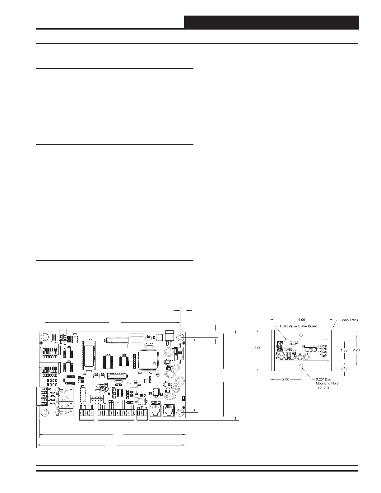
Figure 1: MHGRV III Controller Dimensions
Operator Interface 3
Page 4

MHGRV III Controller Technical Guide
Inputs and Outputs
General
The following inputs and outputs are available on the MHGRV III
controller For component locations of the inputs, outputs and wiring,
see Figures 2 and 3.
Analog Inputs
SAT: Supply Air Temperature Sensor
The Supply Air Temperature Sensor is the main control input. This sensor
has to be installed for the unit to operate. The Supply Air Temperature
Sensor is located in the discharge air stream and monitors the HVAC
unit’s Supply Air Temperature to maintain the Supply Air Temperature
Setpoint.
RESET IN: Reset Signal
The Discharge Temperature Setpoint can be reset by supplying a 0-10
VDC signal to the RESET IN low voltage terminal block. This reset
signal is optional and need only be used if you require resetting of the
discharge air temperature.
AUX IN: Valve Force Position Signal
The modulating HGR valves can be forced to a fi xed position by supply-
ing a 0-10 VDC signal to the AUX IN input. The setpoint and reset limit
switches must both be set to 1 to enable the valve force to work.
24 VAC Contact Closure Inputs
RHT EN: Dehumidifi cation
When a call for dehumidifi cation is initiated by another controller, this
interlocked 24 VAC wet contact closure is used to enable the MHGRV
III controller.
HEAT OVR: Heating Override
When a call for heating is initiated by the HVAC unit, this interlocked 24
VAC wet contact closure is used to override the MHGRV III controller
dehumidifi cation mode.
COOL OVR: Cooling Override
When a call for cooling is initiated by the HVAC unit, this interlocked 24
VAC wet contact closure is used to override the MHGRV III controller
dehumidifi cation mode.
Analog Outputs
AOUT 1: Valve Position Signal
The valve position signal is a 0-10 VDC signal that matches the position
of the valve. 0V = 0%, 10V = 100%.
Relay Outputs
COM: Relay Common
Requires 24 VAC from transformer.
FAN: Fan Enable
When a call for Dehumidifi cation, Cooling Override, or Heating Over-
ride is received, this relay output will be closed to energize the HVAC
unit Supply Fan.
CMP: Compressor Enable
When a call for Dehumidifi cation or Cooling Override is received, this
relay output will be closed to energize the Compressor(s).
VALVE: Reheat Solenoid Valve
When a call for Dehumidifi cation is active for 30 seconds, this relay
output will be closed to energize the Hot Gas Solenoid Valve.
AUX: 2 Position HGR Valve
Used on larger capacity systems that have an optional 2 Position HGR
Valve in addition to the Modulating HGR Valve. When a call for Dehumidifi cation is received and the modulating HGR valve is at 100%, this
relay output will be closed to energize the 2 Position HGR Valve. The
relay will open when the modulating HGR valve is at 0%.
Modulating HGR Valve Outputs
CG/HR:
This output is connected to the Condenser HGR Valve Green Wire
Termination and to the Reheat HGR Valve Red Wire Termination to
control their modulation.
CR/HG:
This output is connected to the Condenser HGR Valve Red Wire Termination and to the Reheat HGR Valve Green Wire Termination to control
their modulation.
CW/HW:
This output is connected to the Condenser HGR Valve White Wire
Termination and to the Reheat HGR Valve White Wire Termination to
control their modulation.
CB/HB:
This output is connected to the Condenser HGR Valve Black Wire
Termination and to the Reheat HGR Valve Black Wire Termination to
control their modulation.
4
Operator Interface
Page 5

MHGRV III Controller Technical Guide
Installation & Wiring
Controller Mounting
It is important to mount the controller in a location that is free from
extreme high or low temperatures, moisture, dust, and dirt.
Be careful not to damage the electronic components when mounting
the controller. Remove the controller from its snap track mount. Mark
the control enclosure base using the snap track as a template. Drill pilot
holes in the enclosure base and secure the snap track to it using sheet
metal screws. Do not allow metal shavings to fall onto the circuit board.
Reattach the controller to the snap track.
General Wiring Information
Please carefully read and apply the following information when wiring
the MHGRV III controller.
1. All 24 VAC wiring must be connected so that all ground
wires remain common. Failure to follow this procedure
can result in damage to the controller and connected
devices.
2. All wiring is to be in accordance with local and national
electrical codes and specifi cations.
3. Minimum wire size for 24 VAC wiring should be 18 gauge.
4. Minimum wire size for all sensors should be 24 gauge.
5. Be sure that all wiring connections are properly inserted and
tightened into the terminal blocks. Do not allow wire
strands to stick out and touch adjoining terminals which
could potentially cause a short circuit.
Important Wiring Considerations
Depending on if the MHGRV III controller is to be connected to the
HVAC controller or is to be used as a stand-alone controller determines
how the MHGRV III should be wired. For the wiring diagram to use
when the MHGRV III controller is connected to a VCM controller, see
Figure 2. For the wiring diagram to use when the MHGRV III controller
is connected to a VCM-X controller, see Figure 3. For the stand-alone
wiring diagram, see Figure 4. Please carefully read and apply the following information when wiring the MHGRV III controller.
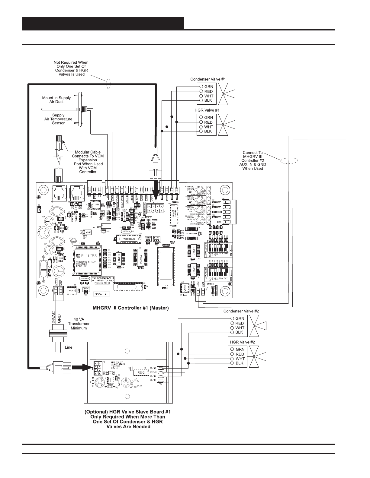
Additional Modulating Hot Gas Valve
Control
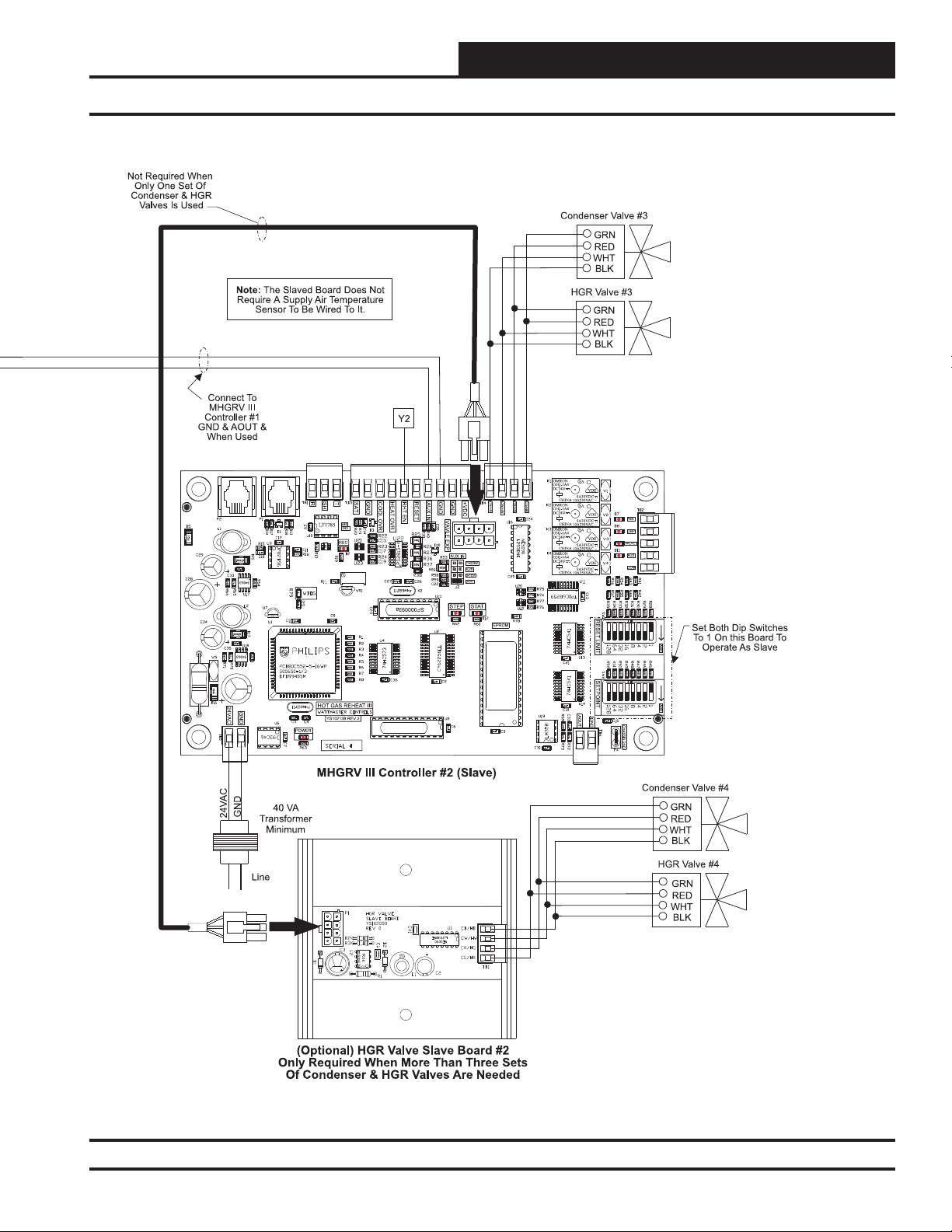
HGR Valve Slave Board
This board is connected to the MHGRV III board with a cable that plugs
into the connector labeled Valve Exp. This board provides control to an
additional set of modulating valves. The position of the valves will be
the same as the board they are plugged into.
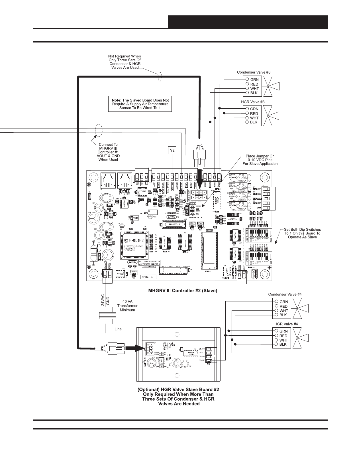
MHGRV III Slave Board Confi guration
Whenever the MHGRV III has both its setpoint switches set to 1, it will
work as a slave board. The board is active when it has a 24 VAC signal
on the RHT EN input. When the board is active, it looks for a 0-10
VDC on the AUX IN input and moves the HGR valves accordingly.
For example, if the input is at 10 VDC, then the reheat valve would be
100% open. If the voltage is at 5 VDC, the reheat valve would be 50%
open. See Figures 3 and 4.
Operator Interface
5
Page 6
MHGRV III Controller Technical Guide
Installation & Wiring
Figure 2: MHGRV III Controller Master To Slave Wiring When Used With VCM Controller (R46170)
6
Operator Interface
Page 7
MHGRV III Controller Technical Guide
Installation & Wiring
Figure 2, cont.: MHGRV III Controller Master To Slave Wiring When Used With VCM Controller (R46170)
Operator Interface
7
Page 8

MHGRV III Controller Technical Guide
Installation & Wiring
Figure 3: MHGRV III Controller Master To Slave Wiring When Used With VCM-X Controller (R69170)
8
Operator Interface
Page 9

MHGRV III Controller Technical Guide
Installation & Wiring
Figure 3, cont.: MHGRV III Controller Master To Slave Wiring When Used With VCM-X Controller (R69170)
Operator Interface
9
Page 10

MHGRV III Controller Technical Guide
Installation & Wiring
Figure 4: MHGRV III Controller Master to Slave Wiring - Stand Alone
10
Operator Interface
Page 11
MHGRV III Controller Technical Guide
Installation & Wiring
Figure 4, cont.: MHGRV III Controller Master To Slave Wiring - Stand Alone
Operator Interface
11
Page 12

MHGRV III Controller Technical Guide
DIP Switch Setting Shown
Is For A Setpoint Of 57
DIP Switch Setting Shown
Is For A Setpoint Of 94
ADD
ADD
32+16+8+1=57
64+16+8+4+2=94
All Rocker Switches Depressed
In the Direction Of The ADD Arrow
Are Added Together To Total The Setpoint
Typical DIP Switch
Detail View
F
1
O
F
ADD
4
2
16
8
64
32
128
DIP Switch Settings
Supply Air Temperature
The DIP switches are only used when the controller is installed as a
stand-alone controller. The main unit controller will set the Supply Air
Temperature Setpoint and Reset Limit when the MHGRV III is used as
an expansion device.
You can set the desired Discharge Air Temperature Setpoint using the DIP
Switch labeled SETPOINT. See Figure 5 for location and DIP Switch
setting instructions. The MHGRV III controller will allow you to set a
Supply Air Temperature Setpoint between 50°F and 100°F. If a value
of less than 50°F is set, the controller will default to a 50°F Supply Air
Temperature Setpoint. A value greater than 100°F will cause the unit to
default to a 100°F Supply Air Temperature Setpoint.
Supply Air Temperature Reset Limit
You can reset the Supply Air Temperature Setpoint by supplying a 0-10
VDC control signal to the Reset Input (RST IN) terminal on the MHGRV III controller board. The reset range is determined by the RESET
LIMIT DIP Switch. See Figure 5 for location and setting instructions.
The controller will reset the Supply Air Temperature Setpoint from the
value set on the SETPOINT DIP Switch to the value set on the RESET
LIMIT DIP Switch as the Reset Input (RST IN) signal is increased from
0 Volts to 10 Volts..
Example:
You want the Discharge Air Temperature Setpoint to increase from 55°F
when the Reset Input signal is at 0 Volts and to 75°F when the Reset
Input signal is at 10 Volts.
Set the SETPOINT DIP Switch to 55°F
Set the RESET LIMIT DIP Switch to 75°F
The discharge air temperature will now increase from 55°F to 75°F as
the Reset Input voltage signal ramps from 0 Volts to 10 Volts.
NOTE: It is possible to create a “reverse acting” control sequence.
Using the temperatures from the example above by setting the SETPOINT DIP Switch to 75F and the RESET
LIMIT DIP Switch to 55F, the reset would be reverse
acting. In this case, the controller will maintain a 75F
discharge temperature when the Reset Input signal is at
0 Volts and will reduce it to 55F when the Reset Input
signal is at 10 Volts.
Figure 5: DIP Switch Setting Instructions
12
Operator Interface
Page 13

MHGRV III Controller Technical Guide
DIP Switch Settings
Field Testing
For fi eld testing purposes, the modulating hot-gas valves can be forced
to full Cooling or full Reheat via DIP switch settings on the MHGRV
III controller. See Table 1 for mode of operation and valve positioning
during force modes.
MHGR Valve - Position & Operation
Setpoint Value Reset Limit
Value
1 3 Full Cooling 100% Closed
3 1 Full Reheat 100% Open
33
Table 1: MHGR Valve Position & Operation
Mode of
Operation
Half Reheat/
Cool
HGR Valve
Position
50% Open/
Close
NOTE: For a value of 1, only turn on DIP switch labeled 1. For a
value of 3, turn on DIP switches 1 and 2. The DIP switches
are added together to complete a specifi c value.
WARNING: When force mode testing is complete, reset the DIP
switch settings to a valid temperature setting.
Do not leave the MHGRV DIP switches set in force
mode when leaving the job site.
Operator Interface
13
Page 14

MHGRV III Controller Technical Guide
Start-up & Commissioning
General
In order to have a trouble free start-up, it is important to follow a few
simple procedures. Before applying power for the fi rst time, it is very
important to run through a few simple checks.
Power Wiring
One of the most important checks to make before powering up the
system for the fi rst time is to confi rm proper voltage and transformer
sizing for the controller. Each MHGRV III controller requires 40 VA of
power delivered to it at 24 VAC.
Check all wiring leads at the terminal block for tightness. Be sure that
wire strands do not stick out and touch adjacent terminals. Confi rm
that all sensors required for your system are mounted in the appropriate location and wired into the correct terminals on the MHGRV III
controller.
After all the above wiring checks are complete, apply power to the
MHGRV III controller.
Power Up and Operation
The MHGRV III Controller uses on-board LEDs to indicate various
diagnostic conditions during power-up and operation. The LEDs are
labeled, “STAT”. Starting with power up, the LED blink codes are as
follows:
STAT on for 10 seconds
STEP on for 10 seconds
STAT blinks 30 times
STEP on for 45 seconds
STAT blinks 3 times rapidly
Status code is repeatedly blinked every ten seconds to
indicate controller status
STEP LED will be on any time modulating valves move
See the Troubleshooting section of this manual for LED diagnostic
code information.
Programming the Controller
Stand-Alone
If the MHGRV III is used as a stand-alone controller, it does not require
programming. It does require the Supply Air Temperature SETPOINT
DIP Switch and the RESET LIMIT DIP Switch (if required) be correctly
set for the required Supply Air Temperature and the Supply Air Reset
Temperature.
When Used with an HVAC Unit Controller
When the MHGRV III controller is connected to an HVAC Unit controller, the HVAC unit controller must be programmed with the desired
Supply Air Temperature Setpoint and Supply Air Temperature Reset
Setpoint and other confi guration information. In order to confi gure and
program the HVAC unit controller, you must have a central operator’s
interface or a personal computer with the Prism II computer front-end
software installed.
Two different operator interfaces are available for programming of the
HVAC unit controller to access the status and setpoints of the HVAC
unit controller—the Modular Service Tool or the Modular System Man-
ager. See the Modular Service Tool and System Manager Programming
Guide for programming information. If you are going to use a personal
computer and the Prism computer front-end software, please refer to the
Prism II Technical Guide. No matter which operator interface you use,
it is recommended that you proceed with the programming and setup
of the controller in the order that follows:
1. Confi gure the controller for your application
2. Program the controller setpoints
3. Review controller status screens to verify system
operation and correct controller confi guration
Modular Service Tool
The modular service tool can be used to check the status of the MHGRV
III board. You can do this if the board is stand-alone or being used with
an HVAC unit controller.
NOTE: Modular Service Tool must have software version 3.30
or later.
After you press the Status button on the handheld, the following screens
will appear:
Enter 56 for the MHGRV III
board.
If unit has Reheat Active, this
screen will appear:
If Reheat isn’t active, you will
see this screen:
Unit Selection
Enter Unit ID#
Selected ID#: 56
Unit Active
Supply Air: X.XF
Setpoint: X.XF
Valve Pos: X.X%
Unit Off
Supply Air: X.XF
Setpoint: X.XF
Valve Pos: X.X%
14
Operator Interface
Page 15

MHGRV III Controller Technical Guide
Sequence of Operation
Initialization
As described on the previous page under the heading, “Power Up and
Operation,” the MHGRV III Controller uses on-board LEDs to indicate
various diagnostic conditions during power-up and operation. Please
review this information for a complete description of the controller
initialization sequence.
Modulating Hot Gas Valves
The MHGRV III Controller utilizes two modulating Hot Gas Reheat
Valves to control the fl ow of Hot Gas through the Hot Gas Reheat Coil.
One of these valves is the Condenser Hot Gas Valve and the other is
the Reheat Hot Gas Valve. The valves are wired to the MHGRV III
Controller Modulating Hot Gas Valve Output terminals on the controller. These valves work in concert with each other to create a “three-way
valve” confi guration. As one closes, the other opens, etc. All modes of
operation that follow referring to the Hot Gas Reheat Valve are actually a combination of these two valves working together to achieve the
specifi ed sequence of operation.
Modes of Operation
The MHGRV III Controller can be used in two different modes of operation. These modes behave in a similar manner; the main difference is the
way they receive information to control the dehumidifi cation process.
The following is a description of these modes:
Stand-Alone Operation
As the name implies, in this mode the controller behaves as an independent unit. The controller begins the dehumidifi cation process when
the Dehumidifi cation Input “H1” receives a 24 VAC signal from an
outside source. When the signal is received, the controller will activate
the “FAN” output to energize the HVAC unit fan. At the same time, the
controller will initiate Cooling Mode by energizing the “CMP” output
starting the HVAC unit compressor. In addition, the controller will open
the Hot Gas Reheat Coil by activating the “VALVE” output. At this time,
the MHGRV III Controller will start to modulate the Modulating Hot Gas
Reheat valve. The controller will modulate the MHGR valve to maintain
the Supply Air Temperature Setpoint by activating the stepper motor
outputs on the MHGR valve. The Supply Air Setpoint is confi gured
by setting the SETPOINT DIP Switch on the MHGRV III Controller. If
Supply Air Temperature Reset is used, it will initiate when a 0-10 VDC
signal is supplied to the “RESET IN” input. As the voltage increases
from 0 to 10 Volts at the “RESET IN” input, the Supply Air Temperature
will be reset towards the Supply Air Reset Temperature Setpoint. This
setpoint is confi gured by setting the RESET DIP Switch on the MHGRV
III Controller. When a 10 Volt input signal is received at the “RESET
IN” input, it will be controlling at the Supply Air Temperature Reset
Setpoint. The controller will conclude the Dehumidifi cation process
when input “H1” is deactivated, the input “Cool Override” is activated,
or the input “Heat Override” is activated.
Operation as an Expansion Board
In this mode, the MHGRV III Controller behaves as an expansion board
for a VCM controller. The controller begins the dehumidifi cation pro-
cess when the HVAC Unit controller makes a request to the MHGRV
III Controller for dehumidifi cation. At that time, the controller will
activate the “FAN” output to energize the HVAC unit fan. At the same
time, the controller will initiate Cooling Mode by energizing the “CMP”
output starting the HVAC unit compressor. In addition, the controller
will open the Hot Gas Reheat Coil by activating the “VALVE” output
which opens the Reheat Solenoid Valve. At this time, the MHGRV III
Controller will start to modulate the Modulating Hot Gas Reheat valve.
The controller will modulate the MHGR valve to maintain the Supply
Air Temperature Setpoint by activating the stepper motor outputs on
the MHGR valve. The Supply Air Setpoint is set by programming the
HVAC unit controller. If Supply Air Temperature Reset is used, it will
initiate when the HVAC sends a request to reset the Supply Air Temperature. The Supply Air Temperature will be reset towards the Supply Air
Reset Temperature Setpoint stored in the HVAC controller. It will send
a request to move towards the Supply Air Temperature Reset Setpoint
based on its setpoints and confi guration. The controller will conclude
the Dehumidifi cation process when the HVAC control sends a request to
terminate Dehumidifi cation or a Cooling or Heating Override request is
made by the HVAC unit controller. Any DIP switch settings or signals
at the inputs to the MHGRV III Controller will be ignored.
Additional Features
The following are features which are also designed into the MHGRV
III Controller:
Reheat Coil Flush
To assure positive oil return to the compressor, the Hot Gas Reheat
Coil will be fl ushed of liquid refrigerant by moving the Modulating
Gas Reheat Valve to its maximum position for a short interval. If the
unit is in cooling mode, a fl ush will occur every hour. If the unit is in
dehumidifi cation mode and the valve is below 70% for 20 minutes, a
fl ush will occur.
Optional Second Stage Reheat
On larger systems, where more hot gas reheat capacity may be required,
a 2 Position Hot Gas Reheat valve can be connected to the MHGRV III
Controller to be used in conjunction with the Modulating Hot Gas Reheat
valve. Any time the reheat demand moves above the Modulating Hot Gas
Reheat valve capacity, this 2 position valve would be energized to supply
additional hot gas to the Hot Gas Reheat coil. As the reheat demand is
satisfi ed, the MHGRV III Controller will de-energize the 2 position valve
and control reheat with the Modulating Hot Gas Reheat valve.
Reheat Solenoid Valve Control
The Hot Gas Reheat Solenoid valve for the Reheat Coil is activated when
there is a call for Dehumidifi cation. In this mode, the Hot Gas Reheat
Solenoid will be deactivated 2 minutes after the reheat demand ceases.
The Hot Gas Reheat Solenoid valve will be reactivated when a request
for reheat is received by the MHGRV III Controller.
Operator Interface
15
Page 16
MHGRV III Controller Technical Guide
Troubleshooting
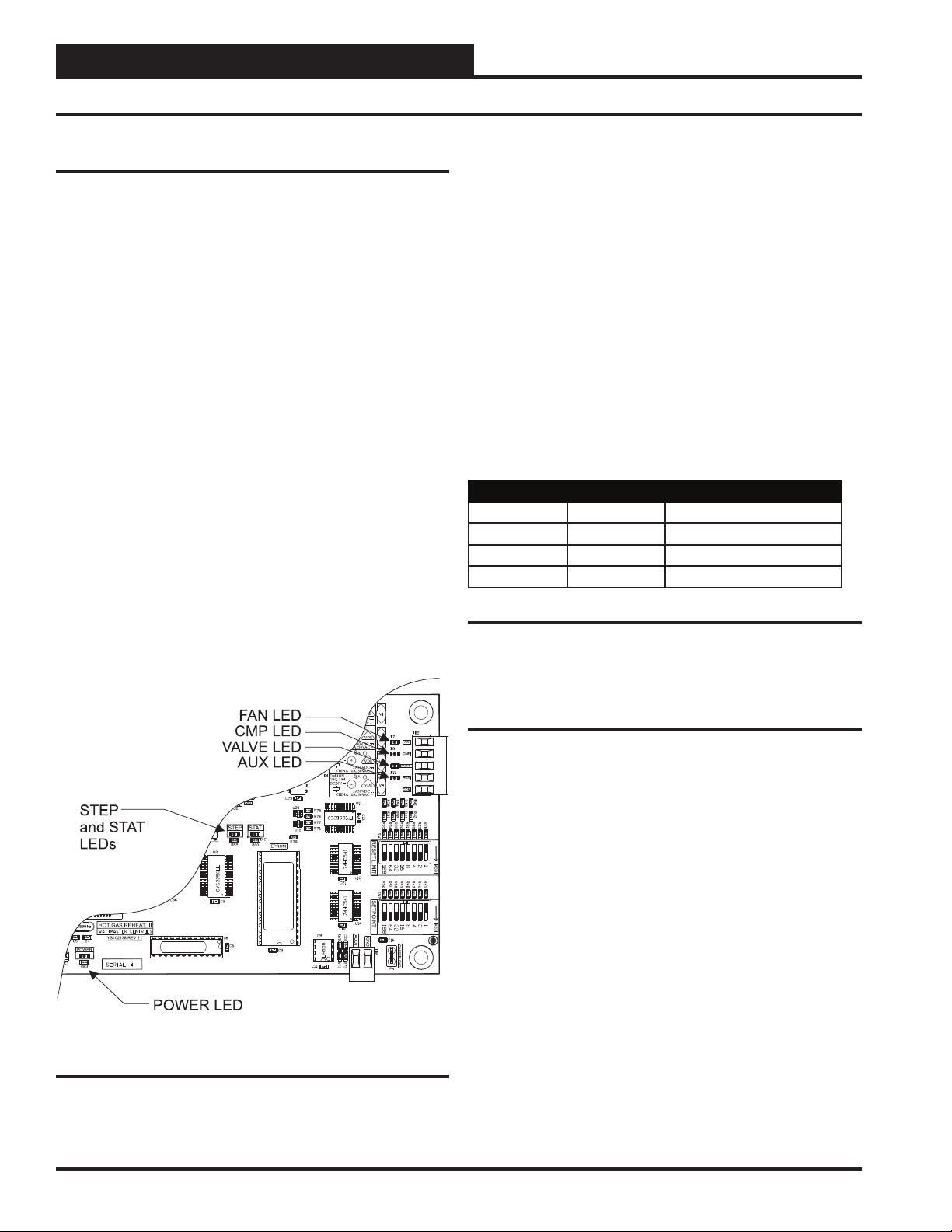
Using LEDs to Verify Operation
The MHGRV III controller is equipped with LEDs that can be used as
very powerful troubleshooting tools. The MHGRV III controller board
has six LEDs. Two of these LEDs are used in troubleshooting. See Figure
6 for the LED locations. The LEDs and their uses are as follows:
LED Descriptions
“STAT ” - This is the diagnostic blink code LED. It will light up and
blink out diagnostic codes. See Table 2 for blink codes.
“STEP” - This LED is on any time the modulating hot gas reheat valve
is moving.
“POWER” - This LED will light up to indicate that 24 VAC power has
been applied to the controller.
“FAN” - This light indicates that the relay for the “FAN” output is
energized and its Normally Open Contact is closed.
“CMP” - This light indicates that the relay for the “CMP” output is
energized and its Normally Open Contact is closed.
“VALVE” - This light indicates that the relay for the “VALVE” output
is energized and its Normally Open Contact is closed.
LED Diagnostics
“POWER” LED: When the MHGRV III Controller is powered up,
the POWER LED should light up and stay on continuously. If it does
not light up, check to be sure that the power wiring is connected to the
board, the connections are tight, and the transformer is powered. If after
making all these checks, the POWER LED does not light up, the board
is probably defective.
“STAT” LED: As previously described, when the board is fi rst powered
up, the STAT LED will do the following:
On for 10 seconds
Blinks 30 times
Blinks 3 times rapidly (after STEP LED is on
for 45 seconds)
Status code is repeatedly blinked every ten seconds to
indicate controller status
Priority No. of Blinks Status
Lowest 1 Normal Operation
- 2 SAT Over High Limit (170º)
- 3 Bad SAT Sensor
Highest 4 Force Mode Active
“AUX” - This light indicates that the relay for the “AUX” output is
energized and its Normally Open Contact is closed.
Table 2: STAT LED Blink Codes
Only the highest priority failure code will be shown. You must correct
the highest priority alarm before other problems will be indicated.
Other Checks
Supply Air Temperature Sensor
If you suspect the Supply Air Temperature Sensor is not reading correctly, make sure the wiring terminal connections are tight and that any
wiring splices are properly connected. You can check the operation of the
Supply Air Temperature Sensor by measuring the resistance or voltage
using a digital multimeter. Set the meter to DC Volts. Place the positive
probe on the AIN terminal and the negative probe on the GND terminal.
Read the DC Volts and fi nd that voltage in Table 3.
Read the temperature corresponding with that voltage and determine
if this is close to the actual temperature the sensor is exposed to. If the
temperature from the chart is different by more than a few degrees, you
probably have a defective or damaged sensor. You can also check the
sensor resistance to determine correct operation. To read the resistance,
set the meter to Ohms. Unplug the sensor connector from the board and
measure the resistance across the disconnected wires. This resistance
should match the corresponding temperature from Table 3.
Figure 6: LED Locations
16
Operator Interface
Page 17
MHGRV III Controller Technical Guide
Troubleshooting
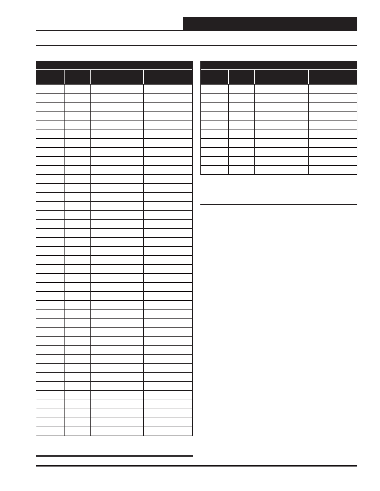
Temperature to Resistance/Voltage Chart
Temp
(°F)
-10 -23.3 93333 4.620
-5 -20.6 80531 4.550
0 -17.8 69822 4.474
5 -15.0 60552 4.390
10 -12.2 52500 4.297
15 -9.4 45902 4.200
20 -6.7 40147 4.095
25 -3.9 35165 3.982
30 -1.1 30805 3.862
35 1.6 27140 3.737
40 4.4 23874 3.605
45 7.2 21094 3.470
50 10.0 18655 3.330
52 11.1 17799 3.275
54 12.2 16956 3.217
56 13.3 16164 3.160
58 14.4 15385 3.100
60 15.6 14681 3.042
62 16.7 14014 2.985
64 17.8 13382 2.927
66 18.9 12758 2.867
68 20.0 12191 2.810
69 20.6 11906 2.780
70 21.1 11652 2.752
71 21.7 11379 2.722
72 22.2 11136 2.695
73 22.7 10878 2.665
74 23.3 10625 2.635
75 23.9 10398 2.607
76 24.4 10158 2.577
78 25.6 9711 2.520
80 27.8 9302 2.465
82 27.8 8893 2.407
84 28.9 8514 2.352
86 30.0 8153 2.297
88 31.1 7805 2.242
90 32.2 7472 2.187
95 35.0 6716 2.055
100 37.8 6047 1.927
Temp
(°C)
Resistance (Ohms) Voltage @
Input (VDC)
Temperature to Resistance/Voltage Chart
Temp
(°F)
105 40.6 5453 1.805
110 43.3 4923 1.687
115 46.1 4449 1.575
120 48.9 4030 1.469
125 51.7 3656 1.369
130 54.4 3317 1.274
135 57.2 3015 1.185
140 60.0 2743 1.101
145 62.8 2502 1.024
150 65.6 2288 0.952
Temp
(°C)
Resistance (Ohms) Voltage @
Input (VDC)
Table 3, cont.: Temperature Sensor - Voltage &
Resistance for Type III Sensors
Thermistor Sensor Testing Instructions
1.) Use the resistance column to check the thermistor sensor while
disconnected from the controllers (not powered).
2.) Use the voltage column to check sensors while connected to powered controllers. Read voltage with meter set on DC volts. Place the “-”
(minus) lead on GND terminal and the “+” (plus) lead on the sensor
input terminal being investigated.
If the voltage is above 5.08 VDC, the sensor or wiring is “open.” If the
voltage is less than 0.05 VDC, the sensor or wiring is shorted.
Table 3: Temperature Sensor - Voltage &
Resistance for Type III Sensors
Operator Interface
17
Page 18

MHGRV III Controller Technical Guide
Notes
18
Operator Interface
Page 19

MHGRV III Controller Technical Guide
Notes
Operator Interface
19
Page 20

2425 So. Yukon Ave • Tulsa, OK • 74107-2728
Ph: (918) 583-2266 • Fax: (918) 583-6094
WM Form: AA-MHGRVIII-TGD-01D
Printed in the USA • Copyright 2011 • All Rights Reserved • August 2011
WattMaster Controls, Inc. • 8500 NW River Park Drive • Parkville, MO • 64152
AAON® Part No.: R76540
 Loading...