

Page 1
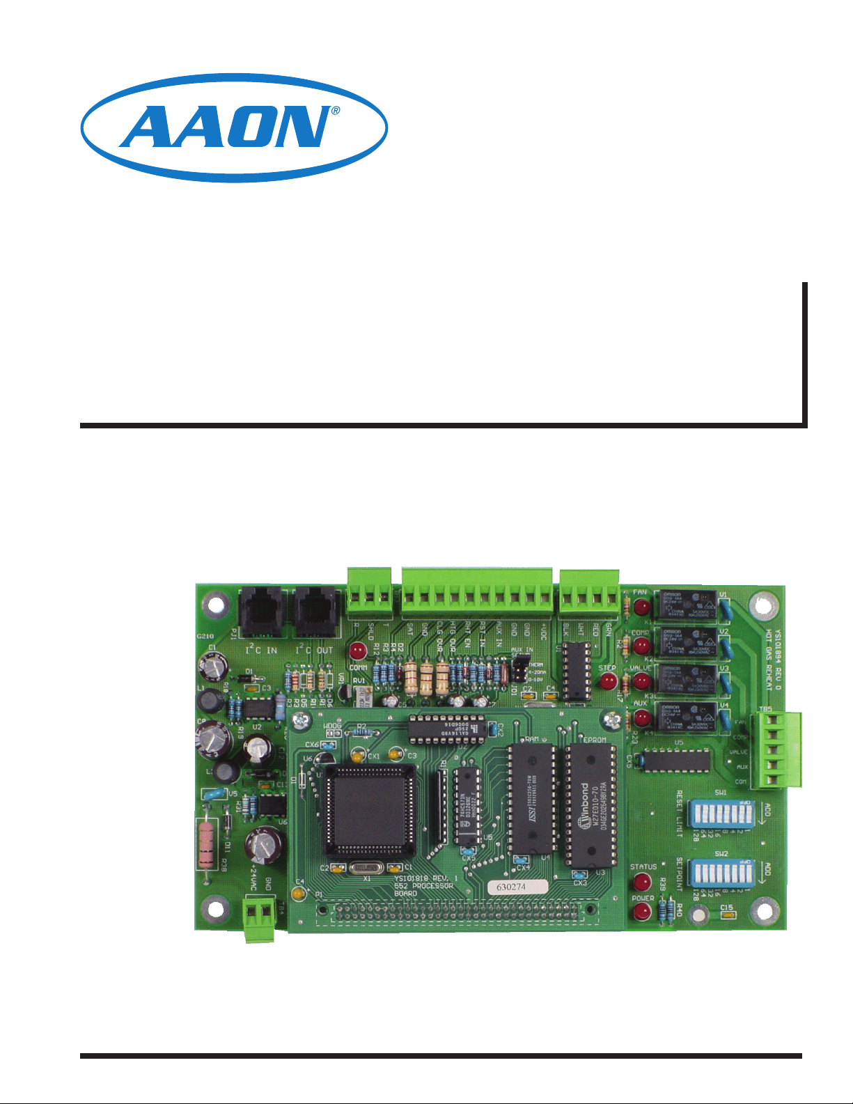
MHGRV II Controller
Technical Guide
Page 2

Table Of Contents
Controller Overview ......................................................................................................................................... 3
General.........................................................................................................................................................................................3
Features .......................................................................................................................................................................................3
Operation......................................................................................................................................................................................3
Controller Inputs and Outputs ......................................................................................................................... 4
General.........................................................................................................................................................................................4
Analog Inputs ...............................................................................................................................................................................4
24 VAC Contact Closure Inputs: ...................................................................................................................................................4
Controller Installation & Wiring ...................................................................................................................... 4
Controller Mounting ...................................................................................................................................................................... 4
Relay Outputs...............................................................................................................................................................................4
Modulating HGR Valve Outputs ...................................................................................................................................................4
Important Wiring Considerations .................................................................................................................................................. 4
DIP Switch Settings ......................................................................................................................................... 7
Supply Air Temperature ................................................................................................................................................................ 7
Supply Air Temperature Reset Limit ............................................................................................................................................7
Start-up & Commissioning............................................................................................................................... 8
General.........................................................................................................................................................................................8
Power Wiring ............................................................................................................................................................................... 8
Power Up And Operation..............................................................................................................................................................8
Programming The Controller ........................................................................................................................................................8
Sequence Of Operation ................................................................................................................................... 9
Initialization...................................................................................................................................................................................9
Modulating Hot Gas Valves ..........................................................................................................................................................9
Modes Of Operation ..................................................................................................................................................................... 9
Additional Features ......................................................................................................................................................................9
Troubleshooting ............................................................................................................................................. 10
Using LED’s To Verify Operation ................................................................................................................................................ 10
Other Checks .............................................................................................................................................................................10
WattMaster Controls Inc.
8500 NW River Park Drive · Parkville , MO 64152
Toll Free Phone: 866-918-1100
PH: (816) 505-1100 · FAX: (816) 505-1101 · E-mail: mail@wattmaster.com
Visit our web site at www.orioncontrols.com
AAON® Part No.: R12200
WattMaster Form: AA-MHGRVII-TGD-01E
Copyright September 2011 WattMaster Controls, Inc.
AAON is a registered trademark of AAON, Inc., Tulsa, OK.
WattMaster Controls, Inc. assumes no responsibility for errors, or omissions.
This document is subject to change without notice.
Page 3
Controller Overview
Technical Guide
General
The MHGRV II Controller is designed to control a Modulating Hot
Gas Reheat Valve to maintain a desired Supply Air Temperature and
Humidifi cation setpoint . The controller can be used as a stand-alone
controller or it can be connected to and used in conjunction with the
AAON Factory Packaged HVAC unit controller. The MHGRV II controller is connected to the HVAC unit controller via a modular expansion
cable and corresponding connectors on the controllers.
Features
The MHGRV II provides the following features.
Can Be Operated as a Stand-Alone Controller or Integrated
with the HVAC Unit Controller
Provides for Supply Air Temperature Setpoint
Reset when Required
Second Stage Reheat Capability When Using
2 Hot Gas Reheat Valves
Control of Reheat Solenoid Valve to
Provide Coil Flushing for Positive Refrigerant Oil
Return
Operation
When used in a stand-alone application (not connected to an HVAC unit
controller board) the MHGRV II controller will control the Modulating
Hot Gas Valve to maintain the Supply Air Setpoint based on the Supply
Air Temperature Sensor connected to the MHGRV II controller. The
MHGRV II controller is activated by a 24 VAC wet contact closure
signal connected to the H1 (RHT EN) input terminal on the controller.
Heating Override and Cooling Override are also controlled by 24 VAC
wet contact closure signals connected to the HTG OVR and CLG OVR
input terminals on the controller. The Supply Air Setpoint is set by
confi guring a DIP switch on the MHGRV II controller board. Supply
Air Temperature Reset is also available and is set by confi guring a DIP
switch on the controller board. When Supply Air Temperature Reset is
used it is reset by a 0-10 VDC signal supplied to the RST IN terminal
on the MHGRV II controller.
When the MHGRV II controller is connected to an HVAC unit controller board via its modular cable it will operate exactly as the stand-alone
controller except the following information will be passed between the
MHGRV II controller and the HVAC unit controller.
Reheat Enable command
Supply Air Temperature Setpoint. This replaces the
setpoint that is set with the Supply Air Temperature DIP
switch on the MHGRV II controller.
The Reset Supply Air Temperature Setpoint. This replaces
the setpoint that is set with the Supply Air Temperature
Reset DIP switch on the MHGRV II controller. The Supply
Air Temperature Reset Signal is also supplied from the
HVAC unit controller.
If the communication is interrupted between the MHGRV
II controller and the HVAC unit controller, the
MHGRV II controller will revert to stand-alone operation.
TB3
SHLD
R
COMM
VR1
T
R12
PU
D2
R4
RV1
R2
C3
CX1
C1
X1
YS101818P552
PROCESSOR
BOARD
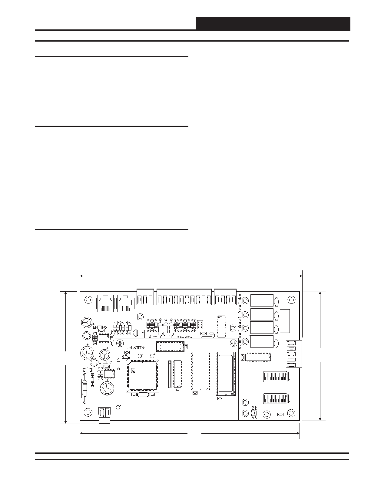
4.80"
PJ1
C1
2
ICIN
D1
R18
L1
R19
C8
L2
V5
R31
D11
R38
+24VAC
2
ICOUT
C3
U2
GND
C13
TB4
R11
D5
D6
R3
R1
R3
R20
WDOG
C12
CX6
U6
U1
D1
D1
C2
C4
P1
Figure 1: MHGRV II Controller Dimensions
8.10"
FAN
CW/HW
CB/HB
CR/HG
EPROM
STEP
U3
CG/HR
R2
R17
COMP
VALV E
AUX
R23
CX5
STATUS
POWER
K1
K2
K3
K4
R39
CLG OVR
GND
SAT
R1
1
HTG OVR
R5R6D4
U2
CX5
RST IN
RHT IN
R13
R7
D3
CX2
U5
R8
AUX IN
AUX IN
SETUP
R9
RAM
CX4
GND
GND
THERM
4-20MA
0-10V
C2
+VDC
U1
C4
U4
CX3
U5
RESET LIMIT
SETPOINT
R40
128
64
32
1286416
32
SW1
16
SW2
V1
V2
V3
V4
8
8
FAN
COMP
VALV E
AUX
COM
421
4
C15
YS101894 REV 1
HOT GAS REHEAT
SERIAL #
TB5
4.69"
ADD
ADD
1
2
8.01"
VAV/Zone Controller 3
Page 4

Technical Guide
Controller Inputs and Outputs
General
The following inputs and outputs are available on the MHGRV II controller For component locations of the inputs, outputs and wiring, see
Figure 3 and 4.
Analog Inputs
SAT: Supply Air Temperature Sensor
The Supply Air Temperature Sensor is the main control input. This sensor
has to be installed for the unit to operate. The Supply Air Temperature
Sensor is located in the discharge air stream and monitors the HVAC
units Supply Air Temperature to maintain the Supply Air Temperature
Setpoint.
RST IN: Reset Signal
The Discharge Temperature Setpoint can be reset by supplying a 0-10
VDC signal to the RST IN low voltage terminal block. This reset signal
is optional and need only be used if you require resetting of the discharge
air temperature.
AUX IN: Not Used
24 VAC Contact Closure Inputs:
RHT EN: Dehumidifi cation
When a call for dehumidifi cation is initiated by another controller this
interlocked 24 VAC wet contact closure is used to enable the MHGRV
II controller.
HTG OVR: Heating Override
When a call for heating is initiated by the HVAC unit, this interlocked
24 VAC wet contact closure is used to override the MHGRV II controller
dehumidifi cation mode.
CLG OVR: Cooling Override
When a call for cooling is initiated by the HVAC unit, this interlocked
24 VAC wet contact closure is used to override the MHGRV II controller
dehumidifi cation mode.
Relay Outputs
FAN: Fan Enable
When a call for Dehumidifi cation, Cooling Override or Heating Over-
ride is received, this relay output will be closed to energize the HVAC
unit Supply Fan.
COMP: Compressor Enable
When a call for Dehumidifi cation or Cooling Override is received this
relay output will be closed to energize the Compressor(s).
VALVE: Reheat Solenoid Valve
When a call for Dehumidifi cation is received and reheat is required this
relay output will be closed to energize the Hot Gas Solenoid Valve approximately 30 seconds after the Fan and Compressor have been enabled.
AUX: 2 Position HGR Valve
Used on larger capacity systems that have an optional 2 Position HGR
Valve in addition to the Modulating HGR Valve. When a call for Dehumidifi cation is received and additional reheat is required beyond the
Modulating HGR valves capacity, this relay output will be closed to
energize the 2 Position HGR Valve, while the Reheat Solenoid Valve
continues to modulate as required. This AUX (2 Position HGR Valve)
Relay will energize when the Modulating HGR Valve stays at 100% for 1
½ minutes. The AUX Relay will de-energize when the Modulating HGR
Valve stays at 0% for 1½ minutes. The AUX Relay is not be energized
during the Dehumidifi cation Reheat Coil Flush Cycle.
Modulating HGR Valve Outputs
CG/HR:
This output is connected to the Condensor HGR Valve Green Wire
Termination and to the Reheat HGR Valve Red Wire Termination to
control their modulation.
CR/HG:
This output is connected to the Condensor HGR Valve Red Wire Termination and to the Reheat HGR Valve Green Wire Termination to control
their modulation.
CW/HW:
This output is connected to the Condensor HGR Valve White Wire
Termination and to the Reheat HGR Valve White Wire Termination to
control their modulation.
CB/HB:
This output is connected to the Condensor HGR Valve Black Wire
Termination and to the Reheat HGR Valve Black Wire Termination to
control their modulation.
Controller Installation & Wiring
Controller Mounting
It is important to mount the controller in a location that is free from
extreme high or low temperatures, moisture, dust and dirt.
Be careful not to damage the electronic components when mounting
the controller. Remove the controller from its snap track mount. Mark
the control enclosure base using the snap track as a template. Drill pilot
holes in the enclosure base and secure the snap track to it using sheet
metal screws. Do not allow metal shavings to fall onto the circuit board.
Reattach the controller to the snap track.
4
Important Wiring Considerations
Depending on if the MHGRV II controller is to be connected to the
HVAC controller or is to be used as a stand-alone controller determines
how the MHGRV II should be wired. For the stand-alone wiring diagram, see Figure 2. For the wiring diagram to use when the MHGRV
II controller is connected to an HVAC controller, see Figure 3. Please
carefully read and apply the following information when wiring the
MHGRV II controller.
MHGRVII Controller
Page 5

Technical Guide
Please carefully read and apply the following information when wiring
the MHGRV II controller.
1. All 24 VAC wiring must be connected so that all ground
wires remain common. Failure to follow this procedure
can result in damage to the controller and connected
devices.
2. All wiring is to be in accordance with local and national
electrical codes and specifi cations.
“AUX” Relay LED
Reheat
Modulating
HG Valve
Green
Red
White
Black
Condensor
Modulating
HG Valve
Green
Red
White
Black
0-10VDC
External Reset
H1 (Dehumidification)
Heating Override
Cooling Override
Supply
Air Temperature
Sensor
Mount In Supply
Air Duct
Signal
“VALVE” Relay LED
“COMP” Relay LED
“FAN” Relay LED
V1
FAN
+
TB3
YS101894 REV 1
HOT GAS REHEAT
SERIAL #
V2
K1
COMP
R2
CG/HR
CR/HG
CW/HW
CB/HB
U1
+VDC
GND
GND
AUX IN
AUX IN
RST IN
RHT EN
HTG OVR
CLG OVR
GND
SAT
D2
R4
PU
T
R12
SHLD
R
2
I C OUT
2
ICIN
PJ1
C1
K2
SETUP
COMM
V3
VALVE
STEP
THERM
4-20MA
VR1
D1
R17
0-10V
RV1
R18
C4
C2
R9
R8
D4
R13
R7
D3
R6
R5
C3
3. Minimum wire size for 24 VAC wiring should be 18
gauge.
4. Minimum wire size for all sensors should be 24 gauge.
5. Be sure that all wiring connections are properly inserted
and tightened into the terminal blocks. Do not allow wire
strands to stick out and touch adjoining terminals which
could potentially cause a short circuit.
Fan
C1
Compressor
C2
HGR Solenoid Valve
2 Position HGR Valve (Optional)
24 VAC
TB5
FAN
COMP
V4
U5
K3
K4
AUX
R23
EPROM
RAM
CX2
R2
D6
R11
WDOG
R1
D5
R3
R3
R20
U2
R19
C8
L1
ADD
AUX
COM
VALVE
SW1
RESET LIMIT
CX5
U2
R1
1
C3
CX1
U1
CX6
U6
D1
D1
C12
C13
R31
V5
L2
ADD
F
FOF
F
O
1
4
8
16
32
64
128
2
U5
SW2
SETPOINT
D11
R38
U4
CX5
C1
C2
+24VAC
STATUS
U3
CX3
CX4
X1
GND
1
2
4
8
16
32
64
128
R40
R39
POWER
YS101818
552 PROCESSOR
BOARD
P1
C4
TB4
C15
Reset Limit
DIP Switch
Must Be Set
For Required
Reset Supply
Air Temperature
Setpoint
DIP Switch
Must Be Set
For Required
Supply Air
Temperature
“POWER” LED
“STATUS” LED
EPROM Chip
RAM Chip
40 VA
Transformer
Minimum
Figure 2: MHGRV II Controller Wiring When Used As A Stand-Alone Controller
MHGRVII Controller
24VAC
GND
Line
5
Page 6

Technical Guide
Controller Installation & Wiring
“AUX” Relay LED
Reheat
Modulating
HG Valve
Green
Red
White
Black
Modulating
HGR Valve
Green
Red
White
Black
Air Temperature
Mount In Supply
Air Duct
Supply
Sensor
Modular Cable
Connect To
HVAC Unit
Controller
“VALVE” Relay LED
“COMP” Relay LED
“FAN” Relay LED
V1
FAN
TB3
YS101894 REV 1
HOT GAS REHEAT
SERIAL #
V2
K1
COMP
R2
CG/HR
CR/HG
CW/HW
CB/HB
U1
+VDC
GND
GND
AUX IN
AUX IN
RST IN
RHT EN
HTG OVR
CLG OVR
GND
SAT
D2
R4
PU
T
R12
SHLD
R
2
I C OUT
2
ICIN
PJ1
C1
V3
K2
THERM
SETUP
COMM
VALVE
STEP
D1
R17
4-20MA
0-10V
RV1
VR1
Fan
C1
Compressor
C2
HGR Solenoid Valve
2 Position HGR Valve (Optional)
24 VAC
Reset Limit
DIP Switch
(Not Used
TB5
FAN
COMP
V4
U5
K3
K4
AUX
R23
EPROM
C4
C2
RAM
R9
R8
D4
CX2
R13
R7
D3
R6
R5
R2
D6
R11
WDOG
R1
D5
R3
R3
R20
C3
U2
R19
R18
C8
L1
ADD
AUX
COM
VALVE
SW1
RESET LIMIT
CX5
U2
R1
1
C3
CX1
U1
CX6
U6
D1
D1
C12
C13
R31
V5
L2
ADD
F
FOF
F
O
1
2
4
8
16
32
64
128
U5
SW2
SETPOINT
STATUS
U3
CX3
U4
CX4
CX5
C1
X1
C2
GND
1
2
4
8
16
32
64
128
R40
R39
POWER
YS101818
552 PROCESSOR
BOARD
P1
C4
TB4
C15
+24VAC
D11
R38
For This
Application)
Setpoint
DIP Switch
(Not Used
For This
Application)
“POWER” LED
“STATUS” LED
EPROM Chip
RAM Chip
Not Required if Using
MODGAS II Controller
On HVAC Unit
24VAC
40 VA
Transformer
Minimum
Line
Figure 3: MHGRV II Controller Wiring When Used In Conjunction With A HVAC Controller
6
MHGRVII Controller
GND
Page 7

DIP Switch Settings
Technical Guide
Supply Air Temperature
The DIP switches are only used when the controller is installed as a
stand-alone controller. The main unit controller will set the Supply Air
Temperature Setpoint and Reset Limit when the MHGRV II is used as
an expansion device.
The user can set the desired Discharge Air Temperature Setpoint using
the DIP Switch labeled SETPOINT. See Figure 4 for location and DIP
Switch setting instructions. The MHGRV II controller will allow the user
to set a Supply Air Temperature Setpoint between 50°F and 100°F. If a
value of less than 50°F is set, the controller will default to a 50°F Supply
Air Temperature Setpoint, a value greater than 100°F will cause the unit
to default to a 100°F Supply Air Temperature Setpoint.
Supply Air Temperature Reset Limit
The user can reset the Supply Air Temperature Setpoint by supplying
a 0-10 VDC control signal to the Reset Input (RST IN) terminal on the
MHGRV II controller board. The reset range is determined by the RESET
LIMIT DIP Switch. See Figure 4 for location and setting instructions.
The controller will reset the Supply Air Temperature Setpoint from the
value set on the SETPOINT DIP Switch to the value set on the RESET
LIMIT DIP Switch, as the Reset Input (RST IN)
signal is increased from 0 Volts to 10 Volts..
Example:
We want the Discharge Air Temperature Setpoint to increase from 55°F
when the Reset Input signal is at 0 Volts, to 75°F when the Reset Input
signal is at 10 Volts.
Set the SETPOINT DIP Switch to 55°F
Set the RESET LIMIT DIP Switch to 75°F
The discharge air temperature will now increase from 55°F to 75°F as
the Reset Input voltage signal ramps from 0 Volts to 10 Volts.
Note: It is possible to create a “reverse acting” control sequence.
Using the temperatures from the example above by setting the SETPOINT DIP Switch to 75F and the RESET
LIMIT DIP Switch to 55F, the reset would be reverse
acting. In this case the controller will maintain a 75F
discharge temperature when the Reset Input signal is at
0 Volts and will reduce it to 55F when the Reset Input
signal is at 10 Volts.
All Rocker Switches Depressed
In the Direction Of The ADD Arrow
Are Added Together To Total The Setpoint
32+16+8+1=57
ADD
ADD
O
F
F
1
2
4
8
16
32
64
128
Typical DIP Switch
Detail View
64+16+8+4+2=94
ADD
DIP Switch Setting Shown
Is For A Setpoint Of 57
Figure 4: DIP Switch Setting Instructions
MHGRVII Controller
DIP Switch Setting Shown
Is For A Setpoint Of 94
7
Page 8

Technical Guide
Start-up & Commissioning
General
In order to have a trouble free start-up it is important to follow a few
simple procedures. Before applying power for the fi rst time it is very
important to run through a few simple checks.
Power Wiring
One of the most important checks to make before powering up the system
for the fi rst time, is to confi rm proper voltage and transformer sizing
for the controller. Each MHGRV II controller requires 40 VA of power
delivered to it at 24 VAC.
Check all wiring leads at the terminal block for tightness. Be sure that
wire strands do not stick out and touch adjacent terminals. Confi rm that
all sensors required for your system are mounted in the appropriate location and wired into the correct terminals on the MHGRV II controller.
After all the above wiring checks are complete, apply power to the
MHGRV II controller.
Power Up And Operation
The MHGRV II Controller uses an on board LED to indicate various
diagnostic conditions during power-up and operation. The LED is labeled
“STATUS”. Starting with power up the LED blink codes are as follows:
One Blink
Off for fi ve seconds
Blinks 30 times
Blinks 3 times rapidly
Status code is repeatedly blinked every ten seconds to
indicate controller status
Programming The Controller
Stand-Alone
If the MHGRV II is used as a stand-alone controller it does not require
programming. It does require the Supply Air Temperature SETPOINT
DIP Switch and the RESET LIMIT DIP Switch (if required) be correctly
set for the required Supply Air Temperature and the Supply Air Reset
Temperature
When Used With A HVAC Unit Controller
When the MHGRV II controller is connected to a HVAC Unit controller,
the HVAC unit controller must be programmed with the desired Supply
Air temperature Setpoint and Supply Air Temperature Reset Setpoint and
other confi guration information. In order to confi gure and program the
HVAC unit controller you must have a central operators interface or a
personal computer with the Prism computer front end software installed.
Two different operators interfaces are available for programming of the
HVAC unit controller. You may use either the Modular Service Tool
or the Modular System Manager to access the status and setpoints of
the HVAC unit controller See the Modular Service Tool and System
Manager Programming guide for programming information. If you are
going to use a personal computer and the Prism computer front end software, please refer to the Orion Prism Technical Guide. No matter which
operators interface you use, it is recommended that you proceed with
the programming and setup of the controller in the order that follows:
1. Confi gure The Controller For Your Application
2. Program The Controller Setpoints.
3. Review Controller Status Screens To Verify System
Operation And Correct Controller Confi guration
See the Troubleshooting section of this manual for LED diagnostic
code information.
Mode
Selection
STATUS
SETPOINTS
SCHEDULES
OVERRIDES
ALARMS
CONFIGURATION
BALANCE - TEST
ON
UP
PREV
ESC
13
4
708
DEC
NEXT
DOWN
CLEAR
ENTER
2
5
6
9
MINUS
-
Figure 5: Operators Interfaces
13
2
PREV
5
6
4
708
9
DEC
MINUS
-
System Manager
UP
NEXT
CLEAR
ESC
DOWN
ENTER
STATUS
SETPOINTS
SCHEDULES
OVERRIDES
ALARMS
8
MHGRVII Controller
Page 9

Sequence Of Operation
Technical Guide
Initialization
As described on the previous page under the heading “Power Up And
Operation” the MHGRV II Controller uses an on board LED to indicate
various diagnostic conditions during power-up and operation. Please
review this information for a complete description of the controller
initialization sequence.
Modulating Hot Gas Valves
The MHGRV II controller utilizes two modulating Hot Gas Reheat
Valves to control the fl ow of Hot Gas through the Hot Gas Reheat Coil.
One of these valves is refered to as the Condensor Hot Gas Valve and
the other as the Reheat Hot Gas Valve. The valves are wired to the
MHGRV II controller Modulating Hot Gas Valve Output terminals on
the controller. These valves work in concert with each other to effect a
“three way valve” confi guration. As one closes the other opens etc.. All
modes of operation that follow referring to the Hot Gas Reheat Valve
actually is a combination these two valves working together to acheive
the specifi ed sequence of operation.
Modes Of Operation
The MHGRV II controller can be used in two different modes of operation. These modes behave in a similar manner; the main difference is the
way they receive information to control the dehumidifi cation process.
The following is a description of these modes.
the controller will activate the “FAN” output to energize the HVAC
unit fan. At the same time the controller will initiate Cooling Mode by
energizing the “COMP” output starting the HVAC unit compressor. In
addition the controller will open the Hot Gas Reheat Coil by activating
the “VALVE” output which opens the Reheat Solenoid Valve. At this
time the MHGRV II controller will start to modulate the Modulating
Hot Gas Reheat valve. The controller will modulate the MHGR valve to
maintain the Supply Air Temperature Setpoint by activating the stepper
motor outputs on the MHGR valve. The Supply Air Setpoint is set by
programming the HVAC unit controller. If Supply Air Temperature
Reset is used, it will initiate when the HVAC sends a request to reset
the Supply Air Temperature. The Supply Air Temperature will be reset
towards the Supply Air Reset Temperature Setpoint stored in the HVAC
controller. It will send a request to move towards the Supply Air Temperature Reset Setpoint based on its setpoints and confi guration. The
controller will conclude the Dehumidifi cation process when the HVAC
control sends a request to terminate Dehumidifi cation or a Cooling or
Heating Override request is made by the HVAC unit controller. Any
DIP switch settings or signals at the inputs to the MHGRV II controller
will be ignored
.
Additional Features
The following are features which are also designed into the MHGRV
II controller.
Stand-Alone Operation
As the name implies, in this mode, the controller behaves as an independent unit. The controller begins the dehumidifi cation process when
the Dehumidifi cation Input “H1” receives a 24 VAC signal from an
outside source. When the signal is received, the controller will activate
the “FAN” output to energize the HVAC unit fan. At the same time the
controller will initiate Cooling Mode by energizing the “COMP” output
starting the HVAC unit compressor. In addition the controller will open
the Hot Gas Reheat Coil by activating the “VALVE” output. At this time
the MHGRV II controller will start to modulate the Modulating Hot Gas
Reheat valve. The controller will modulate the MHGR valve to maintain
the Supply Air Temperature Setpoint by activating the stepper motor
outputs on the MHGR valve. The Supply Air Setpoint is confi gured
by setting the SETPOINT DIP Switch on the MHGRV II controller. If
Supply Air Temperature Reset is used, it will initiate when a 0-10 VDC
signal is supplied to the “RST IN” input. As the voltage increases from
0 to 10 Volts at the “RST IN” input, the Supply Air Temperature will be
reset towards the Supply Air Reset Temperature Setpoint. This setpoint
is confi gured by setting the RESET DIP Switch on the MHGRV II con-
troller. When 10 Volts input signal is received at the “RST IN” input it
will be controlling at the Supply Air Temperature Reset Setpoint. The
controller will conclude the Dehumidifi cation process when input “H1”
is deactivated, the input “Cool Override” is activated or the input “Heat
Override” is activated.
Operation As An Expansion Board
In this mode, the MHGRV II controller behaves as an expansion board
for a VAV/CAV or MUA II Unit controller. The controller begins the
dehumidifi cation process when the HVAC Unit controller makes a
request to the MHGRV II controller for dehumidifi cation. At that time
Reheat Coil Flush
During Dehumidifi cation Mode, to ensure positive oil return, the Hot
Gas Reheat Coil will be fl ushed of liquid refrigerant periodically by
moving the Modulating Gas Reheat Valve to its maximum position for
a short interval. The AUX Relay will not be energized during the Flush
Cycle. There is no Flush Cycle during the Cooling Mode.
Optional Second stage Reheat
On larger systems, where more hot gas reheat capacity may be required,
a 2 Position Hot Gas Reheat valve can be connected to the MHGRV II
controller to be used in conjunction with the Modulating Hot Gas Reheat
valve. Anytime the reheat demand moves above the Modulating Hot Gas
Reheat valve capacity, this 2 position valve would be energized to supply
additional hot gas to the Hot Gas Reheat coil. As the reheat demand is
satisfi ed the MHGRV II controller will de-energize the 2 position valve
and control reheat with the Modulating Hot Gas Reheat valve.
Reheat Solenoid Valve Control
The Hot Gas Reheat Solenoid valve for the Reheat Coil is activated when
there is a call for Dehumidifi cation. In this mode, the Hot Gas Reheat
Solenoid will be deactivated 2 minutes after the reheat demand ceases.
The Hot Gas Reheat Solenoid valve will be reactivated when a request
for reheat is received by the MHGRV II controller.
MHGRVII Controller
9
Page 10

Technical Guide
Troubleshooting
Using LED’s To Verify Operation
The MHGRV II controller is equipped with LEDs that can be used as
very powerful troubleshooting tools. The MHGRV II controller board
has six LEDs. Two of these LEDs are used in troubleshooting. See Fig-
ure 12 for the LED locations. The LEDs and their uses are as follows:
LED Descriptions
“STATUS”
This is the diagnostic blink code LED. It will light up and blink out
diagnostic codes.
“PWR”
This LED will light up to indicate that 24 VAC power has been applied
to the controller.
“FAN”
This light indicates that the relay for the “FAN” output is energized and
it’s Normally Open Contact is closed
“COMP”
This light indicates that the relay for the “COMP” output is energized
and it’s Normally Open Contact is closed.
“VALVE”
This light indicates that the relay for the “VALVE” output is energized
and it’s Normally Open Contact is closed
“AUX”
This light indicates that the relay for the “AUX” output is energized and
it’s Normally Open Contact is closed
tight and the transformer is powered. If after making all these checks
the “PWR” LED does not light up, the board is probably defective.
“STATUS” LED
As previously described when the board is fi rst powered up the LED
will do the following:
One Blink
Off for fi ve seconds
Blinks 30 times
Blinks 3 times rapidly
Status code is repeatedly blinked every ten seconds to
indicate controller status
Priority Number Of Blinks Status
Lowest 1 Normal Operation
- 2 SAT Over High Limit
Highest 3 Bad SAT Sensor
Table 1: STATUS LED Blink Codes
Only the highest priority failure code will be shown. You must correct
the highest priority alarm before other problems will be indicated.
Other Checks
Supply Air Temperature Sensor
If you suspect the Supply Air Temperature Sensor is not reading correctly, make sure the wiring terminal connections are tight and that any
wiring splices are properly connected. You can check the operation
of the Supply Air Temperature Sensor by measuring the resistance or
voltage using a digital multimeter. Set the meter to DC Volts. Place
the positive probe on the AIN terminal and the negative probe on the
GND terminal. Read the DC Volts and fi nd that voltage in Table 2 on
the following page. Read the temperature corresponding with that voltage and determine if this is close to the actual temperature the sensor is
exposed to. If the temperature from the chart is different by more than
a few degrees you probably have a defective or damaged sensor. You
can also check the sensor resistance to determine correct operation. To
read the resistance set the meter to Ohms. Unplug the sensor connector
from the board and measure the resistance across the disconnected wires.
This resistance should match the corresponding temperature from Table
2 on the following page.
Figure 6: LED Locations
LED Diagnostics
“PWR” LED
When the MHGRV II Controller is powered up the “PWR” LED should
light up and stay on continuously. If it does not light up, check to be sure
that the power wiring is connected to the board, that the connections are
10
MHGRVII Controller
Page 11

Technical Guide
Troubleshooting
Temperature to Resistance/Voltage Chart
Temp
(°F)
-10 -23.3 93333 4.620
-5 -20.6 80531 4.550
0 -17.8 69822 4.474
5 -15.0 60552 4.390
10 -12.2 52500 4.297
15 -9.4 45902 4.200
20 -6.7 40147 4.095
25 -3.9 35165 3.982
30 -1.1 30805 3.862
35 1.6 27140 3.737
40 4.4 23874 3.605
45 7.2 21094 3.470
50 10.0 18655 3.330
52 11.1 17799 3.275
54 12.2 16956 3.217
56 13.3 16164 3.160
58 14.4 15385 3.100
60 15.6 14681 3.042
62 16.7 14014 2.985
64 17.8 13382 2.927
66 18.9 12758 2.867
68 20.0 12191 2.810
69 20.6 11906 2.780
70 21.1 11652 2.752
71 21.7 11379 2.722
72 22.2 11136 2.695
73 22.7 10878 2.665
74 23.3 10625 2.635
75 23.9 10398 2.607
76 24.4 10158 2.577
78 25.6 9711 2.520
80 27.8 9302 2.465
82 27.8 8893 2.407
84 28.9 8514 2.352
86 30.0 8153 2.297
88 31.1 7805 2.242
90 32.2 7472 2.187
95 35.0 6716 2.055
Temp
(°C)
Resistance (Ohms) Voltage @
Input (VDC)
Temperature to Resistance/Voltage Chart
Temp
(°F)
100 37.8 6047 1.927
105 40.6 5453 1.805
110 43.3 4923 1.687
115 46.1 4449 1.575
120 48.9 4030 1.469
125 51.7 3656 1.369
130 54.4 3317 1.274
135 57.2 3015 1.185
140 60.0 2743 1.101
145 62.8 2502 1.024
150 65.6 2288 0.952
Temp
(°C)
Resistance (Ohms) Voltage @
Input (VDC)
Table 2, cont.: Temperature Sensor - Voltage &
Resistance for Type III Sensors
Thermistor Sensor Testing Instructions
1.) Use the resistance column to check the thermistor sensor while
disconnected from the controllers (not powered).
2.) Use the voltage column to check sensors while connected to powered controllers. Read voltage with meter set on DC volts. Place the “-”
(minus) lead on GND terminal and the “+” (plus) lead on the sensor
input terminal being investigated.
If the voltage is above 5.08 VDC, the sensor or wiring is “open.” If the
voltage is less than 0.05 VDC, the sensor or wiring is shorted.
Table 2: Temperature Sensor - Voltage &
Resistance for Type III Sensors
MHGRVII Controller
11
Page 12

2425 So. Yukon Ave • Tulsa, OK • 74107-2728
Ph: (918) 583-2266 • Fax: (918) 583-6094
WM Form: AA-MHGRVII-TGD-01E
Printed in the USA • Copyright September 2011 • All Rights Reserved
WattMaster Controls, Inc. • 8500 NW River Park Drive • Parkville, MO • 64152
AAON® Part No.: R12200
 Loading...