

Page 1

ORION
SERVICE MANUAL
LED3241
Page 2

1. TV CONNECTION INSTRUCTION
LVDS
INVERTE R
Amlifier
KEY BOARD
IR BOARD
SPEAK
Built in
Power Supply
Power supply
MAIN BOARD
Page 3

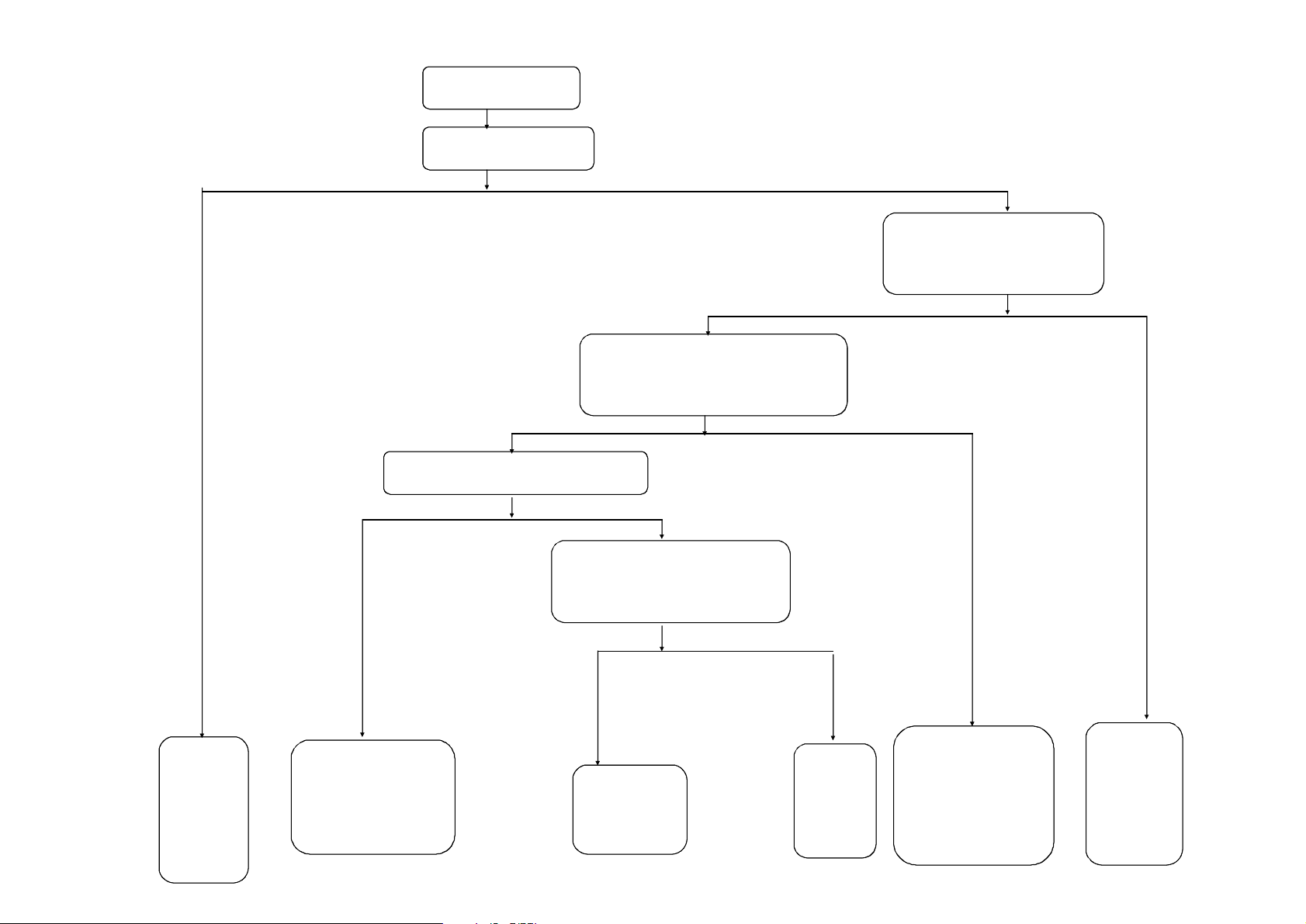
2.CV181H-B
Common problems solution
—Power Chart
—Power Units Problem Solving
—Display Units Problem Solving
—Audio Units Problem Solving
—Functional Units Problem Solving
Page 4
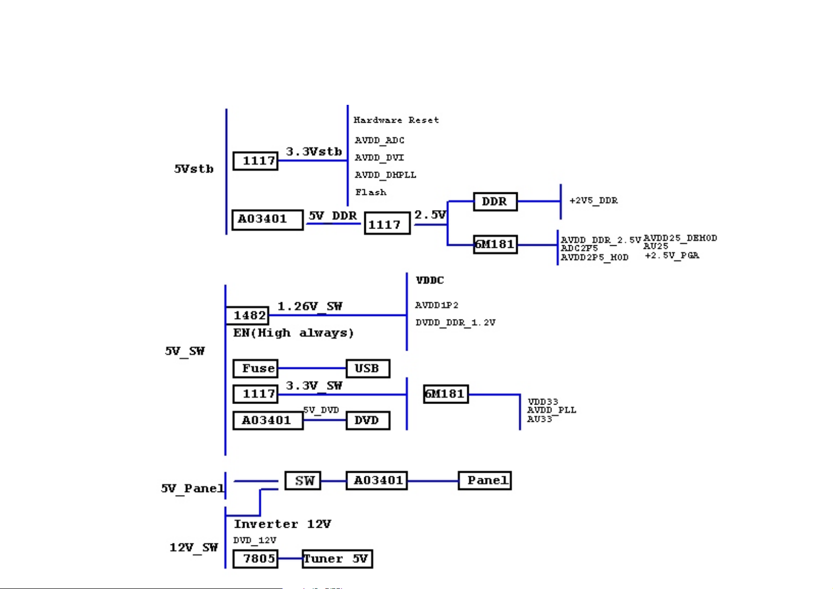
CV181H-B Power Chart
Page 5

2.1 Power Units Problem Solving(Mainboard can not boot.)
In stand-by condition,
Check TP1 Whether there is 5V?
Check external
power
N
Check main board TP7 have 3.3V ?
N Y
Check U9 Power
Supply Net
Check point Tp2 have 5V,
TP3 have 12V , Test point TP4 have
1.26V, Test point TP8 have 3.3V ,
Test point TP5 have 2.5V ?
Y
Normal boot
After power on,
Check the availability of shortcircuit power supply and
motherboard
Check power chip LDO (U4,U11)
work?Check power chip (U3)
work?
YN
OK
Page 6
2.2 Display Unit (black screen)
Change the LCD,
check if it is ok
Flickering or
Black screen(Back light on)
Check the connection of Driver
Board Cable connect well
N
Y
Change
LCD
N
Check the network output,
J5 cable socket
Works normal
Y
Check the software
match able
Y
Check U8 (MST6M181)
Power supply and clock
circuit chip LVDS output
pin is short circuit,
or open-circuit ?
N
Re-update the software
Check LCD power
VCC-Panel is OK ?
J4 voltage is ok?
Q2 output voltage is
ok ?
N
Change the circuit
Change driver
board cable
Page 7
2.3 Display Unit (black screen)
Black screen
Main board J6 5,6 pin
Have or not 12V?
Check the Inverter power supply
4pin of J6 output voltage is over 3.3V
N Y
Maintenance power
Y
N
Check power supply circuit
Inverter broke or
bad wire connection
Page 8
2.4 Audio Unit (no sound)
No sound
If Any audio signal input or
amplifier power supply normal
N
Check the Volume,
MUTE settings
Y
YN
CON3 If any signal output
Check
External audio
equipment
Ampl ifier p ower
supply circuit
Reset
Y
Check
external
Speaker
Check amplifier
power supply circuit
Power supply
normal change U2
N
Maintains U8
Peripheral
circuits,
change U8
N
U2(TPA3110D)3/12
Pin have signal input
NY
Check U8
audio input pin
has the signal output
Y
Check U2 & U8
Connect part
network
Page 9
N
2.5 Function Unit (ATV broke down)
TV no searching
/no image
Check External RF
signal input
Y
Check the Turner
NO.2,8pin of U5
Have 5V
Y
N
Check Tuner No. 6,7 pin of U5
Have I2C data
Check
external
RF
equipment
Check No.11,12 pin of U5
Y
Check U5&
U8(MST6M181)
connect network
Y
have IF signal
N
Check external circuit
of U5 is OK?
Y
Change
Tuner
N
Repair
its outer
circuit
N
Check pull-up
voltage of I2C
network is
Check
circuit of
U7
normal
Page 10

2.6 Function Unit (ATV with the image but no sound)
TV no sound only picture
Check the sound of PC& AV
N
Y
See “ NO SOUND ”
repair guide
Change
U8(MST6M181)
Page 11

2.7 Function Unit (PC)
PC
Image not
In the middle
Carry out
auto-adjust
operation
Color
U8(MST6M181)
R.G.B input signal
works well
Y N
Reset the
system settings
cast
Check VGA
circuit
connection
Check VGA
input circuit
Image
shakes
VS,HS signal
Stable and well
Y N
OSD settings,
Or input mode
not correct,
Reset it
Check VS.HS
Circuit
No signal
Check
VGA circuit
connection
Check VS.HS
Circuit
Page 12

2.8 Function (SCART,VGA)
SCART
Miss color,
color cast
U8(MST6M181)R.G.B
Input signal is normal
RGB、SCART
All no signal
Y N
The system is incorrect
re-set settings
Check SCART R.G.B
Input network
SCART socket
contact is ok
Check
U8
(MST6M181 )
Power supply
Page 13

2.9 Function Unit (HDMI)
HDMI
No image
U14( IT6633E )
HDMI and relevant
network
Y
Check the circuit of U14 and
U8(MST6M181) connect network
N
Check HDMI
and the input
network
Check HDMI
connection
Check If the sound
Y
Check HDMI and
input network
Image,
no sound
is ok in PC
N
See the repairs
guide “ No
Sound Solution”
Page 14

2.10 Function Unit (YPBPR)
YPBPR
YPBPR
Color cast
If have a dvd
Check U13 external circuit
Check U13
external circuit
Check video circuit of U13 and
U8(MST6M181) connect network
No signal
Check U8 external circuit
and crystal circuit.
Page 15

3.KEY BOARD AND REMOTE BOARD
3.1 KEY BOARD
View of copper SIDE(top/bottom)
3.2 REMOTE BOARD
View of copper SIDE(top/bottom)
Page 16

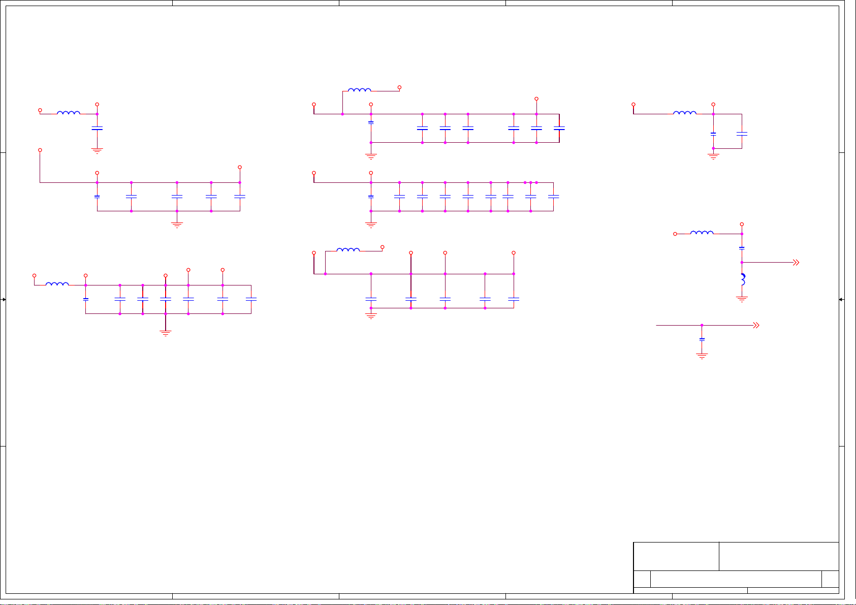
4.THE CIRCUIT
OF CV181H-D
Page 17

5
+5Vsb_IN
TP1
TP1
5Vsb_IN
5Vsb_IN
1
C36
1
+5V_SW
+5V_SW
C37
C37
470u/16V
470u/16V
C36
+
+
220u/16V
220u/16V
+12V_DC
+12V
TP2
TP2
12
C127
C127
220u/16V
220u/16V
TP3
TP3
+12V
+12V
1.26V_SW DC-DC
12VA
1
1 2
R34 100kR34 100k
<FUNCTION>
<FUNCTION>
TJC3-10A
TJC3-10A
D D
J3
J3
+5VSB
10
10
ON/OFF
9
9
8
8
7
7
6
6
5
5
4
4
3
3
2
2
1
1
+12V
PDP_5VSTB
+5V_SW
PDP_5V
12
C29
C29
C49
C49
C26
C26
100n
100n
100n
100n
100n
100n
1 2
C47
C47
3.3n
3.3n
R26
R26
3.6K
3.6K
C53 100nC53 100n
12
12
4
+5V_SW
600MA
C46
C46
100n
100n
1 2
L5
1 2
33uH/2.5AL533uH/2.5A
R220R22
U3
0
1 2
SYNC
EN
COMP
FB
VSW
GND
PAD
RT8295AU3RT8295A
1
BS
2
VIN
3
4
12
C51
C51
9
100n
100n
8
7
6
5
12
R21
R21
21K/1%
21K/1%
R20
R20
33K/1%
33K/1%
1 2
TP4
TP4
+1V2_SW
+1V2_SW
3
+1V2_SW
1
C52
C52
12
12
C58100n C58100n
470u/16V
470u/16V
C40
C40
100n
100n
12
2
1
PDP_5VSTB
R37
J1
TP8
TP8
+3V3_SW
C166
C166
100n
100n
12
+3V3_SW
+3V3_SW
50MA
1
12
C180
C180
12
C203
C203
100n
100n
100u/16V
100u/16V
TP7
TP7
+3V3
+3V3
3.3V_SW
+5V_SW
C201
C201
100n
100n
12
U11
U11
4
AMS1117-ADJ
AMS1117-ADJ
OUT
OUT
ADJ
ADJ
IN
300_1%
300_1%
2
1 2
1
R153
R153
499_1%
499_1%
1 2
R160
R160
3
IN
+5Vsb_IN
R110
R110
300_1%
300_1%
R109
R109
499_1%
499_1%
1 2
1 2
+3.3V_DC
U9
U9
3
IN
C C
C156
C156
100n
100n
12
4
AMS1117-ADJ
AMS1117-ADJ
OUT
OUT
ADJ
ADJ
IN
2
1
C154
C154
+
+
220u/16V
220u/16V
100MA
+3V3
1
C160
C160
100n
100n
12
3.3Vstb
+2.5V_LDO_SW
4
AMS1117-ADJ
AMS1117-ADJ
+2.5V_LDO_SW
U4
U4
IN
IN
OUT
OUT
ADJ
ADJ
3
2
1
R76 4.7kR76 4.7k
1 2
+5V_DDR
12
12
C63
C56
C56
B B
C63
100n
100n
10u
10u
PWR-ON/OFF
DDR Power (2.5V)
A A
5
+2.5V_LDO_SW
1
TP5
TP5
12
R24
R24
470/1%
470/1%
12
R23
R23
510/1%
510/1%
+5Vsb_IN
12
12
1
2 3
12
R77
R77
10k
10k
12
R58
R58
47k
47k
R61
R61
4.7k
4.7k
Q12
Q12
3904
3904
12
C45
C45
100n
100n
R57 100kR57 100k
1 2
+2V5
300MA
C54
C54
100u/16V
100u/16V
GV3407Q8GV3407
2
12
C86
C86
100n
100n
+5V_DDR
Q8
3
1
电源板on/off
+5Vsb_IN
R47
R47
4.7k
4.7k
PWR-ON/OFF
IO
口电阻拉高
1 2
PWR-ON/OFF7
4
R46 4.7k
R46 4.7k
1 2
+5Vsb_IN +5Vsb_IN
12
R43
R43
4.7K
4.7K
R42 1K_NC
R42 1K_NC
1 2
Q6
1
3904Q63904
R41 1K R41 1K
1 2
2 3
ON/OFF
12
R38
R38
4.7K
4.7K
ON/OFF
Q5
1
3904Q53904
2 3
3
J1
11
10
9
8
7
6
5
4
3
2
1
PH-11A_PDP
PH-11A_PDP
15V
12
C7
C7
100u/35V_PDP
100u/35V_PDP
DVD_EN
12
11
10
9
8
7
6
5
4
3
2
1
1
C8
100n_PDPC8100n_PDP
1 2
U1
U1
VIN
R74
R74
4.7K_NC
4.7K_NC
15V
15V
PDP_5V
PDP_5V
PDP_5VSTB
78D12_PDP
78D12_PDP
LM340
LM340
VOUT
GND
TAB
2
4
PDP_5VSTB
3
+5V_SW
1
ON/OFF
12VA
12
C23
C23
12
C24
C24
100n_PDP
100n_PDP
220u/16V_PDP
220u/16V_PDP
DVD_IR DVD_IR1
1 2
DVD_auto
DVD_stb
R69 100_NCR69 100_NC
R70 100_NCR70 100_NC
R71 100_NCR71 100_NC
12
R54
R54
4.7k_NC
4.7k_NC
R51 4.7k_NCR51 4.7k_NC
1 2
R45
R45
Q13
Q13
10k_NC
2 3
10k_NC
3904_NC
3904_NC
+3V3
+3V3
DVD_EN
DVD_auto
DVD_IR
DVD_stb
Size Document Number Rev
Size Document Number Rev
Size Document Number Rev
C
C
C
Date: Sheet
Date: Sheet
Date: Sheet
2
R39 4.7k_PDPR39 4.7k_PDP
1 2
5V_DVD+12V
12
12
C93
C93
22p_NC
22p_NC
+5V_SW
R48
R48
47k_NC
47k_NC
1
12
02.Power Supply
02.Power Supply
02.Power Supply
R40
R40
12
12
12
2 3
R37
47k_PDP
47k_PDP
1
12
12
C55
C55
10k_PDP
10k_PDP
100n_NC
100n_NC
DVD_AUTO1
DVD_STB1
12
12
C94
C94
22p_NC
22p_NC
Q9 GV3407_NCQ9 GV3407_NC
2
12
C76
C76
100N_NC
100N_NC
R52 100k_NCR52 100k_NC
1 2
R53
R53
4.7k_NC
4.7k_NC
Q7
3904_NCQ73904_NC
+3V3 3,7,8,10,11
GND 3,4,5,6,7,8,9,10,11,12
DVD_EN 7
DVD_auto 7
DVD_IR 7
DVD_stb 7
Title
Title
Title
CV181H-B
CV181H-B
CV181H-B
12
R36 100k_PDPR36 100k_PDP
1 2
12
R35
R35
4.7k_PDP
4.7k_PDP
Q4
3904_PDPQ43904_PDP
2 3
8
7
6
5
4
3
2
1
C95
C95
22p_NC
22p_NC
1
of
of
of
212Friday, June 24, 2011
212Friday, June 24, 2011
212Friday, June 24, 2011
PH-8A_NC
PH-8A_NC
8
7
6
5
4
3
2
1
J7
J7
3
12
C79
C79
100n_NC
100n_NC
Q1 GV3407_PDPQ1 GV3407_PDP
3
2
12
C50
C50
1
100N_PDP
100N_PDP
5V_DVD
11
11
11
12
C39
C39
100n_PDP
100n_PDP
12
D5 SK34B_PDPD5 SK34B_PDP
2 1
C38
C38
10u_PDP
10u_PDP
1
PDP_5V
Page 18

5
4
3
2
1
VGA INPUT
CON13 VGACON13 VGA
5
15
10
4
14
9
VGA-B
3
13
8
VGA-G
2
12
7
VGA-R
1
11
6
16
17
D D
DDC-SDAIN
DDC-SCLIN
D49
D49
D54
D54
ESD
ESD
ESD
ESD
PC Audio Input
PHONOJACK
PHONOJACK
CON7
CON7
C C
CON11
CON11
21
21
DATA2 SHIELD
DATA1 SHIELD
DATA0 SHIELD
22
22
23
23
DDC/CEC GND
20
HDMI
HDMI
CON12
CON12
21
21
HPD3
DDC3SCL
DDC3SDA
HPD1
DDC1SCL
DDC1SDA
22
23
20
21
22
23
20
DATA2 SHIELD
DATA1 SHIELD
DATA0 SHIELD
22
23
DDC/CEC GND
HDMI
HDMI
CON10
CON10
21
DATA2 SHIELD
DATA1 SHIELD
DATA0 SHIELD
22
23
DDC/CEC GND
HDMI
HDMI
B B
A A
VGA-HS
VGA-VS
DATA2+
DATA2-
DATA1+
DAT1A-
DATA0+
DATA0-
CLK SHIELD
+5V POWER
HOT PLUG1920
HPD2
DDC2SCL
DDC2SDA
DATA2+
DATA2-
DATA1+
DAT1A-
DATA0+
DATA0-
CLK SHIELD
+5V POWER
HOT PLUG1920
DATA2+
DATA2-
DATA1+
DAT1A-
DATA0+
DATA0-
CLK SHIELD
+5V POWER
HOT PLUG1920
1 2
GND
GND
CLK+
CLK-
CEC
SCL
SDA
CLK+
CLK-
CEC
SCL
SDA
CLK+
CLK-
CEC
SCL
SDA
R306 NCR306 NC
Audio_L
Audio_L
2
4
5
3
Audio_R
Audio_R
1
1
2
3
4
5
6
7
8
9
10
11
12
13
14
NC
15
16
17
18
1
2
3
4
5
6
7
8
9
10
11
12
13
14
NC
15
16
17
18
D50 ESDD50 ESD
D48 ESDD48 ESD
D47 ESDD47 ESD
1
2
3
4
5
6
7
8
9
10
11
12
13
14
NC
15
16
17
18
D28 ESDD28 ESD
D43 ESDD43 ESD
D42 ESDD42 ESD
5
1 2
PC_AUDIO_L
PC_AUDIO_R
CEC2
HPD2
D44 ESDD44 ESD
D46 ESDD46 ESD
D45 ESDD45 ESD
CEC3
HPD3
1 2
CEC1
HPD1
RXD
1 2
D30
D30
ESD
ESD
R285
R285
0
0
<FUNCTION>
<FUNCTION>
R2300R230
0
R302
R302
10k
10k
R2810R281
0
R288
R288
10k
10k
D29
D29
ESD
ESD
HDMI2
BHPD
R2451MR245
1M
HDMI3
AHPD
R2711MR271
1M
HDMI1
CHPD
R2321MR232
1M
R296 NC
R296 NC
1 2
R307 100R307 100
1 2
R295 100R295 100
1 2
R243 10kR243 10k
1 2
R244 10kR244 10k
1 2
R2743KR274
3K
TXD
<FUNCTION>
<FUNCTION>
12
12
12
D53
D53
D52
D52
ESD
ESD
ESD
ESD
TXD
RXD
12
12
R22812k R22812k
R22912k R22912k
DDC2SCL
DDC2SDA
R282
R282
1.5k
1.5k
BPWR5V
R2463KR246
3K
R270
R270
1.5k
1.5k
APWR5V
DDC1SCL
DDC1SDA DDC1BSDA
HDMI1_5V
R275
R275
1.5k
1.5k
CPWR5V
R2783KR278
3K
D51
D51
ESD
ESD
12
DDC3SCL
DDC3SDA
PC-BIN
PC-GIN
PC-RIN
C246
C246
C245
C245
C247
C247
10p
10p
10p
10p
10p
10p
R301 68R301 68
R287 0R287 0
HS_VGA
1 2
V_VGA
1 2
12
C248
C248
C239
C239
22p
22p
22p
22p
AIN2L
AIN2L 7
AIN2R
AIN2R 7
RX2B2P
RX2B2N
RX2B1P
RX2B1N
RX2B0P
RX2B0N
RX2BCLKP
RX2BCLKN
DDC2BSCL
R284 22R284 22
1 2
DDC2BSDA
R283 22R283 22
1 2
R247 4.7KR247 4.7K
1 2
R248 4.7KR248 4.7K
1 2
C237
C237
100n
100n
R273 22R273 22
1 2
R272 22R272 22
1 2
R240 4.7KR240 4.7K
12
R241 4.7KR241 4.7K
1 2
C238
C238
100n
100n
R269 22R269 22
1 2
R268 22R268 22
1 2
R237 4.7KR237 4.7K
12
R238 4.7KR238 4.7K
1 2
C235
C235
100n
100n
4
RX3B2P
RX3B2N
RX3B1P
RX3B1N
RX3B0P
RX3B0N
RX3BCLKP
RX3BCLKN
DDC3BSCL
DDC3BSDA
RX1B2P
RX1B2N
RX1B1P
RX1B1N
RX1B0P
RX1B0N
RX1BCLKP
RX1BCLKN
DDC1BSCL
BHPD
DDC2BSDA
DDC2BSCL
RX2BCLKN
RX2BCLKP
BPWR5V
RX2B0N
RX2B0P
RX2B1N
RX2B1P
RX2B2N
RX2B2P
APWR5V
AHPD
+3V3_SW
MI2C-SCL7,10
MI2C-SDA7,10
PC-GIN
PC-BIN
PC-RIN
J14
J14
1
2
3
4
PH-4A_NC
PH-4A_NC
C226
C226
2.2u/NC
2.2u/NC
1
BHPD
2
BSDA
3
BSCL
4
BRXCM
5
BRXCP
6
BRPWR5V
7
BRX0M
8
BRX0P
9
VSS2
10
BRX1M
11
BRX1P
12
VCC2
13
BRX2M
14
BRX2P
15
APWR5V
16
AHPD
+3V3_SW
C227
C227
10u
10u
R224
R224
10K
10K
1
2
3
4
12
12
1 2
12
12
12
R30075 R30075
R29975 R29975
R29875 R29875
RX1B2N
RX1B1P
RX1B2P
RX1B1N
62
64
60
63
61
VCC1
CRX1P
CRX2P
CRX2M
DIG_DBG/CEXT
IT6633E-P
IT6633E-P
ASDA18ASCL
ARXCM20ARXCP21VCC322ARX0M23ARX0P24VSS325ARX1M26ARX1P27ANA_DBG/NC28ARX2M29ARX2P30REXT
RESET
19
17
DDC3BSDA
RX3BCLKP
RX3BCLKN
DDC3BSCL
RESET_PS331
R178 68R178 68
1 2
R177 68R177 68
1 2
3
R305 33R305 33
1 2
R303 33R303 33
1 2
R304 33R304 33
1 2
+5Vsb_IN
D26
D26
ESD
ESD
RX1B0P
CPWR5V
RX1B0N
56
59
58
57
55
VSS1
CRX0P
CRX0M
CRX1M
RX3B0N
RX3B1N
RX3B0P
G_VGA
B_VGA
R_VGA
R223 33R223 33
RXD
12
TXD
12
R213 33R213 33
D27
D27
ESD
ESD
+3V3_SW
R190 NCR190 NC
1 2
RX1BCLKN
DDC1BSDA
DDC1BSCL
RX1BCLKP
CHPD
+3V3_SW
U14
U14
54
50
51
53
52
49
CSCL
CSDA
CHPD
CRXCP
CRXCM
CPWR5V
TXPWR5V
48
TXSDA
47
TXSCL
46
TXCM
45
TXCP
44
TXHPD
43
TX0M
42
TX0P
41
VSS4
40
TX1M
39
TX1P
38
VCC4
37
TX2M
36
TX2P
35
PCADR0
34
PCSCL
33
PCSDA
R204NCR204
NC/POWDN
NC
32
31
PCADR0
R207
R207
Control of serial programming device address:
‘0’: 0x94
510/1%
510/1%
‘1’: 0x96
RX3B1P
RX3B2N
RX3B2P
(default to ‘0’: 0x94 by internal weak pulled-down resistor of
100kΩ)
IT6633_SCL
IT6633_SDA
CEC1
CEC2
CEC3
G_VGA 5
B_VGA 5
R_VGA 5
C220
C220
C222
C222
100n
100n
100n
100n
+5V_HDMI
R179
R179
100K_NC
100K_NC
1 2
R1924.7K R1924.7K
R1914.7K R1914.7K
W/S= 9/11 mil
SDA_HDMI
R162 22R162 22
SCL_HDMI
R163 22R163 22
RXCM
RXCP
HPD_HDMI
R193 22R193 22
RXM0
RXP0
RXM1
RXP1
RXM2
RXP2
IT6633_SCL
IT6633_SDA
R203
R203
R188NCR188
R189NCR189
4.7K
4.7K
NC
NC
+3V3_SW
HDMI CEC
2
V_VGA
HS_VGA
TXD
RXD
C234
C234
100n
100n
HDMI SWITCH
SDA_HDMI
SCL_HDMI
CEC_HDMI
RXCM
RXCP
RXM0
RXP0
RXM1
RXP1
RXM2
RXP2
HPD_HDMI7
IP6633P device address:
PCADR0=‘0’: 0x94
PCADR0=‘1’: 0x96
R286 220R286 220
CEC_HDMICEC
C231
C231
D41
D41
22p
22p
ESD
ESD
Size Document Number Rev
Size Document Number Rev
Size Document Number Rev
Custom
Custom
Custom
Date: Sheet
Date: Sheet
Date: Sheet
SDA_HDMI 7
SCL_HDMI 7
CEC_HDMI 7
RXCM 7
RXCP 7
RXM0 7
RXP0 7
RXM1 7
RXP1 7
RXM2 7
RXP2 7
HPD_HDMI
03.PC/HDMI
03.PC/HDMI
03.PC/HDMI
V_VGA 5
HS_VGA 7
TXD 7
RXD 7
Title
Title
Title
1
CV181H-B
CV181H-B
CV181H-B
312Friday, June 24, 2011
312Friday, June 24, 2011
312Friday, June 24, 2011
of
of
of
11
11
11
Page 19

5
SCART1 Input
CON8
CON8
VIN
VIN
GNDVI
GNDVI
RGBSW
RGBSW
GNDSW
GNDSW
N.C.
N.C.
N.C.
N.C.
FunSel
FunSel
AIL
AIL
GNDA
GNDA
AIR
AIR
12
R254 10kR254 10k
R259 10kR259 10k
Q26 3904Q26 3904
Q27 3904Q27 3904
2 3
21
20
19
18
17
16
15
14
13
12
11
10
9
8
7
6
5
4
3
2
1
D38
D38
ESD_NC
ESD_NC
1 2
1 2
1
2 3
1
R277 4.7KR277 4.7K
SC1_CVBS_IN
SC1_CVBS_OUT
SC1_FB
SC1_RIN
SC1_GIN
SC1_FS
SC1_BIN
SC1_AU_LIN
SC1_AU_LOUT
SC1_AU_RIN
SC1_AU_ROUT
D37
D37
D39
D39
ESD_NC
ESD_NC
ESD_NC
ESD_NC
R25312k R25312k
1 2
C1981u C1981u
12
C1971u C1971u
12
1 2
R279 4.7KR279 4.7K
1 2
D35
D35
ESD_NC
ESD_NC
1 2
R26012k R26012k
AIN1L
AIN1R
C168220p C168220p
R150200k R150200k
PWD_MT
SHILED
SHILED
VOUT
VOUT
GNDVO
GNDVO
RIN
RIN
GNDR
SC1_AU_LOUT
SC1_AU_ROUT
C232
C232
C233
C233
22n
22n
22n
22n
GNDR
GIN
GIN
GNDG
GNDG
BIN
BIN
GNDB
GNDB
AOL
AOL
AOR
AOR
SCART
SCART
SC1_AU_LIN
SC1_AU_RIN
12
D D
C C
FS -> SOY1 / SARIN1 / SOY2 / SARIN2
0-2v: TV Mode -> 0-0.33v
5-8v: 16:9 AV -> 0.83-1.33v
9.5-12v: 4:3 AV -> 1.58-2.0v
D31
D31
D34
D34
D55
D55
ESD_NC
ESD_NC
ESD_NC
ESD_NC
ESD_NC
ESD_NC
AOUT1L
AOUT1R
12
12
R145200k R145200k
C163220p C163220p
1 2
1 2
PWD_MT
1 2
R252 10kR252 10k
SC1_GIN
SC1_RIN
SC1_BIN
D36
D36
D32
D32
ESD_NC
ESD_NC
ESD_NC
ESD_NC
D33
D33
ESD_NC
ESD_NC
4
CVBS1_INSC1_CVBS_IN
R29775R297
R292 NCR292 NC
1 2
R258 NCR258 NC
1 2
R289 NCR289 NC
1 2
R291 NCR291 NC
1 2
R290 NCR290 NC
1 2
R308 NCR308 NC
1 2
75
1 2
Y1_IN
PR1_IN
PB1_IN
SC1_AU_RIN
SC1_AU_ROUT
SC1_AU_LIN
SC1_AU_LOUT
SC1_CVBS_OUT
SC1_CVBS_IN
SOY1_IN
SAR2
ADC2
R251
R251
R25775R257
2.2k
2.2k
75
1 2
1 2
12
R25675 R25675
口控制
12
12
R25075 R25075
R29475 R29475
CON9
CON9
NC_AV3-8R4-5
NC_AV3-8R4-5
L
L
R
R
V
V
SOY1_IN 5
R249 33R249 33
1 2
R293 33R293 33
1 2
R255 33R255 33
1 2
6
5
4
3
2
1
3
DVD Signal input
J13
J13
1
1
2
2
3
3
4
4
5
5
6
6
PH-6A_NC
PH-6A_NC
YPbPr SWITCH
C210 470N_NCC210 470N_NC
YPbPr_Y
C217 470N_NCC217 470N_NC
1 2
1 2
C215 470N_NCC215 470N_NC
C208 470N_NCC208 470N_NC
1 2
1 2
C218 470N_NCC218 470N_NC
C216 470N_NCC216 470N_NC
1 2
1 2
1 2
R186 100R186 100
SWITCH7
DVD_Y
YPbPr_Pb
DVD_Pb
YPbPr_Pr
DVD_Pr
2
D18
D18
ESD_NC
ESD_NC
ESD_NC D20ESD_NC D20
ESD_NC D23ESD_NC D23
YPbPr_Yin
YPbPr_Pbin
YPbPr_Prin
R214470K_NC R214470K_NC
R183470K_NC R183470K_NC
VCC
GND
R181470K_NC R181470K_NC
1A
2A
3A
4A
R156 10K_NCR156 10K_NC
1 2
R157 10K_NCR157 10K_NC
1 2
D19
D19
ESD_NC
ESD_NC
12
12
12
+5V_SW
+5V_SW
16
YPbPr_Yin
4
YPbPr_Pbin
7
YPbPr_Prin
9
12
8
R20975_NC R20975_NC
C224
C224
10u_NC
10u_NC
R167 33R167 33
J12
J12
1
2
3
PH-3A_NC
PH-3A_NC
DVD_Pb
DVD_Pr
DVD_Y
V_CLAMP1
12
12
12
12
12
1
2
3
YPbPr_Y
YPbPr_Pb
YPbPr_Pr
12
DVD_L
DVD_R
ESD_NC D25ESD_NC D25
R196 0R196 0
R206 0R206 0
1 2
R208 0R208 0
1 2
1 2
R184470K_NC R184470K_NC
R215470K_NC R215470K_NC
R182470K_NC R182470K_NC
2
1B1
3
1B2
5
2B1
6
2B2
11
3B1
10
3B2
14
4B1
13
4B2
1
S
15
OE
U13 PI5V330S_NCU13 PI5V330S_NC
R151
R151
12K_NC
12K_NC
1 2
R20275_NC R20275_NC
R18075_NC R18075_NC
R216 47k_NCR216 47k_NC
1 2
12
12
R168 33R168 33
1 2
R166 33R166 33
1 2
R170 33R170 33
1 2
1 2
1
AIN3L
AIN3R
1 2
DVD_Pr
DVD_Pb
DVD_Y
C221
C221
100n_NC
100n_NC
R152
R152
12K_NC
12K_NC
12
R210
R210
47k_NC
47k_NC
C188 47nC188 47n
1 2
C186 47nC186 47n
1 2
C190 47nC190 47n
1 2
C187 1nC187 1n
1 2
V_CLAMP1
12
C219
C219
100n_NC
100n_NC
12
Y2_IN
PB2_IN
PR2_IN
SOY2_IN
C202
C202
10u_NC
10u_NC
Av & YPbPr
CON4
CON4
AV3-8R4-5
B B
A A
AV3-8R4-5
L
L
R
R
V
V
CON6
CON6
AV3-8R4-5
AV3-8R4-5
L
L
R
R
V
V
AV1-R
6
5
AV1-L
4
3
AV1-CVBS
2
1
HD1_Pr
6
5
HD1_Pb
4
3
HD1_Y
2
1
These components close to MST6M181
AV1-L AIN0L
AV1-R
AV1-CVBS
ESD D9ESD D9
ESD D11ESD D11
ESD D6ESD D6
HD1_Pr
HD1_Pb
HD1_Y
ESD D21ESD D21
R87 10kR87 10k
1 2
1 2
R75 10kR75 10k
12
R11275 R11275
ESD D22ESD D22
ESD D24ESD D24
R7912k R7912k
12
12
12
12
R9512k R9512k
YPbPr_Pr
YPbPr_Pb
YPbPr_Y
R18575 R18575
R20575 R20575
R19575 R19575
Audio in off page
AIN0R
CVBS3_IN
12
AIN3L
AIN3R
AIN0L
AIN0R
Video out off page
CVBS3_IN
Y2_IN7
SOY2_IN7
PB2_IN7
PR2_IN7
In page
AOUT1L7
AOUT1R7
CVBS2_IN7
C2_IN7
AIN3L 7
AIN3R 7
AIN0L 7
AIN0R 7
CVBS3_IN 7
Y2_IN
SOY2_IN
PB2_IN
PR2_IN
AOUT1L
AOUT1R
CVBS2_IN
C2_IN
Size Document Number Rev
Size Document Number Rev
Size Document Number Rev
Custom
Custom
Custom
Date: Sheet of
Date: Sheet of
Date: Sheet of
Video out off page
CVBS1_IN
Y1_IN5
PB1_IN5
PR1_IN5
CVBS1_IN 7
Y1_IN
PB1_IN
PR1_IN
Audio off page
AIN1L
AIN1R
AOUT1L
AOUT1R
Control Pin off page
In page
SC1_CVBS_OUT5
Title
Title
Title
04.Input Video/Audio
04.Input Video/Audio
04.Input Video/Audio
SAR2
SC1_CVBS_OUT
CV181H-B
CV181H-B
CV181H-B
AIN1L 7
AIN1R 7
AOUT1L 7
AOUT1R 7
SAR2 7
412Friday, June 24, 2011
412Friday, June 24, 2011
412Friday, June 24, 2011
11
11
11
5
4
3
2
1
Page 20

5
D
C
B
A
A
4
3
2
1
PI5V330
+5V_SW
D
B_VGA
R_VGA
C243 470nC243 470n
C225 470nC225 470n
1 2
1 2
C242 470nC242 470n
C223 470nC223 470n
1 2
1 2
C244 470nC244 470n
C240 470nC240 470n
1 2
1 2
R211 0R211 0
1 2
VCC_3V3
G_VGA
Y1_IN
B_VGA
PB1_IN
R_VGA
C
PR1_IN
V_VGA
SOY1_IN
G_VGA
Y1_IN
PB1_IN
PR1_IN
V_VGA
SOY1_IN
AUDIO_SEL
1 2
R72
R72
10k
10k
12
12
12
1 2
R219 100R219 100
C230
C230
10u
10u
12
R236 47kR236 47k
1 2
V_CLAMP2
12
12
12
V_CLAMP2
12
R263
R263
47k
47k
12
R225470k R225470k
R235NC R235NC
12
R262470k R262470k
12
C241
C241
10u
10u
C236
C236
100n
100n
R264470k R264470k
R276470k R276470k
R239470k R239470k
R280470k R280470k
PI5V330S
PI5V330S
U15
U15
2
1B1
3
1B2
5
2B1
6
2B2
11
3B1
10
3B2
14
4B1
13
4B2
1
S
15
OE
VCC
GND
16
4
1A
7
2A
9
3A
12
4A
8
+5V_SW
R200 33R200 33
1 2
R199 33R199 33
1 2
R165 33R165 33
1 2
R164 33R164 33
1 2
C212 47nC212 47n
1 2
C211 47nC211 47n
1 2
C185 47nC185 47n
1 2
C184 1nC184 1n
1 2
R217 68R217 68
1 2
G_IN
B_IN
R_IN
SOG_IN
VS_VGA
+5V_SW
These components close to MST6M181
USB Input
1.5AF11.5A
F1
1 2
100u/16V
100u/16V
+5V_SW
1.5A_NCF21.5A_NC
F2
1 2
10u_NC
10u_NC
C120
C120
+5V_USB1
C21
C21
+
+
+5V_USB2
12
12
C20
C20
100n
100n
12
C122
C122
100n_NC
100n_NC
+5V_USB1
DVBDM
DVBDP
DVBDM1
DVBDP1
12
12
R6 5.1RR6 5.1R
R5 5.1RR5 5.1R
D1
ESDD1ESD
12
12
R108 5.1R_NCR108 5.1R_NC
R111 5.1R_NCR111 5.1R_NC
ESDD2ESD
D2
USB_DM1
USB_DP1
USB_DM
USB_DP
CON2
CON2
1
1
2
2
3
3
4
4
5
5
6
6
USB
USB
CON5
CON5
1
1
2
2
3
3
4
4
PH-4A_NC
PH-4A_NC
D10
D10
ESD
SOG_IN
B_IN
G_IN
R_IN
VS_VGA
Title
Title
Title
ESD
High (1-3V) - RGB / Low (0-0.4V) - Composite
B
SW_GAIN7
SCART_AVOUT
12
R85
R85
4.7k
4.7k
R261 4.7kR261 4.7k
1 2
C228 10u/16VC228 10u/16V
1
2 3
CVBSOut17
VCC_3V3
SW_GAIN
5
Q23
Q23
3904
3904
12
1
+5V_SW
C229
C229
100n
100n
1 2
R233 15kR233 15k
1 2
R267 10R267 10
1 2
2 3
Q25
Q25
3904
3904
DVBDM
DVBDP
DVBDM1
DVBDP1
CVBSOut1
R221
R221
47k
47k
1 2
R234
R234
33k
33k
1 2
R222
R222
330
330
Q24
Q24
R265 150R265 150
1
3906
3906
3 2
R266 75R266 75
12
SC1_CVBS_OUT
12
D40D40
21
3
SC1_CVBS_OUT 4
2
1 2
Q22
Q22
1
3904
3904
R226 10R226 10
1 2
2 3
R227
R227
150
150
1 2
4
DVBDM 7
DVBDP 7
DVBDM1 5
DVBDP1 5
CVBSOut1 7
Size Document Number Rev
Size Document Number Rev
Size Document Number Rev
Custom
Custom
Custom
Date: Sheet
Date: Sheet
Date: Sheet
05.Input USB/SCART SWITCH
05.Input USB/SCART SWITCH
05.Input USB/SCART SWITCH
D12
D12
ESD
ESD
SOG_IN 7
B_IN 7
G_IN 7
R_IN 7
VS_VGA 7
CV181H-B
CV181H-B
CV181H-B
of
of
of
512Friday, June 24, 2011
512Friday, June 24, 2011
512Friday, June 24, 2011
1
11
11
11
Page 21

D D
+12V
U7
U7
1
VIN
GND
12
C C
16
IF OUT2
11
B B
12
IF_OUT1
IF_OUT2
TU_SDA
TU_SCL
2
C125
C125
100n
100n
GND113GND214GND315GND4
U5
U5
F33WT-3DDR-E
F33WT-3DDR-E
NC1VCC_5V_A2RF_AGC3BT_NC14AS5SCL6SDA7VCC_5V_B8ADC9BT_NC210IF OUT1
+5V_IN_TUNER
TUAGC
+5V_IN_TUNER
7805
7805
LM340
LM340
VOUT
TAB
4
3
470u/16V
470u/16V
+5V_IN_TUNER
C111
C111
TUAGC
TU_SDA
TU_SCL
TP6
TP6
1
12
IF_OUT2
IF_OUT1
12
C98
C98
100n
100n
1 2
+5V_IN_TUNER+5V_IN_TUNER
C96
C96
C116
C116
100n
100n
100n
100n
12
12
C102 100nC102 100n
1 2
C101 100nC101 100n
1 2
C99
C99
22p
22p
R64 100R64 100
1 2
1 2
R67 68R67 68
1 2
R68 68R68 68
C100
C100
22p
22p
L90L9
0
L80L8
0
TAGC
TAGC
TUNER_SDA
TUNER_SCL
C133NCC133
12
C117 0C117 0
1 2
L14 NCL14 NC
C108
C108
1 2
L10 NCL10
NC
NCNC
L11 NCL11 NC
C110 0C110 0
1 2
C124 33C124 33
1 2
L15 NCL15 NC
L12 NCL12 NC
C121 33C121 33
1 2
33
NC
C129
C129
220p
220p
C126NCC126
12
12
NC
R103 51R103 51
1 2
L16
L16
Q值:15(MIN)
100nH
100nH
1 2
R102 51R102 51
C132 100nC132 100n
1 2
1 2
C128 100nC128 100n
VIFM 7
VIFP 7
欧
12
12
C97
C97
100n
100n
Title
Title
Title
CV181H-B
CV181H-B
CV181H-B
Size Document Number Rev
Size Document Number Rev
Size Document Number Rev
Custom
Custom
Custom
Date: Sheet of
Date: Sheet of
Date: Sheet of
A A
5 4 3 2 1
06.IF-Tuner
06.IF-Tuner
06.IF-Tuner
6 12Friday, June 24, 2011
6 12Friday, June 24, 2011
6 12Friday, June 24, 2011
11
11
11
Page 22

5
4
3
2
1
USB Input
DVBDM
+5Vsb_IN
12
12
RXD
RXD3
TXD
TXD3
D D
SPI Flash
SD1_FLASH10
SD0_FLASH10
CEN_FLASH10
SCK_FLASH10
SD1_FLASH
SD0_FLASH
CEN_FLASH
SCK_FLASH
MI2C-SCL
MI2C-SCL3,10
MI2C-SDA
MI2C-SDA3,10
D-Sub
HS_VGA3
VS_VGA5
B_IN5
G_IN5
R_IN5
Video Input
C C
SOG_IN5
YPBPR
Y2_IN4
SOY2_IN4
PB2_IN4
PR2_IN4
CVBS Input
CVBS1_IN4
CVBS2_IN4
CVBS3_IN4
Audio Input
AIN0L4
AIN0R4
AIN1L4
BL_ADJ
R50
R50
4.7K
4.7K
AIN1R4
AIN2L3
AIN2R3
AIN3L4
AIN3R4
Audio Input
B B
VCC_3V3
12
VCC_3V3
VCC_3V3
12
PANEL_ON/OFF11
A A
R81
R81
10k
10k
DVD_auto
R84 10kR84 10k
1 2
R80 10kR80 10k
1 2
R101
R101
10k
10k
SWITCH
BL_ADJ11
BL_ON11
STB_AMP12
SWITCH12
VCC_3V3
12
R73
R73
10k
10k
DVD_EN
DVD_stb
DVD_IR
12
PANEL_ON/OFF
BL_ADJ
BL_ON
STB_AMP XTALO
SWITCH
R218
R218
4.7K
4.7K
C2_IN4
SDA_HDMI3
SCL_HDMI3
CEC_HDMI3
HPD_HDMI3
RXCM3
RXCP3
RXM03
RXP03
RXM13
RXP13
RXM23
RXP23
HDMI
AIN0L
AIN0R
AIN1L
AIN1R
AIN2L
AIN2R
AIN3L
AIN3R
R220
R220
4.7K
4.7K
HS_VGA
VS_VGA
B_IN
G_IN
R_IN
SOG_IN
Y2_IN
SOY2_IN
PB2_IN
PR2_IN
CVBS1_IN
CVBS2_IN
C2_IN
CVBS3_IN
SDA_HDMI
SCL_HDMI
CEC_HDMI
HPD_HDMI
RXCM
RXCP
RXM0
RXP0
RXM1
RXP1
RXM2
RXP2
CVBS1_IN
CVBS3_IN
CVBSOut1
Close to IC
L22FBL22
with width trace
FB
1 2
DVBDM5
DVBDP5
DVBDM15
DVBDP15
SARADC Input
KEY0-SAR010
KEY1-SAR110
LED10
IRIN10
System-RST10
Flash_wp10
SAR24
IRIN
CEC_HDMI
System-RST
HPD_HDMI
RXCM
RXCP
RXM0
RXP0
AVDD_DVI
RXM1
RXP1
SDA_HDMI
RXM2
RXP2
SCL_HDMI
VDDC
12
R201 68R201 68
R171 33R171 33
R172 33R172 33
R173 33R173 33
R174 33R174 33
R175 33R175 33
R176 68R176 68
C21347n C21347n
1 2
AVDD1P2
ADC2P5
R169 68R169 68
C189 47nC189 47n
1 2
AVDD_ADC
C191 47nC191 47n
1 2
C192 47nC192 47n
1 2
C193 47nC193 47n
1 2
C194 47nC194 47n
1 2
C195 47nC195 47n
1 2
C196 47nC196 47n
1 2
CVBSOut1
AIN0L
AIN0R AUR0
AIN1R
C178
C178
C177
C177
C183
C183
100n
100n
100n
100n
10u
10u
TAGC
TAGC
C119
C119
22n
22n
DVBDP
DVBDM1
DVBDP1
KEY0-SAR0
KEY1-SAR1
LED
IRIN
System-RST
Flash_wp
SAR2
1
2
3
4
5
6
7
8
9
10
11
12
13
14
15
16
17
18
19
20
21
22
23
HS_VGA
B_IN
SOG_IN
G_IN
R_IN
VS_VGA
PB2_IN
SOY2_IN
Y2_IN
PR2_IN
CVBS4P
CVBS3P
CVBS2P
CVBS1P
CVBS0P
VCOM0
AUL0
C2051u C2051u
C2061u C2061u
AUL1
C2041u C2041u
AUR1
C2071u C2071u
AUVRM
AUVRP
AUVAG
12
AU25
C182
C182
10u
10u
R97 10K
R97 10K
24
25
26
27
28
29
30
31
32
33
34
35
36
37
38
39
40
41
42
43
44
45
46
47
48
49
50
51
52
53
54
+5V_IN_TUNER
12
R100
R100
10K
10K
AGC
12
Close MST6M181VS
R23168R231
R21268R212
R242
R242
68
68
0
0
KEY0-SAR0
CEN_FLASH
SD0_FLASH
205
206
207
SPI_CZ
SPI_DO
GPIO11/SAR0
AOUT2R
AVDD_DVI
DVBDP1
SCK_FLASH
SD1_FLASH
DVDD_NODIE_1.2V
200
201
202
203
204
199
SPI_DI
SPI_CK
GND_EFUSE
AVDD_NODIE
DVDD_NODIE
MST6M181VS
MST6M181VS
XTALI
XTALO
AVSS_PGA
AVDD_DMPLL
AVDD25_DEMOD
DP_P1
PWR-ON/OFF
STB_AMP
SAR2
RXD
TXD
12
12
12
LED
PWR-ON/OFF
Flash_wp
KEY1-SAR1
BL_ON
STB_AMP
U8
U8
216
263
E-pad
IRIN
CEC
RESET
HOTPLUGA
RXCN
RXCP
RX0N
RX0P
AVDD_DVI_3.3V
RX1N
RX1P
DDCDA_DA
RX2N
RX2P
DDCDA_CK
ARC
NC1
NC2
NC3
NC4
NC5
NC6
NC7
VDDC
HSYNC0
BIN0P
SOGIN0
GIN0P
GIN0M
RIN0P
VSYNC0
AVDD1P2
AVDD2P5_ADC
BIN1P
SOGIN1
GIN1P
GIN1M
RIN1P
AVDD3P3_ADC
CVBS4
CVBS3
CVBS2
CVBS1
CVBS0
VCOM
CVBS_OUT1
LINEIN_L0
LINEIN_R0
LINEIN_L1
LINEIN_R1
VRM
VRP
VAG
AVDD_AU25
LINEIN_L355LINEIN_R356LINEIN_L457LINEIN_R458LINEIN_L559LINEIN_R560AVDD_AU3361LINEOUT_L362LINEOUT_R363LINEOUT_L064LINEOUT_R065NC866NC967NC1068XTAL_IN69XTAL_OUT70AVDD_DMPLL71AVDD25_REF72AVSS_PGA73VIFM74VIFP75AVDD25_PGA76SIFP77SIFM78TAGC79GPIO22/I2S_OUT_WS/RX280GPIO23/I2S_OUT_SD/TX281GPIO24/TUNER_SCL82GPIO25/TUNER_SDA83GPIO26/SPDIF_IN/RX1/PWM384GPIO27/SPDIF_OUT85VDDC86VDDP_187GPIO2888GPIO30/I2S_OUT_MCK89GPIO32/I2S_OUT_BCK90GPIO3691GPIO3792GPIO3893GPIO4594GPIO4795GPIO4996NC1197B_ODD0/RXE4+98B_ODD1/RXE4-99B_ODD2/RXE3+
C2001uC200
C1651uC165
C1991uC199
1u
1u
1u
AIN2L
AIN2R
208
209
211
212
213
214
215
210
DDCA_CK
DDCA_DA
GPIO12/SAR1
GPIO13/SAR2
GPIO6/PM1/TX
GPIO8/PM5/RX
GPIO9/PM6/CS1
GPIO10/PMGPIO
GPIO7/PM4/POWER_ON
C1611uC161
1u
AOUT1R
AOUT2L
AOUT1L
AIN3L
AIN3R
AU33
DVBDM1
198
VIFM
DM_P1
VIFM
DVBDP
197
DP_P0
VIFP
VIFP
DVBDM
195
196
DM_P0
SIFP
+2.5V_PGA
MI2C-SCL
194
TESTPIN
SIFM
SIFP
SIFM
VDD33
MI2C-SDA
192
193
VDDP_3
DDCR_DA
DDCR_CK
AGC
SWITCH
VDDC
MA4
191
190
VDDC
SIF_CTL
TUNER_SCL
MA5
MA7
MA6
187
188
189
A_DDR1_A6
A_DDR1_A5
A_DDR1_A4
TUNER_SDA
SPDF_OUT
Audio Output
These components close to MST6M181
12
C146 33pC146 33p
3
C145 33pC145 33p
1 2
24MHzX124MHz
1 2
X1
XTALI
R1181MR118
1M
1 2
AVDD_DDR_2.5V
MA9
MA8
184
185
186
A_DDR1_A8
A_DDR1_A7
AVDDIO_2.5V
PANEL_ON/OFF
VDD33
VDDC_86
MA11
MA12
A-MCKE
181
182
183
A_DDR1_A9
A_DDR1_A12
A_DDR1_A11
SW_GAIN
AUBCK_OUT
AUMCK_OUT
PANEL_ON/OFF
AVDD_DDR_2.5V
AVDD_DDR_2.5V
A_MCLK
A_MCLKZ
MD14
MD15
173
174
175
176
177
178
179NC180
A_MVREF
AVDDIO_2.5V
AVDDIO_2.5V
A_DDR1_CKE
A_DDR1_DQ14
A_DDR1_DQ15
A_DDR1_MCLK
A_DDR1_MCLKZ
GPIO77/I2S_OUT_MUTE/PWM3/LVSYNC
LVRXE4+
LVRXE4-
DVD_auto
DVD_stb
DVD_IR
DVD_EN
AUDIO_SEL
AUDIO_SEL
AVDD_DDR_2.5V
AVDD_PLL
A_MDQMU
A_MDQSU
MD8
MD9
MD11
MD10
MD12
MD13
163
164
165
168
169
170
171
172
166
167
UDQS0
UDQM0
AVDD_PLL
AVDDIO_2.5V
A_DDR1_DQ8
A_DDR1_DQ9
A_DDR1_DQ10
A_DDR1_DQ11
A_DDR1_DQ12
A_DDR1_DQ13
GPIO76/I2S_IN_BCK/PWM2/LHSYNC
GPIO74/I2S_IN_WS/PWM4/RX3/LCK
100
LVRXE3+
DVDD_DDR_1.2V
LDQM0
LDQS0
AVDDIO_2.5V
A_DDR1_DQ7
A_DDR1_DQ6
A_DDR1_DQ5
AVDDIO_2.5V
A_DDR1_DQ4
A_DDR1_DQ3
A_DDR1_DQ2
A_DDR1_DQ1
AVDDIO_2.5V
A_DDR1_DQ0
A_DDR1_WEZ
A_DDR1_CAS
A_DDR1_RAS
A_DDR1_BA0
AVDDIO_2.5V
A_DDR1_BA1
A_DDR1_A10
A_DDR1_A0
A_DDR1_A1
A_DDR1_A2
A_DDR1_A3
GPIO21/PWM1
GPIO20/PWM0
VDDP_2
GPIO75/I2S_IN_SD/PWM5/TX3/LDE
B_ODD3/RXE3-
B_ODD4/RXEC+
101
102
LVRXEC+
LVRXE3-
SW_GAIN7
AVDD_LPLL
AVDD2P5_MOD
R_ODD7/RXO0-
R_ODD6/RXO0+
R_ODD5/RXO1-
R_ODD4/RXO1+
R_ODD3/RXO2-
R_ODD2/RXO2+
R_ODD1/RXOC-
R_ODD0/RXOC+
G_ODD7/RXO3G_ODD6/RXO3+
G_ODD5/RXO4G_ODD4/RXO4+
G_ODD3/RXE0G_ODD2/RXE0+
B_ODD5/RXEC-
B_ODD6/RXE2+
B_ODD7/RXE2-
G_ODD0/RXE1+
G_ODD1/RXE1-
AVDD2P5_MOD
103
104
105
106
107
108
LVRXEC-
LVRXE1-
LVRXE2-
LVRXE1+
LVRXE2+
AVDD2P5_MOD
SW_GAIN
12
12
R88
R88
R44
R44
4.7K
4.7K
4.7K
4.7K
NC15
NC14
NC13
NC12
VDDC
VDDC
162
161
160
159
158
157
156
155
154
153
152
151
150
149
148
147
146
145
144
143
142
141
140
139
138
137
136
135
134
133
132
131
130
129
128
127
126
125
124
123
122
121
120
119
118
117
116
115
114
113
112
111
110
109
A_MDQML
A_MDQSL
MD7
MD6
MD5
MD4
MD3
MD2
MD1
MD0
A-MWEZ
A-MCASZ
A-MRASZ
A-MBADR0
A-MBADR1
MA10
MA0
MA1
MA2
MA3
CFG-PWM1
BL_ADJ
LVRXO0LVRXO0+
LVRXO1LVRXO1+
LVRXO2LVRXO2+
LVRXOCLVRXOC+
LVRXO3LVRXO3+
LVRXO4LVRXO4+
LVRXE0LVRXE0+
DVDD_DDR_1.2V
AVDD_DDR_2.5V
AVDD_DDR_2.5V
AVDD_DDR_2.5V
AVDD_DDR_2.5V
VDDC
VDD33
AVDD_PLL
AVDD2P5_MOD
VDDC
Memory
LVRXO0- TX0M0
LVRXO0+ TX0P0
LVRXO1- TX0M1
LVRXO1+ TX0P1
LVRXO2- TX0M2
LVRXO2+ TX0P2
LVRXOC- TXCLK0M
LVRXOC+ TXCLK0PAIN1L
LVRXO3- TX0M3
LVRXO3+ TX0P3
LVRXO4- TX0M4
LVRXO4+ TX0P4
LVRXE0- TX1M0
LVRXE0+ TX1P0
LVRXE1- TX1M1
LVRXE1+ TX1P1
LVRXE2- TX1M2
LVRXE2+ TX1P2
LVRXEC- TXCLK1M
LVRXEC+ TXCLK1P
LVRXE3- TX1M3
LVRXE3+ TX1P3
LVRXE4- TX1M4
LVRXE4+ TX1P4
SPDF_OUT
MA[0..12]
MD[0..15]
A-MBADR0
A-MBADR1
A-MWEZ
A-MCASZ
A-MRASZ
A_MDQSL
A_MDQML
A_MDQMU
A_MDQSU
A-MCKE
A_MCLK
A_MCLKZ
TX0M0
TX0P0
TX0M1
TX0P1
TX0M2
TX0P2
TXCLK0M
TXCLK0P
TX0M3
TX0P3
TX0M4
TX0P4
TX1M0
TX1P0
TX1M1
TX1P1
TX1M2
TX1P2
TXCLK1M
TXCLK1P
TX1M3
TX1P3
TX1M4
TX1P4
SPDF_OUT 10
MA[0..12] 9
MD[0..15] 9
A-MBADR0 9
A-MBADR1 9
A-MWEZ 9
A-MCASZ 9
A-MRASZ 9
A_MDQSL 9
A_MDQML 9
A_MDQMU 9
A_MDQSU 9
A-MCKE 9
A_MCLK 9
A_MCLKZ 9
TX0M0 11
TX0P0 11
TX0M1 11
TX0P1 11
TX0M2 11
TX0P2 11
TXCLK0M 11
TXCLK0P 11
TX0M3 11
TX0P3 11
TX0M4 11
TX0P4 11
TX1M0 11
TX1P0 11
TX1M1 11
TX1P1 11
TX1M2 11
TX1P2 11
TXCLK1M 11
TXCLK1P 11
TX1M3 11
TX1P3 11
TX1M4 11
TX1P4 11
LVDS Output
DVDD_NODIE_1.2V
AVSS_PGA
AUBCK_OUT
AUMCK_OUT
CFG-PWM1
12
R89
R89
4.7K
4.7K
AOUT1L
AOUT1R
AOUT2L
AOUT2R
DVDD_NODIE_1.2V 8
AVSS_PGA 8
AOUT1L 4
AOUT1R 4
AOUT2L 12
AOUT2R 12
R66
R66
R65
DVD_IR
DVD_IR2
DVD_EN
DVD_EN2
DVD_stb
DVD_stb2
DVD_auto
DVD_auto2
5
4
R65
1 2
1 2
4.7K
4.7K
4.7K
4.7K
TUNER_SCL
TUNER_SDA
3
+5V_SW
TUNER_SCL
TUNER_SDA
Title
Title
Title
CV181H-B
CV181H-B
CV181H-B
Size Document Number Rev
Size Document Number Rev
Size Document Number Rev
C
C
C
Date: Sheet
Date: Sheet
2
Date: Sheet
07.MST6M181_Main
07.MST6M181_Main
07.MST6M181_Main
1
712Friday, June 24, 2011
712Friday, June 24, 2011
712Friday, June 24, 2011
11
11
11
of
of
of
Page 23
5
4
3
2
1
D D
L20FBL20
1 2
FB
12
FB
AVDD_DMPLL
12
C139
C139
100n
100n
AVDD_DVI
C1441uC144
1u
VDD33
C1641uC164
1u
AVDD_ADC
12
C171
C171
100n
100n
12
12
C152
C152
100n
100n
C92
C92
100n
100n
VCC_3V3
12
C83
C83
100n
100n
12
C173
C173
100n
100n
12
12
C138
C138
C176
C176
100n
100n
100n
100n
AU33AVDD_PLL
12
C134
C134
100n
100n
12
12
C82
C82
100n
100n
C118
C118
100n
100n
+3V3
+3V3
C C
+3V3_SW
L21FBL21
B B
+1V2_SW VDDC
+2V5 AVDD_DDR_2.5V
+2V5 ADC2P5 AVDD2P5_MOD AU25
L13
L13
600R/FB
600R/FB
L19
L19
600R/FB
600R/FB
AVDD25_DEMOD
VDDC_86
12
C661uC66
1u
C641uC64
1u
12
12
C175
C175
100n
100n
12
C77
C77
100n
100n
12
12
C104
C104
C80
C80
100n
100n
100n
100n
12
C167
C167
100n
100n
12
12
C130
C130
C81
C81
100n
100n
100n
100n
12
12
C123
C123
100n
100n
12
C105
C105
100n
100n
12
C87
C87
100n
100n
C85
C85
100n
100n
12
C41
C41
100n
100n
AVDD1P2
12
12
C174
C174
100n
100n
12
C88
C88
100n
100n
12
C84
C84
100n
100n
12
C59
C59
C170
C170
100n
100n
100n
100n
12
12
C90
C90
C68
C68
100n
100n
100n
100n
+2V5
DVDD_NODIE_1.2V
L7FBL7
FB
L18FBL18
1 2
FB
DVDD_DDR_1.2V+1V2_SW
12
12
C91
C91
C751uC75
100n
100n
1u
+2.5V_PGA
C135
C135
100n
100n
C1401uC140
1u
AVSS_PGA
L17FBL17
FB
DVDD_NODIE_1.2V 7
AVSS_PGA 7
A A
Title
Title
Title
CV181H-B
CV181H-B
CV181H-B
Size Document Number Rev
Size Document Number Rev
Size Document Number Rev
Custom
Custom
Custom
Date: Sheet
Date: Sheet
5
4
3
2
Date: Sheet
08.MST6M181VS_Power
08.MST6M181VS_Power
08.MST6M181VS_Power
812Friday, June 24, 2011
812Friday, June 24, 2011
812Friday, June 24, 2011
1
of
of
of
11
11
11
Page 24

5
MD[0..15]7
MA[0..12]7
A-MBADR07
A-MBADR17
A-MWEZ7
D D
A-MCASZ7
A-MRASZ7
A_MDQSL7
A_MDQML7
A_MDQMU7
A_MDQSU7
A-MCKE7
A_MCLK7
A_MCLKZ7
C C
B B
A-MBADR0
A-MBADR1
A-MWEZ
A-MCASZ
A-MRASZ
A_MDQSL
A_MDQML
A_MDQMU
A_MDQSU
A-MCKE
A_MCLK
A_MCLKZ
SDRAM Data Bus
MD3 DQ3
MD2 DQ2
MD1 DQ1
MD0 DQ0
MD7 DQ7
MD6 DQ6
MD5 DQ5
MD4 DQ4
MD11 DQ11
MD10 DQ10
MD9 DQ9
MD8 DQ8
MD15 DQ15
MD14 DQ14
MD13 DQ13
MD12 DQ12
4
MA0 MA0_1
MA1 MA1_1
MA2 MA2_1
MA3 MA3_1
MA4 MA4_1
MA5 MA5_1
MA6 MA6_1
MA7 MA7_1
MA8 MA8_1
MA9 MA9_1
MA10 MA10_1
MA11 MA11_1
MA12 MA12_1
3
+2V5_DDR
+2V5_DDR
+2V5_DDR
+2V5_DDR
+2V5_DDR
+2V5_DDR
DQ0
DQ1
DQ2
DQ3
DQ4
DQ5
DQ6
DQ7
A_MDQSL
A_MDQML
A-MWEZ
A-MCASZ
A-MRASZ
CS0N
A-MBADR0
A-MBADR1
MA10_1
MA0_1
MA1_1
MA2_1
MA3_1 MA4_1
1
VDD1
2
DQ0
3
VDDQ1
4
DQ1
5
DQ2
6
VSSQ1
7
DQ3
8
DQ4
9
VDDQ2
10
DQ5
11
DQ6
12
VSSQ2
13
DQ7
14
NC1
15
VDDQ3
16
LDQS
17
NC2
18
VDD2
19
NC3
20
LDM
21
WE
22
CAS
23
RAS
24
CS
25
NC4
26
BA0
27
BA1
28
AP/A10
29
A0
30
A1
31
A2
32
A3
33
VDD3
16Mx16 DDR
16Mx16 DDR
2
U6
U6
VSS3
DQ15
VSSQ3
DQ14
DQ13
VDDQ4
DQ12
DQ11
VSSQ4
DQ10
DQ9
VDDQ5
DQ8
NC7
VSSQ5
UDQS
NC6
VREF
VSS2
UDM
CKE
NC5
NC/A12
A11
VSS1
66
65
64
63
62
61
60
59
58
57
56
55
54
53
52
51
50
49
48
47
46
CK
45
CK
44
43
42
41
40
A9
39
A8
38
A7
37
A6
36
A5
35
A4
34
DQ15
DQ14
DQ13
DQ12
DQ11
DQ10
DQ9
DQ8
A_MDQSU
A_MDQMU
A_MCLKZ
A_MCLK
A-MCKE
MA12_1
MA11_1
MA9_1
MA8_1
MA7_1
MA6_1
MA5_1
+2V5_DDR
+2V5_DDR
+VREF1
+2V5_DDR
1 2
1 2
1
R90
R90
1K_1%
1K_1%
R94
R94
1K_1%
1K_1%
12
C112
C112
100n/NC
100n/NC
12
C113
C113
100n
100n
These components close to DDR
SOURCE POWER/GND (2.5V)
L6FBL6
1 2
FB
+2V5_DDR+2V5
12
C74
C621uC62
1u
1 2
C74
100n
100n
1 2
C73
C73
100n
100n
C72
C72
100n
100n
C71
C71
100n
100n
12
12
C67
C67
C115
C115
100n
100n
100n
100n
12
12
12
12
C114
C114
100n
100n
C70
C70
100n
100n
These components close to DDR
A A
Size Document Number Rev
Size Document Number Rev
Size Document Number Rev
Custom
Custom
Custom
Date: Sheet
Date: Sheet
5
4
3
Date: Sheet
2
Title
Title
Title
CV181H-B
CV181H-B
CV181H-B
09.MST6M181_DDR
09.MST6M181_DDR
09.MST6M181_DDR
1
11
11
11
of
912Friday, June 24, 2011
of
912Friday, June 24, 2011
of
912Friday, June 24, 2011
Page 25

5
Flash Interface
+3V3
D D
Flash_wp7
R120
R120
10k/NC
10k/NC
Flash_wp
12
1 2
R122 1kR122 1k
CEN_FLASH
SD0_FLASH
R119
R119
10k
10k
12
R129
R129
4.7k
4.7k
U10
U10
1
CE#
VDD
2
SO
3
WP#
GND4SI
HOLD#
EN25F32
EN25F32
SCK
SD0_FLASH
SD1_FLASH
SCK_FLASH
CEN_FLASH
WP# SCK_FLASH
12
C148
C148
100n
100n
1 2
SD0_FLASH7
SD1_FLASH7
SCK_FLASH7
CEN_FLASH7
4
12
C143
C143
100n
100n
8
7
6
SD1_FLASH
5
U12
U12
NC/24C16
NC/24C16
1
A0
2
A1
3
A2
GND4SDA
3
VCC
SCL
+3V3_SW
8
7
WP
6
5
+12V
12
12
R198
R198
R194
R194
4.7K
4.7K
4.7K
4.7K
C214
C214
C209
C209
22p
22p
22p
22p
+5V_SW
1 2
1 2
R18768R187
R19768R197
68
68
MI2C-SDA
MI2C-SCL
MI2C-SCL3,7
MI2C-SDA3,7
MI2C-SCL
MI2C-SDA
2
PH-6A_NC
PH-6A_NC
6
6
5
5
4
4
3
3
2
2
1
1
J11
J11
MI2C-SCL
MI2C-SDA
SPDF_OUT
R96 220R96 220
1 2
R86
R86
150
150
SPDIF OUT
C107 100nC107 100n
1 2
12
C106
C106
10p
10p
1 2
1
J8
J8
1
1
2
2
PH-2A
PH-2A
<FUNCTION>
<FUNCTION>
Hardware Reset
R155
R155
100k
100k
+3V3
3
D17
D17
BAV99
BAV99
1
2
R161 4.7kR161 4.7k
1 2
12
1 2
C181
C181
10u/16V
10u/16V
1
12
C1791uC179
1u
Q21
Q21
3906
3906
R159 1kR159 1k
System-RST
1 2
3 2
R158
R158
22k
22k
1 2
C1691nC169
1n
C C
KEY Interface
+3V3
R142
R142
4.7k
4.7k
1 2
LED
R139 4.7KR139 4.7K
1 2
1
+5Vsb_IN
1 2
LED_G_ON
Q16
Q16
3904
3904
2 3
R1131kR113
1k
R121 10KR121 10K
1 2
+5Vsb_IN
R1051kR105
1k
1 2
LED_R_ON
Q14
Q14
1
3904
3904
2 3
+5Vsb_IN
J10
J10
5V_LED
1
PH-5A
PH-5A
PH-4A
PH-4A
1
LED_R_ON
2
2
LED_G_ON
3
3
REMOTE
4
4
5
5
1
1
2
2
3
3
POWER_KEY
4
4
J9
J9
KEY1-SAR1
KEY0-SAR0
KPD1
KPD0
5
R123 68R123 68
1 2
R78 68R78 68
1 2
1 2
R83 68R83 68
B B
A A
R135
R135
10k
10k
1 2
12
IRIN 7
C153
C153
22p
22p
+3V3+3V3
R98
R98
R922kR92
1.5k
1.5k
2k
1 2
1 2
AD1
AD0
D8
D7
ESDD7ESD
ESDD8ESD
C109
C109
100n
100n
5V_LED
LED_R_ON
LED_G_ON
AD0
AD1
C103
C103
100n
100n
1 2
12
12
4
R10422 R10422
R91 0R91 0
R99 0R99 0
R82 330R82 330
+5Vsb_IN
12
12
12
12
POWER_KEY
12
12
KPD0
KPD1
M2
M1
orientpadM2orientpad
orientpadM1orientpad
1
QC
QC
PASS
PASS
1
A4
A4
AHOLE138
AHOLE138
1
H2
H2
1
12
C131
C131
10u
10u
C69
C69
100n
100n
C142
C142
100n
100n
C137
C137
100n
100n
A2
A1
A1
AHOLE138
AHOLE138
System-RST7
KEY0-SAR07
KEY1-SAR17
SPDF_OUT7
3
1
DIP
DIP
LOGO
LOGO
LED7
IRIN7
A3
A3
AHOLE138
AHOLE138
1
P/OH1P/O
H3
H3
1
1
LED
System-RST
KEY0-SAR0
KEY1-SAR1
IRIN
SPDF_OUT
2
A2
AHOLE138
AHOLE138
1
PCB
PCB
LOGO
LOGO
H1
H5
H5
1
Size Document Number Rev
Size Document Number Rev
Size Document Number Rev
Custom
Custom
Custom
Date: Sheet
Date: Sheet
Date: Sheet
M6
M5
orientpadM6orientpad
orientpadM5orientpad
1
1
S/NH4S/N
H4
1
Title
Title
Title
10.KEY/IR/Flash/EEprom
10.KEY/IR/Flash/EEprom
10.KEY/IR/Flash/EEprom
M3
M4
orientpadM3orientpad
orientpadM4orientpad
1
CV181H-B
CV181H-B
CV181H-B
1
1
11
11
10 12Friday, June 24, 2011
10 12Friday, June 24, 2011
10 12Friday, June 24, 2011
11
of
of
of
Page 26

5
TX0M07
TX0P07
TX0M17
TX0P17
TX0M27
TX0P27
TXCLK0M7
TXCLK0P7
TX0M37
TXCLK1M7
TXCLK1P7
BL_ADJ
BL_ON
TX0P37
TX0M47
TX0P47
TX1M07
TX1P07
TX1M17
TX1P17
TX1M27
TX1P27
TX1M37
TX1P37
TX1M47
TX1P47
BL_ADJ7
BL_ON7
D D
C C
B B
TX0M0
TX0P0
TX0M1
TX0P1
TX0M2
TX0P2
TXCLK0M
TXCLK0P
TX0M3
TX0P3
TX0M4
TX0P4
TX1M0
TX1P0
TX1M1
TX1P1
TX1M2
TX1P2
TXCLK1M
TXCLK1P
TX1M3
TX1P3
TX1M4
TX1P4
BL_ADJ
BL_ON
R56
R56
4.7k
4.7k
1 2
+3V3
R93
R93
10K
10K
1 2
+5V_SW
1
R62
R62
4.7k
4.7k
1 2
12
Q10
Q10
3904
3904
2 3
R63
R63
4.7k
4.7k
TX0M0
TX0P0
TX0M1
TX0P1
TX0M2
TX0P2
TXCLK0M
TXCLK0P
TX0M3
TX0P3
TX0M4
TX0P4
TX1M0
TX1P0
TX1M1
TX1P1
TX1M2
TX1P2
TXCLK1M
TXCLK1P
TX1M3
TX1P3
TX1M4 RXE4-
R55 4.7KR55 4.7K
1 2
C78
C78
100n
100n
+5V_SW
1
12
12
R60
R60
4.7k
4.7k
R59 100R59 100
1 2
Q11
Q11
3904
3904
2 3
12
4
INV_ADJ
R49NCR49
NC
7531
7531
RP1 22X4
RP1 22X4
7531
7531
RP2 22X4
RP2 22X4
7531
7531
RP3 22X4
RP3 22X4
7531
7531
RP4 22X4
RP4 22X4
7531
7531
RP5 22X4
RP5 22X4
7531
7531
RP6 22X4
RP6 22X4
INV_ON
12
C89
C89
100n
100n
8642
8642
8642
8642
8642
8642
8642
8642
8642
8642
8642
8642
RXO0RXO0+
RXO1RXO1+
RXO2RXO2+
RXOCRXOC+
RXO3RXO3+
RXO4RXO4+
RXE0RXE0+
RXE1RXE1+
RXE2RXE2+
RXECRXEC+
RXE3RXE3+
RXE4+TX1P4
3
MI2C-SDA3,7
PANEL_ON/OFF7
R32 22RR32 22R
C65
C65
4.7p_NC
4.7p_NC
C61
C61
4.7p_NC
4.7p_NC
12
12
+5V_SW+12V_DC
RXE4+ RXE4-
1 2
RXE3+
RXEC+
RXE2+
RXE1+
RXE0+ RXE0RXO3+
RXO2+
RXO1+
RXO0+ RXO0-
1
3
R27 4.7kR27 4.7k
1 2
R30
R30
10k
10k
1 2
2
J5
J5
40
40
38
38
36
36
34
34
32
32
30
30
28
28
26
26
24
24
22
22
20
20
18
18
16
16
14
14
12
12
10
10
8
8
6
6
4
4
2
2
HEADER20X2-2.0-Male
HEADER20X2-2.0-Male
Panel Power Control
J4J4
2
1
R28
R28
10k
10k
1 2
R25
R25
47k
47k
39
37
35
33
31
29
27
25
23
21
19
17
15
13
11
1 2
1 2
Q3
3904Q33904
2 3
9
7
5
3
1
R33
R33
4.7k
4.7k
39
37
35
33
31
29
27
25
23
21
19
17
15
13
11
9
7
5
3
1
R29 100kR29 100k
RXO4-RXO4+
1 2
BL_ONPANEL_ON/OFF
RXE3-
RXECRXE2-
RXE1RXO3-
RXOC-RXOC+
RXO2-
RXO1-
1 2
12
C43
C43
100N
100N
12
C48
C48
100n
100n
VCC-Panel
1
MI2C-SCLMI2C-SDA
R31 22RR31 22R
12
C60
C60
4.7p_NC
4.7p_NC
12
C57
C57
4.7p_NC
4.7p_NC
Q2
Q2
GV3407
GV3407
2
12
C44
C44
100u/16V
100u/16V
1 2
VCC-Panel
1
C42
C42
100n
100n
MI2C-SCL
3
3,7
+12V
PH-6AJ6PH-6A
6
6
5
INV_ON
INV_ADJ
A A
5
5
4
4
3
3
2
2
1
1
J6
Title
Title
Title
CV181H-B
CV181H-B
CV181H-B
Size Document Number Rev
Size Document Number Rev
Size Document Number Rev
Custom
Custom
Custom
Date: Sheet
Date: Sheet
4
3
Date: Sheet
2
11.PANEL
11.PANEL
11.PANEL
11 12Friday, June 24, 2011
11 12Friday, June 24, 2011
11 12Friday, June 24, 2011
of
of
of
1
11
11
11
Page 27

5
D D
AOUT2L
AOUT2L7
AOUT2R7
C C
24VA 24VA
B B
STB_AMP7
AOUT2R
+12V
R134 0 R134 0
1 2
1 2
R133 0/NC
R133 0/NC
STB_AMP
R138
R138
4.7K
4.7K
+3V3
1 2
R137 100R137 100
1 2
R124 100R124 100
R131
R131
10K
10K
1 2
1 2
12
12
C151220P C15 1220P
R125200K R125200K
MUTE Control
D13 1N4148D13 1N4148
2 1
1 2
R140 10KR140 10K
1 2
D16 1N4148D16 1N4148
21
R1441KR144
1K
1 2
12
R117 10KR117 10K
C155220P C155220P
12
12
1
C162
C162
22u/50V
22u/50V
R127
R127
10K
10K
C1571uC157
C149 1uC149 1u
R136200K R136200K
1 2
1 2
2
3906
3906
Q17
Q17
3
1 2
1 2
R128
R128
10K
10K
1u
12
12
R126
R126
R143
R143
47K
47K
47K
47K
1
1 2
R141 4.7KR141 4.7K
Q18 3904Q18 3904
2 3
1
1 2
R130 4.7KR130 4.7K
Q15 3904Q15 3904
2 3
R116 120kR116 120k
1 2
1 2
100u/35V
100u/35V
C147
C147
1
TPA3120_MUTE
3
2
BAV70L
BAV70L
D15
D15
12
C172
C172
100u/50V/NC
100u/50V/NC
+12V
1 2
R154 10KR154 10K
1 2
R147
R147
10K_NC
10K_NC
4
+12V
2 1
D4 SK34D4 SK34
4
2 1
3
D3 SK34D3 SK34
2
1
CON1
CON1
XH-4A
XH-4A
0
R114 10K R114 10K
AUDIO_L
1 2
AUDIO_L
AUDIO_R
1n
1n
C1501nC150
C1591nC159
PWD_MT
R146
R146
10K
10K
1 2
TPA3120_SD
Q20
Q20
1
3904
3904
2 3
PWD_MT
+5V_SW
R149 4.7KR149 4.7K
1 2
1 2
R148 10KR148 10K
AUDIO_R
D14 1N4148D14 1N4148
2 1
C158
C158
100u/16V
100u/16V
R115
R115
22k_NC
22k_NC
R106
R106
1 2
10K
10K
+12V_AMP
R15 0R15 0
R12 10KR12 10K
R11 NC/0R11 NC/0
R13 NC/10KR13 NC/10K
R10 0R10 0
C141 1nC141 1n
C16 1uC16 1u
1 2
R3 10 1/4WR3 10 1/4W
C15 1uC15 1u
R8 3.6KR8 3.6K
C11 1uC11 1u
R4 0R4 0
R107
R107
22K_NC
22K_NC
C136 1nC136 1n
213
12
12
R132
R132
100k_NC
100k_NC
Q19
Q19
+12V_AMP
R16
R16
10K
10K
TPA3120_SD
C31 220nC31 220n
1 2
C25 220nC25 220n
1 2
12
12
12
12
12
12
1 2
12
1 2
1 2
12
1 2
PWD_MT
3906
3906
3
R17 0R17 0
C6
220nC6220n
C2
220nC2220n
Operation Supply Current:3A Max
TPA3110D2U2TPA3110D2
U2
1
SD
2
FAULT
3
LINP
4
LINN
5
GAIN0
6
GAIN1
7
AVCC
8
AGND
R7
9
GVDD
10KR710K
12
10
PLIMIT
11
RINN
12
RINP
13
NC
14
PBTL
+12V_AMP
28
PVCC1
27
PVCC2
26
BSN2
25
OUTN2
24
PGND2
23
OUTN1
22
BSN1
21
BSP2
20
OUTP2
19
PGND1
18
OUTP1
17
BSP1
16
PVCC3
15
PVCC4
29
+12V_AMP
29
C34 220nC34 220n
1 2
C17 220nC17 220n
1 2
C250 220nC250 220n
C10 220nC10 220n
12
C9
C9
470u/35V_LOW
470u/35V_LOW
1 2
1 2
12
2
12
12
12
C249
C249
100n
100n
L4 22uH/3AL4 22uH/3A
12
L3 22uH/3AL3 22uH/3A
12
L2 22uH/3AL2 22uH/3A
L1 22uH/3AL1 22uH/3A
12
C301nC30
1n
R19 10 1/4WR19 10 1/4W
1 2
C35 330PC35 330P
R14 10 1/4WR14 10 1/4W
1 2
C22 330PC22 330P
R9 10 1/4WR9 10 1/4W
1 2
C14 330PC14 330P
R2 10 1/4WR2 10 1/4W
1 2
C5 330PC5 330P
12
12
C11nC1
C27
C27
100n
100n
C28
C28
470u/35V_LOW
470u/35V_LOW
1n
C33
C33
C32
C32
680n
680n
1n_nc
1n_nc
1 2
1 2
R18 0R18 0
SP_L
C19
C19
C18
C18
680n
680n
1n_nc
1n_nc
1 2
1 2
C12
C12
C13
C13
680n
680n
1n_nc
1n_nc
1 2
1 2
C3
C4
680nC4680n
1 2
1 2
1n_ncC31n_nc
SP_R
1 2
1 2
R1 0R1 0
PH-6A_nc
PH-6A_nc
J2
J2
1
SP_L+
SP_LSP_RSP_R+
6
6
5
5
4
4
3
3
2
2
1
1
CON3
CON3
4
3
2
1
XH-4A
XH-4A
SP_L
SP_LOUT+ SP_L+
SP_R+SP_ROUT+
SP_R
A A
Title
Title
Title
CV181H-B
CV181H-B
CV181H-B
Size Document Number Rev
Size Document Number Rev
Size Document Number Rev
Custom
Custom
Custom
Date: Sheet
Date: Sheet
5
4
3
2
Date: Sheet
12.AMP
12.AMP
12.AMP
1
12 12Friday, June 24, 2011
12 12Friday, June 24, 2011
12 12Friday, June 24, 2011
11
11
11
of
of
of
 Loading...