

Page 1
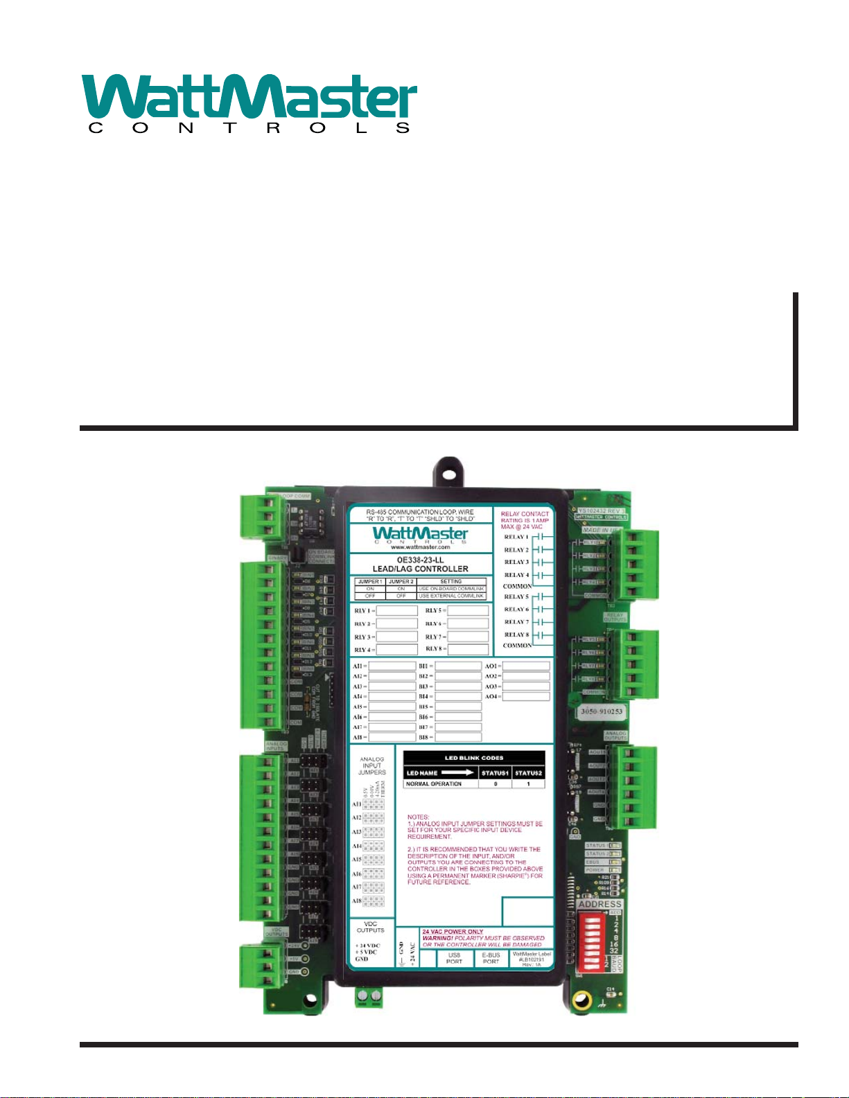
www.wattmaster.com
Lead/Lag Controller
Technical Guide
Page 2

Table of Contents
OVERVIEW ................................................................................................................................................. 3
Features ........................................................................................................................................................... 3
Step-By-Step Guide ......................................................................................................................................... 4
SECTION 1: LEAD/LAG WIRING & SETUP................................................................................................ 5
Environmental Requirements ........................................................................................................................... 5
Mounting .......................................................................................................................................................... 5
Power Supply ................................................................................................................................................... 5
Lead/Lag Controller Dimensions ...................................................................................................................... 5
Lead/Lag Wiring ............................................................................................................................................... 6
Communication Settings .................................................................................................................................. 7
Addressing and Baud Rate Selection .............................................................................................................. 8
SECTION 2: INSTALLING PRISM 2........................................................................................................... 9
SECTION 3: LEAD/LAG NAVIGATION AND STATUS ............................................................................... 10
SECTION 4: CONFIGURING ANALOG INPUTS ....................................................................................... 13
SECTION 5: CONFIGURING BINARY INPUTS ........................................................................................ 17
SECTION 6: CONFIGURING RELAYS...................................................................................................... 20
SECTION 7: CONFIGURING ANALOG OUTPUTS ................................................................................... 25
SECTION 8: OUTDOOR STATUS & LEAD/LAG ENABLE ......................................................................... 31
SECTION 9: SETTING SCHEDULES ....................................................................................................... 32
SECTION 10: CONFIGURING ALARMS .................................................................................................. 36
SECTION 11: SAVING AND RESTORING SETPOINTS ............................................................................ 37
SECTION 12: PRINTING STATUS REPORTS .......................................................................................... 39
APPENDIX A: SAMPLE CONFIGURATIONS ............................................................................................ 41
APPENDIX B: USB DRIVER INSTALLATION ........................................................................................... 48
INDEX ...................................................................................................................................................... 50
2
WattMaster Controls, Inc.
8500 NW River Park Drive · Parkville , MO 64152
Toll Free Phone: 866-918-1100
PH: (816) 505-1100 · FAX: (816) 505-1101 ·
E-mail: mail@wattmaster.com
Visit our web site at www.wattmaster.com
www.wattmaster.com
WattMaster Controls, Inc. assumes no responsibility for errors
or omissions.
This document is subject to change without notice.
Form: WM-LEADLAG-TGD-01A
Copyright December 2013 WattMaster Controls, Inc.
Lead/Lag Controller Technical Guide
Page 3

Overview
Lead/Lag Controller Overview
Overview
The OE338-23-LL Lead/Lag Controller is used for controlling
multiple pumps or HVAC units that require equal run time. The fi rst
application—Lead/Lag—is for controlling up to (4) sets of devices,
and the second application—2 Lead/1 Lag—is for controlling (3)
devices where (2) of the devices will be running at a time.
The Lead/Lag Controller has an on-board CommLink that provides
for stand-alone programming and monitoring via a direct USB
connection to a computer running Prism 2 software. If used on a
networked system that has an external CommLink, this on-board
CommLink would not be used.
The Lead/Lag Controller has (8) confi gurable analog inputs which
will accept signals from thermistor temperature sensors or from
4-20mA or 0-5VDC transmitters. The inputs are set for the desired
scaling by means of a jumper bar.
An additional modular input is available for WattMaster communicating sensors. The Lead/Lag Controller has (8) wet contact binary
inputs that can be confi gured for either normally open or normally
closed operation. Also available are (8) relay outputs for on/off
control and (4) analog outputs (0-10VDC) for modulating control.
There are (4) separate two events per day schedules which can be
assigned to any input or output for operational control or for alarm
recognition based on time of day.
NOTE: The Lead/Lag Controller contains no user-serviceable
parts. Contact qualifi ed technical personnel if your
Controller is not operating correctly.
Schedules can be confi gured to broadcast to other
WattMaster HVAC equipment installed on the same
communications loop as the Lead/Lag Controller
Can be confi gured using a computer with Prism 2
software installed
Can be operated Stand-Alone or connected to a
networked system
On-board CommLink for Stand-Alone programming
using a USB connection to a computer running Prism 2
software
Lead Lag Operation
The fi rst application option is the Lead/Lag operation. With the Lead/
Lag application, you can confi gure one “Lead” device and one or
more ”Lag” devices.
For example, if you have three pumps, but only one runs at a time
(Lead/Lag/Lag), the Lead/Lag Controller will run the fi rst pump for
a specifi ed period of time, then run the second for that amount of
time, and then fi nally run the third for that amount of time.
If any of the pumps fail, the Controller will switch to the next one
and generate an alarm. You can have multiple Lead/Lag functions
on the controller. For example, since the Controller has 8 relay
outputs, you could have up to 4 Lead/Lag combinations. Relays 1
and 2 could Lead/Lag the fi rst 2 pumps, relays 3 and 4 could Lead/
Lag the second set of pumps, etc. Or, you could have two sets of
Lead/Lag/Lag/Lag.
Features
The Lead/Lag Controller provides the following:
8 confi gurable analog inputs
8 wet contact binary inputs confi gured for normally open
or normally closed operation
8 relay outputs for on/off control
4 analog outputs (0-10VDC) for modulating control
E-BUS port for WattMaster communicating sensors
4 separate 2 events per day schedules which can be
assigned to any output for operational control or
alarm recognition based on time of day
Lead/Lag Controller Technical Guide
2 Lead / 1 Lag Operation
The second application option is the 2 Lead/1 Lag operation. The
2 Lead/1 Lag operation is used to control three devices to maintain
equal run times, where two of them are running at the same time.
The run time and failure operation would be the same as described
above. Only one “2 Lead/1 Lag” function can be confi gured on the
controller.
3
Page 4

Step-By-Step Guide
Step-By-Step Guide
Zone
Zone
Step-By-Step Guide
This guide will lead you through each step in confi guring your Lead/
Lag Controller. Below is a quick overview of each step.
Section 1: Lead/Lag Controller Wiring & Setup—This sec-
tion explains how to mount and wire your Lead/Lag Controller
properly. It also explains how to set the address and baud rate for
your particular system.
Section 2: Prism 2 Installation—This section explains how to
install Prism 2 software required to program your Lead/Lag Controller. If you are not familiar with the Prism 2 software program,
please refer to the Prism 2 Technical Guide which can be down-
loaded from the Orion Controls website: www.orioncontrols.com/
literature-new.html.
Section 3: Lead/Lag Controller Personalization & Status—
This section explains how to individualize and access Lead/Lag
Controllers when more than one is installed and also provides an
overview of the Lead/Lag Controller Status Screens.
Section 4: Confi guring Analog Inputs—This section explains
how to confi gure analog inputs, individualize analog input descrip-
tions, and calibrate thermistor sensors, and override and clear other
analog input values.
Section 5: Confi guring Binary Inputs—This section explains
how to confi gure binary inputs, individualize binary input descrip-
tions, and override binary inputs.
Section 7: Confi guring Analog Outputs—This section explains
how to confi gure analog outputs, individualize analog output descrip-
tions, override voltages, and cancel overrides.
Section 8: Outdoor Status and Lead Lag Enable—This section
explains the Override Status and Lead/Lag Enable Status.
Section 9: Setting Schedules—This section describes how
to confi gure daily and holiday schedules, perform schedule force
modes, and other scheduling functions.
Section 10: Confi guring Alarms—This section explains how to
confi gure and view alarms.
Section 11: Saving and Copying Setpoints—This section
explains how to save Lead/Lag setpoints to a fi le on your computer
and how to restore Lead/Lag setpoints once you have saved them
to a fi le. It also describes how to Load the Factory Default Settings.
Section 12: Printing Daily Status Reports—This section ex-
plains how to view and print Daily Status Reports.
Appendix A—This appendix provides Sample Confi gurations.
Appendix B—This appendix explains USB Driver Installation.
Index—The index provides page numbers for easy reference to
quickly fi nd the information you need.
Section 6: Confi guring Relays—This section explains how to
confi gure relay outputs and individualize relay descriptions.
4
Lead/Lag Controller Technical Guide
Page 5
Section 1: Lead/Lag Wiring & Setup
Dimensions and Mounting
Environmental Requirements
The Lead/Lag Controller needs to be installed in an environment that
can maintain a temperature range between -30°F and 150°F and not
exceed 90% RH levels (non-condensing).
Mounting
The Lead/Lag Controller is housed in a plastic enclosure. It is designed to be mounted by using the 3 mounting holes in the enclosure
base. It is important to mount the module in a location that is free
from extreme high or low temperatures, moisture, dust, and dirt. Be
careful not to damage the electronic components when mounting
the module.
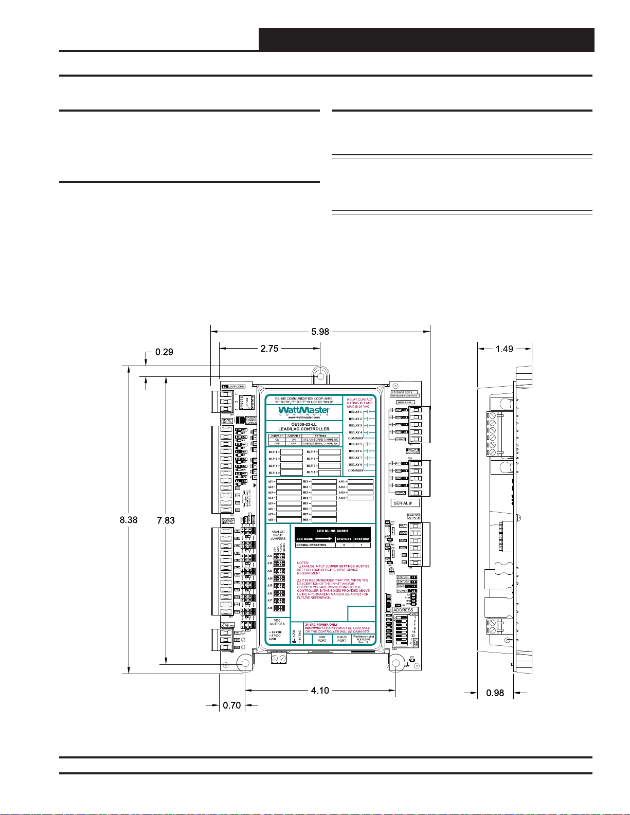
See Figure 1 for Controller dimensions (in inches).
Power Supply
The Lead/Lag Controller requires a 24 VAC power connection with
a minimum rating of 8 VA.
WARNING: Observe polarity! All boards must be wired
GND-to-GND and 24 VAC-to-VAC. Failure to
observe polarity could result in damage to the
boards.
Figure 1: Lead/Lag Controller Dimensions
Lead/Lag Controller Technical Guide
5
Page 6
Section 1: Lead/Lag Wiring & Setup
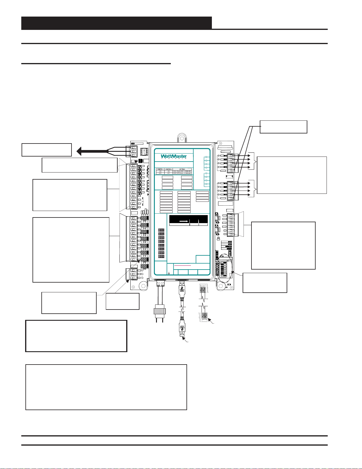
Installation & Wiring
Important Wiring Considerations
Please read carefully and apply the following information when
wiring the Lead/Lag Controller:
1. To operate the Lead/Lag Controller, you must connect power
to the 24 VAC input terminal block.
All Communication Loop Wiring Is
Straight Through
T To T, R To R, SHLD To SHLD
Local Loop RS-485
Connect To Next Device
On The Local Loop
CommLink Jumpers
Both On = Use On Board CommLink
Both Off - Use External CommLink
Binary Inputs BIN1Through BIN8
Configured for The Following:
1. Not Used
2. Normally Closed Operation
3. Normally Open Operation
4. Read Global Binary
Analog Inputs AI1Through AI8
Configured For the Following:
1. Thermistor 10K Ohm Type III
Temperature Sensors (Fahrenheit)
2. Thermistor 10K Ohm Type III
Temperature Sensors (Celsius)
3. 4 - 20mA User Scaled
4. 0 - 5 vdc User Scaled
5. Read Global Analog Broadcast from
another Controller
6. Communicating Temperature Sensor
7. Communicating Humidity Sensor
8. Communicating Carbon Dioxide
Jumpers - Typical
Jumpers Must Be Set
Correctly For The Type Of
Input You Require.
9600 Baud
BINARY
INPUTS
ANALOG
INPUTS
VDC
OUTPUTS
5 VDC & 24VDC
Power For
Sensors
LOOPCOMM
T-
SH
R+
TB1
COM
COM
COM
COM
TB3
GND
GND
GND
GND
TB7
+24V
+5V
GND
TB8
ON BOA
COMMLI
CONNEC
R38
BIN1
300
D6
R41
BIN2
300
D7
R43
300
BIN3
R47
D8
300
BIN4
D9
BIN5
300
D10
300
BIN6
D11
300
BIN7
R61R59R55R51
D12
300
BIN8
D13
CUTTO ISOLATE
COMFROM GND
4-20mA
THERM
0-10v
0-5v
AI1
AI1
AI2
AI3
AI2
AI4
AI5
AI3
AI6
AI7
AI4
AI8
AI5
AI6
AI7
AI8
OE338-23-LL
Lead Lag Controller
RS-485 COMMUNICATION LOOP. WIRE
“R” TO“R”, “T” TO “T” “SHLD” TO “SHLD”
www.wattmaster.com
OE338-23-LL
LEAD/LAG CONTROLLER
RLY1 =
RLY2 =
RLY3 =
RLY4 =
AI1 =
AI2 = BI2 = AO2 =
AI3 = BI3 = AO3 =
AI4 = BI4 = AO4 =
AI5 = BI5 =
AI6 = BI6 =
AI7 = BI7 =
AI8 = BI8 =
ANALOG
INPUT
JUMPERS
4-20mA
0-10V
0-5V
THERM
AI1
AI2
AI3
AI4
AI5
AI6
AI7
AI8
VDC
OUTPUTS
+ 24VDC
+ 5VDC
GND
24 VAC
GND
2. Check all wiring leads at the terminal block for tightness.
Be sure that wire strands do not stick out and touch adjacent
terminals. Confi rm that all sensors required for your system are
mounted in the appropriate location and wired into the correct
terminals. See Figure 2 for wiring.
24VAC Power
For Relay Outputs
YS102432 REV 3
®
#LB102191
Rev.: 1A
WATTMASTER CONTROLS
RLY1
RLY2
RLY3
RLY4
COMMON
RLY1
RLY2
RLY3
RLY4
COMMON
SERIAL #
1002
R74
U17
AOUT1-2
.1uF
C36
R97
1002
U19
AOUT3-4
.1uF
C46
GND
.1uF
ADDRESS
1002
1002
1002
1002
1002
1002
1002
1002
SW1
MADE IN USA
AOUT1
AOUT2
AOUT3
AOUT4
GND
GND
STATUS1
STATUS2
EBUS
POWER
C21
R109
TB2
RELAY
OUTPUTS
TB4
ANALOG
OUTPUTS
TB6
R21
R16
R14
8 Relay Outputs Are Available For
On/Off Control Of Equipment
Configured For the Following:
1. Lead Relay for Lead/Lag Control
2. Lag Relay for Lead/Lag Control
Analog Outputs AOUT1 through
AOUT4 Provide (4) 0-10 VDC
Outputs Configured For The
Following:
1. Not Configured
1002
1002
1002
1002
ADD
1
2
4
8
16
32
LOOP
BAUD
1
2
C14
.01uF
2. Direct Acting Floating Point
3. Reverse Acting Floating Point
4. Direct Acting PID
5. Reverse Acting PID
ADDRESS Dipswitch
is Used for Setting
the Address and
Baud Rate.
RELAYCONTACT
RATING IS 1AMP
MAX @ 24 VAC
RELAY1
RELAY2
RELAY3
RELAY4
COMMON
RELAY5
LED BLINK CODES
USB
E-BUS
PORT
PORT
RELAY6
RELAY7
RELAY8
COMMON
WattMaster Label
RLY5 =
RLY6 =
RLY7 =
RLY8 =
BI1 = AO1 =
LED NAME STATUS1 STATUS2
NORMAL OPERATION 0 1
NOTES:
1.)ANALOG INPUT JUMPER SETTINGS MUST BE
SET FORYOUR SPECIFIC INPUT DEVICE
REQUIREMENT.
2.) IT IS RECOMMENDEDTHAT YOU WRITE THE
DESCRIPTION OF THE INPUT,AND/OR
OUTPUTS YOUARE CONNECTING TO THE
CONTROLLER IN THE BOXES PROVIDEDABOVE
USINGA PERMANENT MARKER (SHARPIE) FOR
FUTURE REFERENCE.
24 VAC POWER ONLY
WARNING!POLARITY MUST BE OBSERVED
OR THE CONTROLLER WILL BE DAMAGED
GND
+24VAC
Line Voltage
Warning:
24 VAC Must Be Connected So That All
Ground Wires Remain Common. Failure To
Do So Will Result In Damage To The
Controller
NOTES:
1.)24 VAC Must Be Connected So
That All Ground Wires Remain
Common.
2.)All Wiring To Be In Accordance With
Local And National Electrical Codes
and Specifications.
3.)All Communication Wiring To Be 18
Ga. Minimum, 2 Conductor Twisted
Pair With Shield. Belden #82760 Or
Equivalent.
4.)It Is Recommended That The
Address Switch Is Set Before
Installation.
Figure 2: Lead/Lag Controller Wiring Diagram
6
24 VAC
Transformer
8 VA
Minimum
EBC E-BUS Cable
Connect to
Communicating Sensor
USB Cable
Connect to Computer with
Prism 2 Software Installed For
Stand-Alone Programming
Lead/Lag Controller Technical Guide
Page 7
Section 1: Lead/Lag Wiring & Setup
Communication Settings
Before Applying Power
In order to have a trouble free start-up, it is important to follow a
few simple procedures. Before applying power for the fi rst time, it
is very important to correctly address the controller and run through
a few simple checks.
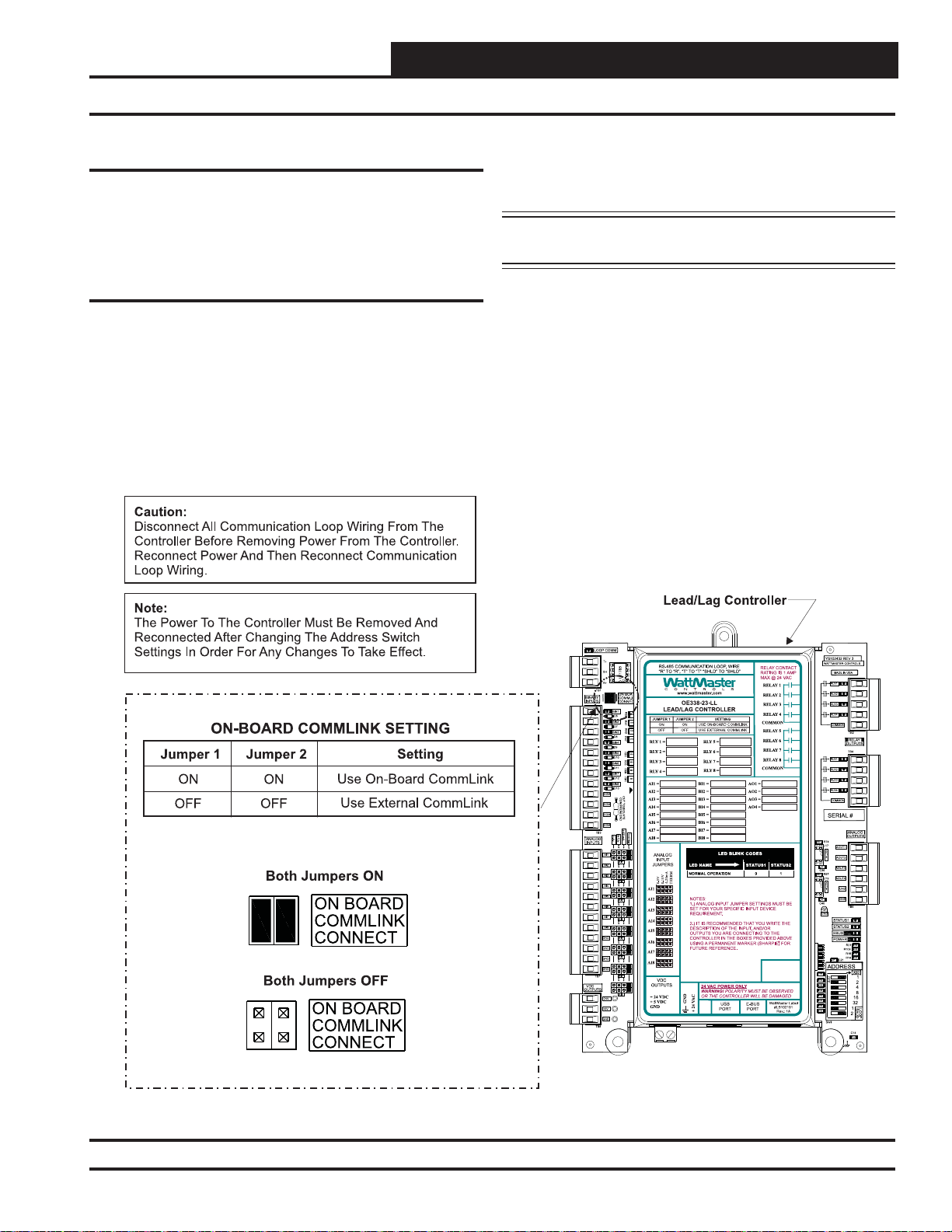
Communication Settings
Stand Alone Operation
The Lead/Lag Controller has an on-board CommLink that is used
during Stand-Alone Operation. When confi gured for Stand-Alone
operation, a computer running Prism 2 software can be connected
directly to the USB port located at the bottom of the Lead/Lag
Controller for programming and monitoring. In order to operate in
Stand-Alone Mode, two things need to be set. First, both CommLink
Jumpers found on the upper left hand side of the board need to be set
to ON. See Figure 3 for details. Second, the Baud Rate determined
by setting ADDRESS Dipswitches 7 and 8 needs to be set to OFF/
ON. See Figure 4, page 8 for details.
NOTE: If using the Internal CommLink, you must set up
the USB drivers. See Appendix B, page 48.
Network Operation
The Lead/Lag Controller can be confi gured for connection to a
networked system that has an external CommLink. In this case, the
on-board CommLink would not be used. For this confi guration,
two things need to be set. First, both CommLink Jumpers found on
the upper left found on the upper left hand side of the board need
to be set to OFF. See Figure 3 for details. Second, the Baud Rate
determined by setting ADDRESS Dipswitches 7 and 8 needs to be
set to OFF/OFF if using a CommLink IV and to OFF/ON if using a
CommLink 5. See Figure 4, page 8 for details.
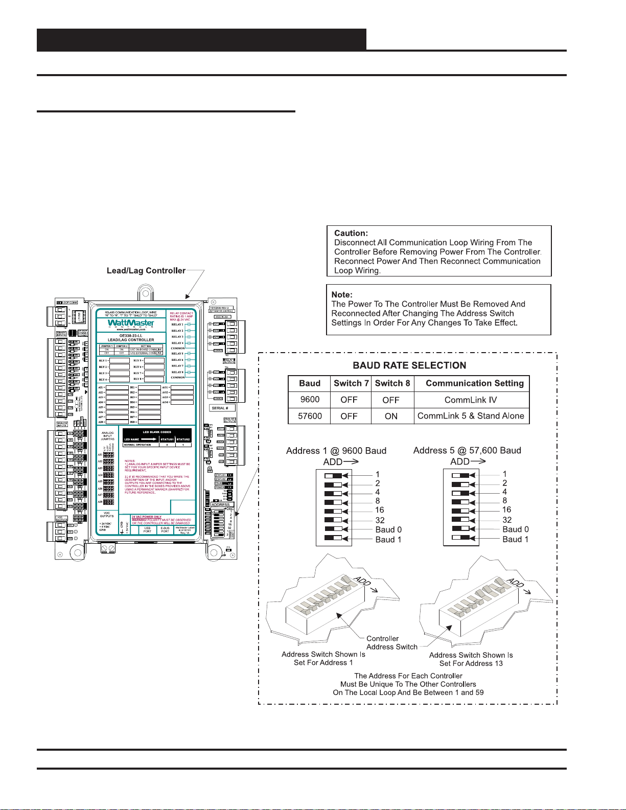
Figure 3: Lead/Lag Controller Address Switch Setting
Lead/Lag Controller Technical Guide
7
Page 8
Section 1: Lead/Lag Wiring & Setup
Addressing and Baud Rate Settings
Zone
Zone
Controller Addressing and Baud Rate
The Lead/Lag Controller is equipped with address switches. When
using Prism 2 to program and confi gure the Lead/Lag Controller,
you would enter this address to communicate with the controller.
When the system is to be connected to other HVAC unit controllers
on a communication loop, each controller’s address switch must be
set with a unique address between 1 and 59.
Address switches 7 and 8 are used for the baud rate selection. See
Figure 4 below for baud rate setting information.
Figure 4: Lead/Lag Controller Address Switch Setting
8
Lead/Lag Controller Technical Guide
Page 9
Section 2: Installing Prism 2
Initialization and Prism 2 Software
Initialization
On system power up, there is an approximately 30-second startup
delay where all default setpoints are initialized, LED’s are initialized,
and all outputs are turned off.
When power is fi rst applied, the STATUS1 LED will fl ash intermit-
tently for about 10 seconds. After a short pause, STATUS1 LED
and STATUS2 LED will fl ash out the controller address. STATUS1
LED will fl ash to represent the tens position. STATUS2 LED will
fl ash to represent the ones position. After the controller address is
complete, there will be a short pause while the initialization process
is completed. There will be no controller operation or communications during initialization. After initialization, STATUS2 LED will
continuously fl ash the status code—(1) blink indicates Normal
Operation; (2) blinks indicates a Push-Button Schedule Override
is in effect.
Example of a controller address of 25:
STATUS1 LED will fl ash 2 times. STATUS2 LED will fl ash 5 times.
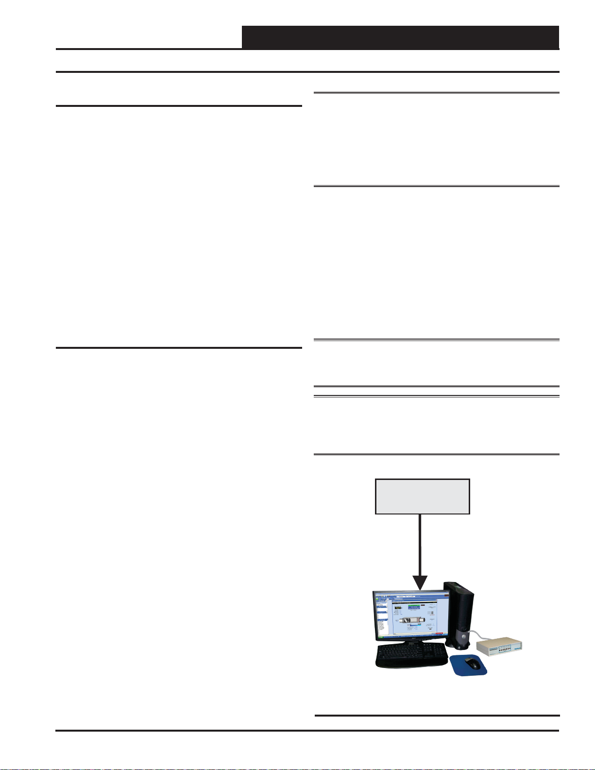
Prism 2 Software
The next step is programming the controller for your specifi c require-
ments. In order to confi gure and program the Lead/Lag Controller,
you must use Prism 2 software. This gives you access to the status,
confi guration, and setpoint screens of the Lead/Lag Controller. The
software is distributed on CD or can be downloaded for free from
our website: www.wattmaster.com/techsupport.
If you are unfamiliar with Prism 2, we recommend that you reference
the Prism 2 Technical Guide to familiarize yourself with the program.
* NOTE: The Lead/Lag Controller has a built-in CommLink
that can be utilized in Stand-Alone Mode. See page 7 for
sett i ng up St and -A lone a nd Net work operations. In Net-
work Mode, you must have a CommLink IV or CommLink
5 installed in order to communicate between your computer and
the system. If remote communication is required, a WattMaster IPModule (Ethernet) must also be installed in the CommLink.
Software License
Prism 2 does not require any license agreement and may be freely
copied and distributed.
Support Information
WattMaster Controls provides Prism 2 installation and confi guration
support. Call (866) 918-1100 for free, direct telephone support or
(816) 505-1100 to talk to a Technical Support Representative. Support for all telephone services is available Monday through Friday,
7:00 AM to 5:00 PM central standard time.
NOTE: WattMaster Controls Technical Support can-
not troubleshoot internal PC and/or Windows®-based
operating system problems.
NOTE: WattMaster Controls Technical Support can-
not troubleshoot fi rewalls, r oute rs, a nd/o r p robl ems
on a customer’s internal or external network. An IT
professional may need to be consulted.
System Requirements
To use Prism 2 you must have a computer that meets or exceeds the
following requirements:
Operating System
• Microsoft
Windows
NOTE: Prism 2 is not intended for a server/client
environment.
Minimum Hardware
• Windows
®
Windows® 2000/ Windows® Vista,
®
7 or Windows® 8
®
compatible computer
• Pentium 2 GHz Processor (Pentium 4 2 GHz or
greater, Recommended)
• 1 GB RAM (or greater)
• 120 MB hard drive space
• XVGA (1024 x 768) adapter and monitor
(1280 x 1024, Recommended)
• Network card for TCP/IP connection when IP
Module is used.
• CommLink*
Lead/Lag Controller Technical Guide
Operator
Interface
Figure 5: Computer with Prism 2 Software Installed
and CommLink
9
Page 10
Section 3: Lead/Lag & 2 Lead/1 Lag Navigation & Status
Unit Selection
Selecting and Naming Lead/Lag Controllers
Selecting Lead/Lag Controllers
NOTE: See the Prism 2 Technical Guide for instructions on
setting up the job site and doing a search for units.
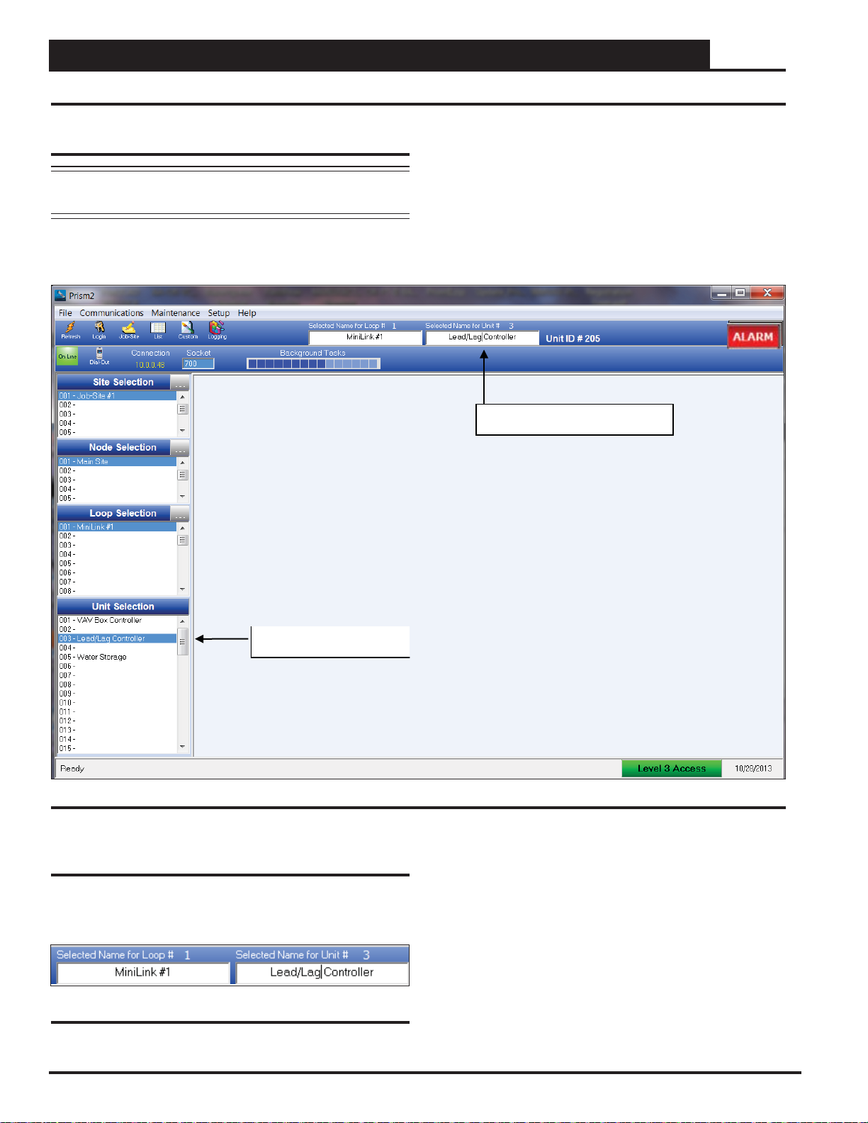
From the Prism 2 Main Screen, click on the Lead/Lag Controller
address in the Unit Selection W indow. In this example, it is address
3. See Figure 6.
Selected Name Dialog Box
Figure 6: Prism 2 Main Screen Lead/Lag Controller Selection
Naming Lead/Lag Controllers
If you have more than one Lead/Lag Controller, you can rename it in
the Selected Name Dialog Box. See Figur e 7. Many users name their
Lead/Lag Controller according to the application that it performs.
Figure 7: Naming the Lead/Lag Controller
10
Lead/Lag Controller Technical Guide
Page 11
Section 3: Lead/Lag & 2 Lead/1 Lag Navigation & Status
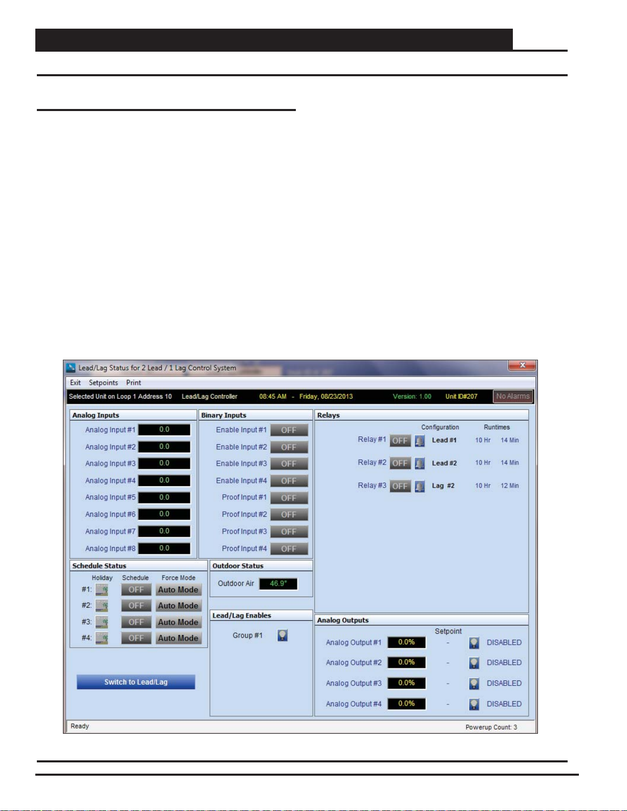
Lead/Lag Status Screen
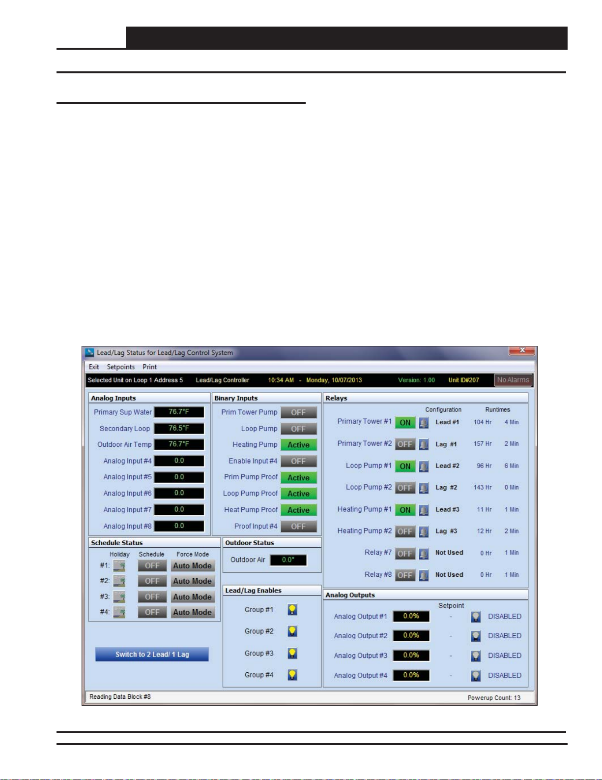
Lead/Lag Status Screen
Figure 8 depicts the Lead/Lag Status Screen. To access the Lead/
Lag Status Screen, you might need to click the <Switch to Lead/
Lag> button found on the lower left of the 2 Lead/1 Lag Status
Screen (Figure 9, page 12).
The screen is divided into separate windows as follows: Analog In-
puts, Binary Inputs, Relays, Analog Outputs, Outdoor Status, Lead/
Lag Enables, Schedule Status, and Alarms.
The Lead/Lag Status Screen Toolbar also gives you the options to
access Reset Factory Defaults, Save and Restore Setpoints, and Print
a Status Report for the current day.
The Lead/Lag Status Screen provides real-time live updates of the
current operating conditions and is used to access the various setpoint
and confi guration options.
No control takes place until you confi gure the operation of the Lead/
Lag application.
Once you confi gure your inputs, outputs, and operating schedules,
everything you need to monitor the Lead/Lag application is found
on this Lead/Lag Status Screen.
The rest of this technical guide explains each component on this
screen and provides detailed instructions for confi guring the data.
The following is a list of topics and their page numbers:
Analog Inputs, page 13
Binary Inputs, page 17
Relays, page 20
Analog Outputs, page 25
Outdoor Status, page 31
Lead/Lag Enables, page 31
Schedules, page 32
Confi guring Alarms, page 36
From the Top Toolbar:
Setpoints, Restore Defaults, page 37
Setpoints, Save and Restore, pages 37 & 38
Print Status Report, page 39
Figure 8: Lead/Lag Status Screen
Lead/Lag Controller Technical Guide
11
Page 12
Section 3: Lead/Lag & 2 Lead/1 Lag Navigation & Status
2 Lead / 1 Lag Status Screen
2 Lead / 1 Lag Status Screen
Figure 9 depicts the 2 Lead/1 Lag Status Screen. To access the 2
Lead/1 Lag Status Screen, you might need to click the
Lead/1 Lag>
Screen (Figure 8, page 11).
The screen is divided into separate windows as follows: Analog In-
puts, Binary Inputs, Relays, Analog Outputs, Outdoor Status, Lead/
Lag Enables, Schedule Status, and Alarms.
The 2 Lead/1 Lag Status Screen Toolbar also gives you the options
to access Reset Factory Defaults, Save and Restore Setpoints, and
Print a Status Report for the current day.
The 2 Lead/1 Lag Status Screen provides real-time live updates of
the current operating conditions and is used to access the various
setpoint and confi guration options.
No control takes place until you confi gure the operation of the 2
Lead/1 Lag application.
button found on the lower left of the Lead/Lag Status
<Switch to 2
Once you confi gure your inputs, outputs, and operating schedules,
everything you need to monitor the 2 Lead/1 Lag application is found
on this 2 Lead/1 Lag Status Screen.
The rest of this technical guide explains each component on this
screen and provides detailed instructions for confi guring the data.
The following is a list of topics and their page numbers:
Analog Inputs, page 13
Binary Inputs, page 17
Relays, page 20
Analog Outputs, page 25
Outdoor Status, page 31
Lead/Lag Enables, page 31
Schedules, page 32
Confi guring Alarms, page 36
From the Top Toolbar:
Setpoints, Restore Defaults, page 37
Setpoints, Save and Restore, pages 37 & 38
Print Status Report, page 39
Figure 9: 2 Lead/1 Lag Status Screen
12
Lead/Lag Controller Technical Guide
Page 13
Section 4: Confi guring Analog Inputs
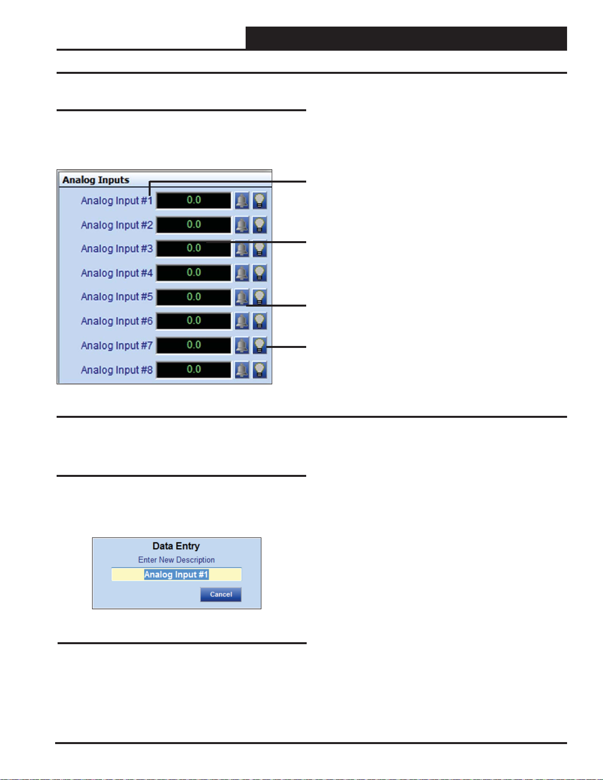
Analog Inputs
The Analog Inputs W indow is located in the upper left-hand side of
the Lead/Lag Status Scr eens (Figures 8 & 9, pages 11 & 12). There
are 8 Analog Inputs. See Figure 10 for the Analog Inputs Window
component summary and the pages that follow for details.
Analog Inputs
Right or Left-click on any of the Analog Input name
fi elds to access the description entry box to add or
change the name of the Analog Input.
Left-Click in the data entry fi eld to confi gure the Analog
Input.
Right-Click on these fi elds to access the Calibration,
Override, and Clear Override.
The bell will light up to indicate that an alarm is on.
The Light bulb will light up when the Input is in the
Occupied Mode.
Figure 10: Analog Input Window Components and Navigation
Renaming Analog Inputs
To give an Analog Input a new name, click on the blue highlighted
Analog Input # fi eld and the Analog Input Data Entry Dialog Box
will open (Figure 11). Once you have typed in a new description,
<ENTER> to save. The maximum number of characters is 17.
press
Figure 11: Analog Input Data Entry Dialog Box
Lead/Lag Controller Technical Guide
13
Page 14
Section 4: Confi guring Analog Inputs
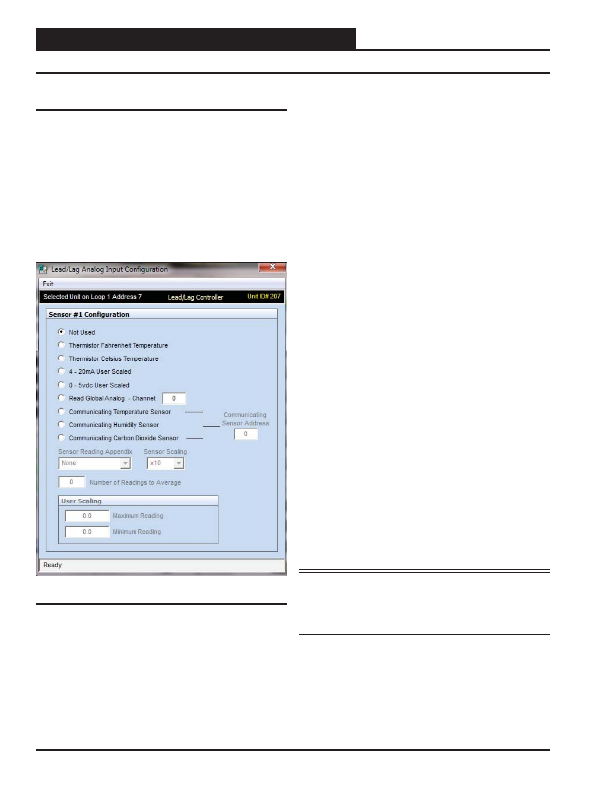
Analog Input Confi guration Screen
Confi guring Analog Inputs
Left-click in the data entry fi eld in the Analog Inputs Window to open
the Analog Input Confi guration Window (Figure 12).
The eight analog inputs can be confi gured in several different ways.
Generally, the fi rst four inputs are the only ones used for Lead/Lag
control. These inputs can be used to generate an alarm and switch
from one device to another if the fi rst cannot maintain a temperature
or PSI setpoint. The others can be used to monitor various inputs.
The controlling devices can be set up to look at one sensor or each
device can have its own sensor.
The following confi gurations are available for each Analog Input:
Not Used
●
Thermistor Fahrenheit Temperature: 10K Ohm Type III
●
Scaled for Fahrenheit. Set jumper to the appropriate setting
(see Figure 2, page 6).
Thermistor Celsius Temperature: 10K Ohm Type III
●
Scaled for Celsius. Set jumper to the appropriate setting (see
Figure 2, page 6).
4 - 20mA User Scaled: 4-20mA User-Scaled Sensor. Set
●
jumper to the appropriate setting (see Figure 2, page 6).
0 - 5vdc User Scaled: Select this option if using a 0-5vdc
●
scaled sensor. Set jumper associated with this input to the
appropriate 0-5v setting (see Figure 2, page 6.)
●
Read Global Analog Broadcast Channel from Another
Controller
● Communicating Temperature Sensor ( OE217-02):
If using a WattMaster Communicating Temperature
Sensor with a modular cable, confi gure this input to read
the appropriate Communicating Sensor Address. Enter
an address from 1-8 in the < Communicating Sensor
Address>
fi eld and press <ENTER>.
Figure 12: Analog Input Confi guration Window
Communicating Humidity Sensor ( OE217-03): If using
●
a combination Temperature and Humidity Communicating
Sensor with a modular cable, confi gure one input to read
the temperature and another input to read the humidity,
both using the same Communicating Sensor address. Enter
an address from 1-8 in the <Communicating Sensor
Address>
●
Communicating Carbon Dioxide Sensor ( OE256-05
or OE256-07)
Sensor with a modular cable, confi gure this input to read
the appropriate Communicating Sensor Address. Enter
an address from 1-8 in the <Communicating Sensor
Address>
*NOTE: See the E-BUS Digital Room Sensor Technical Guide,
fi eld and press <ENTER>.*
: If using a WattMaster Communicating CO2
fi eld and press <ENTER>.*
E-BUS Wall-Mounted CO
or E-BUS Duct-Mounted CO
for information on how to address the communicating sensors.
Sensor Technical Guide,
2
Sensor T echnical Guide
2
14
Lead/Lag Controller Technical Guide
Page 15
Section 4: Confi guring Analog Inputs
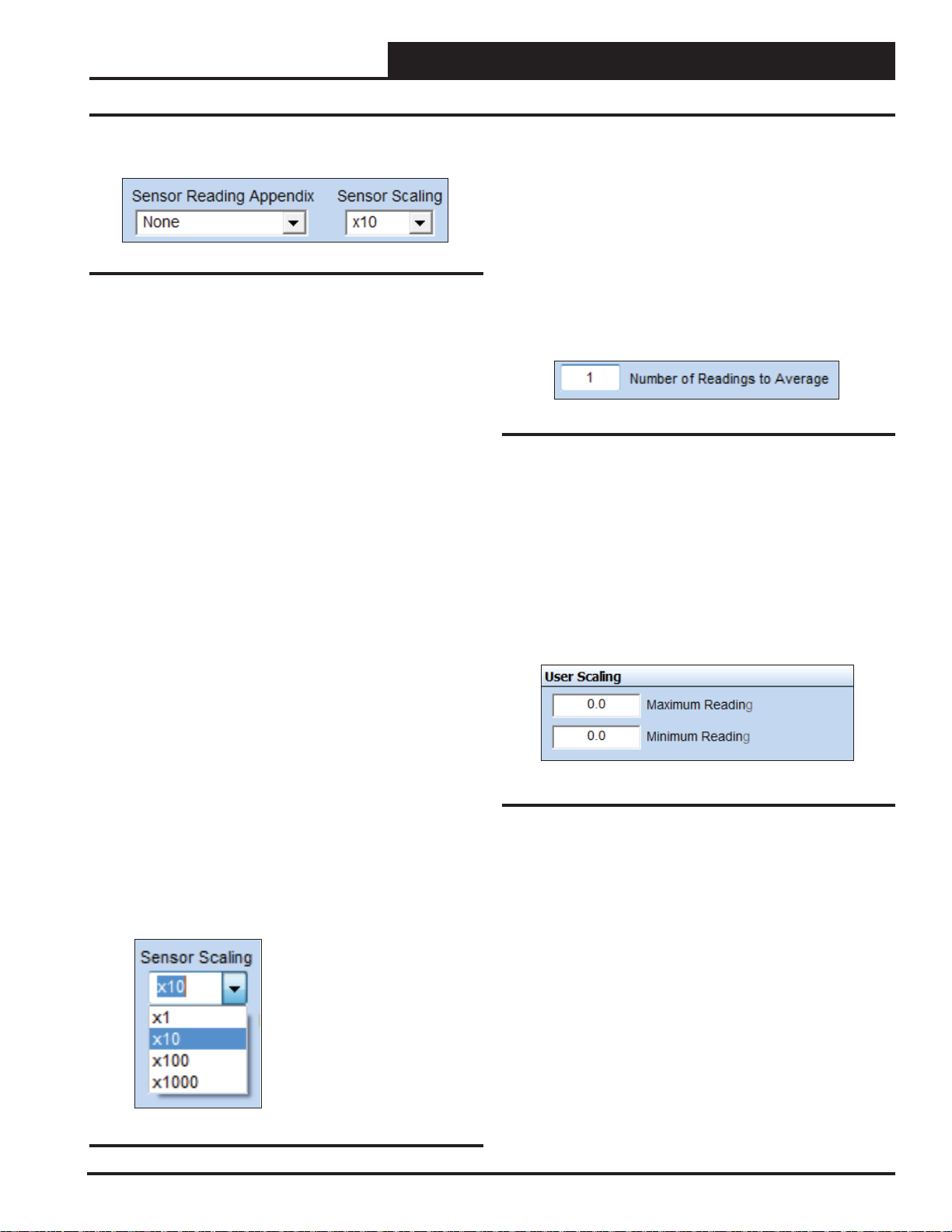
Sensor Reading, Scaling, and Override Duration
Sensor Reading Appendix
Figure 13: Sensor Reading Appendix Field
Select from the drop down list in the <Sensor Reading Appendix>
fi eld (Figure 13) to give the sensor reading a qualifi er.
●
None: No Appendix Required
● RH%: Humidity Percentage
%: Percentage
●
°F: Fahrenheit
●
°C: Celsius
●
PPM: Parts per Million
●
PSI: Pound per Square Inch
●
“WG: Inches of Water Gauge
●
“: Inches
●
Ft.: Feet
●
RPM: Revolutions per Minute
●
VDC: Volts D.C.
●
Number of Readings to Average
This function has the capability of averaging up to 25 sensor readings
before it displays a new value on one of the Lead/Lag Controller
Status Screens. Sensor values are read once per second.
Type the number of readings from this sensor you want to aver-
age in the <Number of Readings to Average> fi eld and press
<ENTER> to save. See Figure 15. Valid entries are from 1-25.
If you want the input sensor to only show its most current reading,
enter <1>.
Figure 15: Number of Readings to Average Field
User Scaling
The User Scaling Box allows you to set a Maximum and Minimum
Reading for the specifi c 4-20 mA or 0-5 vdc sensor you are using.
This means you can display values with ± 1, ± 0.1, ± 0.1± 0.01 or
higher resolutions. Just keep in mind that the maximum value that
can be sent from the controller is ±30,000, so if you have scaled your
reading to ± 0.001, then the maximum value you can send is ± 30
with the 3 additional decimal values (30.000). See Figure 16. Type
in the values and press <ENTER> to save.
BTU: British Thermal Unit
●
CFM: Cubic Feet per Minute
●
Hr: Hours
●
Min: Minutes
●
GPM: Gallons per Minute
●
kPa: Kilopascals
●
Sensor Scaling
All readings are user-scalable according to the number of digits
to the right of the decimal point. See Figure 14 and values and
examples below.
●
X 1 65°F
● X 10 65.5°F
● X 100 65.54°F
● X 1000 65.543°F
Figure 16: User Scaling Box
Figure 14: Sensor Scaling Field
Lead/Lag Controller Technical Guide
15
Page 16
Section 4: Confi guring Analog Inputs
Calibrate, Override, and Clear Sensor Override
Calibrate, Override, and Clear Sensor
Override
Once confi gured, all readings can be overridden to specifi c values
for test purposes. Additionally, all thermistor sensors can also be
calibrated by entering positive or negative offsets to be applied to
the current readings.
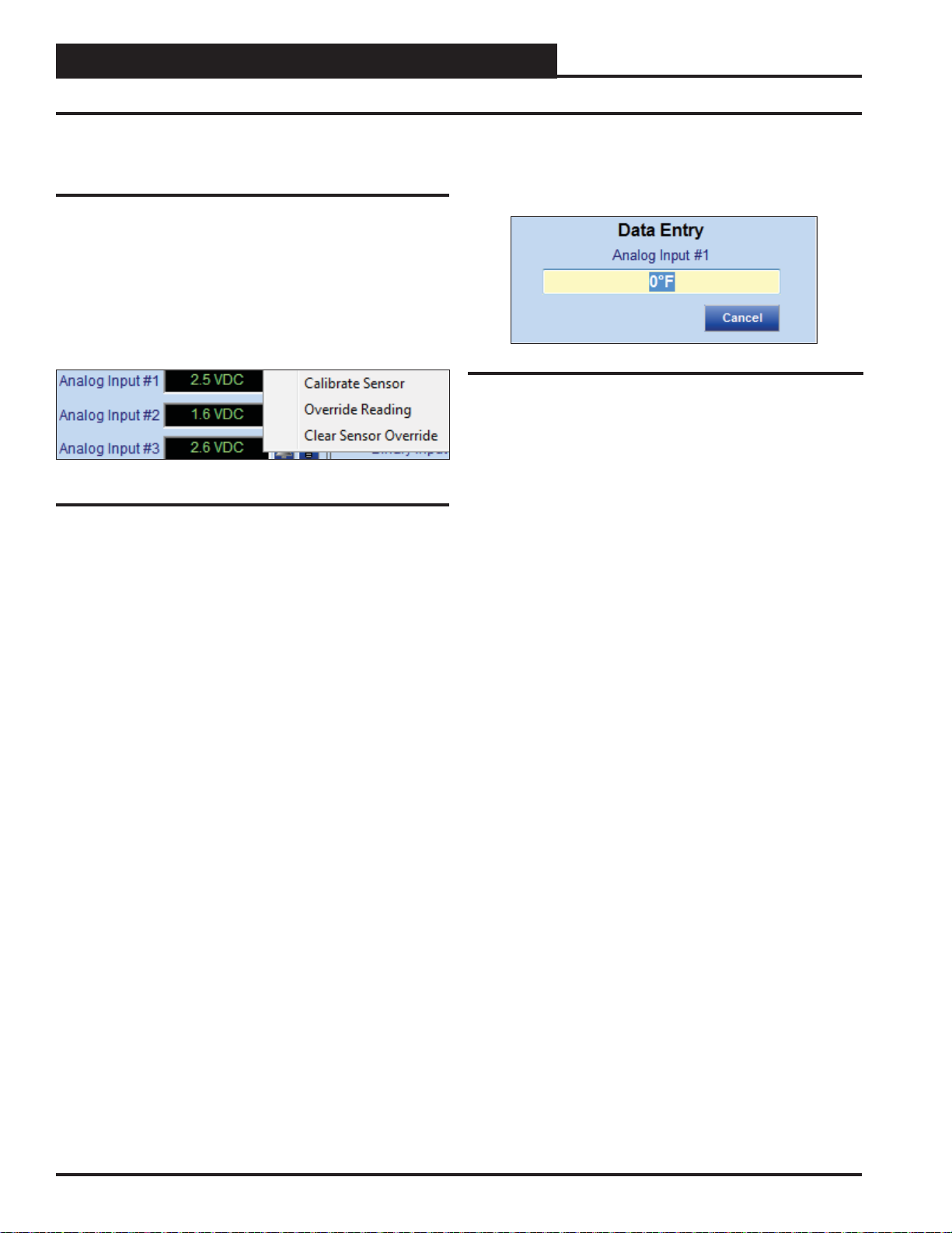
Right-click in the data entry fi eld in the Analog Inputs Window to
open the Calibrate, Override, and Clear Sensor Override Pop-Up
Menu shown in Figure 17 and select the desired function.
Figure 17: Calibrate and Override Sensor
If you select Calibrate Sensor or Override Reading, the data entry
window as shown by Figure 18 will open. Left-click in the yellow
text fi eld, type in the desired value, and press <ENTER> to save.
Figure 18: Data Entry Field
Calibrate Sensor: Type a positive or negative offset that
●
will be applied to the current reading and press
to save. NOTE: The reading Offset can be from -100° to +
100°. This function only applies to Thermistor Temperature
Sensors.
Override Reading: Type a value that will override the
●
actual sensor reading and press <ENTER> to save.
Clear Sensor Override: Select to clear a sensor override
●
that was entered.
<ENTER>
16
Lead/Lag Controller Technical Guide
Page 17
Section 5: Confi guring Binary Inputs
Binary Inputs
The Binary Inputs W indow is located in the upper center of the Lead/
Lag Controller Status Scr eens (Figures 8 & 9, pages 1 1 & 12). There
are 8 Binary Inputs. Binary Inputs are used as either Enable Inputs
or Proof Inputs. These Binary Inputs are 24 VAC wet contacts. See
Figure 19 for the Binary Inputs Window component details.
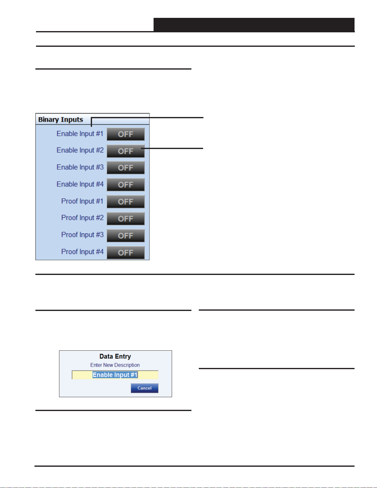
Components and Navigation
Right or Left-click on any of the Binary Input name
fi elds to access the description entry box to add or
change the name of the Binary Input.
Left-click on the Status box to confi gure the Binary
Input.
Right-click to override the Binary Input.
Figure 19: Binary Input Window Components and Navigation
Renaming Binary Inputs
To give the Binary Input a new name, click on the blue highlighted
Binary Input # fi eld and the Binary Input Data Entry Dialog Box
will open (Figure 20). Once you have typed in a new description
(max 17 characters), press <ENTER> to save.
Enable Inputs
The fi rst 4 Binary Inputs are Enable Inputs—Inputs #1-#4. Enable
Inputs can be used to activate the Lead/Lag devices. Confi guring
the Lead/Lag devices to use the Enable (Activation) Inputs is done
in the Relay Confi guration Screens.
Proof Inputs
The last 4 Binary Inputs are Proof Inputs—Inputs #5-#8. Proof Inputs
are used to prove that the devices are operating correctly. They can
be such things as air fl ow switches, water fl ow switches, or pressure
differential switches. Confi guring the Lead/Lag devices to use the
Figure 20: Binary Input Data Entry Dialog Box
Proof Inputs is done in the Relay Confi guration Screens.
Lead/Lag Controller Technical Guide
17
Page 18

Section 5: Confi guring Binary Inputs
Binary Input Type and Override
Confi guring Binary Inputs
Left-click on the “ON” or “OFF” button to the right of Binary Input
#1 in the Binary Input Window (Figure 19, page 17) to open the
Binary Input Confi guration Window (Figure 21). Each Binary Input
is separately confi gured, so 8 binary input combinations are possible
for one controller.
Figure 21: Binary Input Confi guration Window
Binary Confi guration
The following confi gurations are available for each Binary Input:
Override
Once configured, Binary Inputs can be overridden to specific
conditions.
Right-click on the Status box in the Binary Inputs Window (Figure
19, page 17) to open the Override Binary Input Dialog Box shown
in Figure 22, and select the desired function.
Figure 22: Override Binary Input
●
AUTO: Select to have a Binary Input turn ON and OFF on
its own.
ON: Select to override and turn a Binary Input ON.
●
OFF: Select to override and turn a Binary Input OFF.
●
Not Used
●
N/O Contact (Closes for Active) - This normally open
●
(N/O) input will become active when 24 VAC is applied.
N/C Contact (Opens for Active) - This normally closed
●
(N/C) input will become active when 24 VAC is removed.
Read Global Binary - This input will read the Global
●
Binary on the selected channel.
18
Lead/Lag Controller Technical Guide
Page 19

Section 6: Confi guring Relays
Lead/Lag Relays
The Relays Window is located in the upper right of the Lead/Lag
Controller Status Screens (Figures 8 & 9, pages 11 & 12). There
are 8 Relays. See Figure 23 for the Lead/Lag Relays W indow component summary and the pages that follow for details. See Figure
24 for the 2 Lead/1 Lag Relays Window component summary and
the pages that follow for details.
Components and Navigation
Right or left-click on any of the Relay fi elds
to access the description entry box to add or
change the name of the Relay.
Left-click on this Status box to confi gure the
Relays.
Right-click to override the Relay.
The bell will light up to indicate that an alarm
is on.
Figure 23: Lead/Lag Relays Window
Amount of time in hours and minutes that the
relay has been energized.
Renaming Relays
To give the Relay a new name, click on the blue highlighted Relay
# fi eld and the Relay Data Entry Dialog Box will open (Figur e 25).
Once you have typed in a new description, press <ENTER> to save.
Figure 24: 2 Lead/1 Lag Relays Window
Lead/Lag Controller Technical Guide
Figure 25: Relay Data Entry Dialog Box
19
Page 20

Section 6: Confi guring Relays
Lead/Lag Relay Confi guration Window
Confi guring Lead/Lag Relays
Left-click on the “ON” or “OFF” button to the right of the Relay #
in the Relays Window (Figure 23, page 19) to open the Lead/Lag
Relay Confi guration Screen. (Figure 26).
One relay can be confi gured as the lead and up to 7 relays can be lag.
There are (8) relays that can be confi gured.
The Relay Confi guration Screen contains (4) windows which are
described on the pages that follow:
● Main Control Method
● Timers
● Relay Output Type
● Lead/Lag Proof Setpoint Help
Figure 26: Lead/Lag Relay Confi guration Screen
20
Lead/Lag Controller Technical Guide
Page 21

Section 6: Confi guring Relays
Lead/Lag Relay Confi guration Window
Confi guring 2 Lead/1 Lag Relays
Left-click on the “ON” or “OFF” button to the right of the Relay #
in the Relays Window (Figure 24, page 19) to open the 2 Lead/1
Lag Relay Confi guration Screen. (Figure 27).
Only three relays are used. Two of them are confi gured as Lead
and 1 is Lag.
The 2 Lead/1 Lag Relay Confi guration Screen contains (4) windows
which are described on the pages that follow:
● Main Control Method & Control Source
● Timers
● Relay Output Type
● Lead/Lag Proof Setpoint Help
Figure 27: 2 Lead/1 Lag Relay Confi guration Screen
Lead/Lag Controller Technical Guide
21
Page 22

Section 6: Confi guring Relays
Control Method and Control Source
Control Method
The Control Method Drop Down Menu (Figure 28) is located on
the top left of the Relay Confi guration Screens (Figure 26 & 27,
page 20 & 21). As you select items, the corresponding fi elds that
you need to fi ll out will become available. Fields that do not pertain
to the confi guration at hand will be greyed out.
Figure 28: Control Method Drop Down Menu
For Lead/Lag confi guration, one relay will be the Lead and up to
seven can be the Lag, and they are confi gured from their own Relay
Confi guration Screens. For 2 Lead / 1 Lag, two relays are Lead and
one is Lag and all three relays are confi gured from Relay #1 screen.
The choices are one of the following methods of control listed below:
●
Not Confi gured
● Lead Relay
● Lag Relay
Lead Relay – If this option is selected, you can also select a Control
Source input in the next fi eld to be used as a Proof of Operation to
allow switching to the Lag Relay upon a failure. This proof can
either be a binary contact activation or an analog input level. If
your Proof is an analog input level, you can then confi gure either
an Increasing or Decreasing Proof Setpoint (Figure 30, page 23).
Control Source
Figure 29: Control Source Field
The Control Source Options in the Control Sour ce Drop Down Menu
(Figure 29) are shown below:
●
Not Confi gured
● Analog Input #1
● Analog Input #2
● Analog Input #3
● Analog Input #4
● Analog Input #5
● Analog Input #6
● Analog Input #7
● Analog Input #8
● Proof Input #1
● Proof Input #2
● Proof Input #3
● Proof Input #4
● Outdoor Air
If your Proof is a Binary Input, the Proof Failure is initiated when
the selected Binary Input is “Active” (See Binary Input Activation
Window, Figure 35, page 24.)
In the Timers Window (Figure 36, page 24) found at bottom left of
the Lead/Lag Relay Confi guration Screen ( Figur e 26, page 20), you
can confi gure a Lead/Lag Changeover Interval and a Proof Failure
Timeout Delay.
Lag Relay – This Lag Relay will follow the same confi gurations
as the Lead Relay.
22
Lead/Lag Controller Technical Guide
Page 23

Section 6: Confi guring Relays
Increasing and Decreasing Proof Setpoints
Increasing Proof Setpoint
Figure 30: Increasing Proof Setpoint
Use this option if you want to use a temperature as proof that the
device is operating correctly and to determine if the unit has failed
if it cannot maintain a temperature that is above this setpoint. For
example, if the unit is trying to maintain a 80° supply air temperature
and drops below this setpoint for the “ Proof Failure Timeout Delay”,
then the Lead/Lag controller will shut off the device that is running,
start the backup device, and generate an alarm.
Decreasing Proof Setpoint
Figure 31: Decreasing Proof Setpoint
Use this option if you want to use a temperature as proof that the
device is operating correctly and to determine if the unit has failed
if it cannot maintain a temperature that is below this setpoint. For
example, if the unit is trying to maintain a 55° supply air temperature
and it rises above this setpoint for the “Proof Failure Timeout Delay”,
then the Lead/Lag controller will shut off the device that is running,
start the backup device, and generate an alarm.
Relay Override
Figure 33: Relay Override
In order to override the relays on, off, or put them back in auto mode,
right-click on the relay’s On/Off box in the Relay Confi guration
Window. See Figures 23 & 24, page 19.
Activation Schedule
Control of the Lead/Lag devices must be initiated based on a
Schedule and/or a Binary Input Activation. If only an Activation
Schedule is selected the Lead/Lag operation will be active whenever
the Schedule is Occupied. The schedule can be set with a 7-day
schedule with 2 start/stops per day, or it can be confi gured for con-
tinuous 24/7 operation. If both an Activation Schedule and a Binary
Input Activation are selected, the Lead/Lag operation will be active
when the Binary Input is active and the Schedule is Occupied. If no
Activation Schedule is selected, the Lead/Lag operation will activate
solely on the basis of a Binary Input Activation.
The controller only uses Schedule #1 for control of 2 Lead/ 1 Lag
functions. For Lead/Lag operation, 4 schedules are available. Schedule #1 would correspond to Lead/Lag #1 operation, Schedule #2 for
Lead/Lag #2 operation, etc. See Section 9: Setting Schedules, page
32 for more information.
Relay Output Type
Figure 32: Relay Output Type
Some control methods require the relay contacts to be closed when
the output is activated; others require the contacts to be open. You
can select which method of control to use with this option.
Lead/Lag Controller Technical Guide
Figure 34: Activation Schedule
23
Page 24

Section 6: Confi guring Relays
Binary Input Activation and Timers
Binary Input Activation (Enable)
Control of the Lead/Lag devices must be initiated based on a Binary
Input Activation (Enable) and/or an Activation Schedule. Binary
Inputs #1 - #4 are used as Activation Binary Inputs. If no Activation
Schedule is confi gured, the Lead/Lag operation will be initiated
solely on the basis of a Binary Input Activation. If both a Binary
Input Activation and an Activation Schedule and are selected, the
Lead/Lag operation will be active when the Binary Input is active
and the Schedule is Occupied.
Figure 35: Binary Input Activation Window
Timers
The Changeover Interval is the amount of time the fi rst device will
run before it switches to a backup device. See Figure 36. It can be
set up to a maximum of 1488 hours.
The Proof Failure Timeout Delay establishes the time the controller
will wait to prove that the Lead device is running correctly before
switching to Lag device and generating an alarm. If it is a pump, it
could be proof of water fl ow or pressure, and if it is an air handling
unit, it might be temperature or proof of air fl ow. See Figure 36.
Figure 36: Timers Window
24
Lead/Lag Controller Technical Guide
Page 25

Section 7: Confi guring Analog Outputs
Analog Outputs
The Analog Outputs W indow is located in the lower right-hand side
of the Lead/Lag Controller Status Scr eens (Figures 8 & 9, pages 1 1
& 12). There are 4 Analog Outputs. See Figure 37 for the Analog
Outputs Window component summary. See the pages that follow
for details.
Components and Navigation
Right or Left-click on any of the Analog Output
name fi elds to access the description entry box
and change the name of the Analog Output.
Left-Click in the data entry fi eld to confi gure the
Analog Output.
Right-Click on these fi elds to access the
Override and Cancel Override options.
Enabled or Disabled indicates whether the output is active
or inactive.
The Light bulb will light up when the Output is in the
Occupied Mode.
Current Analog Output Setpoint
Figure 37: Analog Outputs Window Components and Navigation
Renaming Analog Outputs
To give the Analog Output a new name, click on the blue highlighted
Analog Output # fi eld and the Analog Output Data Entry Dialog Box
will open (Figure 38). Once you have typed in a new description,
press <ENTER> to save.
Figure 38: Analog Output Data Entry Dialog Box
Lead/Lag Controller Technical Guide
25
Page 26

Section 7: Confi guring Analog Outputs
Analog Output Confi guration Window
Confi guring Analog Outputs
Left-click in the data entry fi eld in the Analog Outputs Window
(Figure 37, page 25) to open the Analog Output Confi guration
Window (Figure 39).
Figure 39: Analog Output Confi guration Window
Control Type Field
The following are the control options available (Figure 40):
Figure 40: Control Type Field
26
Not Confi gured
●
● Direct Acting Floating Point
● Reverse Acting Floating Point
● Direct Acting PID
● Reverse Acting PID
Lead/Lag Controller Technical Guide
Page 27

Section 7: Confi guring Analog Outputs
Floating Point Control and PID Control
Floating Point Control
Floating Point Control works best on slow changing applications
where the amount of time it would take to drive full on or full off
is not as critical. For faster response, the PID Control method is
recommended.
With Direct Acting Floating Point Control, as the selected Control
Source rises above Setpoint, the Analog Output voltage signal increases to try to maintain the Setpoint. As the Control Source falls
below Setpoint, the Analog Output voltage signal decreases.
With Reverse Acting Floating Point Control, as the selected Control
Source rises above Setpoint, the Analog Output voltage signal decreases to try to maintain the Setpoint. As the Control Source falls
below Setpoint, the Analog Output voltage signal increases.
A Deadband above and below the Setpoint can be confi gured in
which no control signal change is made.
With Floating Point Control, you can confi gure a Calculation Interval
and a Proportional Control Window. See Figure 41.
Figure 41: Calculation Settings for Floating Point
Control
Calculation Interval - Determines how often the control signal
calculation is made to try to reach setpoint. Setting this too fast can
cause over-shooting.
Proportional Control Window - Determines how large of a signal change will occur at each Calculation Interval. The larger the
Proportional Window, the smaller the signal change will be at each
Calculation Interval.
PID Control
PID Control allows Proportional, Integral, and Derivative Rate of
Change Control. With this option, you can confi gure the Proportional
Control Window, an Integral Constant, and a Derivative Constant
as well as the Calculation Interval and PID Derivative Filter. See
Figure 42.
With Direct Acting PID Control, as the selected Control Source rises
above Setpoint, the Analog Output voltage signal increases to try to
maintain the Setpoint. As the Control Source falls below Setpoint,
the Analog Output voltage signal decreases.
With Reverse Acting PID Control, as the selected Control Source
rises above Setpoint, the Analog Output voltage signal decreases
to try to maintain the Setpoint. As the Control Source falls below
Setpoint, the Analog Output voltage signal increases.
Figure 42: Calculation Settings for PID Control
Calculation Interval - Determines how often the control signal
calculation is made to try to reach setpoint. Setting this too fast can
cause over-shooting.
Proportional Control Window { Kp} - Determines how large of
a signal change will occur at each Calculation Interval. The larger
the Proportional Window, the smaller the signal change will be at
each Calculation Interval.
Integral Constant { Ki} - Accelerates the movement of the process
towards setpoint and eliminates the residual steady-state error that
occurs with a pure proportional controller. However, since the integral term responds to accumulated errors from the past, it can cause
the present value to overshoot the setpoint value. We recommend to
start with a small Ki and increase it until a small overshoot occurs
and then dial it back.
Derivative Constant { Kd} - The derivative term slows the rate of
change of the controller output. Derivative control is used to reduce
the magnitude of the overshoot produced by the integral component
and improve the combined controller-process stability. However,
the derivative term slows the transient response of the controller.
Also, differentiation of a signal amplifi es noise and thus this term in
the controller is highly sensitive to noise in the error term, and can
cause a process to become unstable if the noise and the derivative
gain are suffi ciently large. We recommend to start with a small Kd
and increase it until overshoot is reduced to desired point.
PID Derivative Filter - The controller will average this number of
input changes in order to smooth out a fast changing value.
If the Derivative Constant (Kd) is set to “0,” then control will be
the Proportional/Integral (PI). If both the Derivative Constant (Kd)
and the Integral Constant (Ki) are set to “0,” then the control will
only be Proportional.
Lead/Lag Controller Technical Guide
27
Page 28

Section 7: Confi guring Analog Outputs
Control Source, Control Setpoints, Setpoint Reset Source
Control Source
The Control Source Options are as follows (Figure 43):
●
Analog Inputs #1 - 8
Figure 43: Control Source
Control Setpoints & Reset Limits
For most applications, only the Max Setpoint and the Deadband will
be used. See Figure 44. Unless a Setpoint Reset Source is selected,
the other values in this section will be grayed-out and not used. In
this situation, the Max Setpoint will be the setpoint you are trying to
maintain. The Deadband is the range above and below the Setpoint
in which no control signal change is made.
Setpoint Reset Source
You can confi gure a Setpoint Reset Source that will allow reset of the
Control Setpoints (Figure 45). Once a Reset Source is selected, you
will be able to confi gure both a “Max Setpoint” and a “Min Setpoint”
as well as a Max Reset value and a Min Reset value (Figure 46).
As the Reset Source value varies between the Max and Min Reset
values, the Control Setpoint will be proportionally reset between
the Max and Min Control Setpoints. At the Max Reset value, the
Control Source will be at the Max Setpoint, regardless if it is an
inverse relationship.
Figure 45: Setpoint Reset Source
Figure 44: Control Setpoints & Reset Limits
Disabled Mode Offsets
The Disabled Mode Offsets (Figure 46) can be used if you are
using an Enabling Relay, an Enabling Binary Input, or a Controlling Schedule. Anytime this output is not enabled by the Enabling
Relay or the Enabling Binary, or is in the Unoccupied Mode (per the
Schedule), these offsets will be applied to the Max/Min Setpoints
to initiate the control operation of this analog output. These would
then act as “Night Setback” type offsets. If these offset values are
‘0’, there will be no Disabled Mode operation.
Figure 46: Disabled Mode Offsets
28
Lead/Lag Controller Technical Guide
Page 29

Section 7: Confi guring Analog Outputs
Outdoor Air Enable, Controlling Schedule, Enabling Relay
Outdoor Air Enable
If this option is used, the Outdoor Air Temperature must be between
these setpoints for this Analog Output to function. See Figure 47.
Figure 47: Outdoor Air Enable Setpoints
Controlling Schedule
No matter what Control Method or Control Source has been selected,
each analog output can be confi gured to follow a schedule. See
Figure 48. Actual Schedules are set in the Schedules Window. See
instructions on page 33 for setting Schedules.
Enabling Binary Input
An Enabling Binary Input can also be selected (Figure 50). The
operation of this Analog Output will only occur once the selected
Binary Input is Active.
For example, if the Binary Input selected is confi gured as “N/O Con-
tact (Closes for Active),” then this Analog Output is enabled when
24 VAC is applied and the N/O Binary Input contact closes (Active).
If the Binary Input selected is confi gured as “N/C (Opens for Ac-
tive),” then this Analog Output will be enabled when 24 VAC is
removed and the N/C Binary Input contact opens (Active).
Figure 50: Enabling Relay Binary Input
Figure 48: Controlling Schedule
Enabling Relay
An Enabling Relay can also be selected. The operation of this Analog
Output will only occur once the Enabling Relay (based on its logic)
has energized. See Figure 49.
Figure 49: Enabling Relay
Output Voltage Limits
This output normally operates with a range of 0-10 VDC. If you need
it to operate with a different Min and/or Max voltage, those voltages
can be entered in the Output Voltage Limits Box (Figure 51).
Figure 51: Output Voltage Limits
Lead/Lag Controller Technical Guide
29
Page 30

Section 7: Confi guring Analog Outputs
Alternate Override and Override
Alternate Override
An Alternate Override Source can be selected to override the output
signal of this Analog Output to a fi xed value when a certain condi-
tion occurs (Figure 52).
Figure 52: Alternate Override
First select which Override Source to use:
Override & Cancel Override
You can manually override the logic of an Analog Output and force
it to a specifi c voltage. The Override Voltage fi eld defaults to “-1.0”
which means no override.
Right-click in the data entry fi eld in the Analog Outputs Window
(Figure 37, page 25) to open the Override Voltage Box shown in
Figure 55 and enter an override value. Click the <Enter> button to
save the value. If you enter an incorrect value, click the <Clear> button to start over. If there is any value in the fi eld, including “0” when
you click <Enter>, the voltage from this output will be forced to that
value. Canceling the Override will cause the voltage to go back to its
original reading, and the Override Voltage fi eld will display “-1.0”.
●
Analog Inputs # 1 – 8
● Outdoor Air
Next select the logic, setpoint, and deadband that will determine
the Override (Figure 53). Right or left-click in the Logic Field to
select < , >, or =.
Figure 53: Logic, Setpoint, and Deadband
Finally, select the voltage you want to hold this output to based on
the above logic (Figure 54).
Figure 54: Voltage
Figure 55: Calibrate and Override Sensor
30
Lead/Lag Controller Technical Guide
Page 31

Section 8: Outdoor Status & Lead/Lag Enable
Outdoor Status and Lead/Lag Enables Windows
Outdoor Status
The Outdoor Status W indow is located in the center of the Lead/Lag
Controller Status Screens (Figure 8-9, pages 11-12) and displays
the Outdoor Air (OA) Temperature. See Figur e 56. In order for the
Outdoor Air Temperature to display, you must have another controller
set up to broadcast the Outdoor Air Temperature.
Figure 56: Outdoor Status Window
Lead/Lag Enables for Lead/Lag
The Lead/Lag Enables W indow is located in the center of the Lead/
Lag Controller Status Screen (Figure 8, page 11). See Figure 57.
Each Group corresponds to a schedule. So Group #1 corresponds
to Schedule #1, Group #2 corresponds to Schedule #2, and so on.
The lightbulb lights up when the Schedule is activated in the Relay
Confi guration Window (Figure 34, page 23).
Lead/Lag Enables for 2 Lead/1 Lag
The Lead Lag Enables W indow is located in the center of the 2 Lead/1
Lag Controller Status Screen (Figure 9, page 12). See Figure 58.
Group #1 corresponds to Schedule #1. The lightbulb lights up when
Schedule #1 is activated in the Relay Confi guration Window (Figure
34, page 23).
Figure 58: 2 Lead/1 Lag Enables Window
Figure 57: Lead/Lag Enables Window
Lead/Lag Controller Technical Guide
31
Page 32

Section 9: Setting Schedules
Schedules Window Components and Navigation
Schedule Status Window
The Schedule Status W indow is located in the bottom left of the Lead/
Lag Controller Status Scr eens (Figures 8 & 9, pages 11 & 12) and
allows (4) Schedules with (4) associated Holiday Schedules and
Overrides (Force Mode). See Figure 59 for the Schedule Status W in-
dow components and summary and the pages that follow for details.
Click on the Holiday button to program the Holidays
for each schedule.
Click on the Schedules button (ON/OFF button) to
program each schedule.
Click on this button to Override the Schedule.
Figure 59: Schedule Status Window
32
Lead/Lag Controller Technical Guide
Page 33

Section 9: Setting Schedules
Setting Schedules
Left click the <Sc hedules> button (ON/OFF button) in the Schedules
Status Window (Figur e 59, page 32) to open the Schedule Confi gu-
ration Window (Figure 60). You can confi gure up to (4) separate
schedules for various uses on the Lead/Lag Controller, but can
only confi gure (1) schedule on the 2 Lead/1 Lag Controller. These
Schedules are (7) day, (2) event per day Schedules.
Schedules Window
Figure 60: Schedule #1 Confi guration #1 Window
The Schedule Confi guration Window in the example shows a 7:30
AM to 5:30 PM operating schedule for Monday through Friday. You
can also use 24 hour military format if you wish. The bars on the right
side of the screen give a visual indication of the selected time periods.
When you enter a time in any fi eld, you must designate AM or PM
press <ENTER> to save.
and
NOTE: Yo u M UST press <ENTER> to have the system accept
your entr y. If you do not press
will either not display or will not change.
The holiday start and stop times will override the standard operating hours. The holidays themselves are scheduled in the
<ENTER> , the bar graph to the right
Holiday
Schedule Window described on page 35.
To eliminate a schedule from any event, simply type a zero and press
<ENTER> for the Start and Stop time for that day. The screen will
display 12:00 AM for both the Start and Stop times, indicating that
the equipment will not activate for that day.
If you want the controller to run the full 24 hours, type 11:59 AM
for the Start time and type 11:59 PM and
Stop time. This ensures the full 24-hour period will remain in the
occupied mode without interruption.
press <ENTER> for the
Select <Save> to save your schedule. Select <R estore> to restore
a previously saved schedule.
schedule to all like controllers,
to all schedules in this window for continuous operation, and select
<Erase Schedules> to completely erase the schedule appearing
in the window. See page 34 for an explanation of each of these
functions.
WARNING: < Erase Schedules> will clear ALL entered
Select <Copy to All> to copy the
select < Set 24 Hour Operation>
stop/start times, so use with caution.
Lead/Lag Controller Technical Guide
33
Page 34

Section 9: Setting Schedules
Saving, Restoring, Copying Schedules
Saving Schedules
To save the weekly time schedule, click <Sa v e>. The File Save W in-
dow will appear (Figure 61). Give the fi le a name in the “Selected
File” fi eld and click <Save> or press <ENTER> to save.
Figure 62: Copy Setpoints Window
Set 24 Hour Operation
NOTE: Make sure to save any schedules you desire before
selecting this option.
Figure 61: File Save Window
A message will pop up if the schedule is saved successfully. Click
<OK> to make it disappear.
Restoring Schedules
Click <Restore> to restore any previously saved schedule from a
previously saved fi le. Once you have located the fi le, click <Open>.
A message will pop up if the schedule is restored successfully.
<OK> to make it disappear.
If you try to load a schedule from one type of controller to a different
type of controller, Prism 2 will display an error message and prevent
you from making this mistake.
Click
Copying Schedules
Click <Copy To All> to copy a schedule to other controllers. The
Copy Setpoints Window will appear (Figure 62).
Select a range to copy to in the Range Box or type unit number(s)
in the
Selected Units Box and then click <Send> to start the copy
process. When the copying is complete, the message
will appear in the bottom status bar of the window.
close the window.
Copy Completed
Click <Exit> to
To set all schedules for continuous operation, click
Operation>. The Schedules Window will display constant operation
for weekends and weekdays (Figure 63). In order to return to the
normal schedule, you will need to restore the schedule.
<Set 24 Hour
Figure 63: Set 24 Hour Schedule Operation
Erase Schedules
WARNING: <Erase Schedules> will clear ALL entered
stop/start times, so use with caution.
To erase all schedules, click <Erase Schedules>. The schedules
will be completely cleared. In order to return to a schedule, you will
need to restore the schedule.
34
Lead/Lag Controller Technical Guide
Page 35

Section 9: Setting Schedules
Setting Holidays and Schedule Override
Setting Holidays
If your job-site has days during the year when you need
to override the standard operating hours to accommodate holidays or other special events, you can use this
window to select the holidays.
To access the controller’s Holiday scheduling,
button in the Schedules Status Window (Figure 59, page 32). The
Holiday Schedule Window will appear. See Figure 64.
click the <Holidays>
Every defi ned holiday uses the same Holiday operating schedule
programmed in the
As in the case with Week Schedules, you can select the <Erase>
button to clear all selected holidays at one time. Refer to Week
Schedules for directions on <Save>, <Restore>, and <Copy to All>.
Holidays can only be pr ogra mmed for the curr ent year. You c annot program
holidays before the next year occurs. Holidays do not automatically
adjust for the new year, so you will need to access this screen after
the new year and make necessary adjustments to the days that fl oat,
such as Memorial Day.
Schedules Window.
Schedule Override
To override a schedule, click on the <Force Mode> button next to
the Schedule you wish to override from the Schedules Status Window
(Figure 59, page 32). See Figure 65.
Figure 64: Holiday Schedule Window
Click on the date to highlight it and tag it as a holiday.
Days selected as holidays are indicated with a green background
and white text.
There are 14 holiday periods available for each year. These holiday
periods can be a single day or they can span multiple days, weeks,
or even months. The key to extended holiday periods is to make sure
you select every single day, including weekends, between the start
of the holiday and the end of the holiday.
For example, if you want to schedule a summer break, you need only
schedule one holiday period to defi ne a two or three month break
from operating in the occupied mode. Of course, the equipment will
still operate with its unoccupied settings.
Figure 65: Override Schedule
AUTO - Click AUTO to have the schedule run under its
●
normal schedule.
ON - Click ON to override the schedule and have the
●
schedule be continuously occupied.
●
OFF - Click OFF to override the schedule and have the
schedule be continuously unoccupied.
Lead/Lag Controller Technical Guide
35
Page 36

Section 10: Confi guring Alarms
Confi guring Alarms
Alarm Notifi cation
The controller can generate alarms for remote alarm notifi cation if
alarms have been enabled and if Prism 2 is connected and running
24 hours a day. If an alarm condition occurs, the <ALARM> button in
the upper right hand corner of the Lead/Lag Controller Status Scr een
will light up. See Figure 66. If no alarm(s) exists, the button will be
gray and display the words, No Alarms. See
Figure 66: ALARM Button
Figure 67: No Alarms Button
Individual alarms will also be indicated with a bright red alarm bell
icon in the Relays Status Window. See Figure 68.
Figure 67.
Confi guring and Enabling Alarms
Alarms are enabled in the Lead/Lag Alarms Window. To confi g-
ure alarms, click on the <ALARM> or <No Alarms> button in the
upper right hand corner of the Lead/Lag Controller Status Screens
(Figures 8 & 9 , pages 11 & 12). The Lead/Lag Alarms Window
will open. See Figure 69.
Due to the quantity of Inputs and Outputs on the Lead/Lag controller,
alarms have been grouped into 4 Groups. Each group corresponds
to a Schedule. So Group #1 is linked to Schedule #1, Group #2 to
Schedule #2, and so on.
Alarm
Indicator
Figure 68: Relay Status Alarm Icon
Figure 69: Lead/Lag Alarms Window
Click the Enabled box beside any Alarm you wish to enable. When
that alarm condition occurs, the <ALARM> button in the upper right
corner of the Main Prism 2 Screen will turn bright red (Figure 6,
page 10 & Figures 8 & 9, pages 11-12). This selection will also
allow that Alarm to send out an e-mail notifi cation if your system
is set up for that function. See the Prism 2 Technical Guide for
instructions on setting up e-mail alarm notifi cations.
If the proof source doesn’t meet the requirements in the programmed
amount of time, the system switches to the standby output and generates the proof alarm and either the Lead or Standby alarm, depending
on which relay caused the condition.
If only one Group generates an alarm, normal operation can be
restored by clicking the
<Reset Lead/Lag> button will restart the system using the relay
with the least amount of accumulated run time. Both do not have
to be in an alarm state for you to reset the lead/lag operation. If the
system has switched to the standby output, it can be restored to the
lead output if you want to test it again or repairs have been made
and you just want to restore normal operations.
If more than one Group generates an alarm, they will not attempt to
activate again until the
This is to protect the equipment from possible severe damage if an
output is attempting to operate damaged equipment.
< Reset Lead/Lag> button. Clicking the
<Reset Lead/Lag> button has been clicked.
36
Lead/Lag Controller Technical Guide
Page 37

Section 11: Saving and Restoring Setpoints
Reset Factory Defaults & Save to File
Reset Factory Defaults
WARNING: <Reset Defaults> resets ALL settings and
confi gurations back to the original defaults. Use this option
with extreme caution!
From the top toolbar of the Lead/Lag Controller Status Screens
(Figure 8 & 9, pages 11 & 12), click on <Setpoints>, and then
click on <Reset Defaults>. See Figure 70.
Figure 70: Setpoints Menu
The following warning will appear (Figure 71). Click
do not want to reset the defaults. Click <Yes> if you want to reset
to the defaults.
<No> if you
Saving Lead/Lag Setpoints
You can save all setpoints to a fi le on your computer for use in restor-
ing or for copying to another specifi c controller.
From the top toolbar of the Lead/Lag Controller Status Scr een, click
<Setpoints> and then click <Save To File>. See Figure 72.
Figure 72: Setpoints Menu - Save To File
In the File Save Window (Figure 73), give the setpoint fi le a name
and then click <Save>.
Figure 71: Reset Defaults Warning
Lead/Lag Controller Technical Guide
Figure 73: File Save Window
37
Page 38

Section 11: Saving and Restoring Setpoints
Restore From File
Restoring / Copying Lead/Lag
Setpoints
Once you save the Lead/Lag setpoints to a fi le on your computer,
you can restore or copy the setpoints to another controller.
From the top toolbar of the Lead/Lag Controller Status Scr een, click
<Setpoints> and then click <Restore From File>. See Figure 74.
Figure 74: Setpoints Menu - Restore From File
In the File Open Window (Figure 75), click on the desired fi le from
the list of folders and click
Figure 75: File Open Window
<Open>.
38
Lead/Lag Controller Technical Guide
Page 39

Section 12: Printing Status Reports
Printing Daily Status Reports
Printing Daily Status Reports
Before you select this option, you should close any other open status, setpoint, or diagnostic screens. To print a status report for the
current day, from the Lead/Lag Controller Status Screen
click <Print>. See Figure 76.
Figure 76: Print
Toolbar,
The Status Report for the current day will appear in a Print Preview.
See Figure 78 on page 40 for a Sample Status Report.
To print, fi rst
Dialog Box (Figure 77) located at the bottom right of the Status
Report Print Preview and then click <Print>. Every time you open
Prism 2, this printer selection will be the default printer until you
change it.
Figure 77: Printer Selection Dialog Box
NOTE: If you select a printer from this list box, it will become the
default printer for all programs on your computer unless you select
a different printer in Prism 2 or from the Windows
select a printer from the Default Printer Selection
®
Control Panel.
Lead/Lag Controller Technical Guide
39
Page 40

Section 12: Printing Status Reports
Status Report Example
Status Report Example
To print a status report for the current day, from the Lead/Lag Controller Status Screen
the current day will appear in a Print Preview. See the Sample Re-
port shown in Figure 78. Select the printer from the list of installed
printers at the bottom of the Status Report Print Preview Window
and click <Print>.
Toolbar, click <Print>. The Status Report for
Figure 78: Status Report Print Preview Window
40
Lead/Lag Controller Technical Guide
Page 41

Appendix A - Sample Confi gurations
Lead/Lag Example - Controlling 3 Sets of Pumps
Lead/Lag Example - Controlling 3 Sets
of Pumps
The user would like to control 3 sets of pumps. Each pair of pumps
will run for different run times and a proof of water fl ow switch is
in each set of pumps’ common line. Each pair of pumps will have
their own schedule and Enable Input. See Figure 79.
Figure 79: Lead/Lag Status for Sample #1 after Confi guration
Lead/Lag Controller Technical Guide
41
Page 42

Appendix A - Sample Confi gurations
Lead/Lag Example - Controlling 3 Sets of Pumps
Relay Confi guration
Relay #1 is confi gured as Boiler Pump #1 and is set to Lead. Relay
#2 is confi gured as Lag. Relay #3 is confi gured as Chiller Pump #1
Lead. Relay #4 is set to Lag. Relay #5 is confi gured for Domestic
Pump #1. And Relay #6 is set to Lag. See Figure 80 for Relay 1’s
confi guration and Figure 81 for Relay 2’s confi guration.
Figure 80: Relay 1 Confi guration
42
Lead/Lag Controller Technical Guide
Page 43

Appendix A - Sample Confi gurations
Lead/Lag Example - Controlling 3 Sets of Pumps
Figure 81: Relay 2 Confi guration
Lead/Lag Controller Technical Guide
43
Page 44

Appendix A - Sample Confi gurations
Lead/Lag Example - Controlling 3 Sets of Pumps
Binary Input Confi guration
Binary Enable Input #1 is a switch that can start and stop the boiler
pumps.
Binary Enable Input #2 is a switch that can start and stop the chiller
pumps.
Binary Enable Input #3 is a switch that can start and stop the domestic pumps.
Binary Proof Input #1 is a water fl ow switch for the boiler pumps.
Binary Proof Input #2 is a water fl ow switch for the chiller pumps.
Binary Proof Input #3 is a water fl ow switch for the domestic water
pumps.
See Figure 82 for the confi guration for Binary Enable Input #1 and
Figure 83 for the confi guration for Binary Input Proof #1.
Figure 82: Binary Enable Input 1 Confi guration
Figure 83: Binary Proof Input 1 Confi guration
44
Lead/Lag Controller Technical Guide
Page 45

Appendix A - Sample Confi gurations
2 Lead/1 Lag Example - Controlling 3 Roof Top Units
2 Lead / 1 Lag Example - Controlling
Roof Top Units
The user would like to use the Lead/Lag Controller to control 3
Roof Top Units that are feeding a large surgery suite. They need 2
of the units to run all of the time. RTU-1 and RTU-2 will run fi rst,
and at the end of the Changeover Interval, RTU-2 will shut off,
and RTU-3 will be energized. After the next Changeover Interval,
RTU-1 will shut off and RTU-2 will be brought back on. We select
2 Lead/1 Lag as the control method. Each RTU has its own supply
air temperature sensor and is trying to maintain 55°. If the supply air
gets above 60° on one of the RTUs, it will be shut down, the third
unit will be brought on, and an alarm will be sent. See Figure 84.
Figure 84: Lead/Lag Status after Confi guration
Lead/Lag Controller Technical Guide
45
Page 46

Appendix A - Sample Confi gurations
2 Lead/1 Lag Example - Controlling 3 Roof Top Units
Relay Confi guration
Relays 1 & 2 are confi gured as Lead relays and Relay 3 is confi gured
as a Lag relay. The control source is the supply air temperature for
each unit. The Decreasing Proof Setpoint is set to 60°F, meaning that
if the supply air temperature of any of the units running drops below
the setpoint for 10 minutes, that unit will be shut off and the unit not
running will be started. See Figure 85 for Relay 1’s confi guration.
This relay (Figure 85) was chosen to be the Lead control output and
was connected to AHU #1. Either RTU could have been selected as
RTU #1. This was an arbitrary decision.
The Supply Air was selected as the Control Source and the Proof
Setpoint was set to 60.0°F. The RTU’s will change the Lead every
168 Hours, and if the Supply Air rises above 60°F for more than
10 minutes, it will be considered to be in failure mode and the Lag
RTU will be activated. Also, an alarm will be generated so that an
immediate service call can be made to determine the cause of failure.
If both units should happen to fail, there is no further redundant
capabilities, and service personnel will need to correct the problems
and then Reset the control from the Alarm Indicator Screen.
Figure 85: Relay Confi guration
46
Lead/Lag Controller Technical Guide
Page 47

Appendix A - Sample Confi gurations
2 Lead/1 Lag Example - Controlling 3 Roof Top Units
Analog Inputs 1-3 Confi guration
These inputs are all confi gured for thermistor sensor with °F as the
appendix. See Figure 86.
Enable Binary Input 1 Confi guration
This input is connected to an on/off switch to disable the units. See
Figures 87 & 88.
Figure 87: Binary Input 1 On/Off Switch
Figure 86: Analog Input 1 Confi guration
Figure 88: Binary Input 1 Confi guration
Lead/Lag Controller Technical Guide
47
Page 48

Appendix B - USB Driver Installation
USB Driver Installation
USB Serial Converter and Serial Port Driver
Installation
The internal USB communication port of the Lead/Lag Controller
uses a specialized driver that must be installed on your Windows PC
before communication to the device can be established.
NOTE: You may already have this driver installed on your PC if
you are using a USB-Link 2 or CommLink 5.
1. Before you begin, you must determine if your computer
is running 32-bit or 64-bit Windows. Open the System
information by clicking the
<Control Panel>, and clicking <System>. Under
System, you can view the system type. Based on what
type of system you have, you will choose 32_Bit.exe or
64_Bit.exe from the list of fi les shown in Step 10.
2. Insert the USB Drivers CD-ROM into your CD-ROM
drive or download the USB Drivers fi le from www.
orioncontrols.com/software-new.html. If using the CDROM, go to Step 7. If downloading the fi le, you will
need to scroll down the page and right-click the picture
of the CommLink in the box labeled “USB Drivers For
All Products” to download the driver fi les.
<Start> button, clicking
6. Next, go to the C:\Temp\WM-USB-Drivers folder and
now go to Step 9.
7. Click your
8. Double-click your CD-ROM drive. Open the Media
Files Folder.
9. Double-click the folder “USBLink NewSS0073”.
10. The following list of fi les will display. Choose 32_Bit.
exe or 64_Bit.exe based on what type of system you
determined you have in Step 1.
<Start> button and then click, <Computer>.
3. Click
4. Go to the “USB-DRIVERS-ALL.exe” fi le on your desk-
5. Select
<Save Link As> or <Save Target As> and
select Desktop as the destination.
top. Double-click on this fi le and choose “Run” from the
options list. The following window will appear:
<Unzip> and the fi le will be unzipped to the
folder C:\Temp\WM-USB-Drivers folder by default.
48
11. In the window that pops up, shown below, click
and the installation program will walk you through the
rest of the steps.
12. When successful installation has occurred, connect the
USB cable between the PC and the Lead/Lag Controller.
The PC will automatically recognize the device and a
COM port will be assigned.
NOTE: The COM port used must not be greater than
COM9. If the PC assigned a COM port greater than
COM9, please proceed to page 49 to change the USB
COM port.
<Next>
Lead/Lag Controller Technical Guide
Page 49

Appendix B - USB Driver Installation
Changing the COM Port Number
Changing the USB COM Port Number
When your USB Device is fi rst plugged in, it will be assigned a
COM port number to be used for communicating with the Prism 2
software. If the port number is 10 or greater, it needs to be changed
to a value less than 10 to be recognized by Prism 2.
1. Click <Start>, click <Control Panel>, click
<System>, click the <Hardware> tab, and then
click <Device Manager> to get to the Device
Manager Window.
2. Click on the plus sign next to Ports to see all of the
COM ports.
4. To assign a port number less than 10, click on
<Advanced>. The Advanced Settings Window
will appear.
5. In the COM Port Number drop box, select which COM
port you wish to use. Make sure you select a COM port
number that is not currently in use (you can see the ports
in use in the Device Manager Window). Select a port
number that is less than 10.
3. Right-click on “USB Serial Port (COM#)” and select
<Properties>. In the Properties Window, select the
<Port Settings> tab.
NOTE: Windows
that has ever been installed on your computer. So if
there are no available ports below 10, choose a port
number less than 10 for a device listed that you know
you are not currently using.
6. Once you select the correct COM port number, click
<OK> and close any windows opened in the process of
changing the port number. Make note of this number
because you will need it for your Prism 2 setup.
®
will assign a port number to every device
Lead/Lag Controller Technical Guide
49
Page 50

Index
A-C
0 - 5vdc User Scaled..............14
2 Lead / 1 Lag Operation..............3
2 Lead/1 Lag Relays..............19
Confi guring..............21
2 Lead/1 Lag Relays Window..............19
2 Lead / 1 Lag Status Screen..............12
4 - 20mA User Scaled..............14
24 Hour Operation..............33,34
°C..............15
°F..............15
A
Activation, Binary Input..............24
Activation Schedule..............23
Address, Communicating Sensor..............14
ADDRESS Dipswitches..............7
Addressing..............8
Address Switch Setting..............7
ALARM Button..............36
Alarm Indicator..............36
Alarm Notifi cation..............36
Alarms
Confi guring..............36
Enabling Alarms..............36
Notifi cation..............36
Alarms Window..............36
Alternate Override..............30
Voltage..............30
Analog Inputs..............13
Alarm Notifi cation..............36
Calibrate Sensor..............16
Clear Sensor Override..............16
Confi guration Window..............14
Confi guring..............14
Data Entry Dialog Box..............13
Number of Readings to Average..............15
Override Reading..............16
Renaming..............13
Sensor Reading Appendix..............15
Sensor Scaling..............15
User Scaling..............15
Analog Inputs Window..............13
Navigation..............13
Analog Output
Cancel Override..............30
Override..............30
Analog Output Confi guration Window..............26
Analog Outputs..............25,26
Alternate Override..............30
Confi guring..............25,26
Controlling Schedule..............29
Control Setpoints..............28
Control Source..............28
Control Type Field..............26
Derivative Constant..............27
Enabling Binary Input..............29
Enabling Relay..............29
Floating Point Control..............27
Integral Constant..............27
Logic, Setpoint, and Deadband..............30
Naming..............25
Outdoor Air Enable Setpoints..............29
Output Voltage Limits..............29
Override..............30
PID Control..............27
PID Derivative Filter..............27
Renaming..............25
Reset Limits..............28
Analog Outputs Window..............25
Components..............25
Navigation..............25
Averaging Readings..............15
B
Baud Rate..............8
Binary Confi guration..............18
Binary Input Activation..............24
Binary Input Confi guration Window..............18,23,24
Binary Input Override..............18
Binary Inputs..............17
Confi guring..............18
Naming..............17
Navigation..............17
Override Binary..............18
Renaming..............17
Binary Input Window..............17
Binary Override..............18
Broadcast Channel..............14
BTU..............15
C
Calculation Interval..............27
Calibrate and Override Sensor..............30
Calibrate Sensor..............16
Cancel Override..............30
Analog Output..............30
Carbon Dioxide Sensor, Communicating..............14
Celsius..............14
CFM..............15
Changeover Interval..............24
Channel..............14
Clear Sensor Override..............16
CommLink..............3,7
Baud Rate..............8
50
Lead/Lag Controller Technical Guide
Page 51

Index
C-K
CommLink 5
Baud Rate..............8
CommLink IV..............7
CommLink Jumpers..............7
Communicating Carbon Dioxide Sensor..............14
Communicating Humidity Sensor..............14
Communicating Sensor Address..............14
Communicating Temperature Sensor..............14
Communication Settings..............7
COM Port Number..............49
Confi guring 2 Lead/1 Lag Relays..............21
Confi guring Alarms..............36
Confi guring Analog Inputs..............14
Confi guring Analog Outputs..............26
Confi guring Binary Inputs..............18
Confi guring Lead/Lag Relays..............20
Confi guring Relays..............20,21
Controlling Schedule..............29
Control Method..............22
Control Setpoints..............28
Control Setpoints Window..............28
Control Source..............21,22,28
Control Source Field..............22,23
Control Source Window..............28
Control Type
Floating Point Control..............27
PID Control..............27
Control Type Field..............26
Copying Schedules..............34
Copying Setpoints..............38
Copy Setpoints Window..............34
D
Decreasing Proof Setpoint..............23
Default Printer Selection..............39
Defaults, Resetting..............37
Derivative Constant..............27
Diagrams, Lead/Lag Wiring..............6
Direct Acting Floating Point..............26
Direct Acting PID..............26
Direct Acting PID Control..............27
Disabled Mode Offsets..............28
Disable Mode Offsets..............28
E
E-BUS Digital Room Sensor Technical Guide..............14
E-BUS Duct-Mounted CO2 Sensor Technical Guide..............14
E-BUS Wall-Mounted CO
Enable Inputs..............17
Enabling Alarms..............36
Enabling Binary Input..............29
Enabling Relay..............29
Environmental Requirements..............5
Erase Schedules..............33,34
Examples..............41
Sensor Technical Guide..............14
2
F
Factory Defaults..............37
Fahrenheit..............14
File Open Window..............38
File Save Window..............34,37
Floating Point Control..............27
Ft...............15
G
GPM..............15
H
Hardware Requirements..............9
Holidays..............35
Holiday Schedule Window..............35
HR..............15
Humidity Sensor, Communicating..............14
I
Increasing Proof Setpoint..............23
Initialization..............9
Installation & Wiring..............6
Integral Constant..............27
K
Kd..............27
Ki..............27
Kp..............27
kPa..............15
Lead/Lag Controller Technical Guide
L
51
Page 52

Index
L-R
Lag Relay..............22
Lag Relay for Lead/Lag Control..............22
Lead/Lag Alarms Window..............36
Lead/Lag Controller
Accessing..............10
Address..............8
Address Switch Settings..............7
Dimensions..............5
Mounting..............5
Naming..............10
Navigation..............11,12
Power Supply..............5
Renaming..............10
Wiring Diagram..............6
Lead/Lag Controller Status Screen..............11,12
Lead/Lag Controller Status Screen Toolbar..............11,12
Lead/Lag Enables..............31
Lead/Lag Example..............41
Lead Lag Operation..............3
Lead/Lag Proof Setpoint Help..............20,21
Lead/Lag Relay Confi guration Screen..............20
Lead/Lag Relays..............19
Confi guring..............20
Lead/Lag Relays Window..............19
Lead/Lag Status Screen..............11
Lead Relay..............22
LEDs..............9
License..............9
Logic..............30
Logic, Setpoint, and Deadband..............30
M
Main Control Method..............20,21
Main Control Method Window..............22
MIN..............15
Mounting..............5
N
N/C Contact (Open for Active)..............18
Network Operation..............7
No Alarms Button..............36
N/O Contact (Close for Active)..............18
Number of Readings to Average..............15
O
OE217-02..............14
OE217-03..............14
OE256-05..............14
OE256-07..............14
Operating System..............9
Outdoor Air..............30
Outdoor Air Enable..............29
Outdoor Air Enable Setpoints..............29
Outdoor Air Enable Window..............29
Outdoor Status..............31
Output Voltage Limits..............29
Override..............18
Analog Output..............30
Analog Outputs..............30
Binary Input..............18
Schedule..............35
Override Binary..............18
Override Reading, Analog Inputs..............16
Override Relay..............23
Override Sensor..............30
P
PID Control..............27
PID Derivative Filter..............27
PPM..............15
Printer Selection..............39
Printer Selection Dialog Box..............39
Printing Status Reports..............39
Prism 2 Main Screen..............10
Prism 2 Software..............9
Prism 2 System Requirements..............9
Prism 2 Technical Guide..............9
Proof Failure Timeout Delay..............23,24
Proof Input..............22
Proof Inputs..............17
Proof Setpoint..............23
Proportional Control Window..............27
PSI..............15
R
Read Global Analog Channel..............14
Read Global Binary..............18
Readings to Average..............15
Relay Confi guration Screen..............20,21
Relay Output Type..............20,21,23
Relay Override..............23
Relays..............19
Confi guring..............20,21
Control Source Field..............22,23
Naming..............19
Renaming..............19
Relays Window..............19
Renaming Analog Outputs..............25
Renaming Relays..............19
Reset Factory Defaults..............37
Reset Lead/Lag Button..............36
Reset Limits..............28
Restoring Schedules..............34
52
Lead/Lag Controller Technical Guide
Page 53

Index
R-Z
Restoring Setpoints..............38
Reverse Acting Floating Point..............26
Reverse Acting PID..............26
Reverse Acting PID Control..............27
RH%..............15
RPM..............15
S
Saving Lead/Lag Setpoints..............37
Saving Schedules..............34
Schedule, Activation..............23
Schedule Confi guration Window..............33
Schedule Override..............35
Schedules..............33
24 Hour Operation..............34
Copying..............34
Erase..............34
Saving..............34
Schedule Setting..............32
Schedule Status Window..............32
Screens
Alarms Window..............36
Analog Input Confi guration Window..............14
Analog Inputs Window..............13
Analog Output Confi guration Window..............26
Analog Outputs Window..............25
Binary Input Confi guration Window..............18,23,24
Binary Input Window..............17
Control Setpoints Window..............28
Control Source Window..............28
Lead/Lag Controller Status Screen..............11,12
Holiday Schedule Window..............35
Main Control Method Window..............22
Prism 2 Main Screen..............10
Relay Confi guration Screen..............20,21
Relays Window..............19
Schedule Confi guration Window..............33
Schedule Status Window..............32
Setpoint Reset Source Window..............28
Sensor, Calibrate..............30
Sensor Override..............30
Sensor Reading Appendix..............15
Sensor Scaling..............15
Set 24 Hour Operation..............33,34
Setpoint Reset Source..............28
Setpoint Reset Source Window..............28
Setpoints
Copying..............38
Restoring..............38
Saving..............37
Setpoints Menu - Miscellaneous Settings..............37
Setpoints Menu - Restore From File..............38,39
Setpoints Menu - Save To File..............37
Setting Holidays..............35
Setting Schedules..............32,33
Software License..............9
Stand-Alone Baud Rate..............8
Stand Alone Operation..............7
STATUS1..............9
STATUS2..............9
Status Report Example..............40
Status Report Preview
Window..............40,41,42,43,44,45,46,47
Status Reports
Printing..............39
Status Screen..............11,12
Step by Step Guide..............4
Support Information..............9
System Requirements
Prism 2..............9
T
Temperature Sensor
Communicating..............14
Thermistor Celsius Temperature..............14
Thermistor Fahrenheit Temperature..............14
Timers..............20,21,24
Timers Window..............24
Toolbar..............11,12
U
Unit Selection Window..............10
USB Driver Installation..............48
USB Serial Converter..............48
User Scaling..............15
User Scaling Box..............15
V
VDC..............15
Voltage..............30
Alternate Override..............30
Voltage Limits..............29
W
WattMaster Technical Support..............9
“WG..............15
Wiring Considerations..............6
Lead/Lag Controller Technical Guide
53
Page 54

Notes
54
Operator Inter-
Page 55

Notes
55Lead/Lag Controller Technical Guide
Page 56

Form: WM-LEADLAG-TGD-01A Printed in the USA December 2013
All rights reserved. Copyright 2013
WattMaster Controls Inc. • 8500 NW River Park Drive • Parkville, MO • 64152
Phone: 866-918-1100 www.orioncontrols.com Fax (816) 505-1101
 Loading...