

Page 1

Operator’s Manual
LBI-38888K
Orion
™
Mobile Radio
Page 2

PRODUCT SPECIFICATION FOR CE MARKED EQUIPMENT
Orion mobile radio units conform to the following Product Specifications.
EUROPEAN STANDARDS:
Safety: Not Applicable
EMC: EN 50082-1 (January 1992)
TTD: Not Applicable
SUPPLEMENTARY INFORMATION:
At this time, the Orion mobile radio may not be operated while in a desktop station in the
European Community sinc e it does not meet i mmunity requirements when operated in this
mode.
The Orion mobile radio may be used in both trunked and conventional applications.
prEN 50082-1 (September 1995)
prETS 300 339 (June 199 3)
EN 55022 Par. 5.1 (August 1994)
NOTICE
This manual covers M/A-COM Private Radio Systems, Inc. products
manufactured and sold by M/A-COM Private Radio Systems, Inc.
NOTICE
Repairs to this equipment should be made only by an authorized service
technician or facility designated by the supplier. Any repairs, alterations
or substitution of recommended parts made by the user to this
equipment not approved by the manufacturer could void the user's
authority to operate the equipment in addition to the manufacturer's
warranty.
This manual is published by M/A-COM Private Radio Systems, Inc., without any warranty. Improvements and changes to
this manual necessitated by typographical errors, inaccuracies of current information, or improvements to programs and/or
equipment, may be made by M/A-COM Private Radio Systems, Inc., at any time and without notice. Such changes will be
incorporated into new editions of this manual. No part of this manual may be reproduced or transmitted in any for m or by any
means, electronic or mechanical, including photocopying and recording, for any purpose, without the express written
permission of M/A-COM Private Radio Systems, Inc.
Copyright© 1998 - 2001 M/A-COM Private Radio Systems, Inc. All rights reserved.
2
Page 3

TABLE OF CONTENTS
Page
SAFETY INFORMATION...................................................................5
INTRODUCTION.................................................................................6
USER INTERFACE..............................................................................6
CONTROLS...........................................................................................8
POWER ON-OFF VOLUME KNOB ....................................................8
SYSTEM/GROUP CHANNEL KNOB .................................................8
RAMP CONTROL.................................................................................9
SCAN ON/OFF......................................................................................9
SCAN ADD/DELETE ...........................................................................9
INDICATORS........................................................................................9
KEYPAD..............................................................................................10
DISPLAY .............................................................................................14
RADIO STATUS ICONS....................................................................14
MESSAGES.........................................................................................15
ALERT TONES...................................................................................20
CALL ORIGINATE.............................................................................20
AUTOKEY (TRUNKED MODE ONLY)...........................................20
CALL QUEUED (TRUNKED MODE ONLY)...................................20
SYSTEM BUSY (TRUNKED MODE ONLY)...................................20
CALL DENIED (TRUNKED MODE ONLY)....................................21
CARRIER CONTROL TIMER...........................................................21
KEY PRESS ALERT...........................................................................21
DUAL CONTROL SWITCHING........................................................21
OPERATION.......................................................................................21
TURNING ON THE RADIO...............................................................22
SELECTION MODE RULES..............................................................22
DIRECT ACCESS ...............................................................................23
MENU..................................................................................................24
FEATURE ENCRYPTION DISPLAY................................................29
SYSTEM/GROUP/CHANNEL SELECTION.....................................32
TRUNKED MODE OPERATION.....................................................34
RECEIVING A CALL.........................................................................34
SENDING A CALL.............................................................................34
CONVENTIONAL FAILSOFT ...........................................................35
EMERGENCY OPERATION .............................................................35
SYSTEM SCAN OPERATION...........................................................36
3
Page 4

TABLE OF CONTENTS - Continued
Page
GROUP SCAN OPERATION .............................................................39
INDIVIDUAL CALLS.........................................................................42
SCAT OPERATION............................................................................ 44
TELEPHONE INTERCONNECT CALLS..........................................45
MOBILE DATA...................................................................................48
STATUS/MESSAGE OPERATION....................................................51
EDACS CONVENTIONAL P1 SCAN................................................53
DYNAMIC REGROUP OPERATION................................................54
CONVENTIONAL MODE OPERATION........................................54
RECEIVING A CALL.........................................................................55
SENDING A CALL.............................................................................55
EMERGENCY OPERATION..............................................................55
SCANNING CONVENTIONAL CHANNELS...................................57
TURNING SCAN ON..........................................................................59
TURNING SCAN OFF........................................................................59
SQUELCH ADJUST............................................................................60
NOISE BLANKER OPERATION.......................................................61
TYPE 99 DECODE (Conventional Only)............................................61
DIRECT MODE OPERATION (Conventional System Only).............63
TRUNKED OR CONVENTIONAL MODE OPERATION............64
SIREN/LIGHT OPERATION..............................................................64
DIGITAL VOICE (PROVOICE / AEGIS / VOICE GUARD
OPERATION) ................................................................................64
DUAL CONTROL OPERATION........................................................71
MULTIPLE RADIO OPERATION.....................................................73
LAST SYSTEM/GROUP OR CHANNEL RECALL
(Supervisory Radio Units Only).....................................................75
MACRO KEY OPERATION...............................................................75
SENDING A MANUALLY ENTERED INTERCONNECT CALL
(System Model Only)......................................................................76
KEYPAD REMAPPING......................................................................77
OPERATING RULES AND REGULATIONS.................................78
GLOSSARY.........................................................................................79
4
Page 5

SAFETY INFORMATION
The operator of any mobile radio should be aware of certain hazards
common to the operation of vehicular radio transmissions.
A list of the possible hazards are:
1. Explosive Atmospheres
Just as it is dangerous to fuel a vehicle with the motor running, be
sure to turn the radio OFF while fueling the vehicle. Do Not carry
containers of fuel in the trunk of the vehicle when the radio is
mounted in the trunk.
2. Interference To Vehicular Electronic Systems
Electronic fuel injection systems, electronic anti-skid breaking
systems, electronic cruise control systems, etc., are typical of the
types of electronic devices that may malfunction due to the lack of
protection from radio frequency energy present when transmitting. If
the vehicle contains such equipment, consult the dealer for the make
of vehicle and enlist his aid in determining if such electronic circuits
perform normally when the radio is transmitting.
3. Dynamite Blasting Caps
Dynamite blasting caps may be caused to explode by operating a
radio within 500 feet of the blasting caps. Always obey the "Turn
OFF Two Way Radio" signs posted where dynamite is being used.
When transporting blasting caps in your vehicle:
a. Carry the blasting caps in a closed metal box with a soft lining.
b. Leave the radio OFF whenever the blasting caps are being put
into or removed from t he vehicle.
4. Radio Frequency Energy
To prevent burns or related physical injury from radio frequency
energy, do not operate the transmitter when anyone outside of the
vehicle is within two feet of the antenna.
CAUTION
Before jump starting or changing the vehicle battery, it is strongly
suggested that the 3A fuse located in the Yellow lead (IGN A+) be
removed. This will insure that the radio is protected from damage
during the battery charging process. Replace fuse when charging is
completed.
5
Page 6

INTRODUCTION
This manual describes how to use the ORION Mobile Radio. The ORION
is a synthesized, microprocessor-based, high performance mobile FM radio
providing reliable two-way communications in both the Enhanced Digital
Access Communications System (EDACS) trunking environment and
conventional communication systems.
In the EDACS or trunked system mode, the user selects a communications
system and group. In this mode, channel selection is transparent to the user
and is controlled via digital communication with the system controller. This
provides advanced programmable features and fast access to
communication channe ls.
In the conventional mode, the user selects a channel and directly
communicates on that channel. In this mode, a system refers to a set of
channels. A channel is a transmit/receive radio frequency pair.
The exact operation of the radio will depend on the operating mode, the
radio's programming and the particular radio system. Most features
described in this ma nual may be enable d or d isable d thro ugh pro grammi ng.
Consult the system administrator for the particular features that are
programmed into the ORION.
USER INTERFACE
The ORION operating controls are located on the radio's front panel (See
Figures 1 & 2). A keypad, vacuum florescent display for radio status
information and a microphone jack are on the front panel. The front panel
also provides a rotary SYSTEM/GROUP/CHANNEL knob, POWER
ON-OFF/VOLUME control, a ramp up/ramp down control, Scan
add/delete control, and a SCAN ON-OFF control for scan operation.
The keypad is used for manual number entry for individual calls, access to a
telephone interconnect system and activation of various EDACS or
conventional features such as menu selection. Each key has an associated
LED for status indication.
The display has two lines with eight alphanumeric-characters used to show
the operational mode of the radio. There is one LED for indicating
transmitter ON and one LED to indicate CHANNEL BUSY located belo w
the POWER ON-OFF/VOLUME Control.
6
Page 7
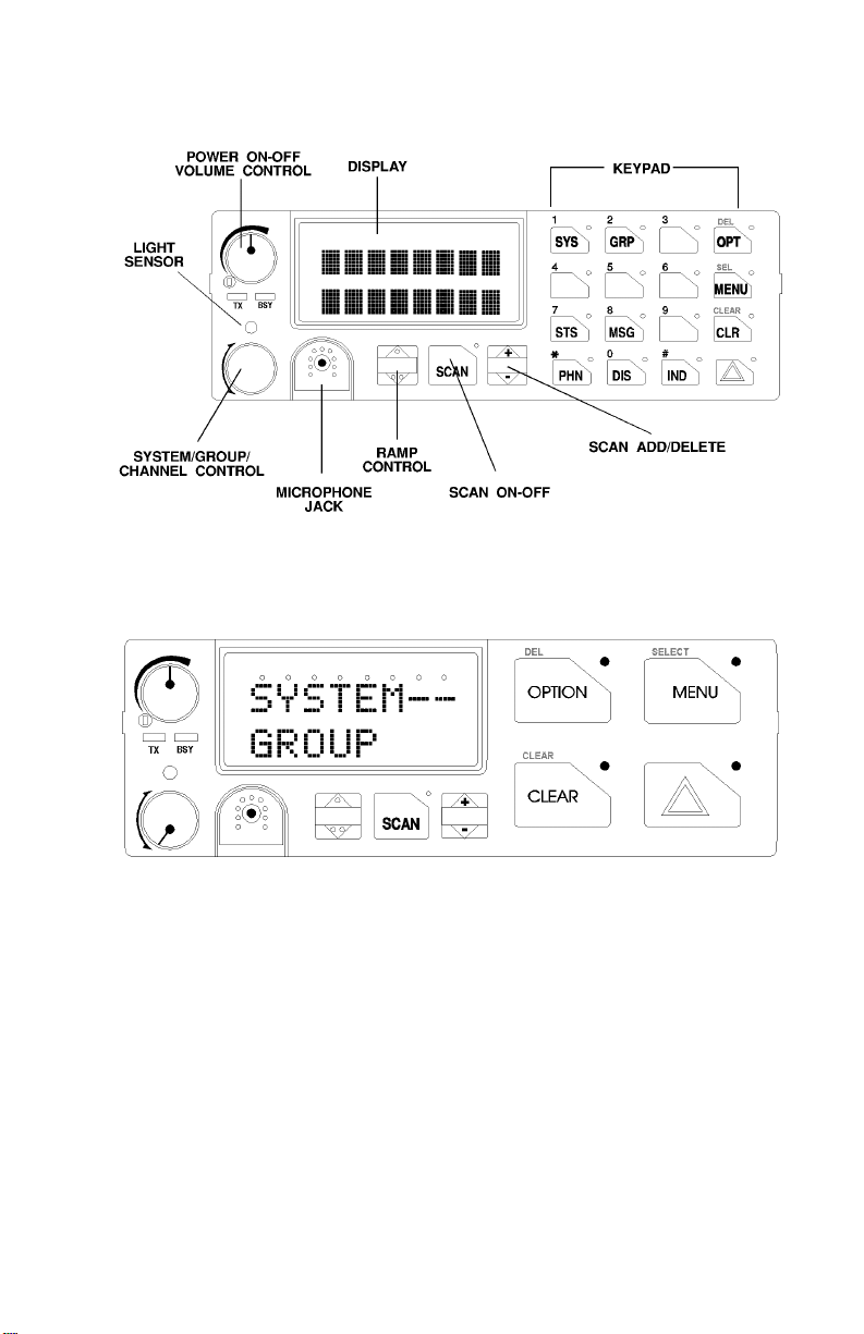
Figure 1 - ORION Mobile Radio SYSTEM Model Front Panel
Figure 2 - ORION Mobile Radio SCAN Model Front Panel
7
Page 8

CONTROLS
This section describes the buttons, keys and rotary knobs used to control the
Orion Scan and System Model radios. All functions and controls of the
Scan radio operate the same as the corresponding functions and controls on
the System radio. The Scan radio is equipped with a 4-button keypad and
the System radio is equipped with a 16-button keypad.
Many of the co ntr ol b uttons a nd keys have o r ca n be p rogr am med to have a
primary function and a secondary function. The SCAN button can be
programmed (as a secondary function) to toggle the keypad keys between
their primary function and their secondary function.
POWER ON-OFF VOLUME KNOB
This rotary Knob applies power to the radio and adjusts the
receiver volume. Rotating the control clockwise out of
detente applies power to the radio. A single alert tone
sounds (if enabled through programming) to indicate the
radio is operational.
Rotating the control clockwise increases the volume level. Minimum
volume levels may be programmed into the radio to prevent missed calls
due to a low volume setting. While adjusting the volume, the display will
momentarily indicate the volume level (i.e. VOL = 31). The volume range
is from a minimum level of zero (displayed as OFF in the display) up to 31
which is the loudest level.
SYSTEM/GROUP CHANNEL KNOB
This rotary knob selects the systems or groups/channels,
depending upon programming. This 16 position knob has
no stop. See SYSTEM/GROUP/CHANNEL
SELECTION for more details.
8
Page 9
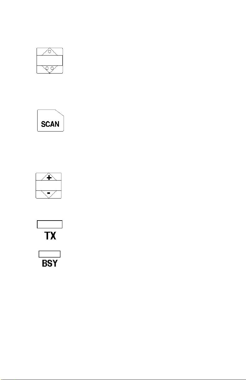
RAMP CONTROL
The primary function of this rocker type button is to scroll
through the System list or the Group/Channel list depending
upon programming. The secondary function is to increment or
decrement items within a list (phone list for example). Press
, to scroll in increasing order and press . to scroll in
decreasing order. To auto-ramp, press and hold the button.
SCAN ON/OFF
The primary function of this button is to toggle scan operation
on and OFF. When the radio is scanning, the SCAN LED is
on and all groups or channels in the scan list of the currently
selected systems are scanned.
The secondary function of the SCAN button is to toggle the keypad buttons
between their primary f unction and their secondary function.
SCAN ADD/DELETE
This rocker type button is used to display the current SCAN
status for a group/channel and then either add or delete the
group/channel from the system scan list.
INDICATORS
Transmitter enabled - ON when the radio is transmitting.
BuSY - On indicates a carrier is being received (the channel is
busy). Note that if the selected channel is programmed for
Channel Guard (CG), Digital Channel Guard (DCG) or Type
99 (T99) tone decode operation, the radio will not un-squelch
if a valid tone or code is not received; the BSY indicator will
be on.
9
Page 10
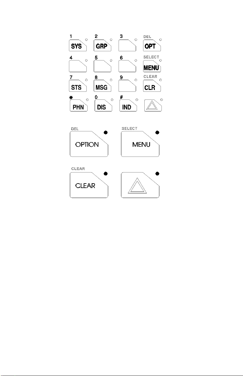
Figure 3 - ORION System Model Keypad
Figure 4 - ORION Scan Model Keypad
KEYPAD
The keypad is similar to a telephone keypad but with four (4) additional
buttons on the side for a total of 16 keys. In addition to numbers (1-9, *, 0
and #), which is a secondary function, most of the keys have or can be
programmed to have a primary function. A symbol or abbreviated word
describing its primary function is labeled on the keycap. Each labeled
keycap is associated with a radio feature (or primary function). The radio
must be programmed to operate with the Standard or the Optional keycap
configuration.
A keylight (LED) is associated with each key or button. This may light
when the associate function is active. In some conditions the keylight may
blink to indicate an action status.
The keypad ke y functions can be re mapped to any o f the primary fu nction
keys using the PC programming software. It is suggested that the blank
keypad (located at the back of this manual) be completed if the keypad key
functions are changed.
10
Page 11
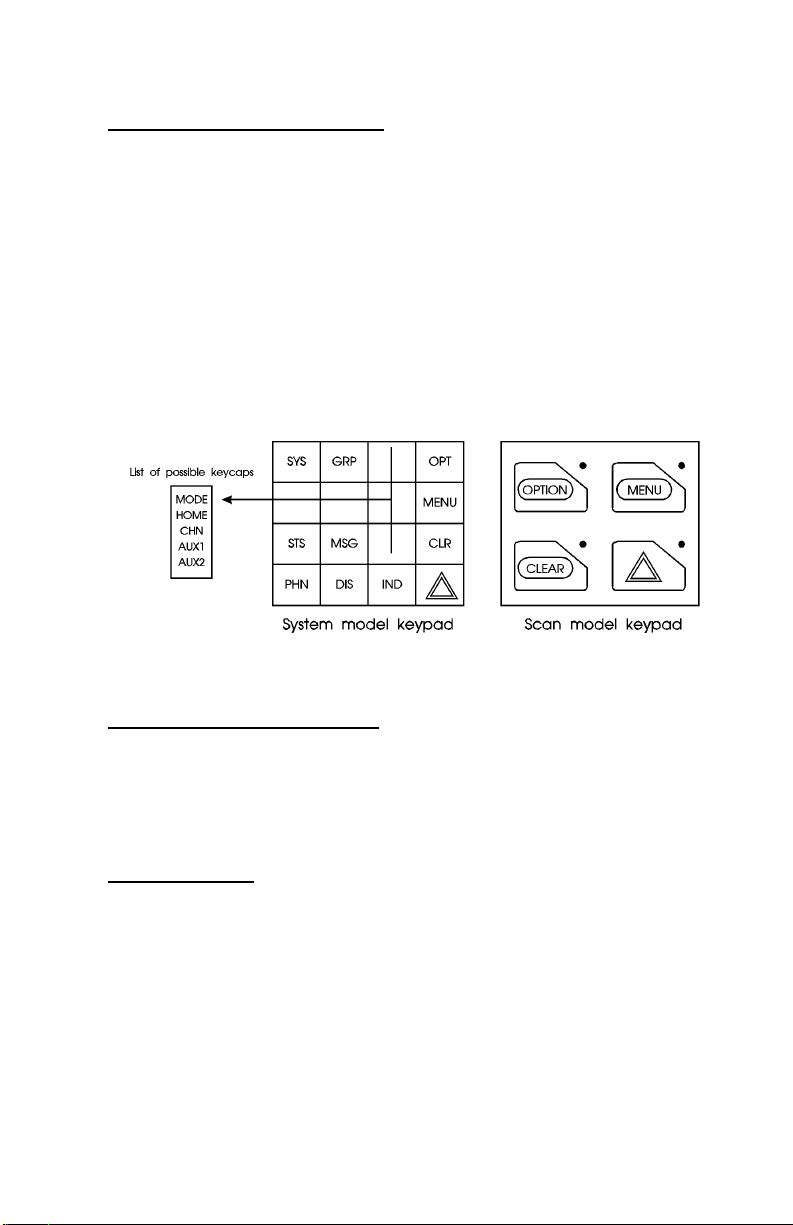
Standard Keycap Configurat ion
The Standard keycap package for the System radio includes five (5) labeled
keycaps (MODE, HOME, CHN, AUX1 and AUX2) and six (6) blank
keycaps, which can be placed on any of the five key locations (numbers 3-6
and 9) shown in Figure 5. The keycap represents the primary function
programmed for that key location. See the Key Description section for a
description of the primary function associated with these five (5) keycaps.
The Standard keycap package for the Scan radio includes five (5) labeled
keycaps [MENU, CLEAR, SELECT, EMERGENCY (
), OPTION] and
E
five (5) blank keycaps, which can be placed on any of the four (4) keypad
keys. The keycap represents the primary function programmed for that key
location.
Figure 5 - Standard ORION Keycaps Configuration
Optional Keycap Configuration
The Optional keycap package for the System radio includes sixty (60)
additional keycaps (shown in the Key Description section), which can be
placed on any key location desired. Keep in mind, the keycap represents
the primary function programmed for that key location.
Key Descriptions
MODE This key function is used to enter the Conventional System
selection mode.
HOME This key function returns the radio to the Home
System/Group where it is programmed.
CHN This key is used to enter the Channel select mode.
AUX 1 & 2
These keys are used to control output 1 or 2. Their
definition is PC programmable.
11
Page 12

S This key is used to enter the System select mode.
g
o
O
DEL Secondary function - used to delete a digit during numeric
m Primary function - accesses the menu list. This is a list of
SELECT Secondary function - activates a selected item within a list.
s The Status key permits the transmission of a pre-
n The Message key permits the transmission of a pre-
c
C
This key is used to enter the Group select mode.
This key function is used to toggle a PC programmable
feature ON and OFF.
entry (see SELECTION MODE RULES).
additional features that are not available directly from the
keypad. See MENU for details.
After the menus list is accessed, select a menu item from
the list via RAMP control , or . and activate it with this key.
Once activated, MENU continues its secondary function for
activating a selected parameter setting until the radio
returns to its normal receive state. This is similar to an
enter key.
programmed status message to an EDACS site.
programmed message to an EDACS site.
Serves several purposes depending on the operating mode.
In trunked mode, the CLR button exits the current operation
and removes all displays associated with it. The radio and
display then return to the group receive state. In
Conventional mode, pressing this button unmutes the
receiver so activity on the selected channel can be
monitored. When pressed and held for approximately 3
seconds, this button toggles conventional channel decod ing
(Channel Guard, Digital Channel Guard, T99) on and OFF
if programmed for the selected channel.
p
d
12
Used to place telephone calls through the radio by selecting
the interconnect special call function. See Telephone
Interconnect Calls for details.
Used to adjust the current display intensity and the keypad
backlight level.
Page 13

i Used to call individual or make an all-call by selecti ng the
individual call function. See Individual Calls for details.
E
This key function is used to declare emergencies.
ALM Toggles the external alarm ON/OFF. The external alarm is
used to indicate the radio is receiving an Individual Call.
Press the key once to enable external alarm and press again
to disable external alarm.
SG1-SG5 Corresponds to five (5) pre-programmed System/Groups.
Pressing a key programmed for SG1 would switch the radio
to the pre-programmed System/Group 1. Pressing a key
programmed for SG2 would switch the radio to the preprogrammed System/Group 2, etc.
WAIL, YLP,
RST, SL1SL8
The WAIL and YLP (Yelp) keys are designed to control an
optional Siren package. The SL1-SL8 (Siren/Li ght) keys
are designed to control an optional Siren/Light package.
The RST (Reset) key is used to turn all sirens and lights
OFF.
SPK This key function is used to toggle the external speaker
ON/OFF.
STO-ST9 The status 0-9 keys are used to send pre-programmed status
message to the EDACS site.
PVT Enables or disables Private Mode for the System/Group
displayed. See the PRIVATE OPERATION section.
KEY Displays the Encrypted Keys. This selects the DISP KEY
operation from the menu functions.
G* This key function is used in Conventional Mode to send
G-STAR emergency signalling.
PA This key function enables and disables the Public Address
feature.
# DTMF keypad function.
1-9 Keypad numbers.
* DTMF Keypad function.
Primary Functions (Quick Access)
The secondary function of the k button is to toggle the keypad buttons
between their primary function and their secondary function. When the
secondary keypad is active, i.e. entering phone digits for an interconnect
call, the
button can be used to toggle the keypad buttons back to their
k
primary function, perform a task (siren/light enable), and then toggle back
13
Page 14
to finish entering the digits for the phone number. PRIMARY is displa yed
when the
button is used to toggle the keypad keys back to their primary
k
functions. This provides quick access to the primary functions of the
keypad. This is a programmable feature of the
button only. Careful
k
consideration should be given to possible operational conflicts before
enabling this feature.
Several keys on the Sca n version have a se condar y function. T he
is the SELECT secondary function with the
for the secondary function. On t he sys t e m ve rsi o n, the
function for DELETE,
is SELECT and c retains its CLEAR
m
key remaini ng the same
C
has a secondary
o
m
key
function.
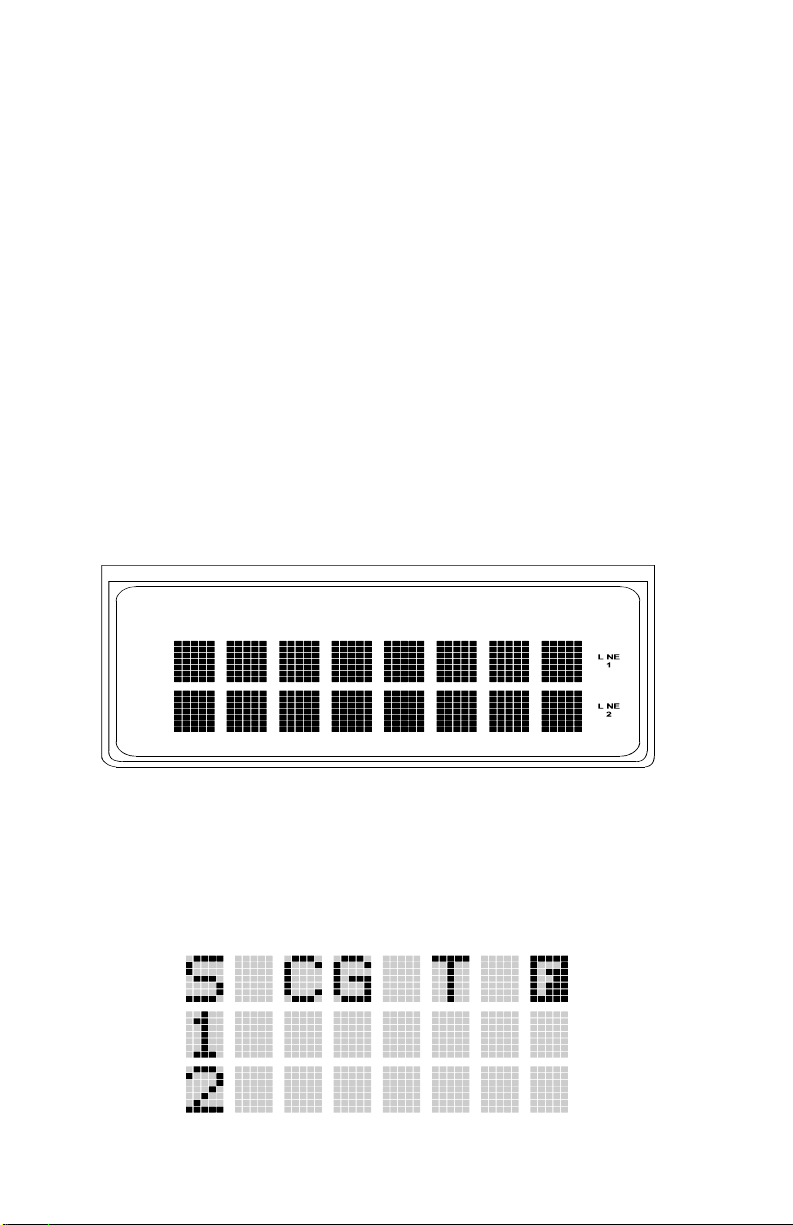
DISPLAY
The radio's display is shown in Figure 6. The two character lines are used to
display system, group and channel names and also operational messages to
the user. Each line contains eight alphanumeric character blocks. See
Figure 2 for a typical display.
Figure 6 - ORION Display
RADIO STATUS ICONS
Status icons are indicators which show the various operating characteristics
of the radio. The icons appear on the first line of the display.
14
Page 15
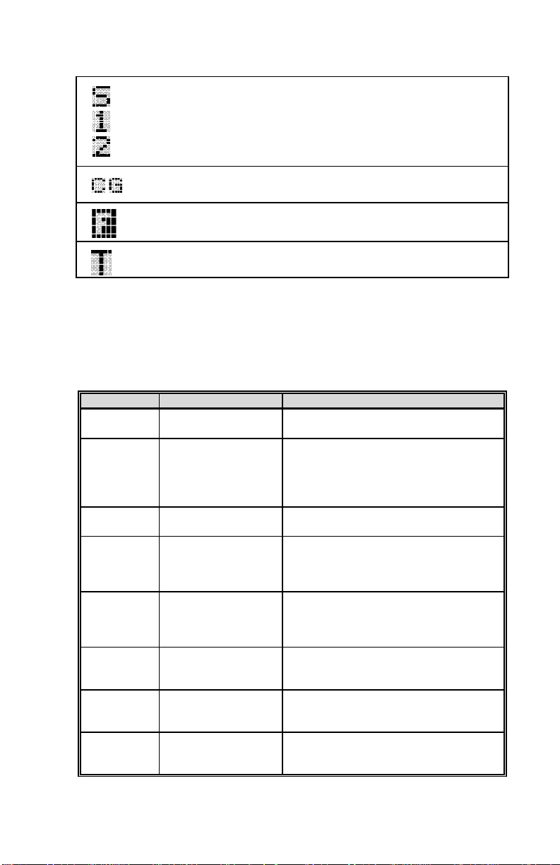
• indicates selected group or channel is in scan list.
• indicates selected group or channel is programmed as
Priority 1 in scan list.
• indicates selected group or channel is programmed as
Priority 2 in scan list.
indicates conventional channel enabled with Channel
•
Guard function.
• indicates the EDACS system is in failsoft mode (if
enabled through programming).
• indicates Type 99 Decode is enabled on a conventional
channel.
MESSAGES
During radio operation, various messages are displayed on either line one or
line two. Typical messages include control channel status information, such
as system busy or call denied, or messages associated with the radio's
operation, (i.e. volume adjust). These messages are described as follows:
MESSAGE NAME DESCRIPTION
QUEUED
SYS BUSY
DENIED
CC SCAN
WA SCAN
TALKARND
*RXEMER*
*TXEMER*
Call Queued Trunked mode only. Indicates the system has
placed the call in a request qu eue.
System Busy Trunked mode only. Indicates the system is
busy, no channels are currently available, the
queue is full or an individual call is being
attempted to a radio that is currently
transmitting.
Call Denied Trunked mode only. Indicates the radio is not
authorized to operate on the selected system.
Control Channel Scan Trunked mode only. Indicates the control
channel is lost and the radio has entered the
Control Channel Scan mode to search for the
control channel.
Wide Area Scan Trunked mode only. Indicates the control
channel is lost and radio has entered the Wide
Area Scan mod e to search for a new system
(if enabled through programming).
Talk-around Conventional mode only. Indicates the radio
is operating on conventional channels in talkaround mode (no repeater).
Receive Emergency Trunked mode only. Indicates an emergency
call is being received. This m essage will be
flashing on line two.
Transmit Emergency Trunked mode only. Indicates an emergency
call has been transmitted. This mes sage will
be flashing on line two.
15
Page 16

MESSAGE NAME DESCRIPTION
VOL=31
UNKNOWN
TX DATA
RX DATA
DATA OFF
DATA ON
SYSC ON
SYSC OFF
T99 ON
T99 OFF
NB ON
NB OFF
PA ON
PA OFF
ALRM ON
ALRM OFF
PVT DIS
FRCD PVT
NO KEY #
BCKL=1-6
Volume Level Indicates the current volume level. The
Caller's ID Not
Received
Transmit Data Trunked mode only. Indicates the radio is
Receive Data Trunked mode only. Indicates the radio is
Data OFF Trunked mode only. Indicates radio is in the
Data On Trunked mode only. Indicates radio has been
System Scan FeaturesOnTrunked mode only. Indicates the System
System Scan Features
OFF
Type 99 Decode On Conventional mode only. Indicates the Type
Type 99 Decode OFF Conventional mode only. Indicates the Type
Noise Blanker On Conventional mode only. Indicates noise
Noise Blanker OFF Conventional mode only. Indicates noise
Public Address On Indicates that the public address function of
Public Address OFF Momentary (2 seconds) indicates that public
External Alarm Enabled Indicates that the external alarm function of
External Alarm
Disabled
Private Mode Disabled Indicates that private mode is disabled or no
Forced Private
Operation
Encryption Key
Missing
Backlight Display intensit y and keypad back light level.
volume level display ranges from OFF
(silent) to 31 (loudest).
Indicates that an individual call is being
received, but the caller's ID was not received.
transmitting a data call.
receiving a data call. Displayed on li ne 2.
data disabled state. Displayed on line 1.
toggled to the da ta en able st ate. Di splayed for
two seconds on line 1 when toggled t o enab le
state.
Scan features are enabled.
Trunked mode only. Indicates the System
Scan features are disabled.
99 Decode feature is enabled.
99 Decode feature is disabled.
blanker feature is enabled on low band (29-50
MHz) version.
blanker feature is disabled on low band (2950 MHz) version.
the radio is enabled.
address function of the radio was disa bled.
the radio is enabled.
Momentary (2 seconds) indicates that external
alarm function of radio was disabled.
encryption key has been programmed for the
selected group/channel or special call.
Indicates that forced private operation has
been pre-programmed into radio.
Flashing indicator indicates that no
encryption key or an incorrect encryption key
is programme d into the radio.
16
Page 17

MESSAGE NAME DESCRIPTION
GR
ID
WHC=1
PHONE
CONV FS
MENU
SYS=1-64
GRP=1-64
INDV=1-99
PHN=1-99
Group ID Th is ind icates that the c all is a group call and
is followed by the GID of t he caller (tru nked
mode only).
Individual ID This indicates the call is an individual call
and the ID number of the caller, example "ID
2725" (trunked mode only).
Who Has Called This display indicates the number from the
Who Has Called list. Individu al ca lls recei ved
but not responded to are stored in a Who Has
Called list. This list is accessible by pressing
the # key and then the INDV key after the
Individual call has timed out or the Clear
button is pressed. This display is on line 2 and
the LID of the caller is displayed on the top
line. Currently the list is not implemented and
the display will always be WHC=1.
Phone Call Displayed when a phon e call is recei ved from
the site. It is displayed in line one of the
display. Line 2 of the display will contain the
display *INDV*" when line 1 contains this
message. The radio interprets a received
phone call as an individual call.
Conventional Failsoft Displayed when a failure of the EDACS
system occurs. All communication will be in
conventional mode (trunked mode only).
Displayed when the menu key is pressed and
remains disp layed in line 1 u ntil one chooses
a menu item.
System = 1 - 64 This is the system number for the current base
station of the system displayed in line 1. It is
displayed in line 2 of the display. Press the
system key to obtain this display.
Group = 1 - 64 This is the group number of the group
displayed in lin e 2 of display. It is d isplayed
in line 1 of the dis pla y. Press th e grou p k ey to
obtain this disp lay. Ther e are up to 48 groups
available (i.e. 3 banks of 16). The maximum
groups programmed in a radio is determined
by the personality.
Individual = 1 - 99 This display indicates which item in the
individual call list is being displayed. It is
displayed in line 2 of the displa y. The name
or ID of the item in the list is displayed in line
1 of the display.
Phone = 1 - 99 This display indicat es which item in the
phone list is being displaye d. I t is displayed in
line 2 of the display. Line 1 of the display will
be the last 3 characters of the list item
contents.
17
Page 18

MESSAGE NAME DESCRIPTION
SEL PHN
SEL INDV
SYS ALL
Ggg-v.vv
*PHONE* Phone Call This is displayed when an in itia ted phon e call
DUAL
NO ENTRY
INV SYS
CHN=1-99
FIX LIST
FIXED P1
(c) 1995
EM
*INDV*
*GROUP*
Select Phone After pressing the PHN key, selecting an
Select Individual ID This is displayed on line 1 when an entry
System All Call Displayed on line 1 to indicate a system a ll
Code Group and
Revision Number
Dual Control Operation Displayed on idle control unit when
Invalid System Displayed when the current system is an
Channel = 1 - 99 This is displayed on line 1 of the display is
Fixed List Priority scan list is fixed and cannot be
Fixed Priority 1 Priority 1 scan channel is fixed and cannot be
Emergency This indicates an emergency has been
Individua l Call This i s disp la yed in line 2 of th e di sp lay when
Group Call This indicat es a group call is in progress and
entry from the phone list by typing the entry
number will display this message on Line 1.
from the individual ID list is selected after
pressing t he INDV key. The entry is a number
between 1 and 32 inclusive (trunked mode
only).
call has been received (trunked mode only).
This is code group and revisi on number that
is displayed in line 2 when menu item
"REVISION" is selected. The `gg' is the
group number of the software. The first `v' is
the hardware version. The last two, `vv', is the
revision of the software.
is in progress. Thi s is displayed on line 2 of
the display .
configured as dual control operation.
This indicat es that there is no data stored in
one of the programmab le items in either the
phone list or individual call list. The user
programmable items are items 1 through 10 in
each list.
invalid type .
conventional channel index when the group
key is depressed.
changed using ad d an d delete keys.
changed using ad d an d delete keys.
This is displa yed in line 2 when the message
"ERICSSON" is displayed in line 1 of the
display while displaying different items under
menu when `REVISION' is selected by the
operator.
declared by the LID that follows the display,
`EM'. An example of th is is "EM 01201".
an individual call is in progress (trunked
mode and T99 mode only).
is displayed on lin e 1 of the display (trunk ed
mode and T99 mode only).
18
Page 19

MESSAGE NAME DESCRIPTION
SPKR ON
SPKR OFF
BANK=1-8
REGR_0x
KEY LOAD
KEY ZERO
SYS KEY
GRP KEY
CHN KEY
KEY=1-7
PRIMARY
PRS NAME
ERICSSON
External Speak er On Thi s is disp layed when the ext erna l sp eak er is
enabled.
External Speaker OFF This is displayed when th e extern al s peak er i s
disabled.
This is the bank of keys which are going to be
loaded when th e key loader load s encryption
keys. This is only valid for radios which
support VGS, VGE, or DES encrypti on. It is
displayed on lin e 2 of the display when th e
encryption key loader is connected.
Dynamic Regroup Indicates which group in dynamic regroup
operation has been enabled where "x" is a
digit of 1 to 8 (trunked m ode only).
This is displa yed in lin e 1 of th e disp la y when
the encryption key loader is connected.
This is displayed on line 2 of the display
when the operator depresses the reset and
option buttons simultaneously for
approximately two seconds. The encryption
keys are zeroed.
System Key This is disp layed on line 1 of th e display in
the display key mode of the menu. The key of
the key name display is displayed in line 2.
Group Key This is displayed on line 1 of the display in
the display key mode of the menu for trunked
systems only. It is followed in the second line
with a key number `KEY = <1..7>'.
Channel Key This is displayed on line 1 of the display in
the display key mode of the menu for
conventional systems only. It is followed in
the second line with a key number `KEY =
<1..7>'.
This is displayed on line 2 of the d isplay in
the display key mode of the menu for
conventional when `SYS KEY' or `CHN
KEY' are displayed in line 1 and for trunked
when `SYS KEY' or `GRP KEY' are
displayed in line 1.
This is displayed on line 1 of the display
when primary keys are enab led.
Personality Name This is displayed in line 1 of the display under
the revision selection of menu. The
personality name is displayed on line 2 at the
same time.
This is displayed on line 1 of the display
under the revision selection of menu. The
copyright year is shown in line 2 of display at
the same time.
19
Page 20

ALERT TONES
The ORION radio also provides audible alert tones or "beeps" to indicate
the various operating conditions. These alert tones can be enabled or
disabled through programming.
CALL ORIGINATE
A short mid-pitched alert tone sounds after keying the radio (Push-To-Talk
button is pressed). This indicates the radio has been assigned a working
channel or that the radio is transmitting on a conventional channel and voice
communication may begin immediately. In conventional mode, this tone
may be delayed after the PTT button is pressed d ue to G-STAR signalling
(if enabled through programming).
AUTOKEY (TRUNKED MODE ONLY)
After being placed in queue or releasing the PTT button prior to a working
channel assignment, the site calls the radio when a channel becomes
available. At this point, the radio automatically keys the transmitter
(autokey) for a short period to hold the channel. The radio sounds a midpitched tone when it is clear to talk; immediately press the PTT button to
keep the assigned channel.
CALL QUEUED (TRUNKED MODE ONLY)
A high-pitched tone after pressing the PTT button indicates the system has
placed the call request in the queue. The receiving unit(s) also hear the
tones, indicating they will receive a call shortly. If the PTT button is
released, the radio will autokey whenever a channel becomes available (see
Autokey).
SYSTEM BUSY (TRUNKED MODE ONLY)
Three low-pitched beeps will be heard if the radio is keyed when the system
is busy, if no channels are available for sending the message, if the call
queue is full, or if an individual call is being attempted to a radio that is
transmitting. Releasing the PTT button and rekeying initiates a new channel
request.
20
Page 21

CALL DENIED (TRUNKED MODE ONLY)
If the radio is keyed and a low pitched tone is heard then the radio is not
authorized on the system that has been selected.
CARRIER CONTROL TIMER
If the programmed time for continuous transmission is exceeded, five short
high-pitched warning tones followed by a long low-pitched tone will be
heard. The transmitter will shut down shortly after hearing the alert,
interrupting communications. Release and re-key the PTT button to
maintain communications. This will reset the carrier control timer and turn
the transmitter back on.
KEY PRESS ALERT
A short tone or " beep" sounds to indica te a key has been pr essed. A short
low-pitched tone indicates no action was taken because the key is not active
in the current mode.
DUAL CONTROL SWITCHING
When control is switched to a previously idle control unit, two short highpitched tones will sound at the control unit where PTT was pressed, that is
now the active controller.
OPERATION
The ORION mobile radio unit can be programmed to operate in either a
trunked system or a conventional system or both. Operating features and
functions have been grouped according to the type of system the radio is
operational. This first section contains general operating procedures (e.g.,
Turning On The Radio). The second section, TRUNKED MODE
OPERATION, covers those operating procedures that are only used in a
trunked system (e.g., Group Scan). The third section, CONVENTIONAL
MODE OPERATION, covers those operating procedures that are only
used in a conventional system (e.g., Squelch Adjust). The fourth section,
TRUNKED OR CONVENTIONAL M ODE OPERA TION, covers those
operating procedures that may be used in either a trunked or conventional
system (e.g., Multiple Radio Operation).
21
Page 22

TURNING ON THE RADIO
Rotate the POWER ON-OFF/VOLUME knob clockwise, out of detente to
turn the radio on. A short beep (if enabled through programming) indicates
the radio is ready for operation. The display indicates, if programmed, the
last selected system name on line one and the last selected group or channel
name on line two.
In the EDACS trunked environment, if communication with the system's
control channel cannot be established, the CC SCAN message will be
displayed. This may occur if, for example, the radio is out of range of the
trunking site. It may be necessary to move to another location or select
another trunking system to re-establish the control channel link for trunked
mode operations.
SELECTION MODE RULES
Many operations require selection from a list such as system, group or
phone number. This selection process is handled in the same manner for all
lists. The RAMP control , and . , SEL, 0-9, *, #, the DEL button and
the
example systems list is used to explain the process:
button are used during the selection process. The following
c
NOTE
The hookswitch functions the same as the c key in I-Call, phone
call, and menu modes.
The following example systems list is used to explain the process:
SYSTEM
1 NORTH
2 SOUTH
3EAST
4WEST
After entering a selection mode, the following generic display format will
appear.
X X X X X X X X
Y Y Y = Z Z Z
22
Page 23

Line one shows the currently selected item name (XXXXXXXX) from the
list. Line two indicates the list (YYY) that the selection is to be made from
and the number of the selected item (ZZZ) within the list. (In some cases
the information on lines 1 and 2 will be exchanged. Enter the system
selection mode by pressing the
selection, the display appears as follows:
S Y S = 2
Line one contains the current system name, SOUTH, and line two, SYS = 2,
indicates that selection is from the system list and it is the second syste m
within the list.
A new system from the list is selected by using the RAMP control , or
or by directly entering the system number with the numeric keys. The
.
key. If SYSTEM 2 is the current
S
S O U T H
RAMP control , or
decreasing order. In the previous example, pressing the RAMP control ,
selects the EAST system as shown in the next display.
The radio may be programmed to wrap around from one end of a list to the
other end or to stop at the ends.
scrolls through the list in increasing and
.
E A S T
S Y S = 3
DIRECT ACCESS
To directly access a selection, enter the corresponding number (i.e. 4)
followed by SEL to activate the selection. The entered number is displayed
on line two as shown below. Line one shows the current list being used for
selection.
S E L S Y S
4
23
Page 24

If a mistake is made while entering the number, press the DEL button to
backspace once and correct the entry. If an invalid number is entered, a
short low-pitched tone sounds when SEL is pressed.
To exit the selection mode, press the
button or wait for the time-out. If
c
the selection mode is cleared while an entry is pending (i.e., numbers are
entered on line 2, but SEL has not been pressed), the entry on line two will
be disregarded and the previous selection will remain active. If the time-out
activates while an entry is pending, the entry on line two will be selected if
it is within the valid range; if it is out of range, the entry on line two will be
disregarded and the previous selection will remain active.
NOTE: While in system, group or channel selection mode, the radio
continues to receive calls normally and continues scanning if it is enabled.
If a call is received during the selection mode process the radio will return
to the normal receive mode display. Continuing with the selection process
will return the display to the same point in the selection process if the
selection mode time out has not yet expired. An y press of the PTT button
during the selection mode process will initiate transmission and exit the
selection mode.
MENU
The menu function accesses features that are not available directly from the
keypad. The order and specific number of menu items available is
configurable through programming. Upon radio power up, the menu item
that is at the beginning of the menu list will always be displayed first.
Subsequent access to the menu function will return the last menu item that
was shown in the display. To enter the menu mode, press
. The RAMP
m
control , and ., the SEL and the
buttons are used during the
c
selection process. All of the selection mode rules previously detailed apply
to the menu item selection process with the exception of direct access. The
radio will continue to receive and transmit normally while in the menu
function.
A new item is displayed by using the RAMP control , and . to scroll
through the list in increasing and decreasing order. The displayed menu
item is made active by pressing SEL.
24
Page 25

After entering the menu selection mode, the following generic display
format will appear.
M E N U
Y Y Y Y Y Y Y Y
Line one indicates the radio is in the menu selection mode. Line two
indicates the menu item (YYYYYYYY) that is to be viewed or changed
(some menu items provide radio information and do not have changeable
parameters).
An example of the menu item selection process and menu item parameter
change is detailed below for the backlight menu item.
PRESS:
m
The menu mode is entered.
PRESS: The RAMP control , and . until the display shows:
M E N U
B C K L G H T
PRESS: SEL
The backlight menu item is activated and the display will be similar to the
following:
B C K = X X X
Y Y Y Y Y Y Y Y
Line one shows the active menu item and its current parameter setting
(XXX). Line two shows the currently selected system or group name
(YYYYYYYY).
The menu item's parameter setting shown in the display can now be
changed by using the RAMP control , and . to scroll through the list
of parameter values. Once the desired setting is reached press SEL to store
the value and return the normal display. For menu items that display radio
information pressing , and . will scroll through a list of i nformational
displays. The menu items are listed Table 1.
25
Page 26

TABLE 1 - MENU ITEM INFORMATION
FEATURE DISPLAY PARAMETER
Backlight Adjust Menu Item:
Radio Revision
Information
Noise Blanker Menu Item:
PHONE CALL Menu item:
Individual Call
(Trunked Systems
Only)
External Alarm Menu Item:
PUBLIC
ADDRESS
EXTERNAL
SPEAKER
Encryption Key
Loading
Display Current
Encryption Key(s)
BCKLIGHT
Once selected:
BCKL=
Menu item:
REVISION
NOISBLKR
Once selected:
NB ON or
NB OFF
PHN CALL
Once selected: See
Telephone Interconnect
Call Section
Menu Item:
IND CALL
Once Selected: See
Individual Call Section
EXTALARM
Once Selected:
EXTALARM
Menu item:
PUB ADDR
Once selected:
PA ON or
PA OFF
Menu item:
EXT SPKR
Once selected:
SPKR ON or
SPKR OFF
Menu item: KEYLOAD
Once selected:
KEY LOAD BANK = N
Menu item:
DISP KEY
Once selected:
SYS KEY, GRP KEY or
CHN KEY and KEY = N
SETTINGS
OFF, 1, 2, 3, 4 Selects the light
Informational
displays only
(see radio); no user
selectable settings.
ON, OFF Noise Blanker
ON, OFF EXTALARM
ON, OFF Public Address is
ON, OFF External Speaker is
Up to 8 banks of 7
keys
COMMENT
level for
backlighting.
Selects the
information display
to view.
function toggled on
and OFF.
Allows access to the
Phone Call Feature.
Allows access to the
Individual Call
Feature.
replaces the system
name on the display
as long as the
external alarm
feature is enabled.
toggled on and OFF.
toggled on and OFF.
Enables th e r adio to
accept the loading of
encryption keys.
Displays current
encryption key
number.
26
Page 27

FEATURE DISPLAY PARAMETER
Front Panel
Squelch Adjust
(Conventional
Only)
Scan Menu item: SCAN ON, OFF Toggles scan
Private Mode Menu Item:PRIVATE
Scan Add Menu item: SCAN ADD
Scan Delete Menu item: SCAN DEL
Scan Add/Delete Menu item: SCAN A/ D
Home group or
channel selection
System select Menu item: SYS SEL
External alarm #2 Menu item: EXTALRM2 ON, OFF Toggles external
System and group
selection
Mute Menu item: MUTE ON, OFF Toggles the mute
Mute #1 Menu item: MUTE 1 ON, OFF Toggles the mute 1
Mute #2 Menu item: MUTE 2 ON, OFF Toggles the mute 2
Multiple radio
operation
Menu item:
SQUELCH
Once selected:
SQLCH=xx
Once selected: PVT or
key light.
Once selected: Proper
scan icon displayed .
Once selected: Scan icon
goes out.
When selected: Toggles
through scan selections
Menu item: HOME
Once selected: Home
group or channel
displayed.
Once selected: SYS = n
Menu item: SYSGRP 1
Menu item: SYSGRP 2
Menu item: SYSGRP 3
Menu item: SYSGRP 4
Menu item: SYSGRP 5
Menu item: RADIO ON, OFF Toggles the
SETTINGS
1-16 Allows setting of
ON, OFF Toggles pri vate
S, 2 or 1 Adds group or
Toggle sequence
S, 2, 1, S, ...
1-64 = (n)umber of
desired system
COMMENT
squelch.
function on or OFF.
function on or OFF.
channel to scan list.
Deletes group or
channel from scan
list.
Changes pr esent
group or channel to
next scan choice in
scan list.
Changes to the
group or channel
defined for Home
function.
Displays the system
selected.
alarm #2 feature on
or OFF.
Changes to the
System &
Group/Channel
programmed for
SYSGRP 1-5.
function on or OFF
to control the audio
output from the
selected radio.
function on or OFF
on radio #1.
function on or OFF
on radio #2.
currently selected
radio.
27
Page 28

FEATURE DISPLAY PARAMETER
Radio selecti on Menu item: RADIO 1 ON, OFF Changes to radio #1.
Menu item: RADIO 2 ON, OFF Changes to radio #2.
No Data (Trunked
System Only)
EDACS/Conventio
nal Channel 1 Scan
(Trunked System
Only)
Group selection
(Trunked System
Only)
Status Condition
(Trunked System
Only)
Message Condition
(Trunked System
Only)
Talkaround feature
(Conventional
System Only)
Channel selection
(Conventional
System Only)
Feature Encryption
Display
System Scan Enable Menu Item:
Type 99 Decode
Enable
Menu item: NO DATA ON, OFF Toggles da ta feature
Menu item: ECP1SCAN ON, OFF Toggles this feature
Menu item: GRP SEL
Once selected: GRP = n
Menu item: STATUS
Once selected: ST =n
Menu item: ME SSAGE
Once selected: MSG =n
Menu item: TALKARND
Once selected:
TALKARND on line 1
Menu item: CHN SE L
Once selected: CHN = n
Menu Item:
FEATURES
Once selected:
See Feature Encryp t ion
Display section
SYS SCAN
Once selected:
SYSC ON or SYSC OFF
Menu Item:
T99 ENAB
Once selected:
T99 ON or T99 OFF
SETTINGS
1-64 = (n)umber of
desired group
0-9 = (n)umber of
pre-programmed
status
0-9 = (n)umber of
pre-programmed
messages
ON, OFF Toggles selected
1-99 = (n)umber of
desired channel
Informational
displays only; no
user selectable
settings
ON, OFF System Scan
ON, OFF Type 99 Decode is
COMMENT
on or OFF.
on or OFF.
Displays the grou p
selected.
Transmits the preprogrammed status
message.
Transmits the preprogrammed
message.
talkaround channel
on or OFF.
Displays the
conventional
channel selected.
Indicates current
features programmed into the radio as
well as certain
information required
to add features to the
radio (refer to the
Table of Contents
for Feature
Encryption Display.
features are toggled
on and OFF.
toggled on and OFF.
28
Page 29
FEATURE ENCRYPTION DISPLAY
Feature Encryption Display is available through the menu function and, if
programmed, appears in the menu as "FEATURES." This data indicates
current features programmed into the radio as well as information required
to add features to the radio. This feature applies to 512K RAM radios only.
Once the feature has been accessed, all normal menu functions work. The
user can scroll up or down through all of the entries.
Feature Encryption Display provides the ability to view, in the order
displayed, the following:
Serial number ROM data - serial number of the ROM
•
Feature encryption data stream - used to enable features
•
Number Fields - defines limits
•
Features enabled - displays bit fields of enabled features
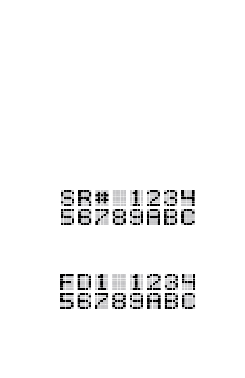
•
Serial Number ROM (12 Hex Digits)
Example:
When the user wants to enable a feature in his radio, he will need to call
M/A-COM. They will ask for the ROM serial number. The serial number
shown here is for example only.
Feature Encryption Data Stream
Example:
These data streams define the features the user has enabled in his radio and
are required by M/A-COM to enable other features. The data streams shown
here are for example only. Note: There are three displays: FD1, FD2, FD3.
All three are required.
29
Page 30
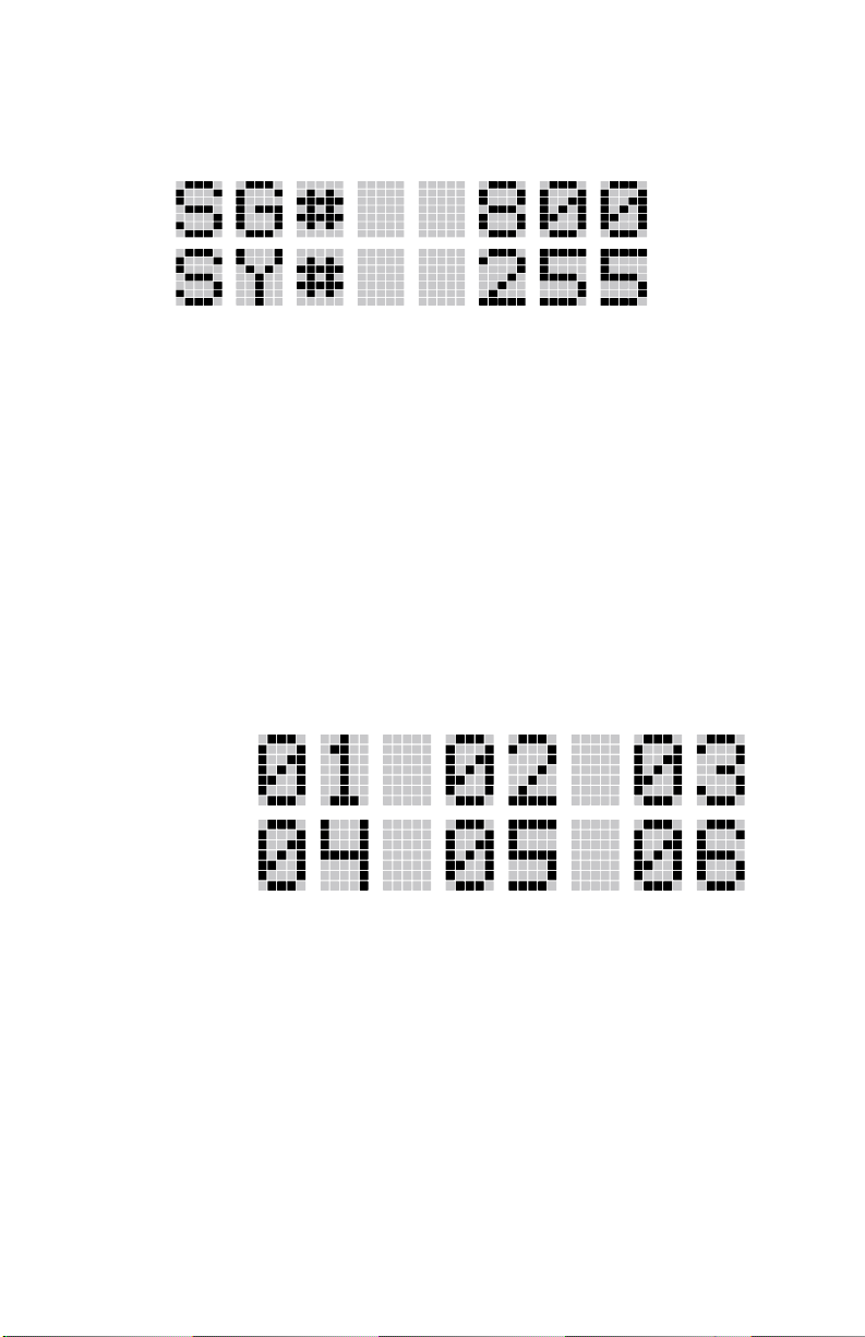
Number Fields
Example:
These number fields show the set limits of the of the user's radio as:
SG# XXX - Maximum number of system/groups combination
•
available
SY# XXX - EDACS maximum trunked system limit
•
CH# XXX - Maximum number of conventional channels available
•
The user needs to know the limits of his radio before attempting to enable
other features. The numbers shown here are for example only.
Features Enabled
These numbers indicate which features are enabled.
Example:
30
Page 31

The following numbers indicate features available in the user's radio.
BIT FIELDS POSSIBLE FEATURES
01 Conventional mode Priority Scan
02 EDACS 3 Site System Scan
03 Public Address operation
04 EDACS Group Scan operation
05 EDACS Priority System Scan
06 ProSound/ProScan
07 EDACS Dynamic Regroup operation
08 EDACS Emergency Operation
09 Type 99 Encode
10 Conventional mode Emergency operation
11 RF Pre-amp enable
12 AEGIS Digital Voice operation
13 VGE encryption
14 DES encryption
15 User-defined speech encryption
16 Mobile Data operation
17 Status and Message operation
18 Test Unit Operation
21 Alternate Language Operation
22 Over The Air Personality Programming (ProFile)
23 Narrow Band Operation 12.5 kHz Channel Spacing
29 ProVoice Operation
31
Page 32

SYSTEM/GROUP/CHANNEL SELECTION
In the following description of SYSTEM/GROUP/CHANNEL
SELECTION, the term group is used for both group and channel.
The ORION SYSTEM/GROUP/CHANNEL knob and the RAMP control
,, .
SYSTEM/GROUP/CHANNEL knob is assigned to select groups, then the
RAMP control ,,
SYSTEM/GROUP/CHANNEL knob is assigned to select systems, the n the
RAMP control ,, . keys are assigned to select groups. System, group
and channel selection is the primary function for these controls.
Either systems or groups can also be selected by entering the select mode
and following the selection mode rules described earlier. The system select
or group select modes are entered by pressing SYS or GRP, respectively,
from the standard receive mode. Using the RAMP control, , . after
entering a particular selection mode in this manner is the secondary function
of these keys.
System Selection
Several methods, some of which depend on programming, can be used to
select a new system. These procedures are presumed to be starting from the
normal receive display.
METHOD 1
METHOD 2
pair are programmable for maximum flexibility. If the
is assigned to select systems. If the
.
If system selection is programmed to the SYSTEM/
GROUP/CHANNEL knob, select a system by turning the
SYSTEM/ GROUP/CHANNEL knob to the de sired system
position. The display registers the ne w syste m na me o n li ne
one. If the wrap option is OFF and the knob is moved to a
position greater than the number of programmed systems,
the highest programmed system will remain selected.
If system selection is programmed as the primary function
32
of the RAMP control , and ., select a system by
pressing , or . to scroll through the system list. The
display registers the new system name on line one.
Page 33

METHOD 3
Press
to enter the system select mode and follow the
S
selection mode rules detailed earlier. Presses of the RAMP
control , or . will now scroll through the systems.
Group And Channel Selection
Several methods, some of which depend on programming, can be used to
select a new group or channel. These procedures are presumed to be starting
from the normal receive display.
METHOD 1
If group selection is programmed to the SYSTEM/GROUP/
CHANNEL knob, select a group by turning the SYSTEM/
GROUP/CHANNEL knob to the desired group. The
display registers the new group name on line two. If the
wrap option is OFF and the knob is moved to a position
greater than the number of programmed groups, the highest
programmed group will remain selected.
METHOD 2
If group selection is programmed as the primary function of
the RAMP control , and ., selects a group by
pressing , or ., to scroll through the group list. The
display registers the new group name o n l ine two.
METHOD 3
Press
to enter the group select mode and follow the
g
selection mode rules detailed earlier. Presses of the RAMP
control will now scroll through diffe rent groups.
33
Page 34

TRUNKED MODE OPERATION
Digital trunking provides fast communication access at all times, even
during busy hours. In this mode the operator selects a communications
system and group and the audio communication or working channel (WC)
is allocated through digital signalling with the site.
RECEIVING A CALL
1. Turn on the radio by rotating the POWER ON-OFF/VOLUME knob
clockwise (out of detente). A short alert signal (if enabled through
programming) indicates the radio is ready to use.
2. The display shows the last selected or the power up (depending on
programming) system and group names. If the radio is unable to obtain a
control channel, line two shows CC SCAN.
3. Adjust the POWER ON-OFF/VOLUME knob to the desired volume
level.
4. Select the desired system and group. The display indicates the current
system and group names.
5. The radio is now ready to receive calls.
6. When the radio receives a group call, it unmutes on the assigned
working channel and BSY indicator comes on. Line one shows GR
followed by the logical ID number (if received) of the unit sending the
message, or the associated name if the ID number is found in the
individual call list.
SENDING A CALL
1. Turn ON the radio and set the POWER ON-OFF/VOLUME knob to the
desired volume level. Select the desired system and group.
2. Press and hold the PTT button. The radio will display the system and
group names and perform the necessary signalling required to obtain a
communication channe l .
3. When the working channel is assigned, TX and BSY indicators are
turned ON and a short beep sounds indicating that communication can
begin. (NOTE: If two or more tones, or a high pitched tone is heard, the
system may be busy and the call request has been placed in queue or the
request has been denied for some reason. Refer to the ALERT TONES
section for more details).
34
Page 35

4. Hold the microphone approximately three inches from the mouth and
speak in a normal voice.
5. Release the PTT button when the transmission is complete and listen for
a reply.
CONVENTIONAL FAILSOFT
In the unlikely event of a failure of the EDACS System, communications
may take place in conventional failsoft mode. The radio will be
automatically directed to a communications channel set up for this purpose.
During this mode of operation, the control unit will display CONV FS in
the alphanumeric display. An increase in activity on the channel during
conventional failsoft operation may be noticed, so be careful not to transmit
until the channel is clear.
Operation during conventional failsoft will be the same as operation on a
conventional system, except that it will not be possible to select a
communications channel, or use emergency and special call. When
trunking is restored, the radio will automatically be returned to normal
operation.
NOTE
Emergency and Special Call are not operational during conventional
failsoft. Also, the GROUP control will not operate.
EMERGENCY OPERATION
The radio's ability to declare an emergency, clear an emergency, remain
locked on an emergency and group, and the emergency audio and display
freeze can each be enabled or disabled through programming. When an
emergency is declared scanning will stop and restarts only after the
emergency has been cleared.
Receiving An Emergency Call
When receiving an emergency call from the selected group and system, an
alert beep is heard and the BSY indicator comes ON. The message
*RXEMER* flashes in the display on line two until the emergency
condition is cleared. Follow standard emergency procedures.
35
Page 36

Declaring An Emergency Call
To send an emergency call to the selected system and group (or on an
optionally pre-programmed emergency group), proceed as follows:
1. Press and hold the red
button for approximately one second (this
E
time is programmable and therefore could be longer or shorter; check
with the system administrator). The radio will transmit an emergency
call request with the radio ID until an emergency channel assignment is
received.
2. When the working channel assignment is received, the radio sounds a
single beep (Autokey alert tone) indicating it is ready for voice
transmission. *TXEMER* flashes on line two in the display until the
emergency is cleared.
3. Press PTT and speak into the microphone in a normal voice.
4. Release PTT when the transmission is complete and listen for a reply.
5. The emergency can be cleared by pressing and holding the
followed by pressing the
button then releasing both buttons.
E
c
button
SYSTEM SCAN OPERATION
The radio can be programmed with the following System Scan features.
These features are automatically enabled upon radio power up. A key or
menu option is also defined to allow the Syste m Scan features to be toggled
during radio operation. This is covered in the Menu Selection and PreProgrammed Keypad Key sections. The System Scan state will be
maintained through system changes but will default to ON at power up.
Wide Area System Scan
The ORION radio may be programmed for wide area system scan
operation for multi-site applications. Upon the loss of the currently selected
system's control channel, radios may be programmed to automatically scan
the control channels of other systems. If a new control channel is found, the
radio will switch to the new system and sound an alert tone.
36
Page 37

ProSound
TM
The radio may be programmed for ProSound system scan operation for
multi-site applications. ProSound is an enhanced multi-site system
scanning algorithm, compared to Wide Area System Scan. ProSound
provides the radio with the ability to select a new system for the radio to
communicate on, when the selected system drops below a predefined level.
This is accomplished by enabling each radio to analyze the signal quality of
its current control channel and compare it with the signal quality of the
control channel for each site in its adjacency scan list. (The signal quality
metric used for the ProSound algorithm is based on Digital Received Signal
Strength Indicator (RSSI) measurements). When the selected systems
signal quality level degrades below a pre-programmed level, the radio will
begin to look for a better control channel. Once a control channel that
exceeds the pre-programmed parameters is found, the radio will change to
the new system and emit a tone. If the control channel is completely lost
the radio will enter Wide Area System Scanning and search the
programmed adjacent systems until a suitable control channel is found.
ProScan
TM
The radio may be programmed for ProScan system scan operation for multisite applications depending on the version of radio flash code. (The
ProScan algorithm is available on the Orion Platform with Group 32 or
higher radio flash code). ProScan is an improved multi-site system
scanning algorithm designed to replace the ProSound algorithm. ProScan
provides the radio with the ability to select a new system for the radio to
communicate on, when the selected system drops below a predefined level.
This is accomplished by enabling each radio to analyze the signal quality of
its current control channel and compare it with the signal quality of the
control channel for each site in its adjacency scan list. (The signal quality
metric used for the ProScan algorithm is based on a combination of both
Received Signal Strength Indicator (RSSI) and Control Channel
Verification (CCV) measurements). When the selected systems signal
quality level degrades below a pre-programmed level, the radio will begin
to look for a better control channel. Once a control channel that exceeds the
pre-programmed parameters is found, the radio will change to the new
system and emit a tone. If the control channel is completely lost the radio
will enter Wide Area System Scanning and search the programmed adjacent
systems until a suitable control channel is found.
37
Page 38

Priority System Scan
The radio may also be programmed for Priority System Scan. (To ensure
that this feature operates correctly, the control channel of the priority
system must be located on channel one unless you are using the ProSound /
ProScan algorithm). The priority system is the desired or preferred system.
While receiving the control channel of the selected system, the radio will
periodically leave the selected system and search for the control channel of
the priority system at a programmable rate. The programmable rate is
defined by t he value in the Priority Scan Time contr ol, (unless the ProSound
/ ProScan algorithm is enabled as explained below). This priority scan
timer is reset each time the PTT button is pressed or when a call is received.
If the priority system control channel is found, or meets the predefined
ProSound/ProScan criteria, the radio will automatically switch to the
priority system.
When Wide Area System Scan Is Enabled
If the radio cannot find the control channel of the selected system and
begins to wide area system scan, the radio will only scan for the priority
system control channel if the priority system is in the Wide Area System
Scan list.
When ProSound/ProScan Is Enabled
The radio monitors the priority system and will switch to the priority system
if the system meets the criteria defined in the ProSound / ProScan Options
Dialog Box. If ProSound / ProScan is enabled the rate at which the radio
will scan for the priority system is defined by the System Sample Time
control.
Menu Selection
Press
selections until SYS SCAN is displayed. Then press
and then use the , . control to scroll through the
M
to toggle the
M
System Scan state. The SYSC ON or SYSC OFF display message is
displayed for two seconds to show the new state.
Pre-Programmed Keypad Key
Press the pre-programmed key and the SYSC ON or SYSC OFF display
message is displayed for two seconds to show the new state.
38
Page 39

GROUP SCAN OPERATION
Only Groups that are part of the radio's scan list may be scanned. Groups
are added to the scan list on a per system basis by PC Programming, the
radio keypad or both, dependent upon programming. This scan list may be
changed by the user from the keypad unless programmed otherwise. Each
system's group scan list is retained in memory when the radio is turned
OFF. The Orio n mobile radio may also b e pr ogra mmed t o pr ovide T runked
Priority Group Scan capability which operates similar to priority scan in
Conventional mode.
The following is a description of PC-Programmable scan features that
should be helpful in understanding the Group Scan Operation of the radio:
Scan Hang Time - the delay time the radio waits before resuming scan after
the push-to-talk is released or after the carrier has dropped a channel.
TX Select - the group the radio will transmit on while scanning. The radio
is programmed to transmit on either the scanned group or the selected
group.
Scan List (privileges) - thi s feature allows or prohibits scan list changes by
the user.
P1 Programming - priority group programming is accomplished by one
(and only one) of three methods:
1. From the keypad, where the Priority programming is not fixed and
does not follow the selected channel.
2. Priority 1 group programming follows the selected channel.
3. Priority 1 group programming is fixed during PC Programming and
cannot be changed by the user.
P1 Always Scan - determines if the Priority 1 Group will always be
scanned, regardless of the scan state set by the user.
39
Page 40

Adding Groups To A Scan List
1. With scan operation turned OFF, select the desired group to add to the
selected Trunked system group scan list.
2. Press < or > on the SCAN add/delete control. The current priority
status of the group will be displayed in column 1 of line one for a timeout period. If the group is not part of the scan list the status will be
blank.
3. While the status is displayed press < to add the group to the scan list.
"S" is displayed on line one.
4. Press < a second time to set the group to Priority 2. A "2" is
displayed on line one.
5. Press < a third time to set the group to Priority 1. A "1" is di splayed
on line one. The priority level selection sequence only advances the
group to next higher priority level and stops at pr iority level 1. To se l ect
a lower priority level, the group must be deleted from the scan list and
then added back to the scan list. Each new group added to the scan list
starts at the lowest priority. If the the Priority 1 and Priority 2 groups
are already set and a new group is assigned as Priority 1 or Priority 2,
the previously assigned group will change to non-priority scanning.
Deleting Groups From A Scan List
1. With scan operation turned OFF, select the desired group to delete from
the selected trunked system's group scan list.
2. Press < or > on the SCAN add/delete control. The current status of
the group is displayed for a time-out period.
3. Press > to delete the group from the scan list. "S", "2" or "1" turns
OFF. Any group that is not in a trunked system group scan list will show
a "blank" for the time period when it is the selected channel.
40
Page 41

Nuisance Delete
A group can also be deleted from the scan list, if it is not the currently
selected group, by pressing > during scan operation while the radio is
displaying the unwanted group. The group will be deleted from the system's
group scan list in the same manner as if done using the steps above.
Deletions done in this manner will not remain deleted if the radio is turned
OFF and then back ON.
Turning Scan ON
1. T oggle sca n opera tion by pr essing
. The SCAN indicator will turn
k
on when the radio is scanning.
NOTE
The
key light will blink when temporarily disabled.
k
Scanning will stop while microphone is OFF-hook if hookswitch feature
is enabled through programming.
2. When a group on the scan list receives a channel assignment, the radio
unmutes on the assigned channel, BSY indicator comes on and the
received scan group is displayed.
The radio will continue scanning if a new group is selected wh en scan
•
is on.
Pressing the PTT button when scan is on will cause the radio to
•
transmit on the displayed group or to the currently selected group
depending on programming.
Pressing < when scan is on will cause the radio to recall the
•
scanned group that was last received. This group is recalled for a
period equal to the scan hang time.
Priority Group Scanning
When scan is enabled and the Priority 1 and Priority 2 groups have been
identified, the radio will listen to calls on those groups and the selected
group. While receiving a scanned group call, the radio will continue to
monitor the selected, Priority 1 and Priority 2 groups and will drop the call
if the selected group or other higher priority call becomes active. During a
Priority 2 call the radio will continue to monitor for a Priority 1 group call.
41
Page 42

The radio will monitor for Agency and Fleet calls which correspond to the
Agency and Fleet associated with the Priority 1 and Priority 2 groups.
Priority Agency and Fleet calls will be indicated by displaying AGENCY
or FLEET on the System line of the display and associated Priority 1 or 2
group on the Group line of the display.
Turning Scan OFF
Toggle scan operation OFF by pressing
. The radio will resume
k
operation on the selected group.
INDIVIDUAL CALLS
Receiving and Responding To An Individual Call
When the radio receives an individual call (a call directed only to the user's
radio), it unmutes on the assigned working channel and turns on the BSY
indicator. Line one shows ID followed by the logical ID number of the unit
sending the message, or the associated name if the ID number is found in
the individual call list. The individual call indicator display *INDV* is
displayed on line two. The radio can be programmed to ring when an
individual call is received. If enabled, the ring begins five seconds after the
caller unkeys and will continue until the PTT button, the
is pressed.
i
NOTE
Hookswitch functions the same as c key in I-CALL, phone call, and
menu modes.
If a response is made to the call prior to the programmed call-back time-out,
the call will automatically be directed to the originating unit. If a response is
not made before the call-back time-out, the radio will return to normal
receive mode, but * WHC * will be displayed. If the caller's ID is not
received, UNKNOWN will display for the duration of the call and there
will be no call-back ha ngtime.
button, or
c
To respond after the call-back time-out, press the
key. The radio's
i
display will show the callers ID on the first line and WHCI=1 o n the second
line. Pressing the PTT button at this point will initiate an individual call
back to the original caller. (If the last call was a group call, the display will
show WHCG=1. Pressing the PTT button will place the call as an
individual call.)
42
Page 43
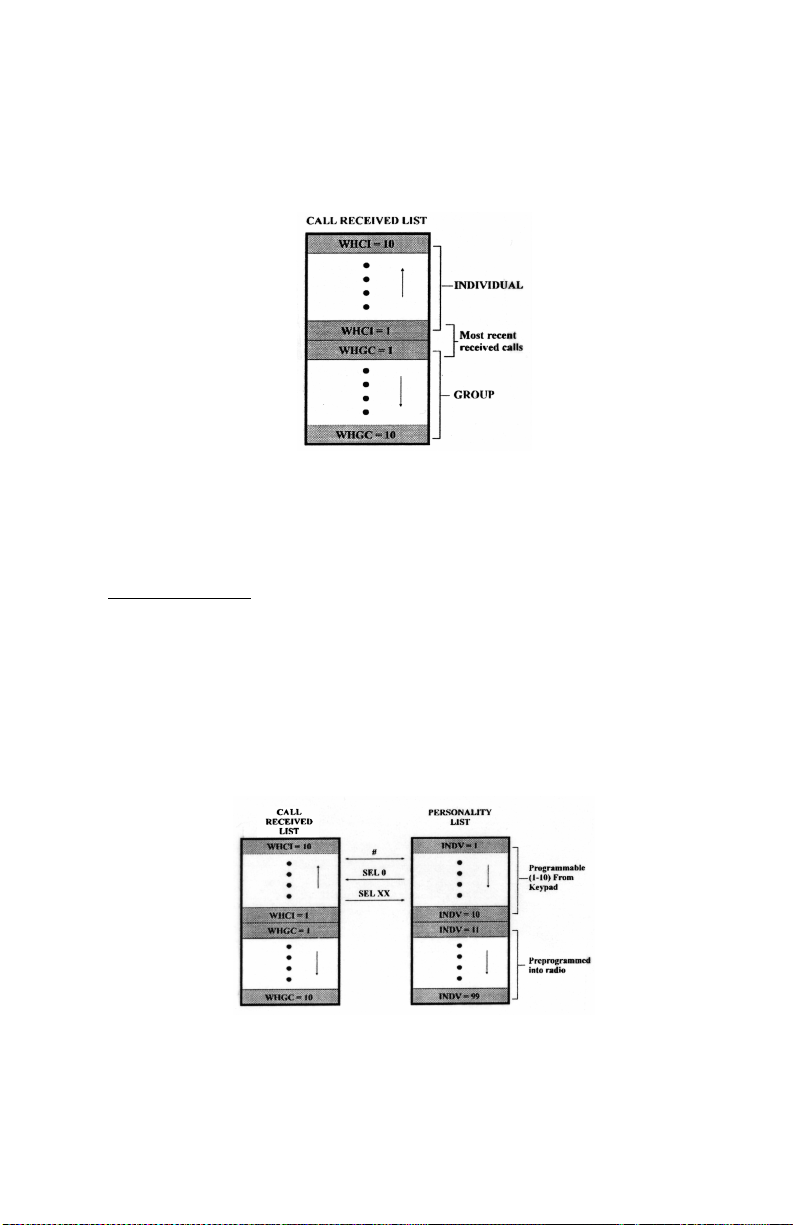
The radio stores the ID's of the last 10 callers in the Calls Received List as
shown. Individual calls are stored in the top half of the list (1-10) and group
calls are stored in the bottom half of the list (1-10). The most recent call is
stored in position 1, the second most recent call is stored in position 2, etc.
To access the list, press the i key twice. Use the , or . keys to
scroll through the list. Pressing the
key will display the time elapsed
m
since the call was received.
Call Storage Lists
There are two lists available for call storage in the radio, the calls received
list (1-10) and the personality list (1-99 as defined by the user). When the
individual call mode is entered by pressing
, the calls received list is
i
available. The user can toggle to the personality list by selecting any key
other than
(0) or toggle between the two lists by pressing the
d
i
key. If wrap is enabled, the calls received list wraps on itself and not into
the other list.
The saved call list shows all ten storage locations. if no calls have been
received, the saved call list will be empty and the pre-stored list will be
available upon entering the individual call mode.
43
Page 44

When in the saved call list, pressing
toggles the time stamp on and
m
OFF. The time stamp indicates how long ago the call was received. The
display indicates this information as HH:MM:SS where HH = hours, MM =
minutes and SS = seconds.
When in the pre-stored list, pressing
toggles the Logical IDentification
m
(LID) on and OFF.
Sending An Individual Call
The following procedures describe how to initiate and complete an
individual call.
1. T o select a previously stored individual, select the I-Call mode from the
menu or press
followed by the RAMP control , or . to scroll
i
through the list of stored individuals. The selection mode rules apply.
While in the individual call list, the menu key will toggle the display
between the call name and the unit ID number. If the individual is not
stored in this list but the individual's unit ID is kno wn, it can be entered
directly from the keypad.
2. Press the PTT button; the radio performs the necessary signalling to
obtain a communication channel. When the signalling is complete and
the radio is clear to transmit, TX indicator turns ON and the channel
access tone sounds. Line one shows the called individual's name if
found in the list of stored individuals or ID followed by the logical ID
number of the unit being called. The message *INDV* disp lays on line
two. Proceed with the message.
SCAT OPERATION
A SCAT (Single Channel Autonomous Trunking) System operates with
same set of features as a standard EDACS system. The only significant user
change relates to the BSY indicator. Since only one channel, operating as
both control and working channel, exists in a SCAT System, the BSY
indicator will be ON when the SCAT channel is in the working channel
mode. When the transmission on the channel is completed, the indicator
turns OFF and indicates the return of SCAT control channel signalling.
44
Page 45

TELEPHONE INTERCONNECT CALLS
Receiving A Telephone Interconnect Call (Trunked Mode Only)
Receiving a telephone interconnect call is identical to receiving an
individual call. See the DTMF Overdial Operation section if access to
services requiring "over-dial" is needed. Overdial operations are available
for any special call whether it is an individual call or a telephone
interconnect call.
Sending A Telephone Interconnect Call (Trunked Mode Only)
Use the following procedures to initiate and complete a Telephone
Interconnect call:
1. To select a previously stored phone number, select phone call mode
from the menu, press
and use the RAMP control , or . to
p
scroll through the list of stored phone numbers. The selection mode
rules apply. While in the phone call list, the
key will toggle the
m
display between the phone call name and the phone call number. If the
phone number is not stored in this list but the phone number is known, it
can be entered directly from the keypad. If necessary, a pause can be
entered by pressing and holding 0-9, *, or # until an underscore appears
in the display.
2. Press and release the PTT button; the radio performs the necessary
signalling to obtain a communication channel. When the signalling is
complete and the radio is clear to transmit, TX indicator turns on and the
channel access tone sounds. Line one shows the accompanying name if
selected from the list of stored numbers or the phone number if entered
directly. The message *PHONE* displays on line two. The radio then
automatically transmits the programmed number stored in the special
call queue.
3. The telephone ringing will be heard. When someone answers the phone,
press the PTT button and speak into the microphone. Release the PTT
button to listen to the caller. Unsuccessful interconnect signalling
returns the radio to the normal receive mode and the number remains
displayed until the special call is cleared by pr essing the
c
button or
the time-out expires or another group or system is selected.
4. To terminate the call, momentarily press the
c
button.
45
Page 46

NOTE
The ORION radio is capable of simplex (one-way) conversation only.
The caller can only hear the radio if the PTT button is pressed (the radio
is transmitting) and the caller can only be heard when PTT is released
(the radio is receiving).
DTMF Overdial/Conventional Mode Telephone Interconnect
Once the radio has established a connection to the public te lephone syste m,
it may be necessary to "over-dial" more digits to access banking services,
answering machines, credit card calls or other types of systems that require
DTMF (Dual-Tone Multi-Frequency) access digits. Overdial operation can
also be used to initiate a telephone interconnect call via DTMF signalling if
a dial tone has already been accessed on the system. This is the method that
is used for making a telephone interconnect call while operating in the
conventional mode but will also function in trunked mode if a dial tone is
directly accessible. Telephone numbers and other number sequences for
overdialing can be stored in the phone list when programming the radio or
stored by the operator in the first ten phone list entries. These numbers are
accessed by pressing
then following the selection mode rules.
p
The following steps are required to dial these numbers:
1. Follow the procedure in Sending A Telephone Interconnect Call
(Trunked Mode Only) to establish a connection to the telephone
system or consult the system administrator for the procedure to access a
dial tone o n the trunked or conventi onal system.
2. Overdial numbers are transmitted using either method as follows:
METHOD 1:
Press and hold PTT while entering the overdial number
sequence from the keypad. This method sends DTMF tones
during individual, telephone interconnect, trunked group or
conventional channel calls. Anytime the PTT button is
pressed and held, the keypad is enabled for DTMF entry.
46
Page 47

METHOD 2:
Press
to enter the overdial select/entry mode and
p
follow the selection mode rules to call up a stored number
from the phone list or to directly enter the overdial digits.
Press PTT to send the overdial sequence once. If the
number needs to be transmitted again it must be selected or
entered again (this prevents unwanted numbers from being
sent the next time the PTT button is pressed during the
call).
This overdial select/entry mode remains active until the call
is dropped, cleared, or
is pressed. The overdial
m
select/entry mode can be re-entered if the call is still active
by pressing
p
.
Programmable Entries
Individual call ID numbers, telephone numbers and other number sequences
for overdialing are stored in the special call lists when programming the
radio. The first ten entry locations of these lists can be changed by the radio
operator. The keypad is used when adding, changing and storing numbers in
these entry locations.
Use the following procedure to store a number in one of the first ten entries
of a special call list:
1. Press
or p to enter the individual call list or the phone call li st.
i
The selection mode rules apply.
2. Scroll through the list using the RAMP control , or . until one of
the first ten entries is reached. NO ENTRY is displayed if the location
is empty.
3. Enter the desired number. If necessary, a pause can be entered by
pressing and holding 0-9, (*), or (#) until an underscore appears in the
display. The individual call list entries will accept up to 5 digits. The
phone call list entries accept a combination of up to 31 digits and
pauses.
4. Press and hold
until the display changes indicating that the number
m
has been stored.
5. Repeat the steps above if the number stored in an entry location needs to
be changed.
47
Page 48

MOBILE DATA
The ORION radios when operating in the EDACS configuration permit
either voice or data calls to be transmitted or received. The radio can handle
only one type of call at a time; however, selection of either data or voice is
selected transparently by the operator through normal usage of the radio.
Data communications is not supported in the conventional mode.
The mobile radios may be connected to Mobile Data Terminals (MDT) or
to a host computer. Any RS-232 compatible device that supports the Radio
Data Interface (RDI) protocol (Version 1.91 or greater) may be connected to
the mobile radio. Support for MDT's or host computers is a programmable
option per radio. Additionally, radios programmed for host computers may
also be programmed for data only operation (no voice calls transmitted or
received).
NOTE
Turn the power of the radio OFF before connecting or disconnecting any
cables, including the data cable. Also, turn the power of the radio OFF
when docking or undocking a connected laptop computer. Failure to
turn the power of the radio OFF may damage the radio, requiring the
replacement of an internal non-user servicable fuse.
Displays
The following will be displayed on the control unit during the various states
of data mode of operation.
TX DATA
RX DATA
DATA OFF
DATA ON
48
Displayed on bottom line of display when the radio is
transmitting a data call.
Displayed on bottom line of display when the radio is
receiving a data call.
Displayed on top line of display when the radio is in the
data disabled state.
Displayed for two seconds on top line of display when the
radio is toggled to the data enabled state.
Page 49

Data OFF Operation
The radio can be placed in the data disable state by any of the following
methods. When the data state is disabled, the control unit displays "DATA
OFF" on the top line. An ongoing data call is allowed to complete except in
the case of declaring an emergency.
Removing the microphone from the hookswitch (hookswitch option
•
must be enabled by pre-programming).
Declaring an emergency (not to be used unless an actual emergency
•
condition exists). Alert tone will sound.
Pressing the o button (System Model) or
•
(pre-programmed). Alert tone will sound.
Selecting the function usi ng the m button (pre-programmed).
•
Pressing the ND button (System Model Only) (pre-programmed).
•
Data On Operation
The data state is enabled by one of the following (depending on how it was
disabled). "DATA ON" will be displayed top line of display for 2 seconds
then the display returns to normal.
Replacing the microphone into the hookswitch (going on-hook). Only
•
valid if the data OFF operation was entered by removing the
microphone from the hookswitch (going OFF-hook).
Pressing the ND key toggles data state on or OFF.
•
Clearing an emer gency but valid only if emerge ncy cau sed data OFF
•
operation.
O
(Scan Model)
49
Page 50

Exiting Data Calls
Under normal conditions, the radio enters the scan lockout mode and
returns to the control channel after completion of a data call (transmit or
receive). If, during a data call, one of the following conditions occurs, the
data call is immediately terminated and the radio performs the desired
function:
PTT activated.
•
PTT in Public Address mode.
•
Emergency declared by pressing the pre-programmed emergency
•
button.
A group or system change.
•
Scan Lockout Mode
Following the transmission or reception of a data call, if scan is enabled,
scanning will stop temporarily (duration pre-programmed). During this time
the scan LED will flash to indicate that scan is enabled but temporarily
suspended. This mode is normally exited when the pre-programmed time
expires; however, the following actions will terminate the scan lockout
mode before the timeout is completed.
The
•
PTT is pressed.
•
A group or system change.
•
Entering phone call mode
•
Entering individual call mode.
•
A new emergency assignment has been received.
•
PTT pressed in Public Address Mode.
•
An emergency declared or cleared.
•
Microphone removed from hookswitch (OFF-hook).
•
Receiving an individual or phone call.
•
Receiving Agency, Fleet or System All Call.
•
Pressing the
•
50
(System Model) or
c
k
(Scan Model) button is pressed.
C
button to turn scan ON or OFF.
Page 51

Data Lockout Mode
The data lock mode is a pre-programmed mode when the radio will not
respond to any data channel assignments and prevents receive data calls
from interrupting voice calls. Transmit data calls will still be initiated when
needed by the operator. After a pre-programmed time, the radio will
respond to receive data calls; however, the follo wing conditions will clear
the data lockout mode:
The c (System Model) or
•
Transmitting a data call.
•
Changing a system.
•
An emergency.
•
Pressing PTT while in Public Address mode.
•
Turning scan ON with the SCAN button.
•
(Scan Model) button is pressed.
C
STATUS/MESSAGE OPERATION
Status and message operation is possible with either the Scan or System
version of the ORION radio unit. The following procedure is applicable for
the System version. For operation with the Scan vers ion the four primary
keycaps must be reconfigured and pre-programmed for status/message
operation.
51
Page 52

Status Operation
Status operation permits the transmission of a pre-programmed status
condition to the EDACS site.
To send a status condition, press t he
button (keylight comes on) then
s
press one of the number buttons (0-9) to select the pre-programmed status.
If no status has been programmed for the selected number button, the radio
will display NO ENTRY and the radio will sound a low tone. A valid
selection will permit the status text to appear in the display for a pre-
programmed time. After the time-out expires or the
pressed (the
button will override the time-out period), the status is
m
button has been
m
selected and will be transmitted to the site or stored in the radio memory
where it can be polled by the site at a future time. If the site receives the
status properly, when transmitted or polled by the site, a high pitched tone
sounds and the keylight associated with that status will remain lit. If the site
does not receive the status properly, a low pitched tone sounds and the
keylight associated with the status will blink.
If an incorrect status was selected or the incorrect number button was
pressed, the status can be changed during the pre-programmed time-out
period by pressing another number button. The status selection can also be
cancelled by pressing the
button prior to the time-out period.
c
To view the currently selected status after it has been transmitted, press the
button. If the status was not sent successfully to the site, the text
s
associated with the status will flash in the display.
The radio can also be pre-programmed to redesignate the keypad buttons for
ST0 thru ST9 to send status condition. In this configuration the radio status
operation will operate as previously described except the
button is not
s
required. The keylight associated with ST0 thru ST9 will indicate which
status is selected.
52
Page 53

Message Operation
Message operation permits the transmission of a pre-programmed message
text to an EDACS site.
To send a message, press the
button (keylight comes on) then press one
n
of the number buttons (0-9) to select the pre-programmed message text. If
no message text has been programmed for the selected number button, the
radio will display NO ENTRY and a low pitched tone sounds. A valid
selection will permit the message text to appear in the display for a pre-
programmed time. After the time-out expires or the
pressed (the
button will override the time-out period), the message
m
button has been
m
textis selected and will be transmitted to the site. If the site receives the
message properly when transmitted, a high pitched tone sounds and the
n
keylight remains lit. If the site does not receive the me ssage p roperly, a low
pitched tone sounds and the
keylight will blink.
n
If an incorrect message text was selected or the incorrect number button was
pressed, the message text can be changed during the pre-programmed timeout period by pressing another number button. The message text selection
can also be cancelled by pressing the
button prior to the time-out
c
period.
To view the currently selected message text after it has bee n transmitted,
press the
button and then the c button prior to the time-out period. If
n
the message text was not sent successfully to the site, the text associated
with the message will flash in the display.
EDACS CONVENTIONAL P1 SCAN
This feature permits the radio user to scan a pre-programmed conventional
system and channel as a Priority 1 (P1) channel while the radio is selected
for EDACS trunked system. If activity is detected on the conventional P1
channel, the radio will unmute and remain on this conventional channel for
the programmable hang time.
The radio must be pre-programmed to designate a button for scan ON/OFF
operation.
53
Page 54

DYNAMIC REGROUP OPERATION
Dynamic regroup operation permits multiple talk groups (up to eight) to be
added to a radio via the system manager. The radio must be preprogrammed to respond to regrouping. Dynamic regrouping will not be
activated in a radio until an activation message is sent by the system
manager. Each radio that receives and acknowledges a regrouping
instructions is successfully regrouped.
Pressing and holding the
button for 2.5 seconds toggles the user into and out of the dynamic regroup
groupset. A double beep will sound for entry or exit. The display will
indicate REGR_0x where "x" is a digit of 1 to 8 indicating the group when
dynamic regroup has been enabled by the user. If the radio is in dynamic
regroup and the user selects a group that has not been regrouped, the display
will sh ow NO ENTRY. The radio will be prevented from transmitting and
receiving calls in this condition except for scanned groups.
Emergency Operation
If the pre-programmed groupset on the currently selected system contains
an EMER/HOME group and the radio is in dynamic regroup, the radio will
exit dynamic regroup and declare the emergency on the HOME group. If no
EMER/HOME group is present, the radio will declare the emergency on the
currently selected dynamic regroup group.
(Scan Model) or c (System Model)
C
CONVENTIONAL MODE OPERATION
The radio functions in the conventional mode when using conventional
communications channels (non-trunked). Each channel consists of a preset
frequency pair for transmit and receive during repeater operation, or a single
frequency for both transmit and receive during talk-around (no repeater)
operation. To use this mode, the operator selects a conventional system
which includes one or more conventional channels. Each conventional
channel may have one or more features, such as Channel Guard,
programmed when the channel is selected.
The
be monitored. When pressed and held for approximately 3 seconds this
button toggles conventional channel decoding (Channel Guard, Digital
Channel Guard or T99) on and OFF, if programmed for the selected
channel.
54
button unmutes the receiver so activity on the selected channel can
c
Page 55

RECEIVING A CALL
1. Turn ON the radio by rotating the POWER ON-OFF/VOLUME knob
clockwise (out of detente). A short alert signal (if enabled through
programming) indicates the radio is ready to use.
2. Adjust the POWER ON-OFF/VOLUME knob to the desired volume
level.
3. Select the desired conventional system and channel. The display
indicates the current conventional system and channel names.
4. The radio is now ready to receive calls.
5. When the radio receives a call (and the correct encoding is decoded, if
programmed and enabled), it unmutes on the channel and the BSY
indicator comes on.
SENDING A CALL
1. Turn ON the radio and set the POWER ON-OFF/VOLUME knob to
the desired volume level. Select the desired conventional system and
channel.
2. Ensure that the channel is not busy by pressing the
momentarily disable any channel decoding and unmute the receiver or
observe the unlit BSY indicator. If the Channel Busy Lockout feature is
programmed for the selected channel, the radio will not transmit when
the channel is busy.
3. Press and hold the PTT button. The TX indicator will turn on and a
short beep sounds (if programmed) indicating that communication can
begin.
4. Hold the microphone approximately three inches from the mouth and
speak in a normal voice.
5. Release the PTT button when the transmission is complete and listen for
a reply.
c
button to
EMERGENCY OPERATION
If enabled, G-STAR emergency signalling can be transmitted when
operating in the conventional mode. This G-STAR sig nalling will transmit 5
times with a delay between each transmission. To send an emergency call
on the selected conventional system and channel (or on an optionally pre-
55
Page 56

programmed conventional emergency system and channel), proceed as
follows:
Press and hold the red
button for approximately one second (this time
E
is programmable and, therefore, could be longer or shorter; check with the
system administrator). The radio turns on the TX indicator and proceeds to
transmit the pre-programmed G-STAR emergency signalling sequence.
G-STAR is programmed to transmit in one of the following methods:
METHOD 1:
G-STAR is transmitted on the selected channel. If the
channel is changed the emergency signalling will continue
to be transmitted on the newly selected channel.
METHOD 2:
Same as METHOD 1 but the radio will lock on to the
currently selected channel. Any attempts to change the
system or channel will be disabled.
METHOD 3:
G-STAR is transmitted on a pre-programmed conventional
emergency system and channel regardless of the selected
channel. In this case the selected channel is available for
voice transmission and the radio will periodically change to
the pre-programmed emergency system and channel to send
the emergency signalling and then change back to the
selected channel.
METHOD 4:
Same as METHOD 3 but the radio will lock on to t he preprogrammed emergency system and channel. Any attempts
to change the system or channel will be disabled.
The emergency state can be cleared by turning the radio OFF and then back
ON.
Using 5-Tone Signalling for Emergency Declaratio n
If 5-Tone signalling is defined for emergency declaration in place of GSTAR emergency signalling, a pre-programmed tone sequence will be
transmitted instead of the G-STAR sequence. This emergency declaration
functions as the G-STAR emergency in al l other respec ts.
Tone Encode Transmission
In conventio nal mod e two ke ys can be defined to b e to ne enc od e tri gger s. I f
either one of the pre-programmed tone encode triggers is pressed, a preprogrammed tone sequence will be transmitted on the current system and
channel. (See Emergency Operation if
key is used.) The TX
E
indicator will light during tone transmission and a beep will sound at the
56
Page 57

end of the transmission. If enabled, audible side tones will be heard in the
radio speaker as well. If PTT is pre-programmed as one of the triggers, the
microphone will become active for voice communication after the tone
sequence is complete.
Tone encode will be transmitted with Channel Guard if one is defined, and
tones are always transmitted in clear voice mode, even if the channel is set
for digital or private (see VOICE MODES). Digital or private voice
transmission will resume normally after the tone transmission.
SCANNING CONVENTIONAL CHANNELS
Channels which have been previously added to the scan list on a per system
basis may be scanned. The selected channel is scanned (if enabled through
programming) whether or not it is in the scan list. Each conventional
system's channel scan list is retained in memory when the radio is turned
OFF.
The scan rate will vary depending upon the number of channels in the scan
list and whether or not the radio is programmed to scan for channels with
decoding enabled. Fewer channels will result in a faster scan rate. If
programmed for dual-priority scan operation, the priority-one, priority-two
and the remaining scan list channels are scanned. Once a signal is detected
and the correct encoded squelch signal is decoded (if programmed), the
radio receives the message and displays the received scan channel. At the
same time, scanning continues on the priority-one and priority-two
channels. Should the priority-one or priority-two channel carrier, regardless
of encoded squelch decoding, be detected while a non-priority channel is
being received, the display name is updated and the received channel is
switched to the priority channel. Scanning of the priority-one chan nel will
continue if a message is being received on the priority-two channel.
While receiving a call on a non-priority or a priority two channel, the radio
periodically checks the priority one and two channels. If Scan with Channel
Guard is enabled, the radio will use Channel Guard to decide whether to
unmute on a priority channel. The radio will stop, on squelch detection, on a
priority channel. In normal operation, the radio will unmute only on
detecting the correct Channel Guard; otherwise, it will remain muted until
the priority channel call and hang time have ended. An optional feature
allows the radio to continue scanning upon the detection of the wrong
Channel Guard on a priority channel. The user can then select the rate this
channel is scanned until the call there ends.
57
Page 58

Adding Channels To A Scan List
1. With scan operation turned OFF select the desired channel to add to the
selected conventional system channel scan list.
2. Press < or > on the SCAN add/delete control. The current status
will be displayed in column 1 of line one for a time-out period. Press
to add the channel to the scan li st. S is displayed on the line. This
<
sets the selected channel for non-priority scanning. A second press of
< sets the channel for priority-two scanning and 2 is displayed on line
one. An additional press of < sets the channel for priority-one
scanning and 1 is displayed on line one. If the priority-one or prioritytwo channels are already set and a new channel is then assigned as the
priority-one or priority-two channel, the previously assigned priority
channel will change to non-priority scanning. The priority setting
selection sequence is set and stops at priority-one therefore the channel
must be deleted from the scan list by pressing > before the channel is
set to a previous priority setting. Any channel that is in a system's
channel scan list will show S, 2 or 1 for the time-out period when it is
the selected channel.
Deleting Channels From A Scan List
1. With scan operation turned OFF select the desired channel to delete
from the selected conventional system's channel scan list.
2. Press < or > on the SCAN add/delete control. The current status is
displayed for a time-out period. Press > to delete the channel from the
scan list. S, 2 or 1 turns OFF. Any cha nnel that is not in a convent ional
system channel sca n list will show a "blank" for the time-out period
when it is the selected channel.
Nuisance Delete
A channel can also be deleted from the scan list, if it is not the currently
selected channel, by pressing > during scan operation while the radio is
displaying the unwanted channel. The channel will be deleted from the
conventional system's channel scan list in the same manner as if done using
the steps above. Deletions done in this manner will not remain deleted if t he
radio is turned OFF and then back ON.
58
Page 59

TURNING SCAN ON
1. Toggle scan operation ON by pressing
turn ON when the radio is scanning.
NOTE
Scanning will stop while microphone is OFF-hook if hookswitch feature
is enable t hrough programming.
2. When a channel on the scan list receives a channel assignment, the radio
unmutes on the assigned channel, BSY indicator comes ON and the
received scan channel is displayed.
The radio will continue scanning if a new channel is selected when
•
scan is ON.
Pressing the PTT button when scan is ON will cause the radio to
•
transmit on the displayed channel or to the currently selected channel
depending on programming.
Pressing < when scan is ON will cause the radio to recall the
•
scanned channel that was last received. This channel is recalled for a
period equal to the scan hang time.
. The SCAN indicator will
k
TURNING SCAN OFF
Toggle scan operation OFF by pressing
operation on the selected channel.
. The radio will resume
k
59
Page 60

SQUELCH ADJUST
In the conventional mode of operation, the squelch may be re-adjusted in
the MENU selection mode or from a front panel key on the keypad that has
been pre-programmed by the PC progamming software. A default value of
9 or any user level between 1 and 16 can be selected by the PC
programming software. The user can change this setting either of two ways
from the front panel keys.
NOTE
A value of 16 requires a strong signal to open squelch, a value of 2
requires a very weak signal to open squelch and a value of 1 is open
squelch.
NOTE
When squelch adjust feature is activated, Channel Guard, T99 decode
and Scan are disabled. When the squelch adjust feature is exited,
Channel Guard, T99 decode and Scan are restored to their previous
states.
Menu Selection
1. Press the m key and then use the RAMP control , or . to scroll
through the selections until SQUELCH is displayed. Then press
(SELECT) again.
m
2. The display will show SQLCH=xx, where "xx" is the value between 1
and 16.
3. Use the RAMP control , or . to scroll through the values. Then
press the
(SELECT) key to save the new value after the display
m
time-out (2 seconds). The displayed value will be selected and saved.
4. If the
or c key is pressed before the time-out, the menu feature
m
will exit and the squelch level will not be updated. The original value
will be restored.
Pre-Programmed Keypad Key
1. Press the pre-programmed key and the display will indicate
SQLCH=xx, where "xx" is the value between 1 and 16.
60
Page 61

2. Use the RAMP control , or . to scroll through the values. Then
press the
(SELECT) key to save the new value or wait for the
m
display time-out (2 seconds). The displayed value will be selected and
saved.
3. If the
key is pressed before the time-out, the squelch level will not
c
be updated and the original value will be restored.
NOISE BLANKER OPERATION
A noise blanker feature is available in the low band (29-50 MHz) version of
the Orion radio which provides ignition noise filtering. The feature can be
enabled through either the pre-programmed menu selection or a preprogrammed key on the control unit. The noise blanker state is remembered
through a power cycle and its state will be displayed at power-up (i.e., NB
ON or NB OFF). The menu selection or the pre-programmed key will
toggle the state of the noise blanker and display the new state.
Menu Selection
Press m and then use the RAMP control , or . to scroll through the
selections until NB ON or NB OFF is displayed. Then press
toggle the noise blanker state (NB ON or NB OFF). After the display timeout (2 seconds) the n press
again to save the new noise blanker state
m
and return to normal operations.
Pre-Programmed Keypad Key
Press the pre-programmed key and the display will indicate NB ON or NB
OFF. Press the key again to toggle the function.
m
to
TYPE 99 DECODE (Conventional Only)
If the Type 99 Decode Option has been pre-programmed, individual
selective calling is possible. The radio can now decode individual, group or
supergroup paging calls. Two sets of Type 99 paging codes must be preprogrammed into the radio. When the radio decodes an appropriate Type 99
code sequence, an alert tone and visual indicator is provided to the user. The
receiver then operates as a noise squelched unit until Type 99 is reset. Type
99 decode continues to operate during this noise squelched period. The
appropriate Type 99 alert tone will sound again if it detects a valid t wo-tone
sequence.
61
Page 62

Type 99 operation may be reset manually or automatically (preprogrammed). Manual reset is achieved by briefly pressing
c
, if
programmed. Automatic reset, if enabled, occurs after a 30 second interval
following the most recent decode of a Type 99 tone sequence. Hookswitch
(pre-programmed) may also enable or disable Type 99 decode. The preprogrammed key light will blink when Type 99 is disabled by the
hookswitch.
Type 99 decode will continue to be active while the radio's
c
button is
pressed. This allows the user to monitor calls and still be alerted when a call
is directed to the user. While the user continues to press
hear both calls and all Type 99 tone signals. If
is pressed for longer
c
, the user will
c
than two (2) seconds, Type 99 decode will either be disabled or re-enabled
depending upon its present state.
To check the Type 99 enable status, press the Scan Add/Delete
<
or >.
The current status of Type 99 decode will be displayed for a time-out
period. Type 99 is enabled when the letter T is displayed in the third
segment from right on the first line of the LCD display.
If a Horn Alert Option is installed and enabled with the Type 99 Decode
Option, the radio can beep the vehicle horn whan a Type 99 call is received.
This option permits alerting persons out of the vehicle when a call is
received.
NOTE
Type 99 is automatically disabled when Scan is enabled.
Menu Selection
Press
until T99 ENAB is displayed. Then press
and then use
M
.,
control to scroll through the selections
to toggle the Type 99
M
decode state. The T99 ON or T99 OFF display message is displayed for
two seconds to show the new state.
Pre-Programmed Keypad Key
Press the pre-programmed key and the T99 ON or T99 OFF display
message is displayed for two seconds to show the new state.
62
Page 63

DIRECT MODE OPERATION (Conventional System
Only)
The direct mode (or talk-around) provides short range, line of sight
communications. One of the buttons on the control unit must be preprogrammed for this feature to function.
1. Make sure the radio is ON and then select the desired conventional
system and channel.
2. Press the pre-programmed button to toggle the talk-around function ON.
3. Ensure that the channel is not busy by pressing the
Version) to mo mentarily disable any c hannel decodi ng and unmute the
receiver or observe the unlit BSY indicator. If the Channel Busy
Lockout feature is programmed for the selected channel, the radio will
not transmit when the channel is busy.
4. Press and hold the PTT button. The TX indicator will light and a short
beep sounds (if pre-programmed) indicating that communication can
begin.
5. Release the PTT button when the transmission is complete and listen for
a reply.
6. When the communications is completed, press the pre-programmed
button to toggle the talk-around function OFF.
c
or
C
(Scan
63
Page 64

TRUNKED OR CONVENTIONAL MODE
OPERATION
SIREN/LIGHT OPERATION
Each siren/light key is designed to control an optional siren/light p ackage.
Pressing a siren/ light key will light the key indicator . Each siren/light key
(except RESET) can be programmed for either CANCEL or ADDITIVE
operation. If programmed for CANCEL, then all other siren/light activity is
cancelled except for the activity associated with this key. If programmed for
ADDITIVE, then a key press will add its respective siren/light activity to
the current siren/light activity. It is important to note that while the lights
are additive, only a single siren can be active at a time. The current siren
will be determined from the recently pressed key that contains a siren
assignment.
Each siren/light key (except RESET) can be programmed for either Toggle,
Momentary o r T imed. In Toggle, each key press will toggle the state of the
key between ON a nd OFF. In Momentary, a key's respective feature will
only be active while the key is pressed and held. When programmed for
Timed, the siren/light key activity will only be active during the
programmable time-out window. The duration of the time-out window is
programmable between from .5-127.5 seconds. During the time-out window
the respective key indicator will be ON. When the timer expires, the activity
will be terminated and the indicator will turn OFF. If an additional time-out
key (programmed for ADDITIVE) is pressed during the time-out window,
then the time-out window is reset and both activities will terminate at the
same time.
Digital Voice (ProVoice / Aegis / Voice Guard Operation)
Voice Modes
Each system (trunked or conventional) in the radio is programmed for no
digital voice operation or one of the three supported Digital Voice formats
(ProVoice/Aegis, or Voice Guard). Aegis or ProVoice programmed systems
have three (3) different voice modes: clear (analog), digital and private.
Voice Guard systems have two (2) voice modes: clear (analog) and private.
The voice modes are programmed on a per-group basis within each trunked
system and on a per -cha n nel ba sis wit hi n ea c h co nve nt io na l s yste m. A rad io
must be equipped with the encrypt/decrypt option before it will op erate in
private mode.
NOTE
Current ProVoice Conventional operation is for talk-around mode only.
64
Page 65

TRANSMIT/RECEIVE MODE COMPATIBILITY
FOR AEGIS/PROVOICE OPERATION
GROUP/CHANNEL
PROGRAMMING
(TRANSMIT)
CLEAR Yes No No
DIGITAL Yes Yes No
PRIVATE Yes No Yes*
TRANSMIT/RECEIVE MODE COMPATIBILITY
FOR VOICE GUARD OPERATION
GROUP/CHANNEL
PROGRAMMING
(TRANSMIT)
CLEAR Yes No
PRIVATE Yes Yes*
*assumes the proper cryptographic key is loaded
Conventional Aegis or encrypted channels require Channel Guard on the
channel to operate correctly.
Clear Modes
Aegis clear, ProVoice clear and Voice Guard clear modes are identical
voice modes in which the radio transmits and receives only clear (analog)
voice signals. These analog signals are non-digitized and non-encrypted.
Clear mode transmissions can be easily monitored by unauthorized persons.
Groups or channels programmed for clear operation cannot transmit or
receive unencrypted digital or private messages.
CLEAR
RECEIVE
CLEAR
RECEIVE
NOTE
DIGITAL
RECEIVE
PRIVATE
RECEIVE
PRIVATE
RECEIVE
AEGIS/ProVoice Digital Mode
Aegis/ProVoice digital mode allows the radio to transmit and receive
digitized voice signals. These digital signals provide improved weak signal
performance and they cannot be easily monitored with a standard receiver.
Groups and channels programmed for Aegis or ProVoice digital operation
transmit only digital signals. Private calls cannot be received or transmitted
when the radio is in the Aegis or ProVoice digital mode because the radio
does not know the cryptographic key used.
65
Page 66

Message trunked group calls and individual calls will be answered back in
the mode they were received, assuming the call or hang time is still active.
Individual, phone, all and emergency calls will be transmitted clear if digital
mode is disabled or inoperative.
1. If receiving an analog message trunked call, the radio will respond in
analog mode during the hang time on the working channel.
2. If receiving an analog I-Call, the radio will respond in analog mode
during the hang time.
3. When using the "WHC" feature to respond to an I-Call (after the hang
time has expired), the call will be transmitted in the mode defined by the
system mode as programmed for the current system if the ID being
called is not in the I-Call list. If the ID is in the I-Call list, then the call
will be transmitted as defined by the I-Call mode programmed in the list
for that ID.
DTMF
The overdial and hot keypad features for transmitting DTMF tones are not
available while in the Aegis Digital Mode or ProVoice Digital Mode.
ERROR Messages
If any of the following error messages are displayed, the radio was either
programmed incorrectly or needs servicing:
DSP ERR
ERR=xxxx
Power Up Only
If the Aegis or ProVoice circuit board is not responding, correctly, one of
the following error messages will be displayed and the radio needs
servicing:
3X will be a number between 30 and 38
66
DSP ERR DIGV ERR
HARDWARE
ERR= 3X
Page 67

AEGIS Private, ProVoice Private, And Voice Guard Private Modes
The Aegis, ProVoice and Voice Guard private modes allow the radio to
transmit encrypted messages and receive clear or private transmissions. The
radio will transmit private if the group/channel is programmed for private
operation and forced operation is pre-programmed.
If the radio was pre-programmed for autoselect, the radio will transmit in
the following modes;
Private mode enabled, transmission always in private mode.
•
Private mode disabled and private call received. Reply transmission
•
will be private mode if made during scan hangtime. If reply
transmission occurs after scan hangtime, transmission will be in clear
mode.
Aegis or ProVoice transmissions cannot be received by a radio set to
receive a Voice Guard transmission. Accordingly, Voice Guard or ProVoice
transmissions cannot be received by a radio set to receive an Aegis
transmission and niether Aegis or Voice Guard transmissions can be
received by a radio set to receive ProVoice.
Cryptographic keys are transferred to the radio using a cryptographic
Keyloader. Up to seven (7) different cryptographic keys, numbered 1-7, can
be transferred from a Keyloader and stored in the radio. An individual key
is automatically selected on a per-group/channel basis according to the
radio's programming. Groups and channels within Aegis, ProVoice, or
Voice Guard systems can be programmed for keys 1-7. Up to 8 banks of 7
keys can be stored for Aegis (DES and VGE) systems.
DES radios require a DES Keyloader (Option V4025 with software version
3.n or later). VGE radios require a VGE Keyloader (Option V4028 with
software version 2.n or later).
When operating on a group or channel programmed for private mode, all
transmissions will be private transmissions and the radio will receive clear
and private signals. T he P VT ke yli ght ( S ys tem Model) o r OP T I ON ke yli ght
(Scan Model) turns ON when the private mode is enabled. If the selected
group or channel is programmed for autoselect capability, t he mode may be
toggled between private and clear with the PVT button (System Model) or
button (Scan Model). Radios programmed for forced private operation do
not allow a change of the transmit mode; therefore, the PVT button (System
Model) or
button (Scan Model) has no effect.
O
67
O
Page 68

Transferring Keys Into The Radio
The following procedure outlines basic key transferring steps.
1. Turn the radio OFF.
2. Ensure that the PC programming cables and adapter box are
disconnected from radio unit.
3. Plug the modular connector of the Keyloader cable into the Keyloader
modular jack.
4. Connect the Keyloader cable to the keyloader level converter and then
to the extended options cable DB25 on the rear of the radio.
5. Press the PWR button on the Keyloader and wait for the Keyloader to
display "MASTER MODE".
6. Press the TRN button on the Keyloader. If necessary, select a different
cryptographic key to be transferred into the radio.
7. Turn the radio ON. Use the
button to access the menu options then
m
the RAMP , , . control to select KEYLOAD.
8. Press
(SELECT). Then use the RAMP control , or . to select
m
the bank location.
9. Press the EXE button on the Keyloader to transfer the key. The
Keyloader will display "GOOD 1.x TRANSFER" where "x" is the
selected cryptographic key number.
10. Disconnect the cable from the extended option cable. Press the
C
(Scan Model) or c (System Model) button to exit the keyload
operation. The radio will change to the selected group or channel as
indicated in the display.
Displaying The Currently Used Cryptographic Key Number
To display the cryptographic key currently in use for either the system
encryption key (for special call such as individual, phone, all, agency or
fleet) or the group/channel key (for group or conventional calls), perform
the following procedure:
1. Press the
m
button.
2. Use the , or . button (ramp control) to select DISP KEY. Then
press the
(SEL) button.
m
3. Then use the , . button to toggle between displaying the system
key or the group/channel key.
68
Page 69

ENCRYPTION KEY
MESSAGE DISPLAYED
DISPLAYED
System "SYS KEY"
"KEY = 1"
Group/Channel "GRP KEY"/"CHN KEY"
"KEY = 2"/KEY = 2"
Key Zero
All cryptographic keys can be zeroed (erased from radio memory) by
pressing the
still pressing this button, press and hold the
(Scan Model). Press both buttons for 2 seconds. A series of warning beeps
O
button (System Model) or
c
(Scan Model) and while
C
button (System Model) or
o
will begin at the start of this 2 second period and then switch to a solid tone
after the keys have been zeroed. The display will indicate KEY ZERO.
If the cryptographic key(s) are zeroed, one or more keys must be transferred
from the Keyloader into the radio before private communications may
continue.
Private Operation
Receiving An Encrypted Call
When receiving, the radio automatically switches between clear or private
operation. If the transmission being received is an encrypted transmission, it
will be decrypted, the PVT keylight (System Model) or OPTION keylight
(Scan Model) will flash, the receiver will unsquelch and the message will be
heard in the speaker. For this to occur, the selected group or channel must
be programmed for private operation and the correct cryptographic key
must be loaded into the radio.
Transmitting An Encrypted Call
1. Select the desired group or channel.
2. Place the radio in private mode by pressing the PVT button (System
Model) or
(Scan Model). When private mode is enabled, the PVT
O
keylight (System Model) or OPTION keylight (Scan Model) will be
ON.
69
Page 70

If the last state of the radio was private mode, the priva te mode will be
enabled on power up. Also the private mode will be enabled if forced
operation has been programmed in the radio
If a group or channel is not programmed for private mode operation,
PVT DIS will be displayed if an attempt is made to enable private
transmit mode. It is not possible to operate on this group/channel in
private mode.
If the radio is programmed for forced private transmit operation, FRCD
PVT will be displayed if an attempt is made to disable private transmit
mode. It is not possible to transmit on this group/channel in clear mode.
If the radio does not have the correct encryption key loaded, NO KEY #
will be displayed and the call will not be transmitted.
3. Continue with standard transmission procedures. A private mode access
tone will be heard when the PTT button is pressed.
Scanned Group Calls
Receiving a scanned group call is the same as receiving a selected group
call. During the scan hang time, if the radio was programmed for autoselect,
it will transmit back in the same mode it received the call. For example, if a
clear group is entered in the scan list, it will only receive clear calls. If the
same group was available in private and entered in the scan list, it can
receive clear and private calls, provided autoselect was programmed in the
radio. The user can select transmitting on the scanned or selected group. If a
group is entered in the scan list more than once and in different modes
(clear, digital, private), only the first occurrence of the group will be used.
Conventional Operation
Outside Address
The same outside address (works similar to Cha nnel Guard operation) must
be programmed in the transmitting and receiving radios when Aegis or
ProVoice digital or private operation is enabled. If address is not correct,
the radios will not communicate.
70
Page 71

Channel Guard
Channel Guard encode is transmitted on analog clear channels only.
Channel Guard decode will operate on either a clear or private channel. The
exception is when G-STAR signalling is used (see G-STAR paragraph).
G-STAR
When G-STAR is programmed on a private channel, the radio will transmit
G-STAR in clear mode and then switch to private for the voice portion of
the call. If G-STAR is sent with Channel Guard, then both are sent in clear
mode and then radio switches to private mode. Emergency G-STAR data
burst is transmitted in clear mode.
DUAL CONTROL OPERATION
The ORION mobile radio may be programmed to operate from two separate
Control Units. This permits radio operation from two separate locations in
the vehicle. Dual control operation is available in both trunked and
conventional modes. Only one control unit can control the mobile radio unit
at a time. The control unit which controls the radio operation is called the
active controller and the second unit is called the idle controller.
Switching Control
Control can be switched to the idle controller by pressing the push-to-talk
(PTT) on the microphone associated with the idle controller. Once PTT is
pressed, the radio will switch control to the idle controller unless the active
controller is currently transmitting (i.e., PTT pressed on active controller),
in which case the switch will not occur. When control is switched to the idle
controller, two short high-pitched tones will sound at the controller where
PTT was pressed to indicate that the idle controller is now the active
controller and the previous active controller is now the idle controller.
Control Switching Modes
The radio can be pre-programmed for two modes of dual operation, Slaved
and Independent. In the Slaved mode the two controllers will use the same
radio System and Group settings. The Independent mode permits each
controller to have its own saved System and Group settings.
71
Page 72

Slaved Mode Operation
During Slaved mode operation either controller can operate the radio with
no change in System and Group settings when control is switched. Both
controllers display the current information. If a key is pressed at the idle
controller, other than PTT,
or siren and lig ht keys as note d i n fo ll o wi ng
E
paragraphs, a low tone will sound and the display will temporarily show
DUAL on line one of the idle controller.
When control is switched in a Slaved mode system, all of the radio settings
and states will remain in effect that have been selected on the active
controller.
Independent Mode Operatio n
During Independent operation, the radio system operates as if there are two
radio units each controlled by a separate control unit. Each control unit
maintains its own System and Group settings which are restored when
control is switched.
The idle controller will display DUAL on line one to indicate that it is idle.
If a key is pressed at the idle controller, other than PTT,
or siren and
E
light keys as noted in following paragraphs, a low tone will sound at t he idle
controller.
When control is switched in Independent mode, the idle controller will
restore its own System and Group settings instead of using the settings of
the previously active controller. Any pending operations at the active
controller, other than
or siren and light operations, will be terminated.
E
Emergency Operation
Either control unit (active or idle controller) can declare an emergency,
provided radio has been pre-programmed to enable emergency declaration.
If the idle controller declares an emergency, control is switched to the idle
controller and any current transmission from the previously active controller
is terminated.
Siren And Light Control
Siren and light control is only available from the control unit that is preprogrammed for these functions. Typically, the control unit at the driver's
location would be programmed. The control unit that has these functions
programmed can activate them regardless of whether it is an active or an
idle controller.
72
Page 73

Dual Control Audio
Audio output during dual control operation is a pre-programmed function.
Default operation routes audio only to the active controller.
MULTIPLE RADIO OPERATION
Orion mobile radio may be configured to operate in a multiple radio mode
that permits more than one radio to be controlled from a single control unit
or control location. The radios could be different frequency splits,
trunked/conventional, etc.
In the multiple radio operation, the radios continue to operate as individual
radios except with a common control unit. The control unit is used for
display and control. The control unit display is shared by the multiple radio
units and, when selected, a radio can be controlled by the control unit.
For multiple radio operation the control unit keypad must be preprogrammed for a variety of multiple radio buttons such as radio selection
and radio mute.
Changing Selected Radio
A radio unit may be selected by pressing the radio selection button (preprogrammed) on the control unit. Also, a button may be pre-programmed
to rotate selection through the radio units; e.g., if radio #1 is selected,
pressing the radio select button will select radio #2. Similarly, radio #2 will
be selected if the radio select button is pressed when radio #1 was selected.
Shared Control Unit Display Modes
Radios in the multiple radio operation share the control unit display. Preprogramming the radios determines what the control unit displays. There
are two modes of display: alternating radio display or first come first serve
display. See also the following paragraph on Audio Modes.
Alternating Radio Display
In this mode the control unit display will alternate between showing the call
information for the radios when more than one call is being received. This
mode is available only if audio is summed (see following paragraph on
Audio Modes).
73
Page 74

First Come First Serve Display
In this mode the control unit display will show the call information of the
radio that is providing the audio. A call in process prevents audio from
other radios from being heard for the duration of the call. This mode
corresponds with the first come first serve audio mode (see following
paragraph on Audio Modes).
Audio Modes
In multiple radio operation, the audio from the mobile radio units can be
pre-programmed to be summed or available on a first come first serve
process.
Audio Summed
When audio is summed, the audio from all radios will be available whenever the radios receive a call. If two radios receive a call simultaneously
both calls will be heard in the speaker.
Audio First Come First Serve
When audio is pre-programmed for first come first serve, the audio from the
radio that receives a call first will be heard from the speaker for the duration
of the call. During this time audio from the other mobile radios will be
muted.
Muting A Specified Radio
Pressing the control unit mute button associated with a particular radio will
mute its audio for a pre-programmed time period. The time period can be
cleared by pressing the control unit mute button or the radio selection
button.
Multiple Radio And Siren & Light Operation
For siren & lights to function correctly, both the master and slave radios
must be programmed with the same siren & light information.
Multiple Radio And Data Operation
Only the master radio supports mobile data operation.
74
Page 75

LAST SYSTEM/GROUP OR CHANNEL RECALL
(Supervisory Radio Units Only)
This feature enables the user to recall the last selected system/group after an
EDACS emerge ncy or home functi on, a conventiona l emergency o r home
function or system/group key function. This feature must be preprogrammed as "Enabled" to function. For example, if the Home button
(pre-programmed) is pressed, the radio will go to the designated Home
system/group or channel. If the Home button is pressed again, the radio
returns to the previous system/group or channel. At this time the user can
toggle between the Home system/group or channel and the previous
system/group or channel. The operation is the same for the SG1-SG5
buttons.
MACRO KEY OPERATION
Macro key operation permits the user to accomplish a series of key strokes
with a single "macro" key stroke. Up to ten (10) macro keys can be defined,
each capable of executing up to twenty (20) key strokes, to any pushbutton
input (i.e., keypad keys, buttons, etc.). Each macro key can be preprogrammed to activate when pressed or when released.
A macro key may also be pre-programmed to change the key stroke
sequence the next time the macro key is activated.
For detail operation and assignment of macro keys, contact your
communications supervisor or administrator.
75
Page 76

SENDING A MANUALLY ENTERED INTERCONNECT
CALL (SYSTEM MODEL ONLY)
1. Select a channel in the radio system that has telephone interconnect
capability. The radio should be programmed for DTMF operation on
this channel.
2. Press the
(secondary function).
3. Press and hold PTT to key the transmitter. While holdi ng the PTT , press
the * or # key (as required by the radio system to obtain a telephone
line). The radio will transmit the selected tone.
4. Release the PTT and listen for a dial tone. When the dial tone is heard,
press and hold the PTT while entering the desired telephone number. If
pre-programmed, as each digit is entered and transmitted, the DTMF
sidetone will be heard from the speaker.
5. After all the digits have been entered and transmitted, release the PTT.
6. When someone answers, press the PTT and speak directly into the
microphone. Release the PTT as soon as you stop talking to receive a
reply.
7. At the completion of the call, press and hold PTT and then press the * or
# key (as required by radio system) to terminate the interconnect call.
Release the PTT.
8. Press
k
interconnect calls are to be made.
button to toggle the keypad to the DTMF function
k
to toggle the keypad back to the primary function if no more
76
Page 77
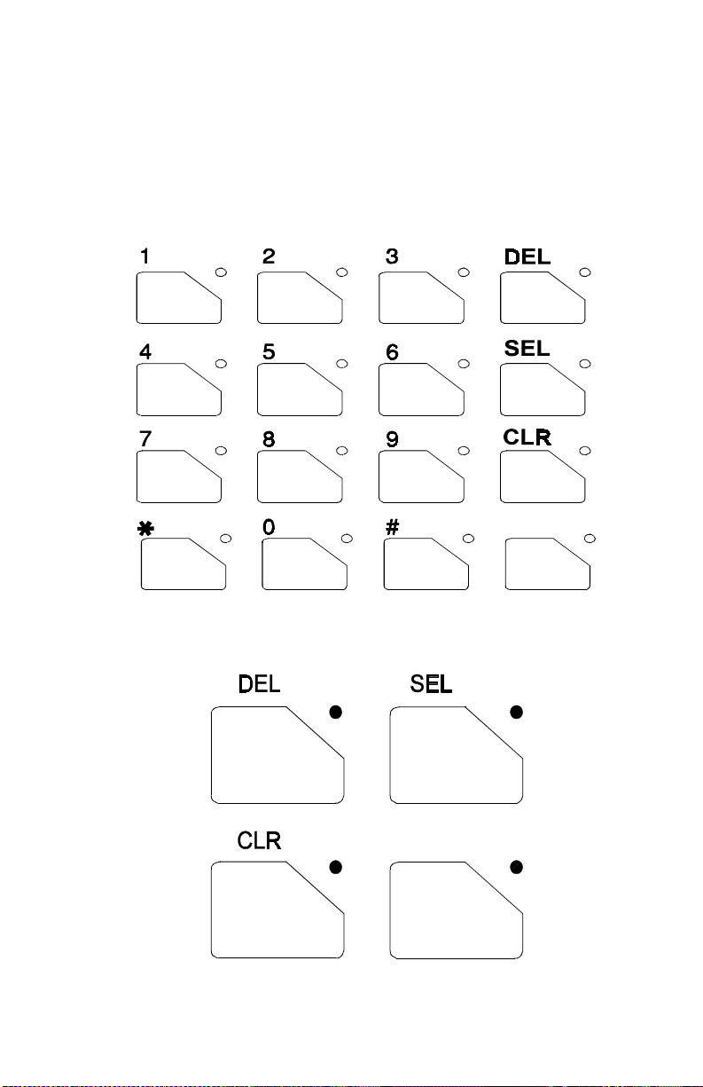
KEYPAD REMAPPING
If the keys ha ve been re mapped to provide new functio ns, please fi ll in the
following for fut u re reference.
ORION System Model Keypad
ORION Scan Model Keypad
77
Page 78

OPERATING RULES AND REGULATIONS
Two way FM radio systems must be operated in accordance with the rules
and regulations of the Federal Communications Commissio n (FCC). As an
operator of two way radio equipment, the user must be thoroughly familiar
with the rules that apply to the intended type of radio operatio n. Following
these rules will help to eliminate confusion, assure the most efficient use of
existing radio channels, and result in a smoothly functioning radio network.
When using the radio, remember these rules:
1. It is a violation of FCC rules to interrupt any distress or emergency
message. In conventional mode the radio operates in much the same way
as a telephone "party line" therefore always listen to make sure that the
line is clear--that no one else is on the air--before sending any messages.
If someone is sending an emergency message--such as reporting a fire or
asking for help in an accident- -KEEP OFF THE AIR!
2. Use of profane or obscene language is prohibited by Federal Law.
3. It is against the law to send false call letters or a false distress or
emergency me ssa ge.
4. The FCC requires that conversations be brief and confined to business.
To save time, use coded messages whenever possible.
5. Using the radio to send personal messages (except in an emergency) is a
violation of FCC rules. Only those messages e ssential for the business
operation may be sent.
6. It is against the Federa l law to repeat or otherwise ma ke known anything
overheard on the radio. Conversations between others sharing a
communications channel must be regarded as confidential.
7. The FCC also requires that the caller be identified at certain specific
times by means of call letters. Refer to the rules that apply to the
particular type of operation for the proper procedure.
8. No changes or adjustment shall be made to the equipment except by an
authorized or certified electronic technician.
78
Page 79

GLOSSARY
Agency
Base/Unit
Operation
Control
Channel
Conventional
Channel
Conventional
Mode
CCT
- An agency is composed of multiple fleets. Units can
be programmed to initiate agency calls to access
multiple fleets. (Trunked Mode Only)
- A programmed option used in some fleets so units
can only hear and talk to a base dispatch unit, not to
other mobiles or personals in the group. In this mode
of operation, when a unit in a particular group is
talking to the base dispatch unit, all other mobile
and personal radios in that group will receive a
"System Busy" tone if they try to access the system.
(Trunked Mode Only)
- a radio channel in a trunked system that is used to
digitally communicate with the radios operating on
the system when they are not engaged in active
voice communications.
- a radio channel (transmit/receive) that is allocated
for conventional (non-trunked) use and may be
manually selected by the operator.
- communicating on radio channels allocated for
conventional use (i.e. conventional system).
- Carrier Controlled Timer - a programmable timer
that will disable a transmission if the length is
exceeded.
CG
Fleet
- Channel Guard - a method of controlling speaker
mute with a tone or digital code.
- A fleet of users consists of multiple groups
(subfleets). Radios can be programmed to make fleet
calls to simultaneously access multiple user groups.
(Trunked Mode Only)
79
Page 80

Group Or
Subfleet
-
A group of users share the same program group
identification number in their mobile and personal
radios. All units in the same group will receive a
dispatch call placed by any one unit in the group.
(Trunked Mode only).
Group Scan
Individual
Call
Queueing
Site
Controller
- Programming that allows the radio to monitor many
groups simultaneously (multi-group decode),
permitting the user to both monitor and receive calls
from these groups. The radio may be programmed
with a scan hang time which causes the radio to
remain on the scanned group for a pre-programmed
amount of time, responding only to calls of a higher
priority such as priority scan group calls, individual
calls, fleet calls, agency calls, etc. When activity on
the scan group ends, and the pre-programmed time
has expired, the radio returns to monitoring multiple
groups. (Trunked Mod e Only)
- Every radio in the system is programmed with a
unique individual identification code. A mobile or
personal unit can be programmed to call another
particular unit by selecting the individual by name
or ID number . (Trunked Mode Only)
- The process that occurs when all channels in a
trunked system are busy and calls must be addressed
on a priority basis.
- The computer controlled radio equipment at the
repeater site that controls a trunking system.
System
(area)
System
Manager
System
Scan
80
- The terms "system" and "area" are used
interchangeably to refer to the particular group of
station repeaters currently providing service to the
radio.
- A computer that performs the data basing and
system monitoring for the site controller.
- A programmed feature to scan (monitor activity on)
separate trunked systems and receive calls on any of
these systems. (Trunked Mode Only).
Page 81

Talk-around
Mode
- Also referred to as "direct mode", talk-around
provides a direct unit-to-unit short range
communications link. It is intended to maintain
communications outside of the main system
coverage area.
Telephone
InterConnect
Trunked
Group
Trunked
Operation
Trunked
Radio
System
Trunked
System
T99
Wide Area
Encode
- This feature allows the user to initiate or receive
telephone calls through the radio if the system is
configure d for this operation. (Trunked Mode Only)
- A radio communications path shared by two or more
users.
- Trunked Op eratio n refer s to the use of a set of ra dio
frequency channels by multiple user groups. By
using high speed digital data the radio goes to an
unused channel when a call is initiated and will also
only respond to calls in the same user group. In this
way conversation privacy between user groups is
assured.
- A radio system in which a limited number of radio
channels is dynamically allocated to groups of
people for communication purposes.
- A set of one or more trunked groups.
- Type 99 - a method of opening mute for selective
page operations using sequential tones.
- A programmed option which ensures all system
scanning mobile and personal radios have time to
lock onto the call before the initiating unit is
allowed to talk.
Working
Channel
- A radio channel (transmit/receive) that is
automatically assigned by the site controller for
voice or data communications.
81
Page 82

OPERATOR'S RADIO SETUP
RADIO TYPE:
FREQUENCY BAND:
OPERATOR'S NAME:
EMERGENCY GROUP:
SYSTEM
NUMBER
SYSTEM
NAME
TRK/CNV GRP/CHN
NUMBER
GRP/CHN
NAME USE
82
Page 83

WARRANTY
A. M/A-COM Private Radio Systems, Inc. (hereinafter "Seller") warrants to the original purchaser for use
(hereinafter "Buyer") that Equipment manufactured by or for the Seller shall be free from defects in
material, workmanship and title, and shall conform to its published specifications. With respect to any
Equipment not manufactured by or for the Seller (except for integral parts of Seller's Equipment to
which the warranties set forth above shall apply), Seller gives no warranty, and only the warranty, if
any, given by the manufacturer shall apply. Batteries are excluded from this warranty but are
warranted under a separate Battery Warranty.
B. Seller’s obligations set forth in Paragraph C below shall apply only to failures to meet the above
warranties (except as to title) occurring within the following periods of time from date of sale to the
Buyer and are conditioned on Buyer’s giving written notice to Seller within thirty (30) days of such
occurrence:
1. for fuses and no n- r echargeable batt er ies, operable on arrival only.
2. for parts and accessories (except as noted in B.1) sold by Seller’s Service Parts Operation,
ninety (90) days.
3. for PANTHER™ Series handportable and mobile r adios, two (2) year s.
4. for Cougar™ S er ies handportabl e and mobile radios, t wo (2) years.
5. for all other Equipment of Sell er ’s manufacture, one (1) year.
C. If any Equipment fails to meet the foregoing warranties, Seller shall correct the failure at its option (i)
by repairing any defective or damaged part or parts thereof, (ii) by making available at Seller’s factory
any necessary repaired or replace men t pa rts , o r (iii) b y re placing the failed Eq uipment with equivalent
new or refurbished Equipment. Any repaired or replacement part furnished hereunder shall be
warranted for the remainder of the warranty period of the Equipment in which it is installed. Where
such failure canno t be co rrected by Se ller’s reasona ble e fforts , the pa rties will negotiate an equitable
adjustment in price. Labor to perform warranty service will be provided at no charge during the
warranty period only for the Equipment covered under Paragraph B.3. To be eligible for no-charge
labor, service must be performed by an Authorized Service Center (ASC) or other Servicer approved
for these purposes either at its place of business during normal business hours, for mobile or
personal equipment, or at the Buyer’s location, for fixed location equipment. Service on fixed location
equipment more than thirty (30) miles from the Service Center or other approved Servicer’s place of
business will include a charge for transportation.
D. Seller’s obligations under Paragraph C shall not apply to any Equipment, or part thereof, which (i) has
been modified or otherwise altered other than pursuant to Seller’s written instructions or written
approval or, (ii) is normally consumed in operation or, (iii) has a normal life inherently shorter than the
warranty periods specified in Paragraph B, or (iv) is not properly stored, installed, used, maintained or
repaired, or, (v) has been subjected to any other kind of misuse or detrimental exposure, or has been
involved in an accident.
E. The preceding paragraphs set forth the exclusive remedies for claims (except as to title) based upon
defects in or nonconformity of the Equipment, whether the claim is in contract, warranty, tort
(including negligence), strict liability or otherwise, and however instituted. Upon the expiration of the
warranty period, all such liability sha ll termin ate . The foregoin g wa rranties are exclusiv e and in lieu of
all other warranties, whether oral, written, expressed, implied or statutory. NO IMPLIED OR
STATUTORY WARRANTIES OF MERCHANTABILITY OR FIT NESS FOR PART ICULAR PURPOSE
SHALL APPLY. IN NO EVENT SHALL THE SELLER BE LIABLE FOR ANY INCIDENTAL,
CONSEQUENTIAL, SPECIAL, INDIRECT OR EXEMPLARY DAMAGES.
This warranty ap plies only within the United States.
M/A-COM
3315 Old Forest Road
Lynchburg, VA 24501
1-800-528-7711
AE/LZT 123 3248/1 R5A
83
Page 84

EMERGENCY NUMBERS
Police
State Police
Fire
Poison Control
Ambulance
Life Saving and Rescue Squad
OPERATING TIPS
The following conditions tend to reduce the effective range of two-way radios and
should be avoided whenever possible.
Operating the radio in low areas of terrain or while under power lines or bridges.
In areas where transmission or reception is poor, some improvements may be
obtained by insuring that the antenna is vertical (particularly if a glass mount antenna
is used). Moving a few yards in another direction or moving to a higher elevation
may also improve communications.
M/A-COM
3315 Old Forest Road
Lynchburg, Virginia 24501
(Outside USA, 434-385-2400)
Toll Free 800-528-7711 Printed in U.S.A.
 Loading...