

Page 1
35
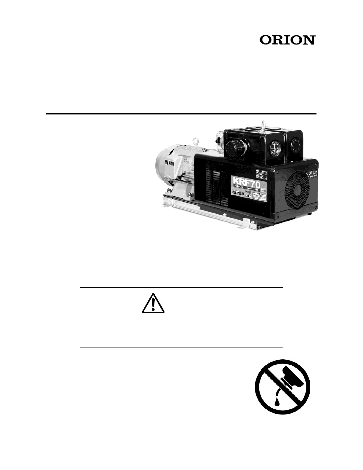
INSTRUCTION MANUAL
OILLESS ROTARY VACUUM PUMP & BLOWER
ORION DRY PUMP
CAUTION
●This product is intended only for industrial use. Use with caution.
●Read this Instruction Manual and follow the instructions described herein.
●Please keep this Instruction Manual for future reference.
No lubrication!
KRF70
KRF110
KRF70
Page 2
Thank you very much for your purchase of the Orion pump. Read this instruction manual in advance to
use this pump safely and to ensure continuing good performance. The product mechanism and
specifications are subject to change without notice. If mechanism or specifications are changed,
contents of this manual may not match the actual product.
Safety Information
Read "Precautions for Safety" before operation to ensure safe operation. Safety instructions in this
manual are intended to ensure safe and correct pump operation and to prevent damage or personal
injury. Safety instructions in this manual are classified into
Danger, Warning, and
Caution.
Danger
Indicates an imminently hazardous situation that, if the product is
misused, may bring about death or serious injury to the operator.
Warning
Indicates a potentially hazardous situation that, if the product is
misused, may bring about death or serious injury to the operator.
Caution
Indicates a critical situation that, if the product is misused, may bring
about injury to the operator or damage to the product.
Additionally, the situation that is explained in Caution column may cause serious accident. All
safety information must be followed for safe operation.
・
After reading this manual, keep it where an operator can refer to it anytime.
・
When transferring or renting this product, attach this manual to the product where a new owner can
easily refer to it for proper operation.
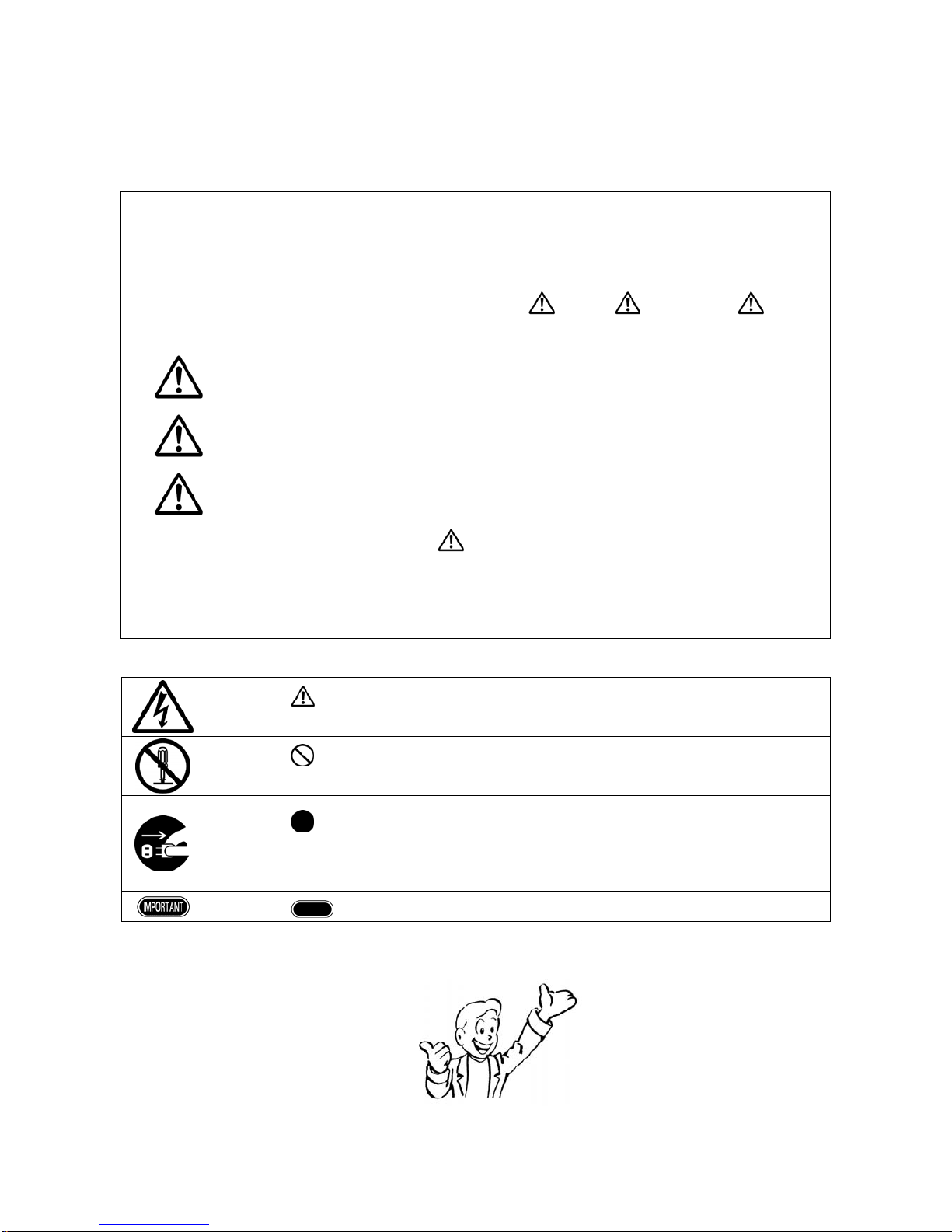
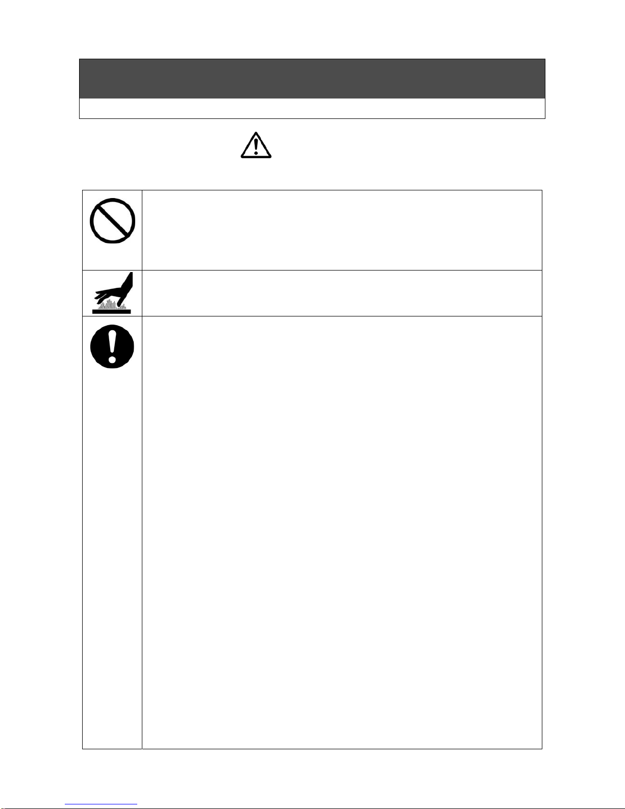
■Symbols
The symbol represents warning or caution. What is sho wn inside or des cribed near i nforms
of an actual hazard. The example on the left means caution for electric sh ock.
The symbol represents prohibition. What is shown inside or described near informs of an
actual action which is prohibited. The example on the left means prohibition of disassembly.
The symbol represents essential action or instruction. What is shown inside or described
near informs of an actual instruction about ope rati on. The ex am ple on the lef t m eans d iscon nect
the power plug from the outlet.
The symbol represents important information other than warning or caution.
Although model KRF70 is used as description pictures and figures in the manual, the oth er models in the
KRF-series are operated the same way as KRF70 if there is no note.
Be sure to read through the
safety information.
Page 3

1
Contents
Precautions for Safety ···················································· 2
Precautions for Proper Operation ····································· 6
Names of Components ··················································· 7
Preparation and Confirmation ·········································· 9
Operation Procedure ··················································· 13
Maintenance and Inspection ·········································· 16
Troubleshooting ·························································· 18
Consumable Parts ······················································· 20
Storage(Not in Use for a Long Time) ··························· 23
Disposal ···································································· 23
Specifications ····························································· 24
Dimensional Outline Drawing ········································· 26
Page 4
2
Precautions For Safety
Precautions for Use (Danger / Warning)
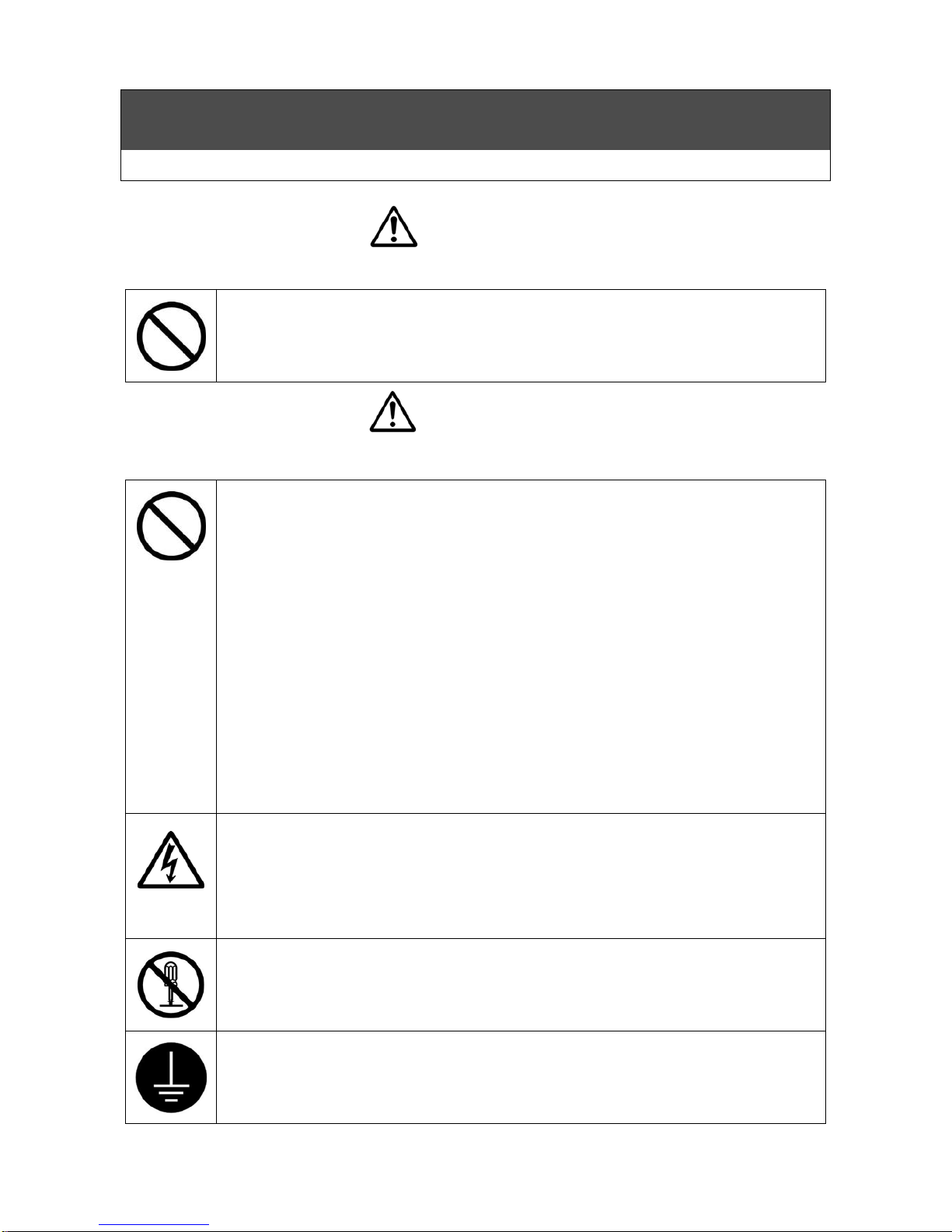
Danger
Indicates an imminently hazardous situation that, if the product is misused, may bring about death or
serious injury to the operator.
Keep flammable or explosive gas out.
Keep the pump from inhaling flammable or explosive gases. Do not use the unit in
the place where flammable or explosive gas exists. It may cause explosion or
fire.
Warning
Indicates a potentially hazardous situation that, if the product is misused, may bring about death or
serious injury to the operator.
Do not block the exhaust piping. (B type and V・B type)
Do not operate the pump while the pressure controller is totally closed or the exhaust
piping is blocked. Blocking the exhaust air may increase the pressure and
temperature in exhaust piping, and result in injury and malfunction due to burst
of the piping and pump parts.
Do not wash filter element with organic solvents.
When cleaning the filter element, do not use organic solvents such as thinner,
alcohol, benzine, gasoline, and kerosene. It may result in explosion or fire.
Do not remove the cover during operation.
Do not operate this product while the main cover is removed. Otherwise, your
hand(s) may be cut off or be seriously hurt because the cooling fan and the coupling
rotate at high speeds.
Prevent the power cord from any damage.
Do not damage, bend, pull, or bind the power cord. Do not place heavy object on it
or let it get caught or pinched. It may damage the cord, and may cause electric
shock or fire.
Keep this product away from water.
Do not pour water over the pump and the motor, and do not use water for cleaning
this product. Also, do not use this product where it may touch water or other liquid.
It may cause electric shock or fire.
Be alert to electric shock.
Do not touch electrical parts such as power plug with wet hands. Also, do not
operate switch with wet hands.
It may cause electric shock.
Never fail to put the terminal box cover on.
In the case of a motor with the terminal box, do not operate it with the terminal box
cover removed. It may cause electric shock.
Do not modify the product.
Do not modify the product.
It may cause abnormal operation and may result in injury, electric shock or
fire.
Be sure to ground this product.
Be sure to ground the product with the screw for grounding inside the terminal box or
at the lower part of the frame of the motor.
Failure to do so may cause electric shock.
Page 5
3
Precautions For Safety
Precautions for Use (Warning / Caution)
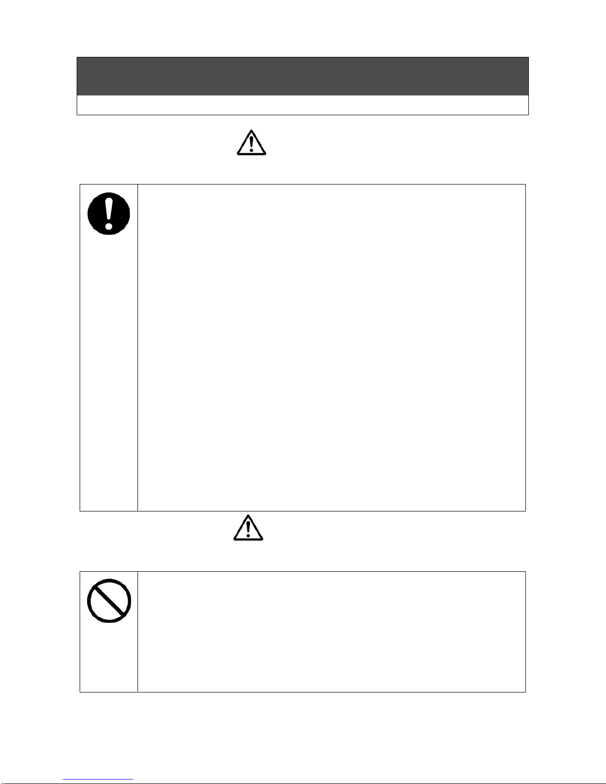
Warning
Indicates a potentially hazardous situation that, if the product is misused, may bring about death or
serious injury to the operator.
Installation must be done by specialized personnel.
The product may fall down or drop if it is improperly installed. It may result in
personal injury, electric shock or fire.
Do not operate this product under abnormal conditions.
Stop the operation when it is abnormal. Then, pull out the power plug or shut off the
main power supply, and consult with our dealer or a specialized company. If the
operation is continued under such conditions, it may cause electric shock or fire.
Shut off the main power supply before cleaning, maintenance and
inspection.
Shut off the main power supply before cleaning, maintenance, and inspection, and
clearly post a sign on the power supply switch to indicate it is under cleaning,
maintenance, and inspection. Failure to do so may result in electric shock or
personal injury.
※Consult with a specialized company for maintenance and inspection.
Inspect the power plug periodically.
If the product is operated with the power plug, periodically inspect the power plug
and confirm it is not covered with dust. The power plug must be fully inserted to the
root of pins. If the power plug is covered with dust or not fully inserted, it may cause
electric shock or fire.
Be sure to install the protective device.
Consult with a specialized company to install an earth leakage breaker. Failure to
do so may cause electric shock or fire. Also, install an overload protection
device (thermal relay). Operation without such a device may cause
malfunction due to overload or fire.
Contact with a specialized company when the earth leakage breaker is
activated.
When the earth leakage breaker is activated, contact with a specialized company. If
you force to turn on the power supply, it may cause electric shock or fire.
Do not use this product outdoors.
This product is intended for indoor use. If the product is used outside and is
exposed to wind or rain, the motor may suffer from incomplete insulation and may
cause electric shock or fire.
Caution
Indicates a critical situation that, if the product is misused, may bring about injury to the operator or
damage to the product.
Do not use the machine over the specified pressure.
If using the machine over the specified pressure, it may shorten the life of product
and may cause failure, abnormal generation of heat or trouble.
Prohibition of operation with the vacuum pipe closed (V type and V・B type)
Do not operate the pump with the vacuum controller closed completely to close the
vacuum pipe. Negligence may cause an abnormal pump temperature rise resulting
in a product failure, protective cover deformation or burn injury.
Do not sit on, lean on, or place objects on this product.
Do not place heavy objects or object containing water on the product, and do not get
on it. If you get on the product, you may fall and be injured. If water spills, it may
cause rust inside or poor insulation and may cause leakage or electric shock.
Page 6
4
Precautions For Safety
Precautions for Use (Caution)
Caution
Indicates a critical situation that, if the product is misused, may bring about injury to the operator or
damage to the product.
Do not operate this product with any voltage other than the rated one
specified for the motor.
Operation with any voltage other than the rated voltage specified for the motor
may
result in failure or accident.
Prevention of melting of distribution cable covering due to contact.
Install the motor so that wiring cables do not touch the motor frame.
Contacting
with cables may result in melting covering or ignition.
Be alert to burn.
Do not touch areas around the dry pump, and the exhaust port and the piping
surface of exhaust side. They are heated to high temperature, and it may result
in burn.
Inspect the earth leakage breaker periodically.
Periodically check performance of the earth leakage breaker. If using the product
with failure of the earth leakage breaker, it may cause electric shock in case of
short circuit.
Installation of check valve
Residual pressure may reverse the rotation when the pump is stopped. Be sure to
install the check valve horizontally within 50cm from the inlet port (or the exhaust
port) of pump. No installation of check valve may cause malfunction.
Turn off the main power supply in case of not using the pump for a long
time.
When you do not use the product for a long time, shut off the main power supply.
Otherwise, it may cause electric shock or short circuit ignition due to
degenerated insulation.
Be sure to wear personal protective equipment for cleaning and
maintenance.
When you carry out cleaning or maintenance, be sure to wear gloves. Failure to
do so may result in injury or burn.
When you transfer the product, be sure to wear nonslip gloves and safety shoes.
Failure to do so may result in injury.
Continuous operation is recommended.
If the start and stop frequency is high, start and stop cycle in 5 minutes or less, it
may cause significant lifetime deterioration or malfunction of the product.
Product Use Limitations
(1) If the unit is to be used as part of critical installations, safety devices and backup
systems which can be switched to should be put into place to insure that serious
accidents or losses do not occur in the event that the unit should break down or
malfunction.
(2) This product was designed and produced as a general purpose device for use in
ordinary manufacturing. Accordingly, this warranty does not apply to nor cover
the following applications. However, in cases where the customer/user takes full
responsibility and confirms the performance of the equipment in advance, and
takes necessary safety precautions, please consult with ORION and we will
consider if use of the unit in the desired application is appropriate.
①Atomic energy, aviation, aerospace, railway works, shipping, vehicles (cars and
trucks), medical applications, transportation applications, and/or any
applications where it might have a great effect on human life or property.
②Electricity, gas, or water supply systems, etc. where high levels of reliability and
safety are demanded.
Page 7
5
Precautions For Safety
Precautions for Use (Caution)
Pull out the power plug to disconnect it.
When the product is used with power plug, pull the power plug to disconnect it.
Pulling the power cord may result in disconnection of part of the core wire, and may
cause generation of heat or deterioration.
Precautions For Safety
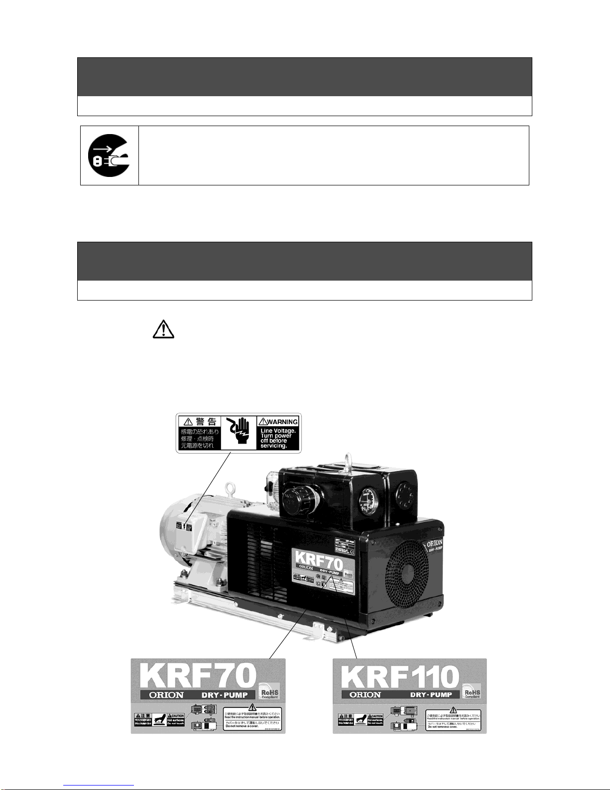
Warning Label Position on the Product
Warning Label Position on the Product
The following warning labels are selected as most important ones out of Safety Information and are
placed on the product. Read the labels before operating the product. When the labels become
unreadable due to scratch or dirt, contact with your dealer to get new ones for replacement.
■Burn
■Electric shock
Page 8
6
Precautions for Proper Operation
■For inlet air, aim at normal temperature and normal
humidity clean air with little dust but free from
corrosive and explosive gases.
※Normal temperature: 0 to 40 deg. C
※Normal humidity: 65% +/- 20% (JIS Z 8703)
■Prohibition of operation in reverse rotation.
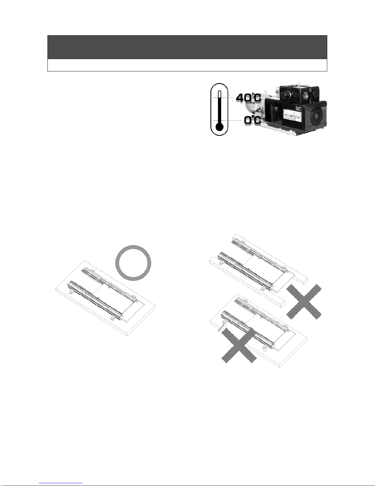
■Set the ambient temperature of the dry pump to the
range of 0 to 40 degrees C.
Try not to cause condensation inside the pump.
■Keep the pump away from oil, water, dust, rain, etc. Also, never lubricate the product.
■Be sure to use under specified pressure or less.
■Do not remove the main cover , and top and bottom partition plates. Removing these cover and plates
may result in shortening the life of product severely due to the temperature rise.
■Install the product on a flat surface..
■Periodically replace consumable parts (see pages 20) and replacement parts (see page 21).
■Be sure to Install the product on the level while whole base is touching on the level surface like in
figure A.
※do not Install the product like in figure B.
Fig.A
Fig.B
Cushion rubber etc
Page 9
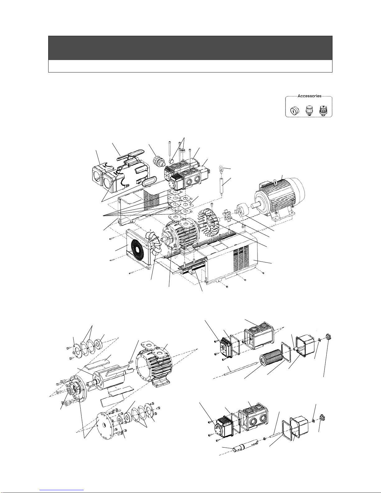
7
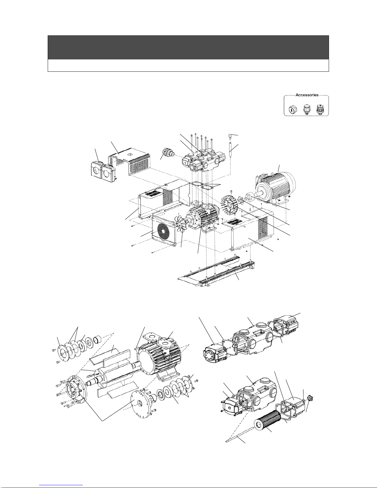
Name of Components
KRF70
※●mark indicates consumable parts that is replaced depending on wear condition when checking.
(Refer to page 20.)
※△mark indicates replacement parts that is replaced
periodically at the specified period.
(Refer to page 21.)
Parallel key
△Bearing
Side Plate(B)
△Blade
Spacer
Roto
r
Spacer
△Bearing
●Liner
Beari
Bearing
Retainer
●Liner
Cylinder
Cap
●Filte
r
Element
●Gasket
Suction case
●Rubber
packing
●Spring tube
Filter Case
●Packing
Knob nut
Long cap 70
●Gasket
Delivery case
Squeezing tube
Muffler
case
Stay bolt
●Rubber
packing
●Packing
Knob nut
Stay bolt
Dry pump deal drawing
Exploded view of filter body
Pump deal drawing
Motor
Main cover 70
No.1
Gauge cover 70
Fan
Base
Attachment
Eyebolt
VC81
●Gasket (B)
Supplementary
bolt
SD case cover
Partition
plate top
VFF-70
Hexagon socket head plug
MFF70
Fan cover 70
Pump
Fan coupling
●Spider
Processing chart of coupling
Main cover 70
No.2
①
②
③
① Compound gauge
●② Vacuum controller VC81
③ Pressure controller PCA8
Page 10
8
Name of Components
KRF110
※●mark indicates consumable parts that is replaced depending on wear condition when checking.
(Refer to page 20.)
※△mark indicates replacement parts that is replaced
periodically at the specified period.
(Refer to page 21.)
Dry pump deal drawing
Exploded view of filter body
Pump deal drawing
Parallel key
△Bearing
Side Plate(B)
△Blade
Roto
r
△Bearing
●Liner
Bearing
Retainer
●Liner
Cylinder
Bearing
Retainer
●Filter
Element F
●Gasket (B)
Suction case
●Spring tube
Filter Case (B)
●Packing
Cap
Delivery case
Muffler
case
Stay bolt
●Rubbe
r
packing
Knob nut
Long cap 100
●Gasket (B)
●Gasket (B)
Motor
Main cover 110
No.1
Gauge cover 110
Fan
Base
Eyebolt
VC100B
●Gasket (A)
Supplementary
bolt
SD case cover
VFF110
MFF110
Fan cover 110
Pump
Fan coupling
●Spider
Processing chart
of coupling
Main cover 110
No.2
①
②
③
① Compound gauge
●② Vacuum controller VC100B
③ Pressure controller PCA10
Page 11
9
Name
plate
Preparation and Confirmation
Before Installation/ Installation
Danger
●Do not use the product where flammable gas or explosive gas may exist.
Warning
●Set up the product where it is protected from water, oil and dust.
●Please use the product indoors.
●Do not set up the product where corrosive gas (chlorine or sulfur dioxide gas) exists.
●Do not set up the product under direct sunlight.
●Use the product where the ambient temperature ranges 0 to 40 degrees in Celsius.
●When you transport the product, lift up with slings.
Before Installation
●The product is heavy. Be careful enough when moving the product.
●Upon receiving the product, check it carefully for signs of
shipping-related damage like scratches, deformation, etc. If
you notice a problem, contact with your dealer.
●Be sure to check the name plate whether purchased product
is
right model as you ordered.
●When the product is delivered with accessories, be sure to
check the accessories whether there are all the parts or not.
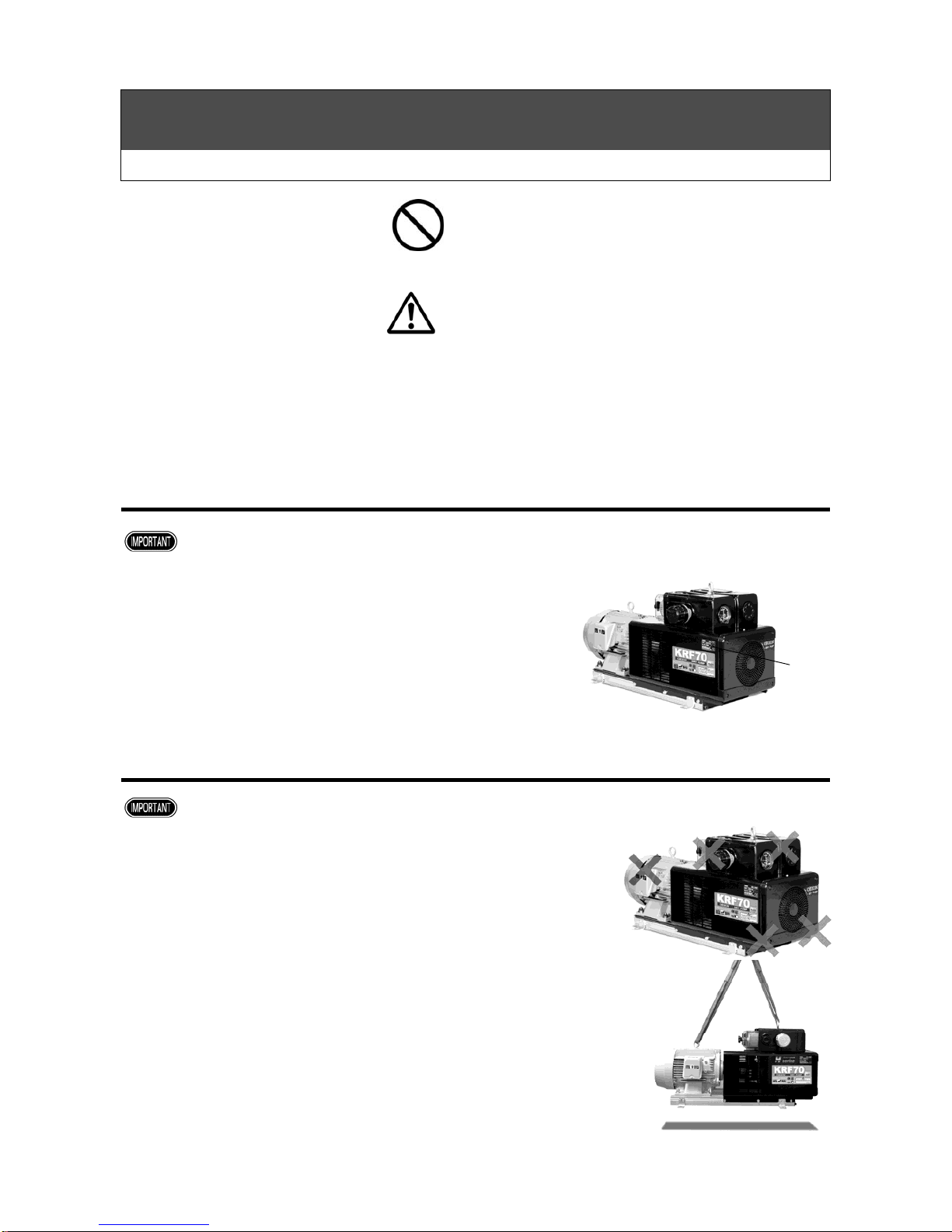
Installation
●
When the product is 25kg or over,
hold the product with two
persons.
Also,
do not hold the terminal box of motor, filter
case, and controller
when holding with two persons.
Holding the
terminal box and filter case of the motor may result in injury,
damage or malfunction if product or parts of it are dropped.
●
In case of using a hanging belt, be sure to belt as shown in the
photo.
Photo
Do not hang a sling fo
r
these parts.
Page 12

10
Preparation and Confirmation
Installation Site/ Gauge & Controller
Installation Site
Warning
●Installation should be carried out by your dealer or special service company. Improper installation
may result in vibration, electric shock, or fire.
●Set up the product in a wide space where you can easily maintain, inspect and overhaul the product.
●Ambient temperature of the pump is 40 deg. C or less. If there is any heat source near the pump, be
sure to check the ambient temperature does not exceed 40 deg. C.
●Using the product in the enclosed space may result in malfunction due to the generation of heat of the
pump. Ventilate adequately around the pump, and be careful not to exceed the permissible ambient
temperature.
●Be sure to install the product horizontally while the whole base plate is touching the level
surface.
Warning
Residual pressure may reverse rotation when the pump is stopped. Be sure to install the check valve
within 50cm from the inlet or outlet port of the pump. No installation of check valve may cause
malfunction.
Gauge & controller
KRF70
Be sure to install the gauge according to following procedure.
※For the controller installation position, refer to the outer dimension drawing provided on P26-28.
※Do not apply a sealing tape when installing the pressure gauge. (Do not overtighten.)
※Do not apply a sealing tape on the threads. After tightening the controller hand-tight, give an
additional quarter to half turn using a tool. Smooth surface due to application of a sealing tape
may result in excessively tightening the controller. This may damage or deform the thread part and
cause malfunction. (There is no need of securing high airtightness using a sealing tape or adhesive
agent because the pump is designed for low pressure/vacuum.)
※Compound gauge is a part that is weak against impacts. Do not hit or drop the product with
compound gauge.
●Installation of check valve
Remove the cover.
Install the gauge.
Push the check point, remove the claw and pull the case foward.
Claw
Press it back in place until
the cover claw is locked.
Page 13

11
Preparation and Confirmation
Gauge & Controller / Piping
KRF110
Be sure to install the gauge according to following procedure.
※For the controller installation position, refer to the outer dimension drawing provided on P29-31.
※Do not apply a sealing tape when installing the pressure gauge. (Do not overtighten.)
※Do not apply a sealing tape on the threads. After tightening the controller hand-tight, give an
additional quarter to half turn using a tool. Smooth surface due to application of a sealing tape
may result in excessively tightening the controller. This may damage or deform the thread part and
cause malfunction. (There is no need of securing high airtightness using a sealing tape or adhesive
agent because the pump is designed for low pressure/vacuum.)
※Compound gauge is a part that is weak against impacts. Do not hit or drop the product with
compound gauge.
Piping
1.Avoid direct connection with steel pipe.
・
Use hose for inlet and exhaust piping. In case of direct connection with steel pipe, resonance with
the piping system
may cause noise or vibration.
For exhaust piping, use heat resistant and
pressure resistant (100kPa or over) hose.
・
Completely remove dirt and dust inside the hose before piping.
2.When intake air contains a big amount of dust, or if dust grains are very fine (10μm or less), use
an appropriate filter in addition to the accessory filter.
3.Install the hose of the exhaust piping system properly in order to prevent condensed water
inside the system from entering the pump, and from discharging from the piping end.
If condensed water in the piping system enters the pump, the pump inside may be locked by rust or the
blades may not come out. To avoid this situation, take the following measures:
①
Install the valve or drain in the exhaust piping system
so that the condensation of water occurred inside the
system can drain out. Also, drain out the collected
condensation of water periodically. (See Figure 1.)
・
Provide valve or drain hose on the pump side in order
to prevent condensed water from entering into the pump.
・
In case of a long piping system, provide valve or drain
hose in the halfway of the system.
・
When condensed water discharges from the piping
end, install a valve or drain hose at the piping end.
②If the pump is not frequently used, idle the pump for 10 to 15 minutes after finishing
operation.
Remove the cover.
Install the gauge.
Push the check point, remove the claw and pull the case foward.
Claw
Press it back in place until
the cover claw is locked.
(Figure 1)
Piping end side Piping end side
Drain or valve
Page 14

12
Preparation and Confirmation
Piping / Electrical Wiring
4.If reverse rotation is caused by residual pressure upon stopping the
pump, blade damage is likely to be incurred. Please install a check
valve within 50 cm from the pump's inlet port (or exhaust port) to
prevent this from happening. In installing a check valve, install it
levelly to the floor. Negligence may cause pulsation or abnormal
noises. (Figure 2)
(Recommended check valve: manufacturer's product name: JIS
compliant KITZ bronze swing check valve)
5.Do not apply a sealing tape when connecting pipes. Pieces of torn
sealing tape may cause controller malfunction or abnormal operation sound.
6.Do
not overtighten pipes. Overtightening pipes may damage the SD case.
Electrical Wiring
Warning
●Contact with a specialized company to install an earth leakage breaker. Failure to do so may cause
electric shock or fire. Also, install an overload protection device (thermal relay). Failure to do
so may cause failure to the product due to overload or fire.
1.Install the earth leakage breaker.
Set the breaking capacity to 1.5 times the current value shown on the motor name plate as a rough
guiding value. Select a sensed current of 30mA.
※
Consult with a specialized company for electrical installation.
2.Be sure to install the grounding.
・Location of grounding screws:
The grounding is attached on the terminal box.
(You can find the mark "E" or mark "
" near the screw.)
・Select a copper wire, with a nominal cross section bigger than the cross section shown in the
example, as grounding wire.
Motor rated output (kW) Nominal cross section(mm
2
)
2.2 2
3.7 3.5
・When the grounding screw becomes loose due to vibration during operation, sparks will occur at the
grounding section. Wire the grounding cable so that the grounding screw does not loose due to
vibration during operation, and tighten the screw with locking.
3.Install the overload protection device (e.g. thermal relay). Make the V specification 100%, and
B and VB specifications 110% against the rated current value written on the motor name plate
for the set value.
4.Operate the pump with the rated power supply written on the motor name plate.
5. A special characteristic of the dry pump is that during initial operation, the rated current value
may be exceeded at the start, but will drop over time.(Note that depending on the specifications
and/or operating conditions, there are cases it may not drop to the rated current value or
below.) Consult with your dealer if the overload protector (thermal relay) activates during initial
operation or during normal operation.
6.Select a power cord referring to the current value shown on the pump name plate.
7.Be sure to keep the power supply cable with holding assembly in order not to get stressed to
the internal power supply connection terminal at the time of pulling the cable.
(Recommended holding assembly: Maker; UI Lapp GMBH/ Product name: Skintop/ Model: ST-M,
STR-M)
(Figure 2) Example of chec
k
valve installation
Check valve
Page 15

13
Preparation and Confirmation
Electrical Wiring
7.Motor name plate (V, B, or VB enters into the □.)
・Matsushita-made motor is mounted for three-phase specification. Mitsubishi-made motor is
mounted as standard for single-phase specification.
Operation Procedure
Check before Operation/ Operation
Check before Operation
■Install the earth leakage breaker.
※Consult with a specialized company for electrical installation.
■Install the overload protection device (e.g. thermal relay). Make the V specification 100%, and B and
VB specifications 110% against the rated current value written on the motor name plate for the set
value.
■Before using a machine that has not been used for a long period of time, be sure to check that the
power is off, and then rotate the rotor (fan, motor fan etc.) gently to confirm that it can be rotated
smoothly.
■Compound gauge is a part that is weak against impacts. Do not hit or drop a product with compound
gauge.
■When storage temperature and operation temperature are differing more than 10 degrees in Celsius,
leave the pump at the operation site for more than 2 hours in order to eliminate the temperature
difference before using.
If condensation water occurred, and the condensation water enters into the pump, it may result in rust,
lock, and vanes might block.
■KRF70-□-04, KRF70-□H-04
■KRF110-□-04
■KRF70-□-01, KRF70-□H-01 ■KRF110-□-01
Page 16

14
Operation Procedure
Operation
Operation
1.Turn the control screw in the direction of (-) .
2.Be sure to check by inching that the rotating direction is the
same as the one shown on the "rotating direction arrow"
when it is viewed from the motor fan side.
3. Turn on the power switch.
4. Use the controller to adjust
vacuum level and exhaust pressure.
Check: Be sure to check the rotating direction.
Adjustment of vacuum level and exhaust pressure
■Adjustment of vacuum level
(Vacuum controller)
1.Turn the locking nut clockwise to unlock the control screw.
2.Turn the control screw until the desired vacuum level is obtained on the gauge.
3.Turn the locking nut counterclockwise to lock th e control screw.
■Adjustment of exhaust pressure
(Pressure controller)
1.Turn the control screw until the desired exhaust pressure is obtained on the gauge.
「Rotating direction arrow」
Adjustment of vacuum level
- vacuum +
Adjustment of exhaust pressure
- pressure +
Control screw
Locking nut
Control screw
Vacuum controller
Pressure controller
Page 17

15
Operation Procedure
Pressure range during operation / How to Correct Vacuum Level (Gauge Pressure) /Stop
Pressure range during operation
kPa KRF70・110(Standard) KRF70(High-pressure)
■
Use as vacuum
pump
(V type)
Continuous
operative
vacuum
60 or lower 80 or lower
■
Use as blower
pump(B type)
Continuous
exhaust
pressure
60 or lower 70 or lower
■
Use as vacuum
pump and
blower pump
(V, B type)
Continuous
operative
pressure
Total of continuous operative
vacuum and continuous exhaust
pressure 60 or lower
Total of continuous operative
vacuum and continuous exhaust
pressure 80 or lower
※1 Recommended range: The pump operating under 1 atmospheric pressure can exert its optimal
performance (life, operation noise, etc.) at a vacuum/pressure within this range.
Use the pump within the recommended range unless the higher vacuum/pressure is required.
※Contact with Orion or Orion dealer for other usage.
How to Correct Vacuum Level (Gauge Pressure)
Correction formula: A = C +(101.3- B)
A : Vacuum level at 1 atmosphere kpa
B : Atmospheric pressure at vacuum level measuring position kpa
C: Reading on compound gauge kpa
Ex) When the reading on the compound gauge is 76kPa and the atmospheric pressure is 973hPa
(97.3kPa), the vacuum level at 1 atmosphere is calculated as follow:76 + (101.3 – 97.3) = 80kPa
To read the accurate vacuum level, use a mercury manometer or an equivalent meter based on
absolute pressure.
Atmospheric pressure conversion formula (hPa → kPa)
B(kPa)=B(hPa)÷10
Stop
Shut off the power switch.
Page 18

16
Spring T ube
Filter case/ Muffler case
Filter Element
Delivery element
Knob Nut Assy
Paking
Rubber Paking
Maintenance and Inspection
Cleaning of filter element
Warning
Turn off the main power supply before cleaning, maintenance and inspection.
Turn off the main power supply before cleaning, maintenance and inspection, and clearly post a sign on
the power supply switch to indicate it is under maintenance. Failure to do so may result in electric
shock or personal injury.
※Consult with a specialized company for maintenance and inspection.
Do not wash filter element with organic solvents.
When cleaning the filter element, do not use organic solvents such as thinner, alcohol, benzine,
gasoline, and kerosene. It may result in explosion or fire.
Caution
Be sure to wear protective wear.
When you carry out cleaning or maintenance, be sure to wear gloves. Failure to do so may result in
injury or burn.
When you transfer the product, be sure to wear nonslip gloves and safety shoes. Failure to do so may
result in injury.
1. Cleaning of Filter Element and Delivery element
When debris deposits on the filter element, remove
the filter case and muffler case, and then remove
the filter element and the delivery element to get rid
of the debris with an air blow. If a fouled filter
element cannot be cleaned with air blows, replace
it with a new one.
Inspection period Contents
Once a week Remove dust or dirt
Page 19

17
Maintenance and Inspection
Cleaning of Filter Element
2. Cleaning of Controller
(Vacuum controller, pressure controller)
If the sheet surface of the controller is very dirty, the
function may deteriorate. Disassemble the
controller periodically, and remove the dirt of each
part.
3. Inspection of Piping
Be sure to tighten the knob nut of filter case surely
and ckeck that there is no air leakage, clogging, or
loosening in the piping.
Inspection period Contents
Once a month
Disassembly
cleaning
Inspection period Contents
Once a month
Air leak, clogging,
looseness of
tightened parts
(Vacuum controller) (Pressure controlle r)
VC81(KRF70) VC100B(KRF110) PCA8(KRF70) PCA10(KRF110)
Sheet surface
Sheet surface
Sheet surface
Sheet surface
Page 20

18
Troubleshooting
Warning
Turn off the main power supply before cleaning, maintenance and inspection.
Turn off the main power supply before cleaning, maintenance and inspection, and clearly post a sign on
the power supply switch to indicate it is under maintenance. Failure to do so may result in electric
shock or personal injury.
※Consult with a specialized company for maintenance and inspection.
Caution
Be sure to wear protective wear.
When you carry out cleaning or maintenance, be sure to wear gloves. Failure to do so may result in
injury or burn.
When you transfer the product, be sure to wear non-slip gloves and safety shoes. Failure to do so
may result in injury.
Check abnormal factors.
Page 21

19
Troubleshooting
Condition Cause Corrective action
Vacuum level
does not
increase.
Filter element is clogged with dust, and air cannot
be taken in.
Remove the element and blow off
dust from the element with
compressed air.
If the element becomes dirty,
replace it with a new one.
Oil entered into the pump, and the vane cannot
come out.
Consult with our dealer or service
personnel.
Foreign object entered into the pump and the
vane cannot come out.
Due to rust inside of the pump by intaking water,
the vane cannot come out.
Due to condensation inside of the pump, the vane
cannot come out.
Damage to meter Replace the meter.
Tightening of filter case, piping, air tank are not
tightened well, and air leaks.
Consult with our dealer or service
personnel.
The coupling fixing bolt is loose.
Decreased pump rotating speed due to motor
malfunction.
Damaged vane.
Worn vane.
When an
abnormal
noise is heard
or when the
meter shows
pulsations.
An abnormal noise is occurred because the
pressure is out of allowable range.
Return the pressure to the
applicable pressure range.
Excessive exhaust pressure causes an abnormal
noise.
Adjust the exhaust resistance to
return the exhaust pressure to
normal.
The abnormal noise occurs due to misfitting of the
coupling.
Consult with our dealer or service
personnel.
The abnormal noise occurs due to burning of the
motor.
The abnormal noise occurs because mounting
bolts became loose.
Damage to meter. Replace the meter.
Filter element is clogged with dust, and air cannot
be taken in.
Remove the element and blow off
dust from the element with
compressed air.
If the element becomes dirty,
replace it with a new one.
Oil entered into the pump, and the vanes cannot
come out.
Consult with our dealer or service
personnel.
Due to condensation inside of the pump, the
vanes cannot come out.
The vanes were broken because foreign object(s)
entered into the pump.
When pump
is stopped.
The vanes were broken because foreign object(s)
entered into the pump.
The rotor was touched because the pressure was
out of applicable pressure range.
Defective electromechanical system
Page 22

20
Consumable parts
List of Consumable Parts
List of Consumable Parts
(Parts to be replaced depending on wear condition when checking.)
Name of Parts Model KRF70 KRF110
Filter element
(Inlet side)
Parts Number 04000451010 04041878010
Quantity /unit 1
Inspection period Every week
Replacement criterion
When it was damaged, or when dirt cannot be removed by blowing air.
Delivery element
(exhaust side) ※3
Parts Number 04044336010 04101351010
Quantity /unit 1
Inspection period Every week
Replacement criterion
When it was damaged, or when dirt cannot be removed by blowing air.
Gasket
(Cylinder side)
Parts Number 04010287010 04002846010
Quantity /unit 4 2
Inspection period At the time of removal of Suction case to Delivery case
Replacement criterion
When it was damaged or crushed.
Packing
Parts Number 04001458010
Quantity /unit 2 1
Inspection period At the time of removal of Suction case to Delivery case
Replacement criterion
When it was damaged or crushed.
Rubber packing
Parts Number 03042560010 04006914010
Quantity /unit 2 1
Inspection period At the time of check and replacement of element
Replacement criterion
When it was damaged or crushed.
Gasket
(Suction side)
(Delivery side)
Parts Number 03042561010 04000020010
Quantity /unit 2
Inspection period At the time of removal of Suction case to Delivery case
Replacement criterion
When it was damaged or crushed.
Liner
※1
Parts Number 040000410□0 040028390□0
Quantity /unit To be decided by actual positioning.
Inspection period At the time of replacement of vane.
Replacement criterion
When it was damaged.
Spring tube
Parts Number 04042925010 04042925020
Quantity /unit ※2
Inspection period At the time of check and replacement of element
Replacement criterion
When it was damaged or crushed.
Spider
Parts Number 04101313010
Quantity /unit 1
Inspection period Six months
Replacement criterion
When it was damaged or crushed.
VC81
Parts Number 03000205020 ―
Quantity /unit 1 ―
Inspection period Once a month ―
Replacement criterion
When surface of control screw and
valve were abrade away.
―
VC100B
Parts Number ― 03044148020
Quantity /unit ― 1
Inspection period ― Once a month
Replacement criterion ―
When surface of control screw and valve
were abrade away.
※1 Parts number of second digits from the right side differs depending on thickness.
0.2t (white) becomes 1, 0.1t (black) becomes 2, 0.05t (yellow) becomes 3, 0.03t (red) becomes 4.
※
2 (1) 1 pc for vacuum models.
( KRF70-V-01・04) ( KRF70-VH-01・04)
( KRF110-V-01・04)
(2) 2 pcs for blower, and vacuum & blower models.
( KRF70-B-01・04) ( KRF70-VB-01・04)
( KRF70-BH-01・04) ( KRF70-VBH-01・04)
( KRF110-B-01・04) ( KRF110-VB-01・04)
※
3 (1) B lower, and vacuum & blower models only.
( KRF70-B-01・04) ( KRF70-VB-01・04)
( KRF70-BH-01・04) ( KRF70-VBH-01・04)
( KRF110-B-01・04) ( KRF110-VB-01・04)
Saction ・Delivery side gasket
Cylinder side
g
asket
Page 23

21
Consumable parts
List of Motor Maintenance Cycle / List of Replacement Parts
List of Motor Maintenance Cycle
Name of parts Model
KRF70 KRF110
Motor
Three-phase
200V spec.
Parts no. 0A001675000 0A001676000
Model
Toshi ba IK-FCKA21
2.2kW 6P
Toshi ba IK-FCKA21
3.7kW 6P
Qty. 1
※
Maintenance cycle 20,000Hr
Motor
Three-phase
400V spec.
Parts no. 0A001677000 0A001678000
Model
Toshi ba IK-FCKA21
2.2kW 6P
Toshi ba IK-FCKA21
3.7kW 6P
Qty. 1
※
Maintenance cycle 20,000Hr
※Time on the list is the time that possibility to reaching the friction damage range becomes high. It is
not necessary to replace the motor on time because it differs depending on the installation site.
However, be sure to replace and repair the motor whenever troubles happen.
List of Replacement Parts
(Parts to be replaced periodically at specified period.)
(V,B, or VB enters into the □)
Name of parts Model KRF70-□ KRF-□H KRF110-□
Vane
Parts Number
04101504010 04101504010 04100653010
Quantity /unit 6 6 6
Replace-ment time
10,000 6,000 5,500
Bearing
Parts Number 0A000332000 0A000332000 0A000333000
Quantity /unit 2 2 2
Replace-ment time
10,000 6,000 5,500
※Consider the replacement time as a guide, and carry out the periodic replacement.
※Advanced technologies are required to replace vanes and bearings, so contact with our dealer or
service personnel.
※Exchange bearings at the same time when you exchange vanes.
※The indicated blade replacement period is recommended in order to help prevent breakdown due to
blade wear, and assumes average blade wear at 60Hz operation; specific performance is not
guaranteed. The blade might not last as long as the above specified replacement time due to higher
than normal wear from operating environments with low humidity or high temperatures, etc.
The blade should be replaced soon if performance decreases or noise levels increase.
※If the blade is not replaced periodically, progressive wearing down of the the blade height and
thickness can result in the blade being damaged which could lead to the pump becoming inoperable.
Page 24

22
Consumable parts
List of Replacement Parts / Maintenance of plastic parts affecting operation safety
Use the maintenance kit for replacement parts.
Name of Parts Unit
Maintenance kit
Assembly 70
Maintenance kit
Assembly 110
Model KRF70 KRF110
Parts no. 04101347010 04101348010
Items
Vane
Pcs/Unit
6
Bearing 2
Liner (white) 2
Liner (black) 2
Liner (yellow) 4
Liner (red) 6
Maintenance of plastic parts affecting operation safety
Caution
Replace the following plastic parts affecting operation safety promptly upon detection of breakage or
deformation. Failure to do so may cause personal injury.
Name of Parts Model
KRF70
KRF110
Front cover 70
Parts Number
03101467010 ―
Quantity /unit
1 ―
Fan cover
Parts Number
― 03101469010
Quantity /unit
― 1
Front cover 70
Front cover 110
KRF70 KRF110
Page 25

23
Storage(Not in Use for a Long Time)
Storing method / Storage location
St oring method
Pay attention to formation of rust if the pump is not used immediately after received or if the regularly
used pump has not been used for a long time.
St orage location
1.Store the product indoors and place the cover on the pump to protect it from water and dust.
2.Store the product where it is protected from water, oil and dust.
3.Store the product in a dry and clean place.
4.Store the product in an airy place where the ambient temperature is 40 degrees in Celsius or less.
5.Do not store the product where toxic gas such as chlorine gas or sulfur dioxide gas, which corrodes
the pump, is generated.
6.Store the product in a low humidity place to prevent the pump from rusting.
Disposal
Be sure to entrust the disposal of the Product to the specialists in the trade of disposal of industrial
wastes, observing Law about Disposal of Wastes and the Cleaning.
Page 26

24
Specifications
Specification list
Specification list
(V,B, or VB enters into the □)
Model ※1 KRF70-□ KRF70-□H KRF110-□
Designed capacity L/min 1130 / 1350 1850 / 2200
Speed ※2 rpm 930 / 1110 940 / 1120
Ultimate vacuum kPa 90 or more
Continuous operative (V) kPa 60 or less 80 or less 60 or less
Continuous exhaust (B) kPa 60 or less 70 or less 60 or less
Continuous operative (VB) kPa
Total of vacuum level
and exhaust pressure:
60kPa or lower
Total of vacuum level
and exhaust pressure:
80kPa or lower
Total of vacuum level and
exhaust pressure:
60kPa or lower
Diameter of piping connection Rc1 Rc1-1/4
Power supply
※2, ※3, ※4
Three-phase
200V spec
Hz
200V-50/60, 220V-60
Three-phase
400V spec
380V-50, 400V-50/60, 415V-50, 440V-60, 460V-60
Motor
Three-phase
200V spec
kW 2.2(6P) 3.7(6P)
Three-phase
400V spec
Rated current
※2
Three-phase
200V spec
A
10.4/9.6 (200V-50/60Hz)
9.2 (220V-60Hz)
16.2/15.6 (200V-50/60Hz)
14.6 (220V- 60Hz)
Three-phase
400V spec
5.4 (380V-50Hz)
5.2/4.8 (400V-50/60Hz)
5.2 (415V-50Hz)
4.6 (440V-60Hz)
4.5 (460V-50Hz)
8.2 (380V-50Hz)
8.1/7.8 (400V-50/60Hz)
7.9 (415V-50Hz)
7.3 (440V-60Hz)
7.1 (460V-50Hz)
Mass ※2
Three-phase
200V spec
kg 75 120
Three-phase
400V spec
Operation noise
Three-phase ※2
(V)
dB
67/68 73/74 74/75
(B) 74/76 76/77
Applicable
environment
Installation site Indoor
Permissible ambient
temperature
0 to 40 deg.C
Suction air ※5
"Normal temperature:0 to 40 deg.C , Normal humidity:65±20% (JIS Z 8703)
Conditions where there is no corrosive and explosive gas exist.
Clean air without vapor and dew condensation, and less dirt and dust."
Altitude of installation
1000m or less
Pollution Degree Pollution Degree 3 (Worse environment than normal environment)
Overvoltage classification ※6 Classification 3 (supply from the fixed wiring facility)
※1 Only three-phase specification is complied with CE ma rking.
※2 V al ues sh own are with ou r st and ard moto r.
※3 Allowable intermittent power supply voltage fluctuation range is ±10% of the specified voltage; allo wable
sustained supply voltage fluctuatio n range is ±5% of the specified voltage.
※4 Voltage specifications for motors other than our standard ones are according to power supply
specifications specifications shown on the motor name plates.
※5 Consult with your dealer if the product is used in extremely low humidity for adjustment. It may cause the
malfunction of pump.
※6 Refer to IEC664-1.
Page 27

25
Specifications
EC Declaration of Conformity
EC Declaration of Conformity
■This EC declaration of conformity applies only to models that are equipped
with ORION specified 3 phase motors. Models with single phase motors,
models without motors, and those models where the CE marking is not
printed on the machine name plate are not CE approved.
Page 28

26
Dimensional Outline Drawing
KRF70-V-01,04 / KRF70-VH-01,04
(unit : mm)
Page 29

27
Dimensional Outline Drawing
KRF70-B-01,04 / KRF70-BH-01,04
(unit : mm)
Page 30

28
Dimensional Outline Drawing
KRF70-VB-01,04 / KRF70-VBH-01,04
(unit : mm)
Page 31

29
Dimensional Outline Drawing
KRF110-V-01,04
(unit : mm)
Page 32

30
Dimensional Outline Drawing
KRF110-B-01,04
(unit : mm)
Page 33

31
Dimensional Outline Drawing
KRF110-VB-01,04
(unit : mm)
Page 34

37
memo
Page 35

37
memo
Page 36

K No.0322 ’12.2.1 C DG TY
 Loading...