

Page 1

Orion i Series Welding System
User Manual
Page 2

i Series User Manual
Table of Contents
Chapter 1: Welder Setup and Assembly ..................... p.3
What is in the Box ....................................... p.3
Mount the Microscope Arm ............................. p.3
Microscope Arm Setup ................................. p.4
Welder Connection Setup . . . . . . . . . . . . . . . . . . . . . . . . . . . . . . . p.4
External Power Supply Setup ........................... p.5
Shielding Gas Setup .................................... p.5
Adjustments on the Microscope Arm ................... p.6
True Color Optical LCD Shutter ......................... p.6
Become Familiar with the Microscope .................. p.7
Electrode Setup ......................................... p.7
Make a Weld ............................................. p.9
Chapter 2: User Interface Overview ......................... p.10
Header Area ............................................ p.10
Waveform Graph Area .................................. p.10
Metals Tab - Controls Area ............................. p.10
Arc Tab - Controls Area ................................. p.11
Additional Information on Seam Mode ................. p.14
Seam Mode Advanced Screen .......................... p.14
Tack Tab - Controls Area . . . . . . . . . . . . . . . . . . . . . . . . . . . . . . . . p.16
Video Tab ............................................... p.16
Load Tab ................................................ p.17
Save Tab ................................................ p.17
Settings Tab ............................................ p.17
Chapter 3: Reading the Waveform Graph .................... p.18
Ignition .................................................. p.18
Waveforms ............................................. p.19
Weld Time . . . . . . . . . . . . . . . . . . . . . . . . . . . . . . . . . . . . . . . . . . . . . . . p.20
2
Orion Welders
1693 American Way, Unit 5
Payson, UT 84651 USA
+ 1-801-658-0015
Page 3
Chapter 1: Welder Setup & Assembly
What is in the Box
BOX
e Orion i2 Series System will arrive in 1 box.
MAIN BOX:
(1) User Manual & Getting Started/Quick Setting Guide
(1) Orion i2 Power Supply
(1) Orion i2 Microscope Arm
(1) Orion i2 Microscope Extender Arm
(1) Orion i2 Microscope Arm Table Mount
(1) Orion i2 Microscope Arm Support Bar
(1) Orion i2 Interface Box
(1) Orion i2 10 pin power cable
BOX WITHIN MAIN BOX:
(1) Welder Power Cord
(1) Stylus Hand Piece
(1) Pair Alligator Clips
(1) Foot Pedal
(1) Shielding Gas Hose
(1) Cross Lock Tweezers
(1) Electrode Vile (5x 0.5mm -- 5x 1.0mm Electrodes – 1x
Diamond Dremel Disk – 1x 0.5mm Orion Collet)
(1) Fiberglass Brush
(1) Stainless Steel Weld Sample Card
(1) 3 Allen Wrenches with green microscope protective cover
(1) Pair Microscope Eye Piece Shields
(1) Loop Closing Pliers
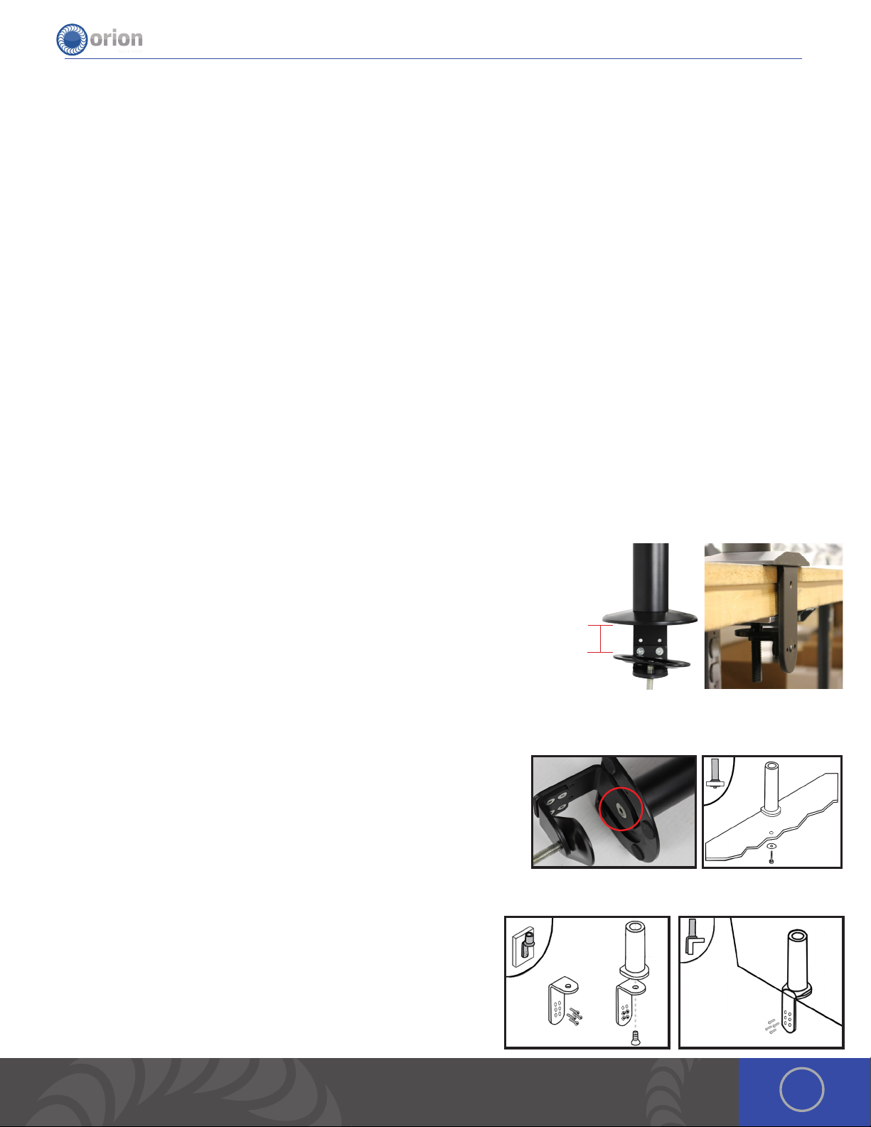
Mount the Microscope Arm
MOUNTING OPTION 1 CLAMP TO TABLE
• 1. Determine the height of the tabletop. *If it is thicker than 2-3/4’ (7cm), follow arm base mounting options 2 or 3.
• 2. Position the microscope arm clamp under the tabletop.
• 3. Place the included allen wrench in the opening at the bottom of the clamp
bolt. Turn the bolt clockwise until the clamp is very snug.
2¾”
MOUNTING OPTION 2 BOLT THROUGH TABLE
1. Using the provided allen wrench, unscrew the 10m x 1.5 allen bolt underneath the arm base.
2. Drill a 3/8’ (10mm) hole through the tabletop.
3. Place a washer on the 10m x 1.5 bolt (length will depend on tabletop thickness) and run it up through the tabletop into
the arm base.
4. Tighten the bolt until it is very snug.
MOUNTING OPTION 3 BOLT TO TABLE
1. Position the base against the table.
2. Trace drill holes with a pen or marker.
3. Drill 1/4’ holes in the tabletop.
4. Run screws through the base into the drilled holes.
3OrionWelders.com
Page 4
i Series User Manual
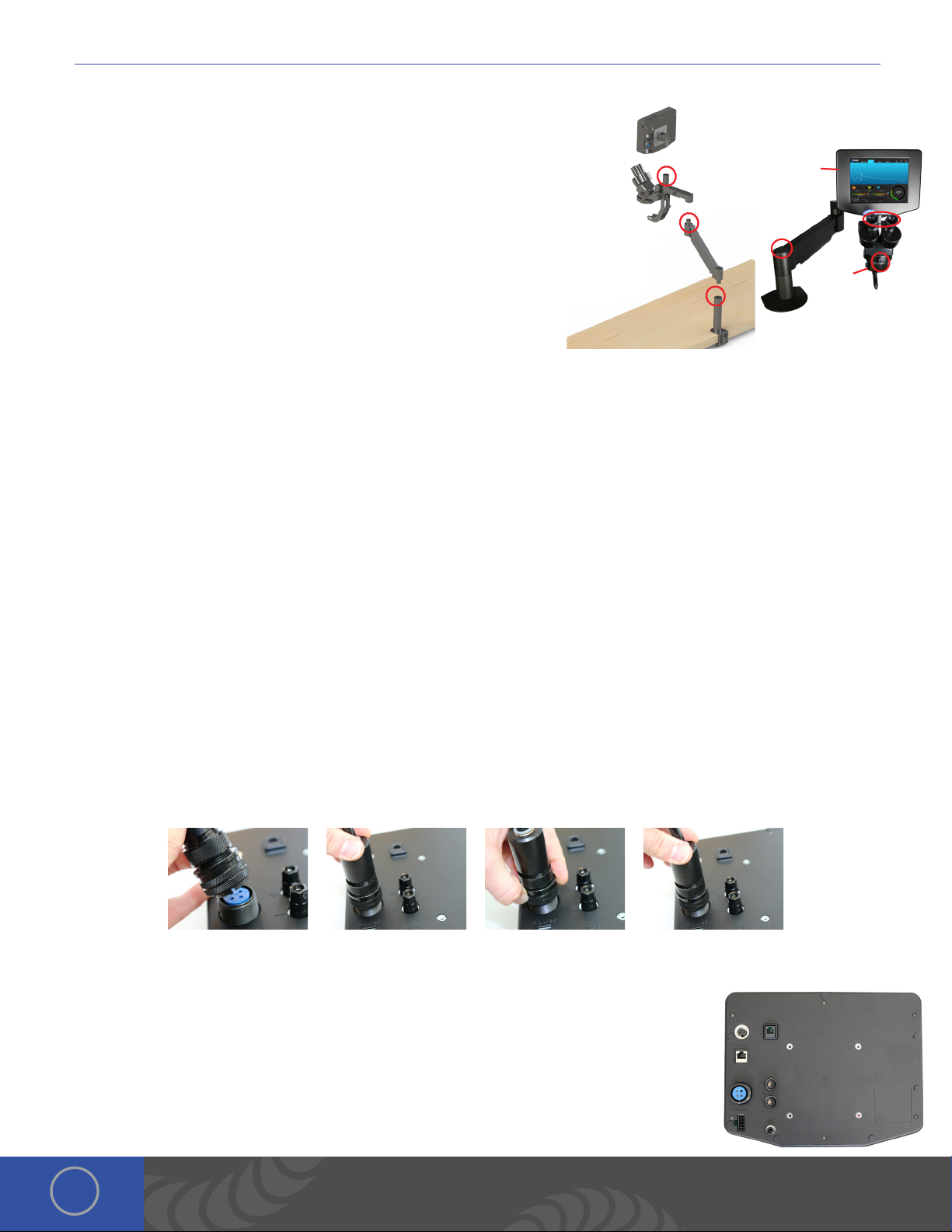
Microscope Arm Setup
1. Place the microscope extender arm into the arm base.
2. Place the microscope arm into the top of the extender arm.
3. Place the touch screen box into the slot on the microscope arm above
the microscope optics.
4. Loosen/tighten the allen on the top of the microscope extender arm
to adjust the spring pressure. Turn the allen counter clockwise if the
arm does not hold the microscope up. Turn the allen clockwise if the
arm does not allow the microscope to come down.
5. Ensure the RJ45 microscope cable is plugged into the RJ45 port on the
light ring (below the microscope optics).
6. Plug the other end of the microscope cable into the RJ45 “Shutter”
port on the back of the touch screen box. *Orion RJ45 ports are not compatible with any other RJ45 ports. Connecting
them to other devices may damage the welder and/or the other devices.
7. Install the rubber eyepiece covers onto the optics.
8. Loosen the bolt in front of the microscope mount to move the microscope head left and right.
*When adjusting the spring pressure as described in step 4, be sure the arm is parallel to the table as seen here.
3.
2.
4.
1.
6.
7.
5.
8.
Welder Connection Setup
CONNECT THE WELDING STYLUS TO THE BACK OF THE TOUCH SCREEN BOX
e welding stylus requires the most attention during setup. Since argon gas will flow through the stylus, a tight fit between
the power supply and the stylus is critical. is will insure that no oxygen is entrained into the weld. To accomplish this,
follow the steps below.
1. Position the end of the stylus so that the notch is facing down.
2. Push the stylus into the stylus connector port on the back of the touch screen box.
3. Turn the outside layer of the stylus connector clockwise so it screws onto the stylus connector port.
4. Continue to turn the outside layer of the stylus connector clockwise until it stops.
5. Now push in on the stylus connector, (you will feel it move in a couple centimeters). en turn the outside layer of the
stylus connector clockwise until it stops.
6. Repeat steps 2-5 until you feel the stylus connector bottom out, and you can no longer screw the stylus connector
clockwise. is will insure that the stylus connector is firmly seated.
CONNECT THE REMAINING CABLES TO THE BACK OF THE TOUCH SCREEN BOX
1. Place an alligator clip into the positive port on the back of the touch screen box. *Remember
to attach the alligator clip to the work-piece before welding.
2. Plug the foot pedal into the “trigger” port on the back of the touch screen box.
3. Verify that the RJ45 cable is securely fastened in the RJ45 port.
4. Insert the 1/4” gas tube firmly into the “Gas” port. *It may wiggle when connected, but
should not come out if pulled on.
4
Page 5
CONNECTOR PORTS ON THE BACK OF THE INTERFACE BOX
1. Foot Pedal Connection Port.
2. Shutter/Darkening Lens Connection Port.
3. Stylus Connection Port
4. Power Supply Connection Port
5. External Device Port
6. Positive Grounding Port (Use for Arc Welding)
7. Negative Grounding Port (Use with Positive when Tack Welding)
8. Inert Gas Connection Port
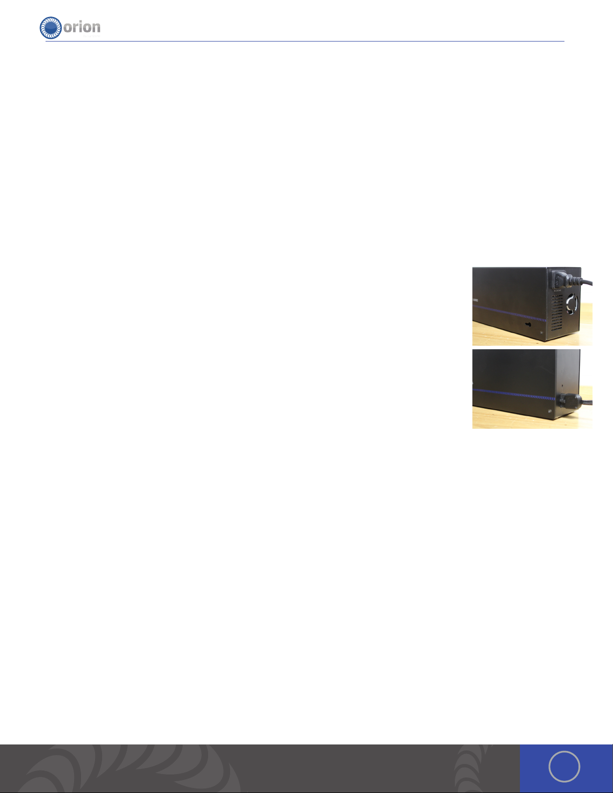
External Power Supply Setup
SET UP THE EXTERNAL POWER SUPPLY
e Orion has an internal switching power supply that can accept 90VAC to 240VAC.
1. Plug the female end of the power cable into the “AC Power” port on the side of the external
power supply.
2. Connect the male end of the power cable into AC power.
3. Plug the 10 pin “external power supply to touch screen box“ cable into the 10 pin port on the
external power supply.
4. Run the cable from step 3 to the microscope extender arm. Remove the plastic piece on the
underside of the microscope extender arm by squeezing the plastic piece on both ends with
your thumb and index fingers.
5. Place the cable in the plastic piece.
6. Connect the plastic piece back to the extender arm.
7. Plug the end of the cable into the 10 pin port on the back of the touch screen box.
8. e red LED indicates that the power supply has AC power applied and is ready to use.
Shielding Gas Setup
During the pulse-arc welding process high temperature plasma quickly melts metal into a molten pool. As the weld is
performed, a small amount of shielding gas is released through the weld stylus to prevent oxygen from entering the molten
pool. After the weld has occurred the protective gas turns off. If oxygen from the air enters this molten pool, the result is a
metal oxide that is brittle, porous and burnt-looking. Protective shielding gas is used, such as 99.996% pure Argon (Argon
4.6) or higher, to prevent these effects. Shielding gas is necessary to produce clean and repeatable pulse-arc welds. We
recommend high purity argon. is can be purchased at your local welding supply shop.
PRESSURIZED GAS SAFETY
1. Always secure the pressurized gas tank to a fixed location (such as a sturdy table leg). If the pressurized gas cylinder
were to tip and become damaged there is possibility that the tank could become rocket-like, expelling the high pressure
shielding gas as propellant.
2. ALWAYS TURN OFF THE SHIELDING GAS AT THE MAIN VALVE WHEN FINISHED. is will help your shielding gas supply
last longer in case there is a small leak in the tubing. is is also a good safety practice. If the tube becomes dislodged,
shielding gas could fill the room displacing needed breathing oxygen. Argon is heavier than air and will fill the room from
the bottom upward. If you experience a large shielding gas leak, open all of the doors and windows in the room.
5OrionWelders.com
Page 6
i Series User Manual
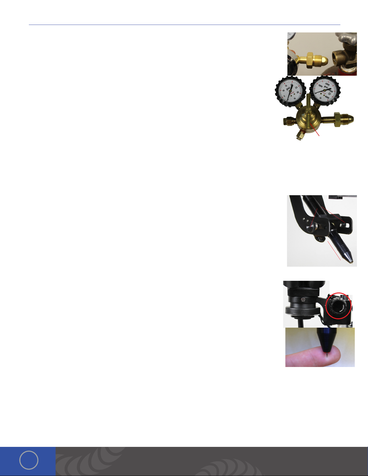
SHIELDING GAS TANK AND REGULATOR SETUP
1. Ensure that your shielding gas tank is securely fastened to a stationary point near the welding
area.
2. Turn the regulator dial COUNTER CLOCKWISE (closed) until it is fully backed out to prevent
over-pressurization of the line.
3. Screw the gas regulator onto the shielding gas tank.
4. Connect one end of the gas tubing into the gas regulator. It will stop when it is fully
connected. Tug gently on the tube to verify a tight fit.
5. Insert the other end of the gas tubing into the gas port on the back of the power supply.
It will stop when it is fully connected. Tug gently on the tube to verify a tight fit.
6. Open the gas tank slowly. e dial on the right should pressurize and the dial on the
right should remain at zero (when the regulator dial is fully backed out – see step 2).
7. Slowly turn the regulator dial CLOCKWISE until the gas pressure reads between 7-10 psi.
(is will adjust the dial on the left side of the regulator.)
Adjustments on the Microscope Arm
ADJUST WELDING STYLUS POSITION
1. Insert the welding stylus into the stylus holder under the microscope head then tighten the
stylus holder knob.
2. Loosen the screws on either side of the stylus holder.
3. Adjust the welding stylus to a 45-degree angle then slightly tighten the screws just enough to
hold the stylus in place at a 45-degree angle
4. While looking through the microscope, slide the welding stylus holder forward/backward until
the tip of the stylus is in the center of your focus.
5. Now securely tighten the stylus holder screws.
4.
Regulator Dial
1.
2. 45°
ADJUST THE MICROSCOPE FOCUS
1. Twist the large dial on either side of the microscope to move the microscope up or down in
order to focus the lenses.
When adjusting the microscope focus, place a finger under the welding electrode to help judge
the correct focus location. Focus the microscope till the texture on the skin of the finger is clearly
visible.
True Color Optical LCD Shutter
Sunstone Engineering has developed a truly revolutionary optical LCD welding filter. e True Color TM Optical LCD shutter
system allows Orion users an unimpeded full color view of the welding work-piece before welding. During a weld the Orion
pre-darkens the shutter to provide complete eye protection. Even when a weld is not taking place the user’s eyes are
always protected from harmful UV and IR radiation to levels exceeding typical safety requirements.
e True Color TM Optical LCD shutter system has been specifically design for the Orion i2 seam mode. In seam mode the
6
Page 7

Orion i2 automatically adjust the filter darkness according to weld intensity to provide a comfortable and safe view of the
welding process. e operator can then see the molten weld puddle flow as the welding process takes place. is visibility
allows the user to adjust electrode position during the welding process to perform the best weld seam every time.
Become Familiar with the Microscope
e Orion Microscope has been designed to provide maximum visual clarity, eye protection and ease of use. One challenge
using the microscope is getting used to bringing the work-piece to the welding electrode while looking through the
microscope. is is an easy challenge to overcome. To begin, follow these steps with the welder on pause. *While the welder
is on pause it will not weld when the work-piece touches the electrode.
1. Rest your hands on the table and position the work-piece close to the welding
electrode before looking into the microscope.
2. Make sure your focus is at the tip of the electrode.
3. Use slow, controlled movements.
4. It is helpful to have your hands resting and to only use your fingers to move the
work-piece up to the electrode.
5. Place the work-piece surface perpendicular to the point of the electrode. *As will
be discussed, the angle of the electrode tip relative to the work-piece surface is
very important and will take practice.
6. Now practice making light contact with the work-piece to the electrode.
*Remember to follow these steps once the welder is completely set up ready to begin welding.
Electrode Setup
e Orion welder comes standard with a 0.5mm electrode collet and (5) 0.5mm electrodes; and a 1.0mm
electrode collet and (5) 1.0mm electrodes. e 1.0mm electrodes are a good all around electrode while
the 0.5mm electrode is excellent for very small projects (less than 5ws of energy).
STYLUS COMPONENTS:
1. Stylus Shaft 2. Collet 3. Collet Cap 4. Electrode 5. Stylus Hull
INSTALL THE TUNGSTEN ELECTRODE ONTO THE WELDING STYLUS
1. Remove the stylus hull by pulling it away from the stylus.
2. Loosen the collet cap by twisting it counter-clockwise.
3. e welder comes with 2 electrode collets. One that fits 0.5mm electrodes and
one that fits 1.0mm electrodes. e electrode stylus will be shipped with the
1.0mm electrode collet installed.
4. Insert the 1.0mm electrode into the collet.
a. ere is a groove around the Stylus Hull that will help measure the electrode
length.
b. Place the end of the stylus hull up against the collet cap
c. Make sure the electrode tip falls between groove. (ere should be between
7OrionWelders.com
Page 8

i Series User Manual
0.6 - 0.7in (1.5 – 2cm) of the electrode protruding from the stylus shaft. is will allow the
electrode enough room to stick out from the stylus once the stylus hull is placed back on
the stylus.)
5. ere should be between 0.6 - 0.7in (1.5 – 2cm) of the electrode protruding from the stylus
shaft. is will allow the electrode enough room to stick out from the stylus once the stylus
hull is placed back on the stylus.)
6. Lock the electrode into place by hand tightening the collet cap in a clockwise direction.
7. Replace the stylus hull by pushing it snuggly until you feel it snap back into place (the electrode should stick out
between 1/8 – 1/4in (3.75 – 6.75mm) after the stylus hull is snapped back into place).
WORKPIECE TO ELECTRODE PRESSURE
Touch the work-piece to the electrode with very light pressure. Too much pressure will cause the work-piece to stick to the
electrode and in turn cause the electrode to be contaminated (work-piece material on the electrode). is will shorten the
amount of time you can weld before re-sharpening or replacing the electrode. *As a general rule of thumb we recommend a
freshly sharpened electrode anytime a new work-piece is being welded.
WHEN TO SHARPEN THE ELECTRODE
It is recommended that the user pay close attention to the electrode condition. An electrode that appears to be dark
colored or covered with material from previous welds can lead to inconsistent welding and poor igniting of the weld. When
this occurs, simply sharpen the electrode with the included diamond disk. e diamond disk can be attached to a flex shaft
or Dremel tool. Follow these steps for sharpening the electrode. Visit the videos tab at orionwelders.com for additional
information and tutorials.
1. Completely remove the electrode from the stylus.
2. Pinch the electrode between the thumb and middle finger with the point facing inward.
3. Power on the Dremel or flex shaft then hold it with the opposite hand.
*If the Dremel is in the left hand, then sharpen the electrode on the side
of the diamond disk furthest from the body. If the Dremel is in the right
hand, then sharpen the electrode on the side of the diamond disk closest
to the body. e reason for this is to keep the striations on the electrode
moving towards the electrode tip, not away. is will effect the quality of
the weld if not done as explained above.
4. Set the electrode on the diamond disk at a 15-degree angle and begin
to spin the electrode with the thumb and middle finger. *A helpful way
to get a sharp electrode is to push down on the electrode with your
index finger while twisting the electrode with the thumb and middle finger. See the video on our website for additional
instruction on this method.
5. Once the electrode is sharp and clean, turn the Dremel off and insert the electrode back into the stylus as explained
above.
WHEN TO FLATTEN/BLUNT THE ELECTRODE
When working with silver, copper, and other highly conductive metals in energy levels above 20ws, it is recommended
to blunt the electrode instead of sharpening it. Visit the videos tab at orionwelders.com for additional information and
tutorials.
1. Completely remove the electrode from the stylus.
2. Pinch the electrode between the thumb and middle finger with the point facing inward.
3. Turn the Dremel or flex shaft on then hold it with the opposite hand. *If the Dremel is in the left hand, then sharpen
the electrode on the side of the diamond disk furthest from the body. If the Dremel is in the right hand, then sharpen
the electrode on the side of the diamond disk closest to the body. e reason for this is to keep the striations on the
electrode moving towards the electrode point, not away. is will effect the quality of the weld if not done as explained
8
Page 9

above.
4. Set the electrode on the diamond disk at a 10-degree angle and begin to spin the electrode with the thumb and
middle finger. *A helpful way to get a sharp electrode is to push down on the electrode with your index finger while
twisting the electrode with the thumb and middle finger.
5. Once the electrode is sharp and clean, turn the electrode to a 90-degree angle and push it against the dremel in
order to place a flat/blunt tip on the electrode.
6. Once the electrode has a flat/blunt tip, turn the Dremel off and insert the electrode back into the stylus as
explained above.
Make An Arc Weld
1. Select Classic on Waveform, Standard + on Ignition, None on Agitation, 15 ms on Length, 25Ws on the Energy dial, Single
on Mode, Touch Detect on Trigger, and then hit play. *Verify Gas Pressure is between 7 and 11 PSI.
2. Lightly touch the electrode in the 25 Ws box on the
provided weld plate. Maintain contact & keep hands
steady by resting them on the table.
3. Use the provided stainless steel weld plate as a guide
to try different settings. Make several welds on the
weld plate to get comfortable with the stylus and the
different weld parameters.
How to Make a Tack Weld
1. Select low on quick power settings, short on pre weld delay, Foot Pedal for
the Trigger, and then touch the Play button.
2. Attach the negative alligator clip to one work-piece and the positive alligator
clip to the other work-piece.
3. Lightly touch the two work-pieces together where you want to tack them.
4. Step on the foot pedal.
5. If the work-pieces stay together, proceed to the Arc screen to perform a
permanent weld using the Pulse Arc Welding Stylus. If the pieces do not stay
together, move to the medium settings and repeat steps 2-4.
9OrionWelders.com
Page 10

i Series User Manual
Chapter 2: User Interface Overview
Header Area
METALS, ARC, TACK, AND VIDEOS TABS
ese four tabs contain features and settings specific to each view and will be discussed in further detail below.
SAVE ICON
e save icon allows users to create a custom weld parameter based on their current weld settings. Users can create up to
1000 custom weld parameters.
LOAD ICON
e load icon allows users to select those pre-saved custom weld parameters and use them again.
SETTINGS ICON
e settings icon opens a window to adjust Interface, Gas, Timing, and System settings.
Waveform Graph Area
In this area, the user has a full preview of the current weld settings and can see exactly what will take place during each
weld. e waveform displayed will change based on the control settings the user selects.
Along the left side of the graph, the numbered scale changes as the
weld energy is increased or decreased. You’ll also notice that the time
of the weld is represented by the length measurement shown at the
bottom of the graph. ese settings show what’s happening during
the weld.
In the upper right hand corner, an approximation of the weld size is
shown based on the current settings. is helps users have a visible reference when setting power and other parameters.
Lastly, in the lower right portion of this section, all the currently enabled Waveform, Ignition, Agitation, and Length values
are displayed.
Metals Tab - Control Area
is section was created to help users that are first learning to pulse arc weld, or not sure which weld parameter to use.
METALS
To begin, simply select the metal that will be welded. Each metal
has been pre programed to load the best settings we have found
for welding that particular metal.
* If welding two different metals, we suggest using the welder
factory default settings. Touch the “reset button” in the control
area of the “Arc Tab” to load these settings.
10
Page 11

POWER CONTROL
is circular dial controls and selects the amount of weld energy or weld power. Users can touch or slide along the circular
path to adjust and set the weld energy. Notice that the dial’s controls are non-linear—is allows users greater refinement
and control when selecting lower level settings. is means that the first section of the dial represents 0.01 – 1.5 Joules; the
next section represents 1.5 – 3 Joules, the third represents 3 - 5 Joules, the fourth represents 5 - 30 Joules, and the final
represents 30 - 200 or 250 Joules (depending on model).
Additionally, users can input weld energy settings via a number pad. To access the number pad, tap on the weld energy
numbers inside the dial. is allows users to directly enter the exact desired weld energy values. Once the numeric value is
entered, tap OK to set the value and exit the number pad.
PLAY/PAUSE
Pressing the Play/Pause icon toggles between Play and pause. If the Play icon is green, the welder is capable of making
welds anytime a work-piece (connected to the positive alligator clip) makes contact with the electrode. When paused (White
Play icon), users are unable to weld.
TOUCH DETECT
e welder will initiate the weld process any time that a grounded work-piece makes contact with the electrode.
FOOT PEDAL
e welder will only initiate a weld on a grounded work-piece when the Foot Pedal is pressed.
Arc Tab - Control Area
is section contains the different controls to customize the i2 ‘s
settings for welding output.
POWER CONTROL
is circular dial controls and selects the amount of weld energy or weld power used based on the waveform selected.
Users can touch or slide along the circular path to adjust and set the weld energy. Notice that the dial’s
controls are non-linear—is allows users greater refinement and control when selecting lower level
settings. is means, when welding with the classic waveform, the first section of the dial represents 0.01 –
1.5 Joules; the next section represents 1.5 – 3 Joules, the third represents 3 - 5 Joules, the fourth represents
5 - 30 Joules, and the final represents 30 - 200 or 250 Joules (depending on model).
Additionally, users can input weld energy settings via a number pad. To access the number pad, tap on the weld energy
numbers inside the dial. is allows users to directly enter the exact desired weld energy values. Once the numeric value is
entered, tap OK to set the value and exit the number pad.
WAVEFORM
e waveform selections determine and control how energy is released when welds are made.
Classic - e classic waveform is the default waveform for welding on all Orion welders. It has a
high peak current, which is the peak of the energy level, followed by a curved discharge slope. e
curved discharge slope allows the weld spots to cool with less internal stress, and without surface
ripples. Classic welds will typically have a smoother surface than other waveforms.
11OrionWelders.com
Page 12

i Series User Manual
Triangle - e Triangle waveform is similar to the classic waveform’s ability to make smooth and uniform weld results. One
key advantage of the triangle waveform is the ability to set the peak and the length independently. Meaning, a weld could
have a very high peak and a very short time, or a very low peak with a very long time, or any other combination of these
two parameters. A Triangle waveform’s weld power will always go to zero. In comparison, adjusting the weld time in Classic
Waveform to be shorter does not guarantee that the weld energy discharges to zero. Instead, the energy is simply cut off
and not allowed to fully discharge.
Square - Similar to the triangle waveform, a square waveform allows users to adjust the peak and the length
independently. Again, the user can select Square waveform so that a weld could have a very high peak and a very short time,
or a very low peak with a very long time, or any other combination of these two parameters. e difference of this waveform
compared to Classic and Triangle is the abruptness of power at the start and end of each weld. e square waveform closely
mimics the weld output of a typical laser welder.
IGNITION
e ignition options control the electrode tips position at the moment the energy is released.
Standard - In the Standard ignition option, the energy discharge occurs at approximately the same time as the tip lifts off
the work-piece surface. Since the electrode is close to the work-piece when the weld is formed, it’s easier to get a weld on
any surface or angle. is mode provides the most accuracy, but requires the operator to hold the
work-piece steadily below the electrode. is mode is perfect for metal types that do not require a
pre-heat phase during the weld. Because the electrode is closer to the work-piece, the electrode
may dull more quickly.
Standard+ - In Standard+, the energy discharge happens well after the electrode tip lifts off the
work-piece surface. While similar to the Standard option, Standard+ includes a “pre-heat” function
before the main weld. During this time, a very low amount of energy flows through the electrode and work-piece. is
preheating of the tungsten electrode helps create a more efficient weld area in preparation to the main weld. e Standard+
ignition helps provide better weld consistency by allowing more variation
in contact pressure before the weld takes place.
AGITATION
During the weld, a high frequency agitation feature can be used to improve weld formation and strength. Additional energy
is added to the weld in the form of micro energy bursts. ese energy bursts occur at a rate of up to 600 times per second.
Using agitation can produce an audible, high-pitched “ping” noise.
None - With “None” selected, no agitation is added to the weld. is is the standard weld discharge
curve with a smooth slope.
Sloped - e Sloped agitation option offers low levels of agitation. It has minimal impact on spot
size formation, but yields additional penetration and enhanced weld strength.
Sustained - e Sustained option offers high levels of agitation for improved weld spot strength in
some metals. e high levels of agitation energy will affect the spot size because of the extra energy used in this option. To
compensate for this addition of agitation energy, it’s recommended to lower the overall weld energy slightly when using this
option.
LENGTH
Length adjusts the amount of time that the energy is discharged from the welder. In classic
waveform mode, the length will automatically adjust to the recommended time as the users
adjust the power dial. In the Triangle and Square waveform mode, the length will not adjust
12
Page 13

automatically. Users will set the length and power independently in Triangle and Square waveform modes. Increasing or
decreasing Length allows for more or less total weld energy and will change the size and penetration of the weld spots.
PLAY/PAUSE, UNDO, AND RESET OPTIONS
Play/Pause - Pressing the Play/Pause icon, toggles between Play and pause. If the Play icon is green, the welder is capable
of making welds anytime a work-piece (connected to the positive alligator clip) makes contact with the electrode. When
paused (White Play icon), users are unable to weld.
Undo - e Undo icon allows the user to go back through the 5 previous screen taps. is is helpful
when a change is accidentally made.
Reset - e Reset icon resets all the variables and parameters on the screen back to the factory
default settings.
TRIGGER OPTIONS
ese settings allow the user to select how the welds will engage. e options are: Touch Detect or Foot Pedal.
Touch Detect - In Touch Detect, the welder will initiate the weld process any time that a grounded work-piece makes
contact with the electrode.
Foot Pedal - When Foot Pedal is selected, the welder will only initiate a weld on a grounded work-
piece when the Foot Pedal is pressed.
WELD SPEED
e i2 has three options to choose from to control how fast the welds occur.
Single Fire Mode - In Single fire mode, the i
1. e argon gas will pre-flow 2. e weld energy will be released
3. e shutter will close 4. e electrode will retract
5. e arc will form 6. A weld will be made
7. e energy will turn off 8. e shutter will open
9. e tip will return 10. And the gas will turn off
Making a second weld will repeat this process.
Rapid Fire Mode - In Rapid fire, the welder is able to speed up the weld rate by eliminating some of the steps mentioned
in the ‘single fire’ mode. Primarily, the gas will stay on for as long as a subsequent weld is initiated. e electrode is able to
retract, make a weld, and return, and if it makes contact with the work-piece, it immediately retracts again to make another
weld. Rapid Fire makes it possible to have between 1-4 welds per second. A slide bar will appear above the Rapid Fire
button, allowing users to select the weld speed.
2
welder will go through the following steps each time a weld is initiated:
Seam Mode - Seam Mode operates as a combination of a pulse arc welder and a micro TIG welder. Once a weld has been
initiated, the electrode retracts and produces a small pilot arc that will stay lit during the entire seam welding process.
While the pilot arc remains lit, individual weld pulses are overlaid at speeds of up to 30 welds per second. e Seam mode
can also be used to pre-heat difficult to weld parts, as elevating the temperature of certain metals will greatly improve weld
13OrionWelders.com
Page 14

i Series User Manual
properties.
is mode allows for continuous seam welds, and is effective in improving results for geometries and metals that are prone
to hot cracking. For best results users will need to maintain a close, consistent distance between the work-piece and the
electrode. Please note that in this mode the work-piece will become hot! A leather glove is highly recommended to prevent
finger burns while welding.
Additional Information on Seam Mode
SUGGESTED USES FOR SEAM MODE:
a. Anywhere that a continuous seam needs to be made.
b. In large parts where hot cracking is an issue.
c. Smoothing excess material in joints where filler material has been used.
d. To pre-heat weld parts; often metal that has been heated to higher temperatures will have better weld joint penetration,
surface finish etc.
SEAM MODE TIPS AND TRICKS
a. Start small. Always start small and work up in power. Develop a “feel” for the power contained in your Seam mode
setting by welding on a scrap piece of material. Once you have tested your setting move on to the final work-piece.
b. When the weld electrode is hot it will operate in seam mode more easily.
c. If seam mode is not igniting properly it is likely your electrode has been contaminated. A clean electrode will produce
welds more easily
d. Shield gas coverage during a seam weld is very important. During your practice, experiment with gas settings and
electrode distances to see what produces the cleanest and shiniest weld results.
e. For large welds, the welding stylus retract distance will provide good welds. Try and maintain this distance during the
weld.
f. For small welds, the operator may need to bring the electrode closer to the weld surface during the welding process.
g. Practice, practice, practice!
SEAM MODE SAFETY
1. Always make sure your eyes, and the eyes of those around you (who might be exposed to the welding arc light) are
protected. Because of Seam modes’ longer weld length, and the high intensity of the welding flash, it is important never to
look at the arc directly. Always view the welding arc through the protective Orion welding shutter, or other safety approved
welding filters (minimum shade number 10 required).
2. For seam mode welds lasting more than 1-2 seconds, the use of dry, hole-free insulating gloves is recommended, leather
gloves being preferred. Gloves will help prevent finger burns as the work-piece can become exceptionally hot. Consider
holding your work-piece with other metal tools when you expect elevated part temperatures.
3. Because the welding arc produces a high brightness weld spot, and produces UV radiation, wear thicker clothing that
covers as much skin as possible to prevent “sun burns” from prolonged welding exposure. ick clothing or a leather apron
may simplify this protection process. Pay special attention to your neck and lower jaw as these areas are typically not
covered and will be exposed to the welding arc light.
The Seam Mode Advanced Screen (touch “mode” to enter this screen)
ADL SHADING LEVELON
e Orion i2 automatically selects the appropriate filter darkness in Seam mode
based on the selected weld settings. is will help the operator experience a Seam
weld filter brightness that feels comfortable on their eyes. However, if the operator
feels the LCD shutter is too dark or too bright during a weld, the darkness slider
14
Page 15

allows the shade level to be easily adjusted up or down to preference. e Orion i2 will continue to adjust the filter for each
unique setting, based upon your preference. Safety measures have been installed that will not allow the user to change the
darkness/brightness to an unsafe level (e.g. too bright).
WELD LENGTH SLIDER
In Seam mode, the weld length slider automatically changes its maximum value to
insure each seam weld will take place at the selected power setting. For example;
if the weld power for a square wave is set to 4 kW, and the welds per second is set
to 25, the welder will only allow a weld time that allows the system to fully charge
and provide for identical welds during the seam cycle. e user can reduce the time to smaller values than the maximum
allowed time if desired. is automatic time adjustment can be turned off by unchecking the toggle box “Adjust max length
to give consistent welds during seam welds”. When automatic weld time adjustment is turned off, the user can create
situations where the first welds will be larger than the final weld. is difference happens due to the insufficient charging
time between welds to refill the lost weld energy before the next weld takes place.
NUMBER OF WELDS SLIDER OR TOTAL SEAM DURATION SLIDER
ese two sliders are toggled by checking or unchecking the “Show Total Number
of Welds” check box. When the Total Weld Time slider is activated, the user selects
the total time they would like the seam weld to occur. e welder will fit the number
of welds into this time based on the weld rate selected (Welds per Second slider).
When the Total Number of Welds slider is active, the screen will display the maximum
number of welds that can fit into the welder’s maximum allowable seam weld time. In either mode of operation, the user
should be cautions in selecting a setting. Start with small seam times, or small total number of welds, until a feel has been
developed for how much energy the welding process places into the work-piece. e default setting for this slider is to
adjust the Total Weld Time. e Total Weld Time slider will default to a two second burst.
Also note that the welding process can be interrupted at any time by use of the foot pedal. If the seam weld was initiated in
Foot Pedal Trigger mode, the user can simply disengage the foot pedal to abort the welding process. If the weld was started
in automatic trigger mode, the user can depress the foot pedal to stop the welding process.
WELDS PER SECOND SLIDER
is slider changes the rate of welding that the user would like between 0 to 30 welds
per second. e zero welds per second setting can be used for pre-heating the workpiece, as mentioned earlier. When preheating a part, pick a location that does not
have small features (prongs etc.) as these can potentially melt. is preheat mode of
operation can also be used to produce a very low-current seam weld for the specified
weld time. is can be useful for very small weld joints and very thin materials. Even when the Welds per Second slider has
been set to values above one, the background arc will take place during the welding process. Seam welding very small parts
may require additional heat sinking to prevent them from melting in unwanted ways. For smaller parts it is recommended
that you use short seam weld times.
POWER
e power knob in the advanced seam welding screen acts the same as has been previously
discussed.
15OrionWelders.com
Page 16

i Series User Manual
Tack Tab - Control Area
e Tack Screen controls the resistance welding aspect of
the welder. Tack welding is typically used to temporarily
hold pieces together. Users will generally utilize this type of
welding to hold their work-pieces together before soldering
or performing a pulse arc weld. Tack welding before pulse arc
welding allows the user to verify the work-pieces are placed together correctly. en the user can return to the “Arc Screen”
and place a permanent weld between the two work-pieces. *Tack welding can be used to permanently fuse the work-pieces
together if the energy level is high and the work-piece are not to thick. Tack welding does not work with resistive metals like
silver or high karat gold.
POWER CONTROL
is circular dial controls and selects the amount of weld energy or weld power. Users can touch or
slide along the circular path to adjust and set the weld energy. Additionally, users can input weld energy
settings via a number pad. To access the number pad, tap on the weld energy numbers inside the dial. is
allows users to directly enter the exact desired weld energy values. Once the numeric value is entered, tap
OK to set the value and exit the number pad.
QUICK POWER SETTINGS
For quick power control, choose one of the three energy presets.
PREWELD DELAY
is controls the amount of time before the weld takes place.
TRIGGER TYPE
Touch Detect – e weld will occur after the two work-pieces touch each other. If the “pre-weld delay” is set to short, it
will happen quickly after the two work-pieces touch. To allow more time before the weld, set the “preweld delay” to long when touch detect.
Foot Pedal – is option will not weld unless the users presses the Foot Pedal after the two pieces
are touched together. is option allows the user to precisely position the work-pieces together and make sure they are
aligned correctly before initiating the weld.
Video Tab
e Video Tab takes users to our instructional videos page. It’s like having the
Orion YouTube page on your welder. See welding tips and tricks here and other
instructional videos.
Simply select the video from the list on the left hand side on the screen.
16
Page 17

Load Tab
Touch the Load Button to open previously saved weld parameters. is feature will allow
users to select from their list of previously saved weld parameters by simply scrolling
through and touching the desired previously saved weld parameter they would like to load
to the welder. *After selecting the saved setting remember to verify the spot size before
welding a new work-piece. Remember to touch “Reset” before welding a new work-piece
that will require different parameters.
Save Tab
Touch the Save Button to create a custom weld parameter. is feature will save all the
current weld parameter settings as seen on the Arc Screen. After touching the save button
follow these steps:
1. Type in a name for the new setting or choose an existing saved setting on the left and it will
be replaced with the current setting.
2. Insert any notes that would be useful to remember when returning to this custom setting.
Settings Tab
INTERFACE TAB
Here users can adjust the Volume, Screen Brightness, Microscope Brightness, and Logo
Brightness. Simply slide your finger left and right on the slider bars to change these
settings.
Language Button - Touch the Language dropdown to select the language option of
your choice.
eme Button - Touch the eme dropdown to select the screen color of your choice.
Power Control Knob Placement - Choose to have the power control knob on the left or right.
GAS TAB
e Gas Tab allows users to change the default gas flow settings to adjust gas flow
behavior.
Pre-flow Delay - Allows users to control the amount of shield gas released before
the weld occurs. An increased pre-flow delay can be used to allow for complete
clearing of the gas line and good shielding at the weld spot. is can be used in
applications that require the electrode tip to stick out further from the Stylus Hull
opening than is normal. e pre-flow delay can be alternatively shortened for
applications that have a short distance from the electrode tip to the Stylus Hull
opening. *It is recommended to use the default settings for all other applications.
Post-flow Delay - Allows users to have control of the amount of shield gas released after the weld. Materials that solidify
quickly do not need the system to maintain an inert gas environment for as long, while materials that remain in a molten
17OrionWelders.com
Page 18

i Series User Manual
state for an abnormally long time may require a longer post-flow delay to maintain good shielding at the weld spot.
Purge - Touch this button to send a shot of shielding gas through the gas flow system. is is used to test if gas is flowing
through the system properly, to check the pressure, and to clear the gas line of any oxygen that may have entered between
welds.
TIMING TAB
e Timing Tab allows users to control the amount of time used on different weld
parameters.
Time Between Welds - is sets the minimum or maximum time the welder waits before
another weld.
Pre-Weld Delay - is is the time from the moment the weld is initiated (either by
compressing the foot pedal or touching the work-piece to the electrode) to the time the
weld process begins. Shorter time will cause the weld process to begin immediately. Longer
time will cause the weld to have a noticeably extended delay before it welds. As such, other
factors add to this delay for a total time between trigger and weld energy release (i.e. Gas Delay settings).
Shutter Delay - is option controls how long the shutter in the microscope will stay shut after the weld has completed.
Even at the shortest time setting, the shutter will remain closed for the duration of the weld and protect the eyes of the user
from the weld flash.
SYSTEM TAB
Restore All Defaults - is will reset all welder settings back to their factory
default settings. is will not affect saved settings.
Clear All Memory - is button will erase all the users Saved settings. *is can
take up to 45 seconds
Update Welder - When updating the welder, insert the USB stick into the USB slot
on the side of the welder and then touch this button.
Chapter 3: Reading the Waveform Graph
Ignition
STANDARD WELD IGNITION:
In Standard weld ignition mode, the timing is arranged so the weld starts on the surface of the
work-piece as the electrode is lifting off.
Advantages: is is very useful for tight/difficult weld joints because it insures that the weld is
located exactly where the electrode is touching.
Disadvantages: Due to the fact that the electrode is touching the weld surface when the main
welding pulse is turned on, molten material can accumulate more frequently on the electrode. is metal build up on the
electrode reduces its effectiveness over time and can require more frequent electrode sharpening/cleaning.
18
Page 19

STANDARD PLUS WELD IGNITION:
Standard Plus weld ignition mode is similar to Standard weld mode, with the addition of a pilot arc.
e weld timing is adjusted to have the weld take place soon after the electrode lifts off the workpiece surface. e pilot arc insures that the weld will take place even if there is slight movement
from the user.
Advantages: Produces considerably less electrode contamination. Standard Plus weld ignition is a
great all-around weld ignition mode, and recommended for most welding applications.
Disadvantages: e possibility of electrode contamination remains if the operator pushes the
electrode into the work-piece too forcefully (remember to touch with light pressure for best results).
TIP SAVER WELD IGNITION:
In Tip Saver weld ignition mode, the welder uses internal detection circuits, in conjunction with the
weld pilot arc, to determine when the electrode has left the work-piece surface. When this internal
detection occurs, the welder initiates the main weld pulse to produce the weld spot. Tip Saver mode
is recommended for flat, easy to reach weld surfaces.
Advantages: Due to the electrode being off of the work-piece surface when the main weld ignites,
less electrode contamination will occur and electrode life will increase significantly.
Disadvantages: Tip Saver mode is not recommended for awkward or tight geometry welding
surfaces. Since the arc is generated after the electrode has left the work-piece, the arc will take the path of least resistance
and might not touch the exact point that was desired. For example, welding a 90-degree joint in Tip Saver mode may
produce a weld on the side walls of the joint instead of drawing the joint together.
TIP SAVER PLUS WELD IGNITION:
In Tip Saver Plus weld mode, the welder uses internal detection circuits, in conjunction with the weld
pilot arc, to determine when the electrode has left the work-piece surface. When detection occurs,
the welder first initiates a higher current pilot arc that better helps the weld jump the electrode to
work-piece gaps. After the higher current pilot arc has been activated, the main weld spot occurs.
Advantages: Due to the electrode being off of the work-piece surface when the main weld ignites,
less electrode contamination will occur and electrode life will increase significantly. Tip Saver Plus
is also better suited for exceptionally small and fine pieces.
Disadvantages: Similar to Tip Saver mode, Tip Saver Plus mode is not recommended for awkward
or tight geometry welding surfaces. Since the arc is generated after the electrode has left the work-piece, the arc will take
the path of least resistance and might not touch the exact point that was desired. However, Tip Saver Plus will give better
results than Tip Saver in these awkward welding surfaces.
Waveforms
CLASSIC
Classic weld waveforms have the advantage of high peak currents/powers with exponential
waveform decay. e weld waveform decay allows the molten material to settle and cool more
gradually by the end of the weld.
Advantages: Good weld penetration with good weld smoothing.
Disadvantages: Weld times and shapes are limited to preset values.
TRIANGLE
e Triangle waveform behaves similarly to classic mode in weld cooling characteristics.
However, Triangle mode allows the user to adjust the slope of the weld waveform by adjusting
the weld time. e combination of weld power/current and weld time determines the total
energy contained in the weld waveform.
19OrionWelders.com
Page 20

i Series User Manual
Advantages: Good weld penetration with good weld smoothing. Deeper penetration welds can be produced with lower
power and longer weld time.
Disadvantages: Slightly more complicated to learn than classic mode.
SQUARE
Square waveforms produce a constant power/current for a specified weld time. Users are able to
independently adjust both the power of the weld, as well as the length of the weld.
Advantages: Users have the capability to adjust the weld to their circumstances. For example;
users can produce a soft weld discharge for a relatively long period of time for smooth welds, or
a forceful discharge for a short period of time for increased depth.
Disadvantages: Limited weld length at higher powers. Smoothing occurs only at low power settings.
Weld Time
CLASSIC
is graph shows the classic waveform at a reduced weld length. Notice that
reducing the time in the classic waveform mode simply truncates the weld
waveform, delivering the same amount of energy, in a shorter time. is time
reduction in the Classic mode reduces the smoothness of the weld spot.
TRIANGLE
is graph shows how the time adjustment changes the shape and area of
the Triangle mode. A shorter time will contain less energy but will have the
same initial “punch” as a longer weld time would at the same power level.
Both welds will have a degree of weld smoothing, with the longer weld time
achieving the smoothest results. Triangle mode is a great way to produce a
smooth weld with a deeper weld penetration. Weld penetration comes from
a combination of weld power and weld time. Deep larger welds can be achieved with high power and short time, while deep
smaller welds are achieved with low power and longer time. e length of the weld affects how hard the initial “punch” will
be. Remember that both the length and power of the weld can be adjusted independently in Triangle mode.
SQUARE
is graph shows how changing the weld time changes the square waveform.
e power level stays the same and the weld length increases or decreases
the area (energy) of the weld waveform. High power welds produce a deeper
penetrating weld. For example; by turning up the weld power to maximum, and
reducing the weld time to a very small value, the weld can be used to “punch”
through a thin sheet of metal. is happens as the weld plasma melts and then
pushes the molten metal out of its path. Using lower power with a longer weld
time can produce deeper weld penetration without as much pushing, this produces smoother welds.
20
 Loading...