

Page 1

HT550 Javelin
HT500 RBS
(Radio Base Station)
User’s Manual
Publication Number
075-2000-30 rev. 1.5
075-2000-30 rev 1.5 Orion Electronics Limited 1
Page 2

i. Table of Contents
Chapter 1 Introduction ...................................................................................................3
1.1 Overview ...............................................................................................3
1.2 System Requirements ..........................................................................4
1.3 Orion Contact Information.....................................................................5
1.4 Limit to Liability .....................................................................................6
1.5 Regulatory Information .........................................................................6
Chapter 2 Checking the Shipment ................................................................................7
2.1 Instructions for Warranty Coverage ......................................................7
2.2 Missing or Damaged Equipment...........................................................7
Chapter 3 Software Installation .....................................................................................8
3.1 Installation.............................................................................................8
Chapter 4 Hardware ......................................................................................................9
4.1 Kit Contents ..........................................................................................9
4.2 Hardware ..............................................................................................9
Chapter 5 Confi guration Database ..............................................................................13
5.1 Communication Groups Introduction ..................................................13
5.2 Communication Groups Tab ...............................................................14
5.3 Javelin Units Tab .................................................................................15
5.4 Base Stations Tab ...............................................................................16
Chapter 6 HT550 Javelin Confi guration ......................................................................17
6.1 HT550 Javelin Direct Connection .......................................................17
6.2 HT550 Javelin HASP ..........................................................................17
6.3 Unit Settings .......................................................................................18
6.3.1 Group Confi guration .................................................................18
6.3.2 GPS Settings ............................................................................19
6.3.3 Input Settings ............................................................................20
6.3.4 Apply Settings ...........................................................................20
Chapter 7 HT500 Radio Base Station Confi guration ...................................................21
7.1 HT500 Radio Base Station Direct Connection....................................21
7.2 Real Time Tracking .............................................................................22
7.3 Help ....................................................................................................22
Appendix I Time Zone Maps ...........................................................................................25
Appendix II Electrostatic Discharge (ESD) .....................................................................27
Appendix III Warranty Information ..................................................................................28
Appendix IV Warranty Card ............................................................................................30
2 Orion Electronics Limited 075-2000-30 rev 1.5
Page 3
Chapter 1 Introduction
1.1 Overview
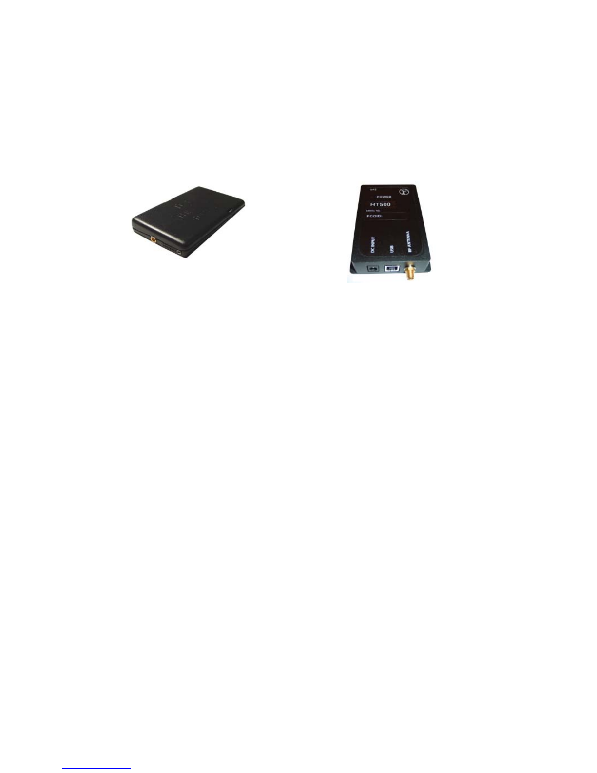
This manual covers the confi guration and operation of the HT550 Javelin remote unit (Figure 1.1.0) and
HT500 Radio Base Station (Figure 1.1.1). The HT550 Javelin is a covert GPS tracking device which
communicates via a 2.4 Ghz Spread Spectrum link over short to medium ranges. Special attention has been
paid to ensure that the HT550 Javelin is as small as possible, allowing body worn use. Real time tracking of
multiple Javelin devices is possible, as well as other operational modes covered in this manual.
Figure 1.1.0
Figure 1.1.1
The HT500 Base Station works in conjunction with the HT550 Javelin remote unit to provide users with an
extremely fl exible tracking kit. The manner in which the 2 devices communicate is based on Communication
Groups that are setup and managed in the Confi guration Database. Proper set up and usage of these
Communication Groups is what allows various Base Stations and remote units to communicate. Please see
Chapter 6 for more detailed information on setting up the Confi guration Database.
The HT550 Javelin remote unit has 3 modes of operation: Low-Power Real Time, Real-Time and User
Initiated.
Low-Power Real-Time
If confi gured to operate in this mode, the radio transmitter is turned off between fi xes to prolong battery life.
In addition, the GPS receiver is turned off between fi xes if an external GPS antenna is connected.
Real-Time
Orion has implemented an innovative real time methodology to ensure that the Javelin only sends pertinent
information when operating in a Real Time Mode. GPS fi xes are taken, stored and sent based on several
user defi nable parameters. Default values for the following parameters are used if no specifi c values are
programmed by the user.
GPS fi xes are recorded whenever:
• a specifi ed time out is reached
• a certain distance has been travelled
• the remote’s bearing has changed by a certain angle
User-Initiated
The HT550 Javelin can be confi gured to record and transmit a GPS fi x when a specifi c input switch is
triggered.
075-2000-30 rev 1.5 Orion Electronics Limited 3
Page 4

Chapter 1 Introduction
1.2 System Requirements
The following are the computer system requirements for the Orion HT550 Javelin Control Program.
Computer Requirements
In order to use the GPS equipment, and, in particular, this software, a computer is a necessity. The computer
is used to retrieve information from the hardware, program the hardware, and perform data analysis on the
resulting data. Ensure that the computer on which software will be installed meets these minimum system
requirements:
Processor: Pentium 650Mhz or better. (Queries will run faster on better CPUs)
RAM: 256 MB (or more)
Hard Drive: At least 40 MB free space (more required for saving maps to hard drive)
Disk Drive: CD ROM drive
Operating System: Windows 2000, Windows XP
Accessories: Mouse, keyboard, monitor, USB Port
Recommended system requirements:
Processor: Pentium 1Ghz or better. (Queries will run faster on better CPUs)
RAM: 512 MB (or more)
Hard Drive: At least 100 MB+ free space (more required for saving maps to hard drive)
OpenGL Graphics Card (for ArcGIS 3D Analyst)
Adding more RAM, a faster processor, and additional hard drive space will increase the speed of moving
about on the maps as well as processing the data.
4 Orion Electronics Limited 075-2000-30 rev 1.5
Page 5

Chapter 1 Introduction
1.3 Orion Contact Information
Orion Electronics Limited has been designing and manufacturing innovative electronics products since 1975.
An early beginning in products for pollution control in marine environments gradually led to an emphasis in law
enforcement products. All current product lines have been designed specifi cally for covert law enforcement use
and are sold to qualifi ed law enforcement agencies only. Our extensive warranty program, loss insurance, and
responsive technical support serve to insure any Orion purchase.
Mailing Address: Orion Electronics Limited
PO Box 2728
Windsor, NS, Canada
B0N 2T0
Ship to Address: Orion Electronics Limited
90 Sanford Dr.
Windsor-West Hants Industrial Park
Windsor, NS, Canada
B0N 2T0
Phone: 1 800 NO LIMIT (1-800-665-4648) or call (902) 798-8999 locally
(902) 790-0506 After Hours Tech Support Hotline
Fax: (902) 798-8188
Key Contacts: Call 1-800-NO-LIMIT (1-800-665-4648)
Sales Manager ext. 303
Production Manager ext. 312
Technical Support ext. 325 (during regular business hours)
Export Coordinator ext. 321
Web Site: www.orion.ns.ca
E-Mail Addresses: Sales sales1@orion.ns.ca
Production production@orion.ns.ca
R/D rd@orion.ns.ca
Tech Support skytracksupport@orion.ns.ca
075-2000-30 rev 1.5 Orion Electronics Limited 5
Page 6

Chapter 1 Introduction
1.4 Limit to Liability
To the maximum extent permitted by law, in no event shall Orion or any other party involved in the creation,
production, delivery , or licensing of the Orion product be liable to the customer or any other third party for any
incidental, indirect, special or consequential damages, or any other damages whatsoever arising from the use or
inability to use this Orion product, whether or not the possibility or cause of such damages was known to Orion,
in no event shall Orion’s liability in connection with the Orion product exceed the license fee paid for the Orion
product. This includes without limitation damages for loss of equipment or life, delays, loss of information, or
other pecuniary loss.
Orion has made an effort to check the contents of this document, incorporating information available at the
date of preparation; however, it assumes no responsibility for errors beyond its control, nor for contingent
or subsequent damages. Similarly, Orion practices a policy of continual self-improvement; we always try to
incorporate any signifi cant changes into the documentation, but there may sometimes be a delay between
product changes and documentation changes. If you have any concerns, please contact Orion or its agent.
© 1999, 2000, 2001, 2002, 2003, 2004, 2005, 2006 by Orion Electronics Limited. All rights reserved.
Written and produced by:
Orion Publications Dept.
PO Box 2728
Windsor, NS, Canada
B0N 2T0
[Ph] 1-800-NO-LIMIT
[Fax] 902-798-8188
1.5 Regulatory Information
This device complies with Part 15 of the FCC Rules. Operation is subject to the following two conditions:
(1) This device may not cause harmful interference, and
(2) this device must accept any interference received, including interference that may cause undesired
operation.
Changes or modifi cations not expressly approved by the party responsible for compliance to FCC Rules could
void the user’s authority to operate the equipment.
To reduce potential radio interference to other users, the antenna type and its gain should be so chosen that the
equivalent isotropically radiated power (EIRP) is not more than that required for successful communication.
Contact Orion Electronics’ Director of Research and Development for information on radiofrequency (RF)
exposure and regulatory compliance.
Mailing Address: Director of R&D
Orion Electronics Limited
PO Box 2728
Windsor, NS, Canada
B0N 2T0
Phone: 902-798-8999
6 Orion Electronics Limited 075-2000-30 rev 1.5
Page 7

Chapter 2 Checking the Shipment
2.1 Instructions for Warranty Coverage
After confi rming that all components were received, fi ll out the warranty card located in Appendix IX of this
manual. Be sure to include any serial numbers. Then, fax it back to Orion at
1-902-798-8188.
The warranty goes into effect upon receipt of the completed Warranty Card. If the Warranty Card has not been
received, the product is not under warranty.
2.2 Missing or Damaged Equipment
If there are missing or damaged components in either the software or hardware kits, please notify Orion
immediately at 1800-665-4648. Ask for the Export Coordinator at ext 321. Be prepared to provide the
coordinator with the following information:
• Your name, agency, address and phone number.
• The name of the carrier from which the equipment was received. Also, the name of the
individual who signed for the equipment.
• Was the box damaged?
• A list of the missing or damaged equipment including a full description of any damage
.
075-2000-30 rev 1.5 Orion Electronics Limited 7
Page 8
Chapter 3 Software Installation
3.1 Installation
Note: Please ensure SkyTrack NA / SkyTrack NA Pro has been installed on the computer before
installing the Orion Tracking Controls (OTC) CD.
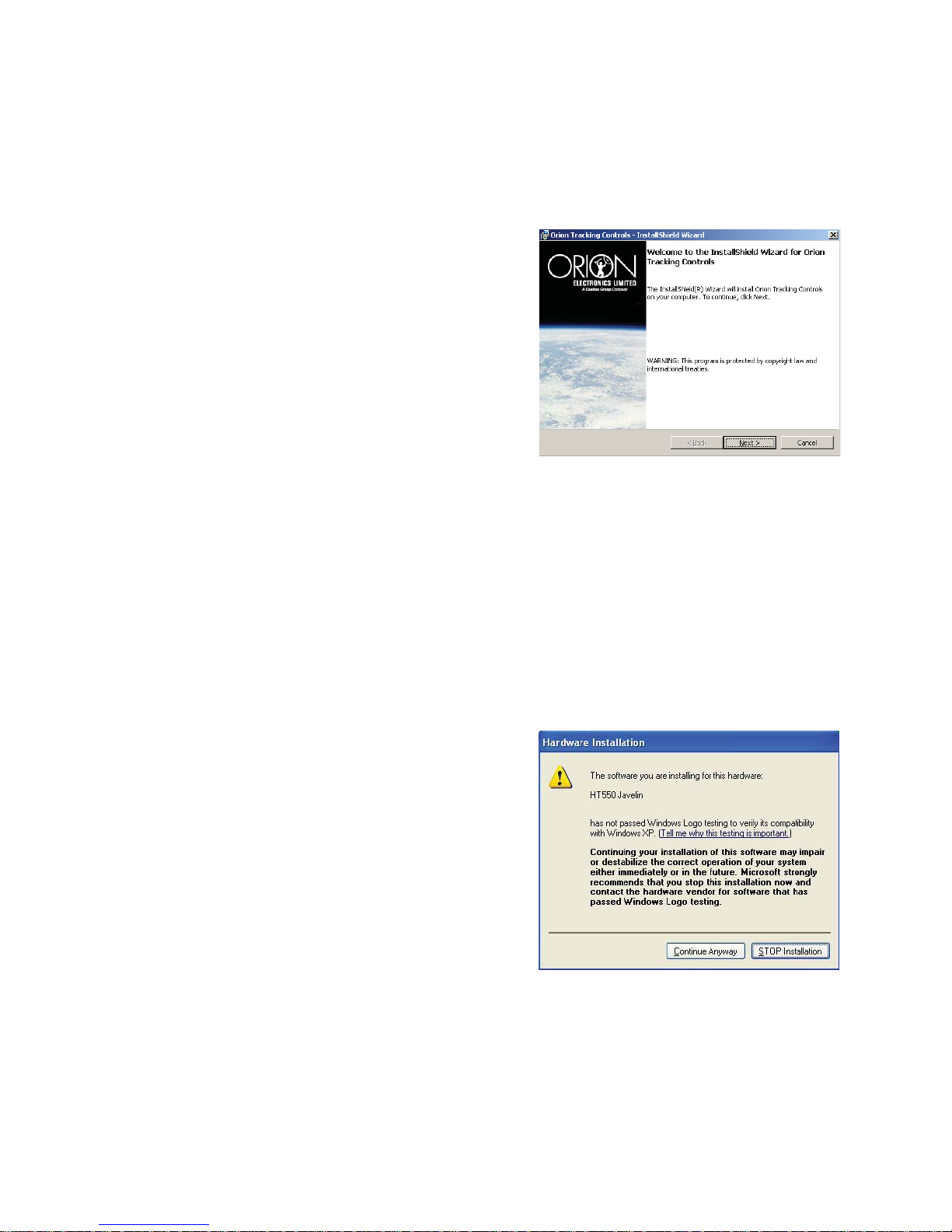
1. Insert the Orion Tracking Controls (OTC) CD into
the CD-ROM drive.
2. The Installer automatically launches the InstallShield
Wizard (Figure 3.1.0).
Users will be guided through the installation process in a
detailed, step-by-step method.
During setup, a third-party installer will run which will copy
drivers to the computer. These drivers will be detected and
installed when connecting the HT550 to the computer for the
fi rst time, follow the on-screen instructions. When setup has
been completed successfully, users may use their new Orion Controls under the chosen Orion-compatible
mapping program.
Figure 3.1.0
A copy of the Orion Control Program will be saved under the existing default directory in the hard drive. Open
the chosen mapping program to launch the Orion Control Program.
Refer to the appropriate software manual for more detailed installation instructions for the Orion-compatible
mapping software.
Installing the HT550 Javelin Tracking Control will install third-party drivers which allow the computer to
communicate with the HT550 Javelin using a USB cable.
When installing the third-party driver on a machine running
Windows XP windows may display a Windows Logo Testing
dialog. (Figure 3.1.1)
Windows XP keeps a registry of all “Microsoft Certifi ed” drivers,
and provides a warning during any installation of an uncertifi ed
driver. This warning has nothing to do with the quality of the
driver or its ability to function properly in your system. If any
changes - even minor ones - are made to a Microsoft Certifi ed
driver, that driver must go through the Microsoft Certifi cation
process again, which can take some time. The warning screen
appears when the driver update has not yet made its way through
the entire Certifi cation process.
Figure 3.1.1
However, just because a driver is unsigned does not mean that it will not function properly in your system.
Unlike previous versions of Windows, Windows XP warns users every time they try to install a driver that
Microsoft has not certifi ed.
If you see this warning during the installation, simply tell Windows that you want to Continue Anyway and
install the driver through the standard installation process.
8 Orion Electronics Limited 075-2000-30 rev 1.5
Page 9
Chapter 4 Hardware
4.1 Kit Contents
The HT550 Javelin Tracking Kit contains the HT550 Javelin unit and accessories to aid installation. The
Tracking Kit should contain the following:
HT550 Javelin Tracking Kit: HT550TDK
One (1) HT550 Javelin RF Remote Unit
One (1) HT500 RBS RF Tracker Base Station
One (1) HT500 RBS Remote Battery Charger Assembly
One (1) HT550 Base Station Cigarette Adapter
One (1) ANT-STRIP 2.4GHz Antenna
One (1) ANT-TRM2-10 ft. GPS Antenna
One (1) ANT-TRM5 GPS Antenna
One (1) 90
One (1) HT550-CIU Computer Interface Cable
One (1) HT550-RS Remote Switch
One (1) HT550BP Battery Pack
One (1) 6’ Black USB Cable
One (1) 12v AC Wall Adapter
One (1) Orion Tracking Controls Software CD
One (1) HT550 Hardware and HASP Manual
One (1) Pelican Case
o
Adjustable Knuckle Antenna
4.2 Hardware
The following section identifi es and describes the various pieces of equipment that accompany the HT550
Javelin Tracking Kit.
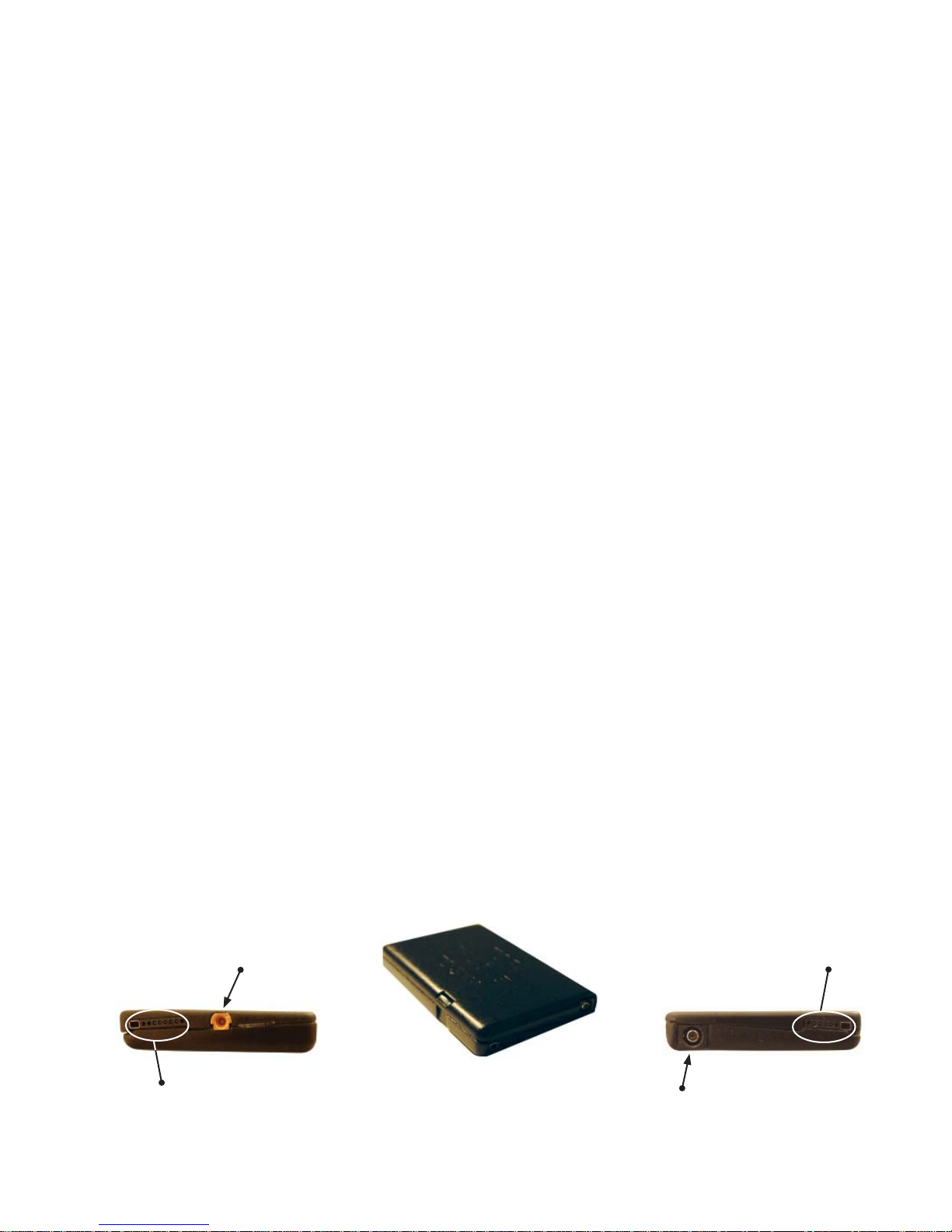
HT550 Javelin Unit
The HT550 Javelin unit is shown in Figure 4.2.0. The unit measures approximately 1.56” x 1.1” x 0.41”
without connectors or tabs and the GPS Antenna utilizes an outside ‘snap-on’ style (MMCX) connector. The
four (4) pin contains the input switch connector and the fi ve (5) pin contains the connection for the computer
interface cable and the battery pack.
MMCX External
GPS Connector
5-Pin USB Power or
Battery Connection
External RF Antenna
Figure 4.2.0
4-Pin Input
Connector
075-2000-30 rev 1.5 Orion Electronics Limited 9
Page 10
Chapter 4 Hardware
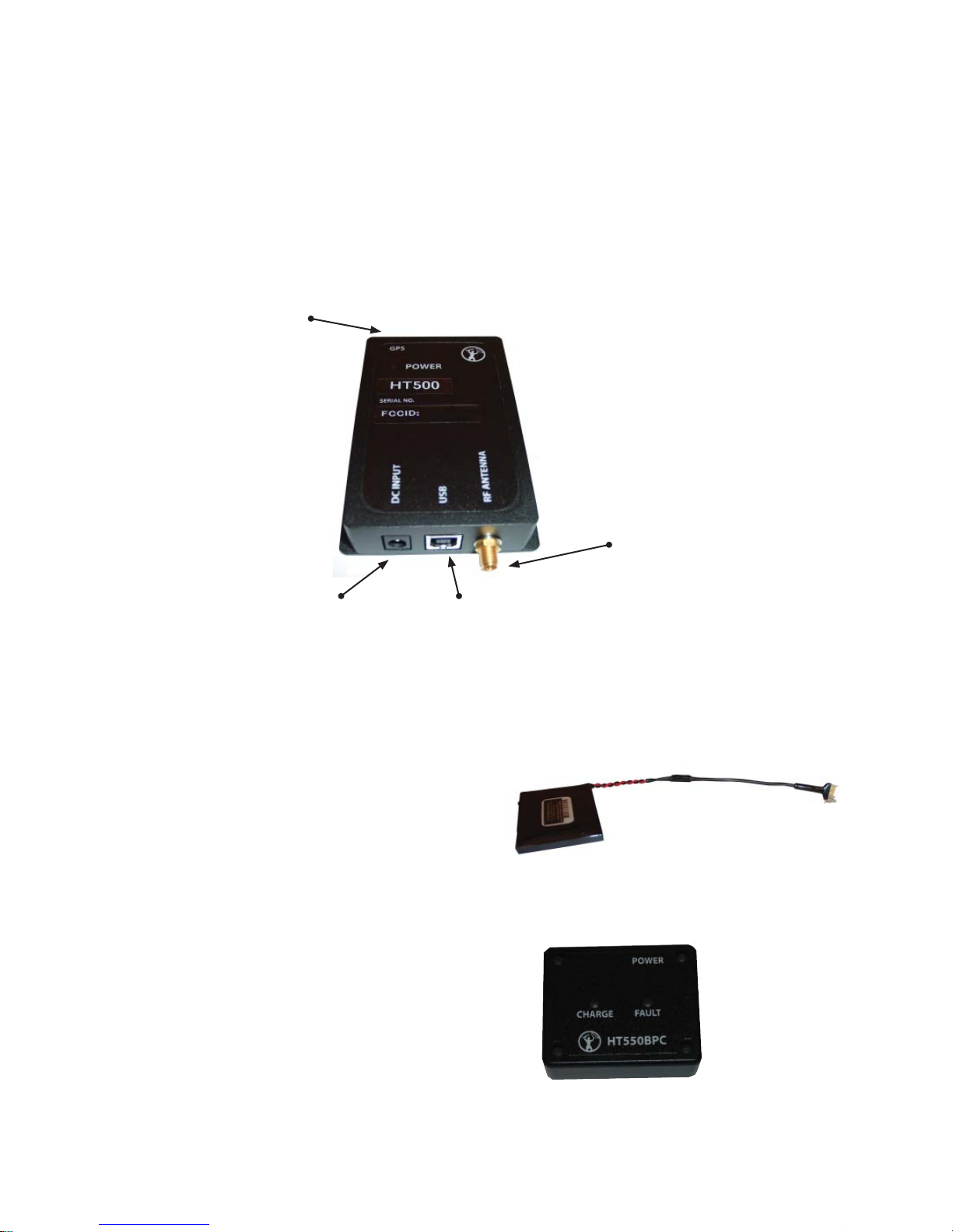
HT500 RBS RF Tracker Base Station
Figure 4.2.1 shows the RF Tracker Base Station that works in conjunction with the HT550 Javelin unit.
Please refer to Chapter 6 of this manual for detailed information on using the RF Tracker Base Station.
(NOTE: The GPS Antenna Connection is currently not functional and is intended to provide added
functionality in later product releases.)
GPS Antenna Connection
RF Antenna Connection
DC Input
USB Cable Connection
Figure 4.2.1
HT550 Battery Pack
The HT550 Battery Pack (Figure 4.2.2) is a 3.7 volt
Rechargeable Lithium Battery pack for use with the
HT550 Javelin device. Battery capacity is 1.8 Ah at 3.7
volts.
HT550 Battery Pack Charger
The HT550 Battery Pack Charger (Figure 4.2.3) is used
to recharge the HT550BP. Power to the charger is supplied
via the supplied wall adapter.
Figure 4.2.2
10 Orion Electronics Limited 075-2000-30 rev 1.5
Figure 4.2.3
Page 11

Chapter 4 Hardware
Antennas
Four antennas are shipped with the HT550 Javelin Deluxe Tracking Kit.
Figure 4.2.4 shows the ANT-STRIP 2.4GHz antenna for use with the HT550 Javelin Remote unit. The
antenna is omni-directional, but should be located as high as possible to ensure maximum range.
Figure 4.2.4
Figure 4.2.4 shows the ANT-TRM2-10 ft. GPS antenna. The ANT-TRM2-10 is for use with the HT500
RBS. (GPS functionality in the HT500 RBS is not currently enabled, but will be added in future fi rmware
releases of the Javelin system.
Figure 4.2.5
Figure 4.2.5 shows the ANT-TRM5 GPS antenna designed for use with the HT550 Javelin remote unit.
Antenna should be located as high as possible, with the best possible “view” of the sky for optimum results.
Figure 4.2.6
o
Figure 4.2.6 shows the 90
Important: The HT500 RBS must be mounted in
such a way that a separation distance of 20 cm (8”)
is maintained between the antenna and the bodies of
nearby persons.
adjustable knuckle antenna designed for use with the HT500RBS.
075-2000-30 rev 1.5 Orion Electronics Limited 11
Figure 4.2.7
Page 12

Chapter 4 Hardware
Computer Interface Cable
Programming of the HT550 requires a Computer Interface Unit (Figure 4.2.7) which is used to connect the
HT550 unit to a computer. Connection details can be found in Chapter 5 “Computer Connection”.
Figure 4.2.7
Remote Input Switch
The Remote Input Switch (Figure 4.2.8) can be used to acquire a GPS fi x, or to power up or down the GPS
receiver and/or RF transceiver. The remote input switch connects to the HT550 Javelin via a 4 pin Omnetics
connector.
Figure 4.2.8
12 Volt Cigarette Adapter
The 12 volt Cigarette Adapter (Figure 4.2.9) can be used to power the HT500 RBS from a 12 volt automotive
source or power supply.
12 Orion Electronics Limited 075-2000-30 rev 1.5
Figure 4.2.9
Page 13

Chapter 5 Confi guration Database
Note: The purpose and confi guration of individual HT550 Javelin and HT500 Radio Base Station
(RBS) settings is described later in this manual. Only the unit ID (found on the enclosure) is required
for the Confi guration Database.
5.1 Communication Group Introduction
HT550 Javelins and HT500 Radio Base Stations (RBS) are organized in Communication Groups. Both units
MUST be in the same group to communicate with one another.
A group allows a set of HT550 Javelins to communicate with a set of HT500 RBSs but:
• An HT550 Javelin can communicate with only one HT500 RBS at a time.
• An HT500 RBS can communicate with up to fi ve HT550 Javelins at a time.
Why would I want to confi gure multiple HT550 Javelins to work with a single HT500 RBS?
The multiple access scheme in the HT550 Javelin allows up to 5 HT550s to work with a single HT500 RBS.
This reduces the number of HT500 RBSs that need to be plugged into your computer for multi tracking
purposes.
Why would I want to confi gure multiple HT500 RBS Radio Base Stations to work with a single HT550
Javelin?
If an HT550 Javelin goes out of range of one of the HT500 RBSs in the group, it may be picked up by one of
the other HT500 RBSs to allow tracking to continue in another location. This presents interesting possibilities
for placing HT500 RBS operators at different locations as part of an advanced tracking operation. The group
database may be confi gured once with all of the HT550s and HT500 RBSs in a tracking operation, and then
the database fi le can be shared among the HT500 RBS operators who will take part in the operation. This
reduces manual data entry and eliminates potentially costly mistakes.
The Confi guration Database is the tool that allows users to combine the HT550 Javelin devices with HT500
RBS Base Stations in Groups.
Note: The HT500 Base Station and the HT550 Javelin share the same Confi guration Database.
075-2000-30 rev 1.5 Orion Electronics Limited 13
Page 14

Chapter 5 Confi guration Database
5.2 Communication Groups Tab
After the HT550 Javelin and HT500 RBS software have been installed as described in Chapter 3, the
Confi guration Database can be opened by selecting the “Confi guration” button (Figure 5.2.0) on the HT550
Javelin and HT500 RBS HASP (control program).
Figure 5.2.0
Note: The procedure for opening a HASP varies depending on the mapping application being used. If
required, refer to your DAS manual or DAS help fi le for instructions.
To create a new group select the <new> entry in the Groups dialog box (Figure 5.2.1).
Figure 5.2.1
Enter a suitable Group name in the Group Name fi eld. The Group Identifi er is an 8 digit hexadecimal
(base 16) number. Each digit in a hexadecimal number is one of the numerals 0-9 or letters A-F. Codes can
be edited to having HT550 Javelins or HT500 RBS devices assigned to the group by selecting the Edit ID
button.
Note: Editing these codes is not recommended unless necessary.
Once the Group Name and Group Identifi er have been determined select the Add Group button to create the
new Group.
14 Orion Electronics Limited 075-2000-30 rev 1.5
Page 15

Chapter 5 Confi guration Database
5.3 Javelin Units Tab
The Javelin Units T ab (Figure 5.3.0) is used to add HT550 Javelins to the Confi guration Database so they
can be added to Communication Groups.
Figure 5.3.0
Figure 5.3.1 displays the Javelin Units portion of the Confi guration Database. Use this window to add
Javelin units to the database so that they may be confi gured to communicate with certain Base Stations.
Figure 5.3.1
Javelin units are added to the database the same way Communication Groups are added; by simply selecting
<new> in the Javelins column to the left, and then typing an ID in the HT550 Remote Unit ID fi eld. (The
Javelin ID is always the Serial Number of the device.)
Assigned to Group
After the new Javelin unit has been added, users will need to assign the unit to a group. In the
Communications Group section, select the down arrow next to Assigned to Group. All the groups that
were set up in the Communication Groups dialog will appear in this drop down list. Select the group that the
Javelin is to belong to.
Display Characteristics
The Display Characteristics section of the Javelin units dialog allows users to name the Javelin device and
select an icon for use during real time tracking. Names must be no longer then 12 alpha numeric characters.
The Symbol and Color dialog allows users to choose exactly how the target will appear in the mapping
software. Scroll down either list to make the desired selections, and select OK when complete. A sample of
the target chosen will show to the right of the dialog (Figure 5.3.2).
Figure 5.3.2
Once the unit details have been entered, select the Commit Changes button to apply the settings. If the
device in question is not currently connected to the computer, the changes will be applied the next time the
Javelin unit is connected.
075-2000-30 rev 1.5 Orion Electronics Limited 15
Page 16

Chapter 5 Confi guration Database
5.4 Base Stations Tab
The Base Stations Tab (Figure 5.4.0) is used to add HT500 Base Stations to the Confi guration Database so
they can be added to Communication Groups.
Figure 5.4.0
Base Stations are added to the database the same way Communication Groups and Javelin units are added; by
simply selecting <new> in the Base Stations column to the left, and then typing an ID in the HT500 Radio
Base Station fi eld.
Note: Base Stations will only communicate with Javelin units that are assigned to the same group and
loaded in the Base Station Use the Remotes in Group and Remotes in Base area to view the Javelin
units assigned to the same group and load them into the Base Station. Please see Section 6.3 for more
detailed information on the Confi guration Database.
Users must select Commit Changes for the changes to be applied to the Base Station.
Import Database: It is possible to import other databases that include various Javelin devices, HT500 RBS
devices and pre confi gured groups. This is especially useful when transferring Group information to other
operators of HT500 RBS devices.
Note: After selecting the fi le to import, a warning dialog will display: “The Database import will add new
information to the database but will not overwrite any existing settings.” The import function appends the
information that is different, but doesn’t change anything already in the settings.
Export Database: It is possible to export the database that includes various Javelin devices, HT500 RBS
devices and pre confi gured Groups. This is especially useful when transferring Group information to other
operators of HT500 RBS devices.
Close: The Close button will close the Confi guration Database window and the HASP from which it was
opened will be displayed.
16 Orion Electronics Limited 075-2000-30 rev 1.5
Page 17

Chapter 6 HT550 Javelin Confi guration
Note: The fi rst time an HT550 Javelin or HT500 Base Station is connected to a particular computer the
Found New Hardware Wizard will run. For the option “Connect to Windows Update?”, select “No, not
this time”.
6.1 HT550 Javelin Direct Connection
The HT550 Javelin is confi gured and records can be downloaded through direct connection to a computer with
the software installed (see Chapter 3 for software installation instructions). The unit can be connected directly
with the Computer Interface Cable via an available USB port.
Complete the following steps to connect the HT550 Javelin directly to a computer:
1. Plug the 5-pin Omnetics connector of the Computer Interface cable into the HT550 Javelin.
2. Plug the USB into an available USB port on the computer.
3. When an HT550 HASP is loaded the software will automatically recognize any connected HT550’s.
Multiple HT550 Javelin devices can be connected concurrently.
6.2 HT550 Javelin HASP
Once the HT550 HASP has been loaded the HT550 HASP dialog (Figure 6.2.0) will be displayed. The
HT550 HASP dialog displays all available information on any connected HT550 Javelin devices.
Figure 6.2.0
Select Remote Unit: Use the drop down menu to change the currently viewed device to another. Javelin
device names are the serial number of the connected device. (Because the HT550 connects via USB it is
possible to have multiple HT550 devices connected concurrently.)
Member of Group: Displays the group that the HT550 is currently assigned to. For more information on
Groups please refer to section 6.3.
Last Record Downloaded: Indicates the last record number downloaded.
Total Records: Indicates the number of records currently stored in memory.
Firmware Revision: Indicates the Firmware Revision number of the HT550 device. (Important information
for technical support.)
Download Records: Use the Download Records button to download stored records from the connected
Javelin device.
075-2000-30 rev 1.5 Orion Electronics Limited 17
Page 18

Chapter 6 HT550 Javelin Confi guration
The Download Records dialog (Figure 6.2.1) shows the last record downloaded and the total number of
records currently stored in memory. The dialog will automatically start at the last record downloaded, though
users may select the range of records to be downloaded. Range must correspond to the number of records in
memory.
Figure 6.2.1
Clear Memory: Use the Clear memory button to clear all records from the Javelin’s memory. A warning
dialog (Figure 6.2.2) is displayed to prevent accidental clearing of memory. Records can not be retrieved
once they are cleared.
Figure 6.2.2
6.3 Unit Settings
Use the Unit Settings button to bring up the Settings dialog (Figure 6.3.0) for the current Javelin device.
Figure 6.3.0
6.3.1 Group Confi guration
Assigned to Group: This dialog displays the current group assignment for the Javelin device. Group
Assignment can be changed using the drop down menu. For more information on Group Assignment please
refer to section 6.3.
Group ID: Displays the Group Identifi cation code for the selected group. This fi eld cannot be changed within
the Javelin Unit Settings dialog.
18 Orion Electronics Limited 075-2000-30 rev 1.5
Page 19

Chapter 6 HT550 Javelin Confi guration
6.3.2 GPS Settings
The HT550 Javelin has 3 different modes of operation: Real Time, Low Power Real Time, and User
Initiated.
1. Real Time
The Javelin records and transmits fi xes based on changes in speed, position and bearing as well as regular
intervals if the unit is not in motion. To confi gure the parameters for Real Time Mode select the Advanced
Settings button within the GPS Settings dialog.
Advanced Settings (Figure 6.3.1)
Default Real Time Fix Interval: This number defi nes how often the
Javelin will record and transmit a GPS fi x when neither the Maximum
Distance or Maximum Bearing are exceeded. Minimum value is 1 second
and maximum value is 120 seconds. (Default setting is 30 seconds)
Maximum Distance Between Fixes: Select the maximum distance the device can travel before it records
and transmits a GPS fi x. Minimum value is 1 meter, maximum value is 1 kilometer. (Default setting is 15
meters)
Maximum Bearing Change: Select the number of degrees in bearing change by the device to have the
Javelin record and transmit a GPS fi x. Minimum value is 2 degrees and the maximum value is 180 degrees.
(Default setting is 7 degrees)
Figure 6.3.1
2. Low Power Real Time
The unit records and transmits fi xes at the specifi ed time interval. If an external GPS antenna is connected the
GPS receiver will power down between fi xes. The maximum time interval is 24 hours and the minimum is 2
minutes. Enter the desired time interval in the Interval dialog boxes (Figure 6.3.2).
Figure 6.3.2
3. User Initiated
In user initiated mode ( Figure 6.3.3) the unit records and transmits fi xes when the user triggers the input
switch. If an external GPS antenna is connected the GPS receiver will power down between fi xes.
Figure 6.3.3
075-2000-30 rev 1.5 Orion Electronics Limited 19
Page 20

Chapter 6 HT550 Javelin Confi guration
6.3.3 Input Settings
The HT550 Javelin is able to perform various actions based upon input triggers. Users are able to trigger the
input of the Javelin using the supplied input switch.
NOTE: Input settings are disabled when the Javelin is confi gured to operate in User Initiated Mode.
Initiate GPS Fix: Upon sensing the input trigger the Javelin will acquire a GPS fi x and transmit it to the Base
Station.
Radio Power: Upon sensing the input trigger the Javelin will power down (or up) the remote’s
communication transceiver, making remote detection diffi cult.
Radio and GPS power: Upon sensing the input trigger, the Javelin will power down (or up) the remote’s
communication transceiver and GPS receiver making remote detection very diffi cult.
Send Alarm: Upon sensing the input trigger the Javelin will set (or un-set) the alarm mode on the remote.
When in alarm mode the Javelin records and transmits GPS fi xes at 1 second intervals.
6.3.4 Apply Changes
Once all parameters have been programmed in the Unit Settings dialog, select Apply Changes to have the
settings applied to the current Javelin device. If settings have been changed but not applied, a red label will
appear between the Help button and the Unit Settings button stating “SETTINGS CHANGED”.
6.4 Help
Users can select the Help button to access the online help fi le.
20 Orion Electronics Limited 075-2000-30 rev 1.5
Page 21

Chapter 7 HT500 Radio Base Station Confi guration
Note: The fi rst time an HT550 Javelin or HT500 Base Station is connected to a particular computer the
Found New Hardware Wizard will run. For the option “Connect to Windows Update?”, select “No, not
this time”.
7.1 HT500 Base Station Direct Connection
The HT500 RBS connects to the computer using the supplied USB cable to any available USB port. Mulitple
HT500 RBS’s can be connect concurrently.
Complete the following steps to connect the HT500 Base Station directly to a computer:
1. Plug the USB connector into the HT500 RBS. The supplied USB cable has 2 USB connectors on it. The
rectangular connector end is used for the Base Station.
2. Plug the standard USB connector into an available USB port on the computer.
3. When an HT500 RBS HASP is loaded the software will automatically recognize any connected HT500’s.
Multiple HT500 RBS devices can be connected concurrently.
When the HT500 RBS HASP is fi rst opened (Figure 7.1.0) it will automatically populate with the information
from any HT500 RBS devices currently connected to the computer. Each connected base station will have its
own tab, with the serial number displayed.
Figure 7.1.0
Select a group from the Group drop down menu to access all associated Javelin devices. To add additional
HT550 Javelin devices to the group use the Confi guration button as described in section 6.3.
Tracking
To begin real time tracking of the Javelin remote units, select the devices from the Remotes in Group dialog
and use the arrow keys to move them into the Remotes in Base. Once all the desired remotes are added to the
Remotes in base dialog, select the Start button to begin tracking.
075-2000-30 rev 1.5 Orion Electronics Limited 21
Page 22

Chapter 7 HT500 Radio Base Station Confi guration
7.2 Real Time Tracking
The Real Time tracking dialog (Figure 7.2.0) displays all requested information for up to fi ve (5) connected
Javelin devices. If more then one (1) HT500 RBS is connected to the tracking computer, users can alternate
between HT500 RBS’s by using the tabs with the HT500 RBS serial number.
Figure 7.2.0
Each Javelin remote unit loaded from the Group is displayed along with its current status. Holding the mouse
cursor above any icon or fi eld will bring up a brief description of the icon or fi eld.
Map Follows this Target: Place a check mark in this fi eld to have the mapping software center on
this specifi c Javelin remote unit. Other devices will still be visible if they are within the area of the
current zoom level.
Target Symbol and Color: This icon is the shape and color icon that was chosen to represent this
device during programming of the Javelin remote device. Select this button to change the symbol
and/or color. (See Section 6.3.2)
Target Name: Displays the name of the remote unit as entered into the Confi guration database.
For the remainder of the fi elds, the user may choose to display certain preferences
Options (Figure 7.2.1, next page): Select the Options button to change the information that is displayed in
the Battery Status, Fix Information and Fix Age/Memory Status fi elds.
22 Orion Electronics Limited 075-2000-30 rev 1.5
Page 23

Chapter 7 HT500 Radio Base Station Confi guration
Options con’t: The Options dialog allows user to modify the information that is displayed within the Javelin
Status bar during real time tracking.
NOTE: Changes in the options menu are applied to all Javelin remote devices.
Figure 7.2.1
Battery Status: Users can choose to have the current input voltage that the Javelin is receiving from its
power source, or to display the current Power Consumption in mWh.
Fix Information: Users can choose to have the current speed of the target displayed, or the current direction
of the Javelin device.
Fix Age / Memory Status: Users can choose to have the time since last reported GPS fi x displayed, or the
number of records that have been received since the start of the live tracking session.
Speed Units: Users can choose to have the current speed of the target displayed in Miles per hour, or
Kilometers per hour.
Download Options: Users can choose to download all records in memory upon a download request, or to
download only the records accumulated since the last download.
Once all changes have been made, select OK to apply the changes to the display bar or select Cancel to return
to the previous screen without applying changes.
RF Signal Status: The RF Signal Status icon provides visual feedback on the current state of the
connection between the Javelin remote unit and the HT500 RBS. Green indicates a good connection,
Yellow indicates a marginal connection and Red indicates no connection.
Download: The Download records from remote unit will initiate a download from the selected unit.
Once the download has begun a progress bar will replace the status fi elds. Abort the download by
selecting the Abort Download button. Users will be prompted to save the track after the download is
complete.
075-2000-30 rev 1.5 Orion Electronics Limited 23
Page 24

Chapter 7 HT500 Radio Base Station Confi guration
Signal Remote Unit: The HT550 Javelin has an internal vibration device which can be used to
covertly notify the user. Select the Signal Remote Unit to cause the vibration device to vibrate for a 2
second pulse.
Select the Stop button to close the active connection with all connected Javelin devices. Once selected a
warning dialog (Figure 7.2.2) will appear to ensure that disconnection is intended.
Figure 7.2.2
7.3 Help
Users can select the Help button to access the online help fi le.
24 Orion Electronics Limited 075-2000-30 rev 1.5
Page 25

Appendix I HT550 Vibration Patterns
The HT550 Javelin unit is also capable of vibratory feedback. An explanation of the possible vibratory
patterns are listed and explained below.
HT550 Vibration Patterns
1. Start User Initiated Fix - 1 Second of Vibration followed by 1 second of non-vibration. Repeated 3
times.
2. Got User Initiated Fix - 4 ½ second vibrations with a ½ second pause between each vibration.
3. Start Alarm Mode – 2 Second Vibration followed by 1 second pause, followed by 2 second
vibration.
4. End Alarm mode – 2 Second Vibration, ½ second pause, 1 second vibration, ½ second pause, 2
second vibration.
5. RF OFF (RF & GPS Off) – 2 second vibration, 2 second pause, 2 second vibration.
6. RF ON (RF and GPS On) – 1 second vibration, 2 second pause, 1 second vibration.
7. Remote Signal (HASP) – 2 Second Vibration.
075-2000-30 rev 1.5 Orion Electronics Limited 25
Page 26

Appendix II Time Zone Maps
Time Zones (USA)
Daylight Saving Time
1. Not all States and Provinces participate in Daylight Savings. (e.g. Saskatchewan). Check with the
local area to see if the target’s region is also such an exception.
26 Orion Electronics Limited 075-2000-30 rev 1.5
Page 27

Appendix II Time Zone Maps
Time Zone Maps - Canada
075-2000-30 rev 1.5 Orion Electronics Limited 27
Page 28

Appendix III ESD
Electrostatic discharge or ESD is more commonly referred to as static electricity. ESD is produced by friction
between two surfaces that are in intimate contact. Some materials such as synthetics have a higher capacity than
others for holding static charges. This is especially true in dry environments. In an offi ce, something as routine
as walking over carpet or getting out of a upholstered chair can create a static charge. Electronic components
can be damaged at ESD levels not sensed by humans. Most people do not sense static charges below 4000 volts
while only a few hundred volts can damage many devices. This damage is not often catastrophic but it will
degrade the performance and life span of the device. It is important to realize that ESD damage is accumulative
and repeated exposure to ESD can result in below average performance and or product failure.
Orion Electronics Limited employs state of the art ESD controls during each stage of its manufacturing process.
This includes but is not limited to the use of static dissipative work surfaces, fl oor coverings, heel straps, and
wrist grounding straps. ESD protection has also been designed into the hardware at the circuit board level.
BEWARE:
The safeguards employed by Orion do have their limitations. ESD controls and handling procedures should be
employed when handling Orion equipment which is open with circuit boards or serial ports exposed.
Some things to avoid in order to limit ESD exposure:
1. Carpeting in the areas in which equipment is opened with circuit boards or serial ports exposed.
2. Glass surfaced work areas.
3. Areas in which individuals frequently experience static electricity shocks.
Call Orion for more information on how to deal with high-risk ESD areas at 1-800-665-4648.
28 Orion Electronics Limited 075-2000-30 rev 1.5
Page 29

Appendix IV Warranty Information
This Warranty may be subject to applicable Federal, State or Provincial Limitations and Regulations.
INSTRUCTIONS FOR WARRANTY COVERAGE
After confi rming that all components were received, fi ll out the warranty card located in Appendix V of this
manual. Be sure to include any serial numbers. Fax it back to Orion at 1-902-798-8188.
The warranty goes into effect upon receipt of the completed Warranty Card. If the Warranty Card has not been
received, the product is not under warranty.
MISSING OR DAMAGED EQUIPMENT
If there are missing or damaged components in either the software or hardware kits, please notify Orion
immediately at 1800-665-4648. Ask for the Export Coordinator at extension 321. Be prepared to provide the
coordinator with the following information:
• Your name, agency, address and phone number.
• The name of the carrier from which the equipment was received. Also, the name of the
individual who signed for the equipment.
• Was the box damaged?
• A list of the missing or damaged equipment including a full description of any damage.
TERMS OF WARRANTY
Orion Electronics Limited warrants the equipment and its components for a period of one (1) calendar year
from the date of purchase, to the original purchaser, under normal use and service, and only against defective
materials and/or workmanship. This includes Orion manufactured software. Please refer to Orion’s software
license Agreement.
Orion Electronics Limited, or it’s agents, will repair or replace any part or whole of the equipment that is
deemed defective within the terms and conditions of this warranty by the company , or its agents, during the one
(1) year warranty period. All equipment meeting the conditions of the warranty will be repaired or replaced
by like equipment on a “one for one” basis at Orion’s discretion. Future product upgrades that improve unit
performance beyond original stated specifi cations of the delivered product are not part of the original product
warranty . Orion’s liability is limited to the repair / replacement of hardware / software actually purchased from
Orion.
The equipment must be packaged so as to protect it from the rigors of shipment, and must be insured and
shipped at the customer’s cost. If found to be defective under warranty terms, it will be return shipped at Orion’ s
expense.
CONDITIONS OF WARRANTY
The Warranty will be null and void if;
• The equipment has been damaged due to improper use or installation.
• The equipment is damaged or destroyed if used in a service for which the equipment was not
advertised or designed to do.
075-2000-30 rev 1.5 Orion Electronics Limited 29
Page 30

Appendix IV Warranty Information
• If it is damaged by improper service by unauthorized personnel, or by the substitution of
improper parts or the deemed substitution of improper parts from other equipment.
• The equipment is damaged by the application of voltages higher than those specifi ed, or used with
the wrong polarity.
• The equipment is damaged by the use of chemical or other compounds used to clean it.
• The equipment is repeatedly damaged due to improper electrostatic discharge controls and
handling techniques.
Orion Electronics Limited does not authorize any person to create for it any other obligation or liability in
connection with the equipment. The responsibility of Orion Electronics Limited is limited to the warranty
herein provided, and the equipment is accepted by the customer subject to such limitation and the conditions
listed above.
LOSS / DAMAGE REPLACEMENT WARRANTY
In addition, all on - target components (meaning those parts and accessories required for proper installation)
are covered under a separate loss / damage replacement warranty which lasts for the life of the unit. Lost,
stolen or irreparably damaged items can be replaced for 50% of current list price at the time of the incident.
30 Orion Electronics Limited 075-2000-30 rev 1.5
Page 31

Appendix V Warranty Card
a
WARRANTY
Return of this warranty ensures you are registered under our warranty program, enables you to 24 hour tech support and
Name & Title ______________________________________________ Agency Name _______________________
Full Mailing Address____________________________________________________________________________
_____________________________________________________________________________________________
Phone ___________________________ Fax ____________________________ Cell ______________________
Email ________________________________________________________________________________________
Date Equipment Received ____________________________In Good Order_______________________________
Model _______________________________________________________________________________________
Serial Numbers ________________________________________________________________________________
Please fi ll in and return within 60 days by fax to 1-902-798-8188.
allows us to notify you of product and software updates.
PLEASE FILL OUT THIS
Customer Satisfaction Survey
TO HELP US SERVE YOU BETTER
Why did you choose this particular product?
1
2
What kind of application is it being used for?
Homicides Bait Cars Arson Sexual Predators Narcotics
Paranoid Suspects Break & Enters Homeland Security Agent Protection High Value Cargo
Other (Please Specify)
3
Are there any additions or improvements you’d like to see implemented?
4
Additional comments
1-800-NO LIMIT www.orion.ns.c
075-2000-30 rev 1.5 Orion Electronics Limited 31
 Loading...