

Page 1

IN 100 Rev. A 0998
Providing Exceptional Consumer Optical Products Since 1975
Customer Support (800) 676-1343
E-mail: support@telescope.com
Corporate Offices (831) 763-7000
P.O. Box 1815, Santa Cruz, CA 95061
INSTRUCTION MANUAL
Orion
®
Equatorial Mount
#9233 With Hardwood Tripod
Page 2
2
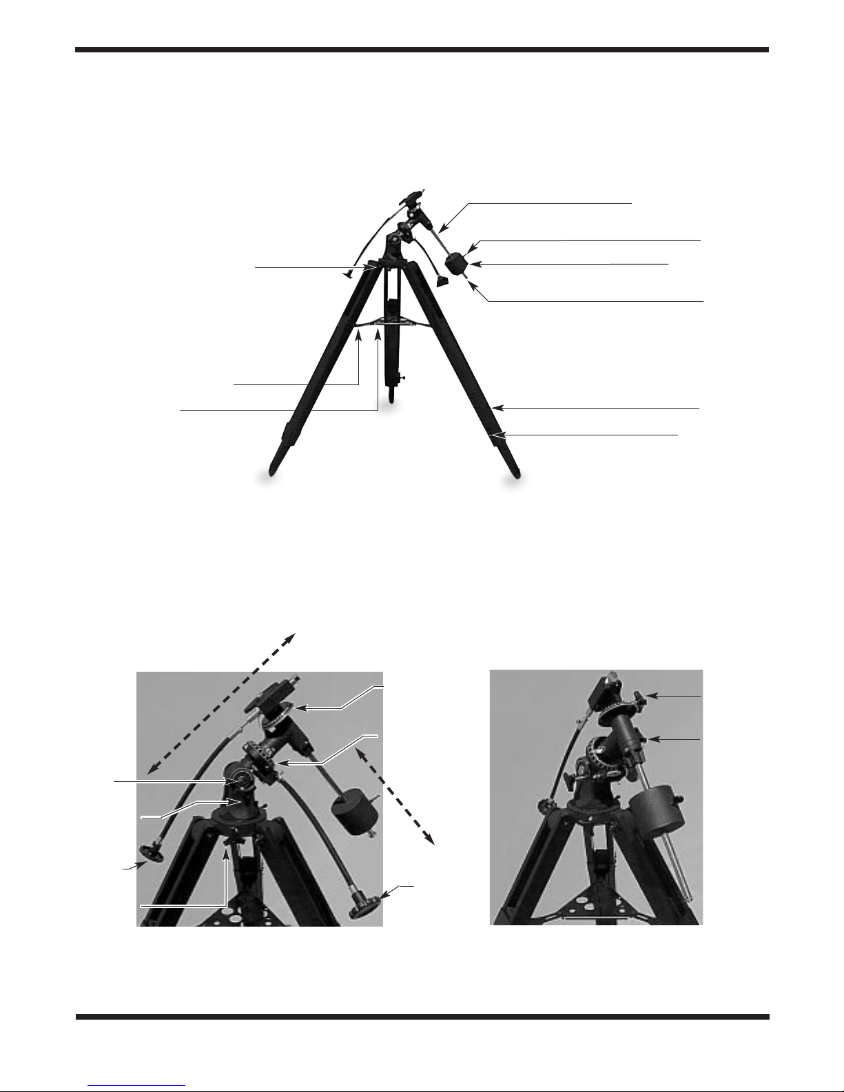
Figure 2. EQ Mount Close-Up Diagrams
Counterweight shaft
Counterweight
lock knob
Counterweight
Retaining washer
and knob
Tripod leg
Leg lock bolt
Tripod leg attachment bolt
Accessory tray bracket
Accessory tray
Dec. setting
circle
R.A. setting
circle
Right ascension
slow-motion
control
Latitude
scale
Latitude
lock knob
Dec. slowmotion
control
Azimuth
lock knob
Declination
lock knob
Right ascension
lock knob
DECLINATION AXIS
RIGHT ASCENSION (POLAR) AXIS
Figure 1. EQ Mount Parts Diagram
Page 3

3
1. Parts List
Qty. Description
1 German-type equatorial mount
2 Slow-motion control cables
1 Counterweight
1 Counterweight shaft
3 Tripod legs
1 Tripod accessory tray
2 Accessory tray screws and wing nuts
1 Crescent wrench (1/2")
2. Assembly
Carefully open all of the boxes in the shipping container.
(Some of the boxes will be empty;they are included for packing.) Make sure all the parts listed in section 1 are present.
Save the boxes and packaging material. In the unlikely event
that you need to return the equatorial mount during the warranty period, you must use the original packaging.
Assembling the mount for the first time should take only about
10 minutes.All knobs and nuts should be tightened securely to
eliminate flexing and wobbling, but only tighten them
“finger tight.” Be careful not to over-tighten so as not to strip the
threads.Refer to Figures 1 and 2 during the assemb ly process.
1. Lay the equatorial mount on its side.Attach the tripod legs
one at a time to the base of the mount by sliding the tripod
leg attachment bolt into the slot in the mount and tightening the wing nut finger-tight. Use the crescent wrench
provided to hold the hexagonal head of the bolt still while
you turn the wing nut. Note that the hinged accessory tray
bracket on each leg should face inward.
2. Extend the inner portion of each tripod leg to the same
length and then tighten the leg lock bolts to secure them
at that length.You can adjust the legs to a more desirable
length later, once the mount is fully assembled and your
telescope is in place.
3. With the tripod legs now attached to the equatorial mount,
stand the tripod upright (be careful!) and spread the legs
apart enough to attach the accessory tray to the three
hinged tray brackets on the legs. The brackets should be
positioned underneath the tray.Use the three small accessory tray screws and wing nuts provided. Do not tighten
the wing nuts yet.
4. Now, with the accessory tray attached loosely, spread the
tripod legs apart as far as they will go, until the accessory
tray brackets are taut.Then tighten the wing nuts.
5. Next, tighten the wing nuts of the tripod leg attachment
bolts at the base of the equatorial mount, so the legs are
securely fastened.
6. Slide the counterweight onto the counterweight shaft,
making sure the retaining washer and screw are in place
on the end of the shaft. They will prevent the counterweight from sliding off the shaft and possibly onto your f oot
if the counterweight lock knob should loosen!
C
ongratulations on your purchase of a quality Orion product.
Your new Orion Equatorial Mount with
Hardwood Tripod offers solid stability, mechanical precision, and the versatility to accommodate a variety of different small to medium-sized telescope tubes. It features a heavy-duty equatorial head, and
dual slow-motion cables for effortless star-tracking.The setting circles will enable you to locate objects
by their cataloged celestial coordinates.We’re sure this mount will make your observing sessions both
easy and productive.
These instructions will help you set up and properly use your equatorial mount. Please read them over
thoroughly before getting started.
Table of Contents
1. Parts List................................................................................................................................. 3
2. Assembly ................................................................................................................................ 3
3. Attaching a Telescope ............................................................................................................. 4
4. Balancing the Telescope......................................................................................................... 4
5. Using the Equatorial Mount....................................................................................................4
6. Suggested Accessories.......................................................................................................... 6
Page 4

4
7. Now, with the counterweight lock knob loose, grip the counterweight with one hand and thread the shaft into the equatorial
mount (at the base of declination axis) with the other hand as
far as it will go.P osition the counterweight about halfwa y up the
shaft and tighten the counterweight lock knob.
8. Orient the equatorial mount as it appears in Figure 1, at a
latitude of about 40°, i.e., so that the pointer on the latitude
scale is pointing to the hash mark at 40.To do this , loosen
the latitude lock knob and adjust the mount until the pointer lines up with the “40.” (You will notice there are two 40
designations on the scale. Set the pointer on the 40 such
that the letters “R.A.” printed near the R.A. setting circle
face upward, rather than downward.) Then retighten the
latitude lock knob.Also tighten the declination (Dec.) and
right ascension (R.A.) lock knobs.
9. Now attach the two slow-motion cables to the R.A.and Dec.
worm gear shafts of the equatorial mount by positioning the
setscrew on the end of the cable over the indented slot on
the worm gear shaft, then tightening the setscrew. The
equatorial mount is now set up and ready to use.
Notice that on one end of the R.A. worm gear is a knurled
metal wheel, below which is a free-swinging metal tab.Those
parts are designed for use with an older model of R.A. motor
drive that is no longer readily available. The motor dr ive we
carry (#17001) as an optional accessory for this mount does
not require these parts (in fact, they have to be removed as
part of the motor installation procedure).
3. Attaching a Telescope
The Orion Equatorial Mount is designed to hold small to midsize telescopes weighing up to about 8 lbs. For heavier
telescopes, the mount may not provide sufficient stability for
steady viewing.Any type of telescope can be mounted on the
Orion Equatorial Mount, including refractors, Newtonian
reflectors, and catadioptrics, provided a proper adapter or
tube ring(s) is available to couple the tube to the mount.
Orion carries different sizes of tube rings and a 1/4"-20
mounting adapter designed to fit this mount. See the list of
Suggested Accessories at the end of these instructions, or
check the Orion print or online catalogs for currently available
mounting accessories.
4. Balancing the Telescope
Once the telescope is attached to the equatorial mount, the
next step is to balance the telescope. Proper balance is
required to insure smooth movement of the telescope on both
axes of the equatorial mount.
If you attach your telescope with a 1/4"-20 adapter, it may not
be possible to balance the scope precisely with respect to the
declination axis, because the telescope cannot be moved
back and forth as it can when a tube ring is used. Some 1/4"20 adapters have a slot or more than one hole through which
the threaded post can be set, allowing some limited adjustment of the telescope’s position for balancing.
Assuming you will be using a tube ring, we will first balance
the telescope with respect to the R.A. axis, then the Dec.axis.
1. Keeping one hand on the telescope optical tube, loosen
the R.A. lock knob. Make sure the Dec. lock knob is tightened, for now.The telescope should now be able to rotate
freely about the R.A.axis.Rotate it until the counterweight
shaft is parallel to the ground (i.e., horizontal).
2. Now loosen the counterweight lock knob and slide the
weight along the shaft until it exactly counterbalances the
telescope.That’s the point at which the shaft remains horizontal even when you let go of the telescope with both
hands. Retighten the counterweight lock knob. The telescope is now balanced on the R.A. axis.
3. To balance the telescope on the Dec.axis, first tighten the
R.A.lock knob, with the counterweight shaft still in the horizontal position.
4. With one hand on the telescope optical tube, loosen the
Dec. lock knob. The telescope should now be able to
rotate freely about the Dec. axis. Loosen the tube ring
clamp a few turns until you can slide the telescope tube
forward and back inside the ring (this can be aided by
using a slight twisting motion on the optical tube while you
push or pull on it).Position the telescope so that it remains
horizontal when you carefully let go with both hands.This
is the balance point for the Dec.axis.Before clamping the
ring tight again, rotate the telescope so the eyepiece is at
a convenient angle f or viewing (this is not possible if using
a 1/4"-20 mounting adapter).
The telescope is now balanced on both axes.Now when you
loosen the lock knob on one or both axes and manually point
the telescope, it should move without resistance and should
not drift from where you point it.
5. Using the Equatorial Mount
When you look at the night sky, you no doubt have noticed
that the stars appear to move slowly from east to west over
time. That apparent motion is caused by the Earth’s rotation
(from west to east). An equatorial mount is designed to compensate for that motion, allowing you to easily “track” the
movement of astronomical objects, thereby keeping them
from drifting out of the telescope’s field of view while you’re
observing. This is accomplished by slowly rotating the telescope on its right ascension axis, using only the R.A.
slow-motion cable.But first the R.A.axis of the mount must be
aligned with the Earth’s rotational (polar) axis—a process
called polar alignment.
Approximate Polar Alignment
For Northern Hemisphere observers, reasonable polar alignment is achieved by pointing the mount’s R.A. axis at the
North Star, or Polaris. It lies within 1° of the north celestial
pole (NCP), which is an extension of the Earth’s rotational
axis out into space.Stars in the Northern Hemisphere appear
to revolve around Polaris.
Page 5

5
To find Polaris in the sky, look nor th and locate the patter n of
the Big Dipper (Figure 3, page 7).The two stars at the end of
the “bowl”of the Big Dipper point right to Polaris. If you do not
have a clear view of Polaris from your observing site, you will
not be able to accurately polar-align the telescope.
Observers in the Southern Hemisphere aren’t so fortunate to
have a bright star so near the south celestial pole (SCP).The
star Sigma Octantis lies about 1° from the SCP, but it is barely visible with the naked eye (magnitude 5.5).
For general visual observation, polar alignment is performed
as follows:
1. Level the equatorial mount by adjusting the length of the
three tripod legs.
2. Loosen the latitude lock knob and tilt the mount head until
the pointer on the latitude scale is set at the latitude of your
observing site. If you don’t know your latitude, consult a
geographical atlas to find it. For example, if your latitude is
50° Nor th, set the pointer to 50 (again, there are two 50s
on the scale; set the pointer to the one for which the letters
“R.A.” near the R.A. setting circle face upward, not downward). Then retighten the latitude lock knob. The latitude
setting should not have to be adjusted again unless you
move to a viewing location at a different latitude.
3. Loosen the Dec.lock knob and rotate the telescope until it
is parallel with the R.A. axis. The pointer on the Dec. setting circle should read 90°. Retighten the Dec. lock knob.
4. Lift and rotate the tripod so the telescope tube (and R.A.
axis) points roughly at Polaris. Sight along the length of
the telescope tube. If you cannot see Polaris directly from
your observing site, consult a compass and rotate the tripod so that the telescope points north.
The equatorial mount is now polar-aligned for casual observing. More accurate polar alignment is required for
astrophotography; various methods can be found in books
and manuals on astrophotography or amateur astronomy.
Note: From this point on in your observing session, you
should not make any further adjustments to the azimuth
or the latitude settings, nor should you move the tripod.
Doing so will upset the polar alignment. The telescope
should be moved only about its R.A. and Dec. axes.
Tracking Celestial Objects
When you observe a celestial object through the telescope,
you’ll see it drift slowly across the field of view. To keep it in
the field, if your equatorial mount is polar-aligned, just turn the
R.A. slow-motion control.The Dec. slow-motion control is not
needed for tracking. Objects will appear to move faster at
higher magnifications, because the field of view is narrower.
Optional Motor Drives for Automatic Tracking
An optional AC motor drive (Orion part #17001) can be
mounted on the R.A. axis of the Orion Equator ial Mount to
provide automatic, hands-free tracking—a nice convenience.
Objects will then remain stationary in the field of view without
any manual adjustment of the R.A. slow-motion control.
Understanding the Setting Circles
The setting circles on an equatorial mount enable you to
locate celestial objects by their “celestial coordinates.” Every
object resides in a specific location on the “celestial sphere.”
That location is denoted by two numbers: its right ascension
(R.A.) and declination (Dec.). In the same way, every location
on Earth can be described by its longitude and latitude. R.A.
is similar to longitude on Earth, and Dec. is similar to latitude.
The R.A.and Dec.values for celestial objects can be found in
a star atlas or star catalog.
The R.A. setting circle is scaled in hours, from 1 through 24,
with small hash marks in between representing 10-minute
increments (there are 60 minutes in 1 hour of R.A.). You’ll
notice that there are two sets of numbers and hash marks on
the R.A. setting circle. The lower set of numbers (closest to
the R.A. gear) should be used for viewing in the Northern
Hemisphere; the upper set of numbers applies to viewing in
the Southern Hemisphere.The Dec. setting circle is scaled in
degrees (there are 60 arc-minutes in 1 degree of declination).
So, the coordinates for the Orion Nebula listed in a star atlas
will look like this:
R.A. 5h 35.4m Dec. –5° 27'
That’s 5 hours and 35.4 minutes in right ascension, and –5
degrees and 27 arc-minutes in declination (the negative sign
denotes south of the celestial equator).
Before you can use the setting circles to locate objects, the
mount must be very accurately polar-aligned (the method
described above is only for approximate alignment), and the
setting circles must be calibrated.
Calibrating the Declination Setting Circle
1. Loosen the Dec. lock knob and position the telescope as
accurately as possible in declination so it is parallel to the
R.A.axis of the equatorial mount.Retighten the lock knob .
2. Rotate the Dec. setting circle until the pointer reads
exactly 90°.
Calibrating the Right Ascension Setting Circle
1. Identify a bright star near the celestial equator and look up
its coordinates in a star atlas.
2. Loosen the R.A. and Dec. lock knobs on the equatorial
mount, so the telescope optical tube can move freely.
3. Point the telescope at the bright star near the celestial
equator whose coordinates you know .This information can
be taken from any star chart. Center the star in the telescope’s field of view.Lock the R.A. and Dec. lock knobs.
4. Rotate the R.A. setting circle so the pointer indicates the
R.A. listed for that object in the star atlas.
Finding Objects With the Setting Circles
Now that both setting circles are calibrated, look up in a star
atlas the coordinates of an object you wish to view.
1. Loosen the Dec. lock knob and rotate the telescope until
the Dec. value from the star atlas matches the reading on
the Dec. setting circle. Retighten the lock knob.
Page 6

6
2. Loosen the R.A. lock knob and rotate the telescope until
the R.A. value from the star atlas matches the reading on
the R.A. setting circle. Retighten the lock knob.
Most setting circles are not accurate enough to put an object
dead-center in your finder scope’s field of view, but they’ll get
you close, assuming the equatorial mount is accurately polaraligned.
Confused About Pointing the Telescope?
Beginners occasionally experience some confusion about
how to point the telescope overhead or in other directions.In
Figure 1 the telescope is pointed north, as it would be during
polar alignment. The counterweight shaft is oriented downward.But it will not look like that when the telescope is pointed
in other directions. Let’s say you want to view an object that is
directly overhead, at the zenith.How do you do it?
One thing you DO NOT do is make any adjustment to the latitude setting.That will upset the polar alignment. Remember,
once the mount is polar-aligned, the telescope should be
moved only on the R.A. and Dec. axes. To point the scope
overhead, first loosen the R.A. lock knob and rotate the telescope on the R.A. axis until the counterweight shaft is
horizontal (parallel to the ground).Then loosen the Dec. lock
knob and rotate the telescope until it is pointing straight overhead. The counterweight shaft is still horizontal. Then
retighten both lock knobs.
Similarly, to point the telescope directly south, the counterweight shaft should again be horizontal. Then you simply
rotate the scope on the Dec. axis until it points in the south
direction.
What if you need to aim the telescope directly north, but at an
object that is nearer to the horizon than Polaris? You can’t do it
with the counterweight shaft pointing down as pictured in Figure
1. Again, you have to rotate the scope in R.A. so the counter-
weight shaft is positioned horizontally.Then rotate the scope in
Dec. so it points to where you want it near the horizon.
To point the telescope to the east or west, or in other directions, you rotate the telescope on its R.A. and Dec. axes.
Depending on the altitude of the object you want to observe,
the counterweight shaft will be oriented somewhere between
vertical and horizontal.
The key things to remember when pointing the telescope is that
a) you only move it in R.A.and Dec., not in azimuth or latitude
(altitude), and b) the counterweight and shaft will not always
appear as it does in Figure 1. In fact, it almost never will!
6. Suggested Accessories
Call our Customer Service department at (800) 447-1001 for
availability and current prices. Mention the stock numbers
indicated in the parentheses.
1/4"- 20 Adapter (#9227)
This accessory bolts to the top of the equatorial head and
provides a threaded post on which to mount a camera or telescope that utilizes a standard “quarter-twenty” thread.
Tube Mounting Rings
These quality cast-aluminum rings are hinged for easy installation of the telescope tube and are lined with felt to prevent
scratching of the telescope.Check the outer diameter of your
telescope; if it matches the inner diameter (I.D.) of the ring,
then the ring will fit. Mounting bolts included. One ring only is
needed.
Ring for 80mm Refractor (I.D. 3.5") (#7056)
Has a 1/4"-20 threaded post on top for attachment of a camera
body.
Ring for 4.5" Reflector (I.D. 5.5") (#7055)
AC Motor Drive (#17001)
This is a small electric motor that attaches to the right ascension worm gear shaft of the equatorial mount. It turns the gear
on the R.A. axis at the same rate that the Earth rotates on its
axis, thereby following, or “tracking,” the apparent motion of
the stars.Automatic tracking keeps objects from drifting out of
the field of view while you’re observing. Plugs into AC wall
outlet or AC-to-DC power inverter.
Page 7

7
To find Polaris in the night sky, look nor th and find the Big Dipper. Extend an imaginary line from the two “Pointer Stars” in
the bowl of the Big Dipper.Go about 5 times the distance between those stars and you’ll reach Polaris, which lies within 1°
of the north celestial pole (NCP).
Figure 3
Big Dipper
(in Ursa Major)
Little Dipper
(in Ursa Minor)
N.C.P.
Pointer Stars
Polaris
Cassiopeia
Page 8

Orion Telescopes & Binoculars
Post Office Box 1815, Santa Cruz, CA 95061
Customer Support Help Line (800) 676-1343 • Day or Evening
One-Year Limited Warranty
This Orion Equatorial Mount with Hardwood Tripod is warranted against defects in materials or
workmanship for a period of one year from the date of purchase. This warranty is for the
benefit of the original retail purchaser only. During this warranty period Orion Telescopes &
Binoculars will repair or replace, at Orion’s option, any warranted instrument that proves to be
defective, provided it is returned postage paid to: Orion Warranty Repair, 89 Hangar Way,
Watsonville, CA 95076. If the product is not registered, proof of purchase (such as a copy of
the original invoice) is required.
This warranty does not apply if, in Orion’s judgment, the instrument has been abused, mishandled, or modified, nor does it apply to normal wear and tear.This warranty gives y ou specific
legal rights, and you may also have other rights, which vary from state to state. For
further warranty service information, contact: Customer Service Department, Orion Telescopes
& Binoculars, P. O. Box 1815, Santa Cruz, CA 95061; (800) 676-1343.
 Loading...