

Page 1
Factory Packaged Controls
Coil Products
OE377-26-00057
(AAON Part #30916)
Dual Electronic Expansion
Valve Module Technical Guide
Page 2

Table of Contents
GENERAL INFORMATION ................................................................................................................................. 3
Overview ......................................................................................................................................................................................3
Features .......................................................................................................................................................................................4
Adjustable Setpoints.....................................................................................................................................................................4
Confi gurations ..............................................................................................................................................................................4
UNIT START-UP PROCEDURES ........................................................................................................................ 5
DIMENSIONS AND MOUNTING ........................................................................................................................ 6
INSTALLATION & WIRING ................................................................................................................................7
INPUTS/OUTPUTS ............................................................................................................................................ 8
I/O Map.........................................................................................................................................................................................8
Stand Alone Input Commands......................................................................................................................................................8
SEQUENCE OF OPERATION ............................................................................................................................. 9
Initialization...................................................................................................................................................................................9
Normal Operation .........................................................................................................................................................................9
Modulation Routine ......................................................................................................................................................................9
DIAGNOSTICS ................................................................................................................................................ 10
Alarms ........................................................................................................................................................................................10
LED Descriptions........................................................................................................................................................................10
LED SCREENS ................................................................................................................................................ 12
Navigation and Main Screens Map ............................................................................................................................................12
Protected Screens Map and Main Menu Screens ......................................................................................................................13
Status V-A/B and V-A/B Alarm Screens .....................................................................................................................................14
Force Valves Screens ................................................................................................................................................................15
Setpoint Screens ........................................................................................................................................................................16
Confi guration Screens ................................................................................................................................................................17
Diagnostic Screens ....................................................................................................................................................................18
TROUBLESHOOTING ...................................................................................................................................... 19
OE275-01 Suction Pressure Transducer Testing for R410A Refrigerant ........................................................................................ 20
Coil Temperature Sensor T esting ...............................................................................................................................................21
www.aaon.com
WattMaster Controls Inc.
8500 NW River Park Drive · Parkville, MO 64152
Toll Free Phone: 866-918-1100
PH: (816) 505-1100 · FAX: (816) 505-1101 · E-mail: mail@wattmaster.com
Visit our web site at www.orioncontrols.com
WattMaster Form : AA-EXV-TGD-01A
Copyright January 2012 WattMaster Controls, Inc.
®
is a registered trademark of AAON, Inc., Tulsa, OK.
AAON
Neither WattMaster Controls, Inc. nor AAON
responsibility for errors or omissions in this document.
This document is subject to change without notice.
®
assumes any
Page 3
Dual Electronic Expansion Valve Module
Overview
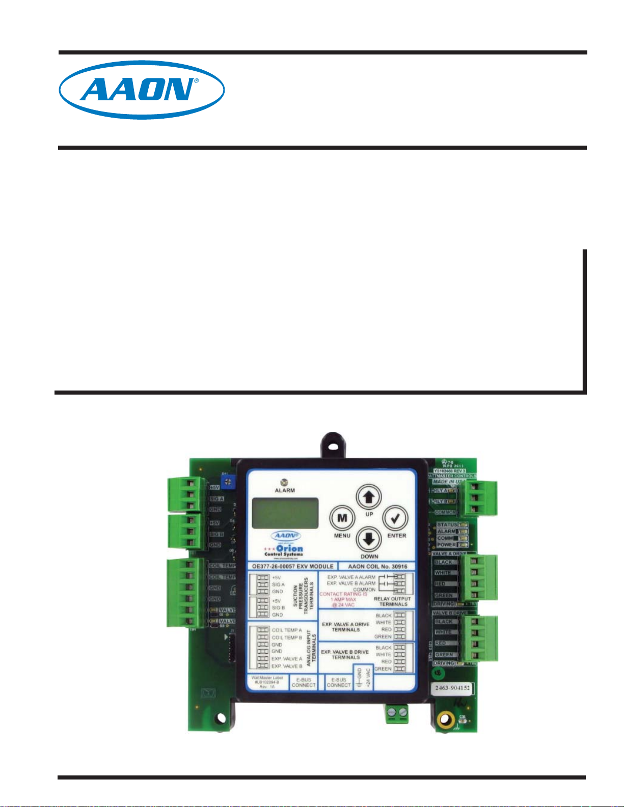
The OE377-26-00057 Dual Electronic Expansion V alve (EXV) Module
(AAON Part #30916) provides control of two electronic expansion
valves to maintain the superheat in the cooling circuits of the HVAC
unit. The module is designed only for R410-A refrigerant.
The EXV Module is used in stand-alone applications only.
General Information
YS102468 REV 3
R41
TB2
TB2
TB3
TB3
TB4
TB4
R41
+5V
+5V
SIG A
SIG A
GND
GND
+5V
+5V
SIG B
SIG B
GND
GND
COILTEMPA
COILTEMPA
COILTEMP B
COILTEMP B
GND
GND
GND
GND
VALVEA
VALVEA
D1
D1
VALVEB
VALVEB
D3
D3
D5
D5
D6
D6
D7
D7
D8
D8
GND
GND
J1
J1
YS102468 REV 3
WATTMASTER CONTROLS
WATTMASTER CONTROLS
MADE IN USA
MADE IN USA
TB1
TB1
RLYA
RLYA
RLYB
RLYB
COMMON
COMMON
STATUS
STATUS
ALARM
ALARM
COMM
COMM
POWER
POWER
VALVEADRIVE
VALVEADRIVE
BLACK
BLACK
WHITE
WHITE
RED
RED
GREEN
GREEN
DRIVING
DRIVING
VALVE B DRIVE
VALVE B DRIVE
BLACK
BLACK
WHITE
WHITE
RED
RED
C214
C214
.1uF
.1uF
GREEN
GREEN
DRIVING
DRIVING
SERIAL #
SERIAL #
C31
C31
.1uF
.1uF
TB7
TB7
TB6
TB6
Figure 1: OE377-26-00057 Dual Electronic Expansion Valve Module
Technical Guide
3
Page 4

Dual Electronic Expansion Valve Module
Features and Applications
Features
The Dual Electronic Expansion Valve Module provides the following:
• Contains a 2x8 LCD character display and 4 buttons
that allow for status display, setpoint changes, and
confi guration changes.
• Can control two electronic expansion valves independently.
• Monitors suction pressure and coil temperature and
modulates electronic expansion valves to maintain
superheat.
• Provides active relays to monitor valve alarms.
NOTE: The Dual Electronic Expansion Valve Module contains
no user-serviceable parts. Contact qualifi ed technical per-
sonnel if your Dual Electronic Expansion Valve Module
is not operating correctly.
Adjustable Setpoints
The following describes some of the setpoints available for adjustment
using the LCD display on the Dual Electronic Expansion V alve Module:
• Superheat Setpoint - One setpoint is used for
both valves.
• Modulation Rate - This setpoint (in seconds) will
adjust how often the modulation routine will make a
valve adjustment.
• Proportional Window - This setpoint (in degrees)
will adjust how much of an adjustment will be made
according to how far away it is from setpoint.
Confi guration Settings
• Board Address – Can be addressed from 1 to 4.
Used as stand-alone, the default address is 1.
• Valve B Enable – When using the module for only
one valve, valve B can be disabled so false information
is not displayed such as alarms and sensor readings.
• Valve Steps – Confi gurable for what valve is being
used (1596, 2500, 3193, 6386)
• Max Valve Position – The maximum position each
valve will modulate (%).
• Min Valve Position – The minimum position each
valve will modulate (%).
• Suction Pressure A Calibration Offset –
Adjustable between -10 and 10 PSI.
• Suction Pressure B Calibration Offset –
Adjustable between -10 and 10 PSI.
4
Technical Guide
Page 5
Dual Electronic Expansion Valve Module
AAON® Unit Start-Up Procedures
AAON® Unit Start-Up Procedures
NOTE: The following instructions were provided by AAON to set
up the unit. If you have any questions about this start-up
procedure, please contact AAON Technical Support.
Refrigeration Charging Sequence:
1. Determine valve size utilized on equipment part number from the
physical valve. There are currently 4 models used:
• SER-C (5-Ton Maximum Nominal Capacity)
• SER-D (13-Ton Maximum Nominal Capacity)
• SER-G (26-Ton Maximum Nominal Capacity)
• SER-J (48-Ton Maximum Nominal Capacity)
2. Determine circuit capacity and divide by valve Maximum
Nominal Capacity to determine average full refrigerant mass fl ow
Example: CC-B-045 Condensing unit; (2) 22.5 Ton Circuits,
Evaporator contains (2) SER-G EEV (Electronic Expansion Valve)
22.5/26 = 0.865 = 86.5%, Rounded to 87%
Fine-Tuning the EEV Module’s Setpoints for Best
Reaction Time and Effi ciency:
1. Ballpark the modulation rate based on line set length using the
following table as a guide:
Line Set Length Modulation Rate
15 15
30 20
45 30
60 35
75 40
90 45
120 50
Table 1: Modulation Rate Table
2. Ensure the outside air temperature, return air temperature, and
control setpoints do not change during calibration and fi ne-tuning
procedures.
NOTE: Consult with System Specifi cation and Unit Rating, as
lower or higher evaporator temperatures and other factors
play a role in the actual capacity the compressors may
deliver.
3. Ensure system is charged to a reasonable point to enable
compressor start and ensure that all other procedures dictated for
installation and startup have been followed from the unit IOM.
4. Set the EEV Module’s Valve to manual override position of 87%.
5. Ensure the space is fully loaded at design conditions to allow for
maximum capacity operation and lock the compressor to fullyloaded capacity.
6. Energize the compressor and ensure a solid column of liquid to the
EEV via verifi cation at the sight glass.
7. From the point of a full sight glass, follow standard charging
procedures to maximize effi ciency via sub cooling, and delta T at
the evaporator.
8. Disable the manual override position on the EEV Module and
allow automatic operation at the desired set point.
3. Power off the EEV Module completely to ensure the smart-start
routine does not skew the initial position of future tests.
4. Power on the EEV Module and initialize the unit to enable
compressor operation.
5. Monitor superheat on the EEV Module and mark the time system
started until superheat is maintained at a steady state within an
acceptable dead band for more than 60 seconds.
6. Note the time from startup to stable superheat as well as the
current modulation rate set point (this process should not take longer than 20 minutes. If it does, then check unit charge or unstable
operating conditions).
7. Adjust the modulation rate set point by 2-3 seconds in either
direction and repeat test from Step 4.
8. Compare and adjust change until the best modulation rate is
obtained for the fi nal setting.
9. Verify superheat operation and consistent solid column of liquid at
the sight glass. This may take up to 15 minutes.
10. Repeat instruction for Valve 2 starting with Step 3.
Technical Guide
5
Page 6
Dual Electronic Expansion Valve Module
Dimensions and Mounting
Environmental Requirements
The Dual Electronic Expansion Valve Module needs to be installed in
an environment that can maintain a temperature range between -30°F
and 150°F and not exceed 90% RH levels (non-condensing).
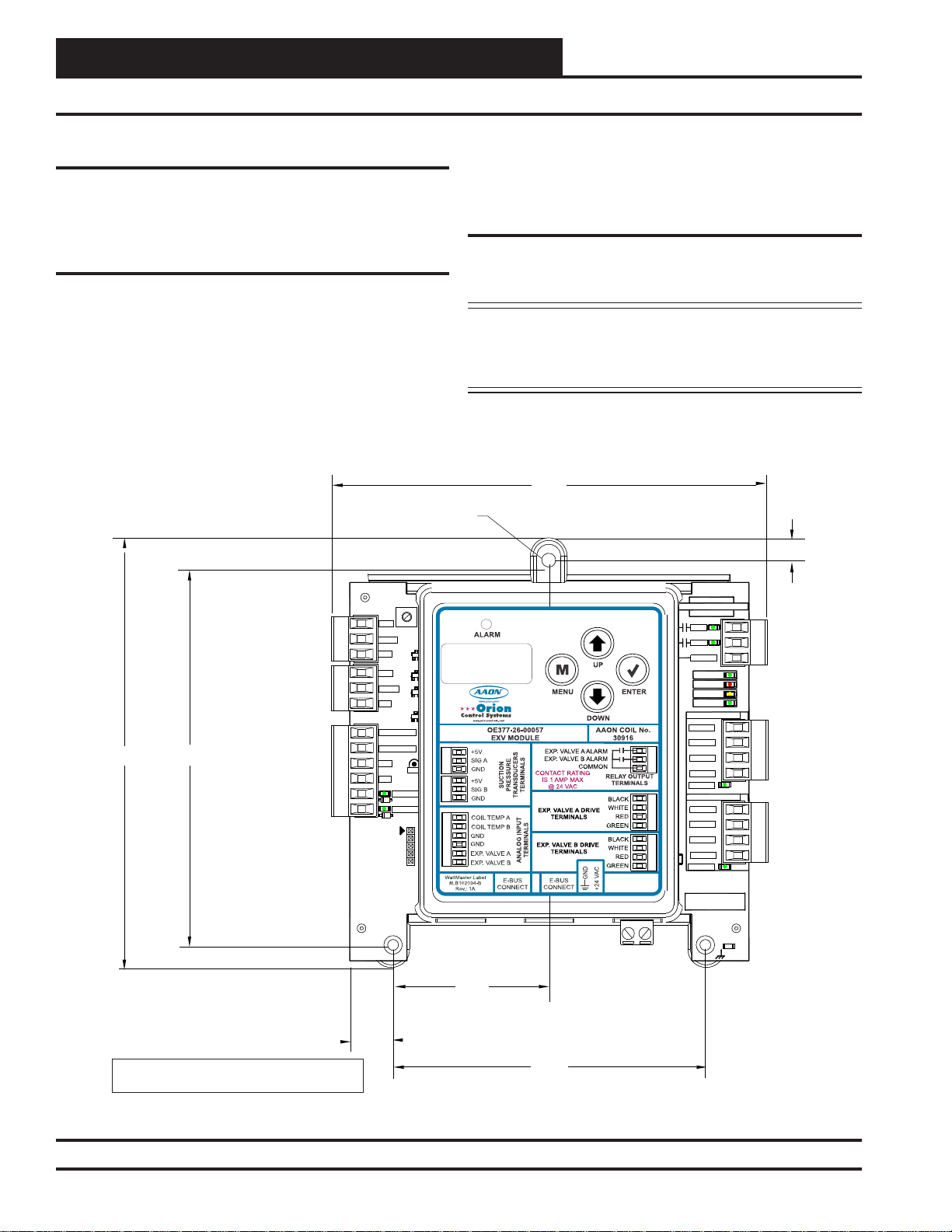
Mounting
The Dual Electronic Expansion Valve Module is housed in a plastic
enclosure. It is designed to be mounted by using the 3 mounting holes
in the enclosure base. It is important to mount the module in a location
that is free from extreme high or low temperatures, moisture, dust, and
dirt. Be careful not to damage the electronic components when mounting the module.
See Figure 2 for Module dimensions (in inches).
0.18 DIA. TYP.
R41
R41
TB2
TB2
+5V
+5V
SIG A
SIG A
D5
D5
GND
GND
D6
D6
+5V
+5V
D7
D7
SIG B
SIG B
GND
GND
D8
COILTEMPA
COILTEMPA
COILTEMPB
COILTEMPB
GND
GND
GND
GND
VALVEA
VALVEA
D1
D1
VALVEB
VALVEB
D3
D3
D8
GND
GND
J1
J1
5.64
5.04
TB3
TB3
TB4
TB4
It is important to keep the module in a location that is free from extreme
high or low temperatures, moisture, dust, and dirt. Be careful not to
damage the electronic components.
Power Supply
The Dual Electronic Expansion V alve Module requires a 24 VAC power
connection with a minimum power rating of 1 VA.
WARNING: Observe polarity! All boards must be wired
GND-to-GND and 24 VAC-to-VAC. Failure to
observe polarity could result in damage to the
boards.
5.71
0.29
YS102468 REV 3
YS102468 REV 3
WATTMASTER CONTROLS
WATTMASTER CONTROLS
MADE IN USA
MADE IN USA
TB1
TB1
RLYA
RLYA
RLYB
RLYB
COMMON
COMMON
STATUS
STATUS
ALARM
ALARM
COMM
COMM
POWER
POWER
VALVEA DRIVE
VALVEA DRIVE
BLACK
BLACK
WHITE
WHITE
RED
RED
GREEN
GREEN
DRIVING
DRIVING
VALVE B DRIVE
VALVE B DRIVE
BLACK
BLACK
WHITE
WHITE
RED
RED
C214
C214
.1uF
.1uF
GREEN
GREEN
DRIVING
DRIVING
TB7
TB7
TB6
TB6
2.07
0.55
Note: Height is 1.49 inches.
4.14
Figure 2: OE377-26-00057 Dual Electronic Expansion Valve Module Dimensions
6
SERIAL #
SERIAL #
C31
C31
.1uF
.1uF
Technical Guide
Page 7
Dual Electronic Expansion Valve Module
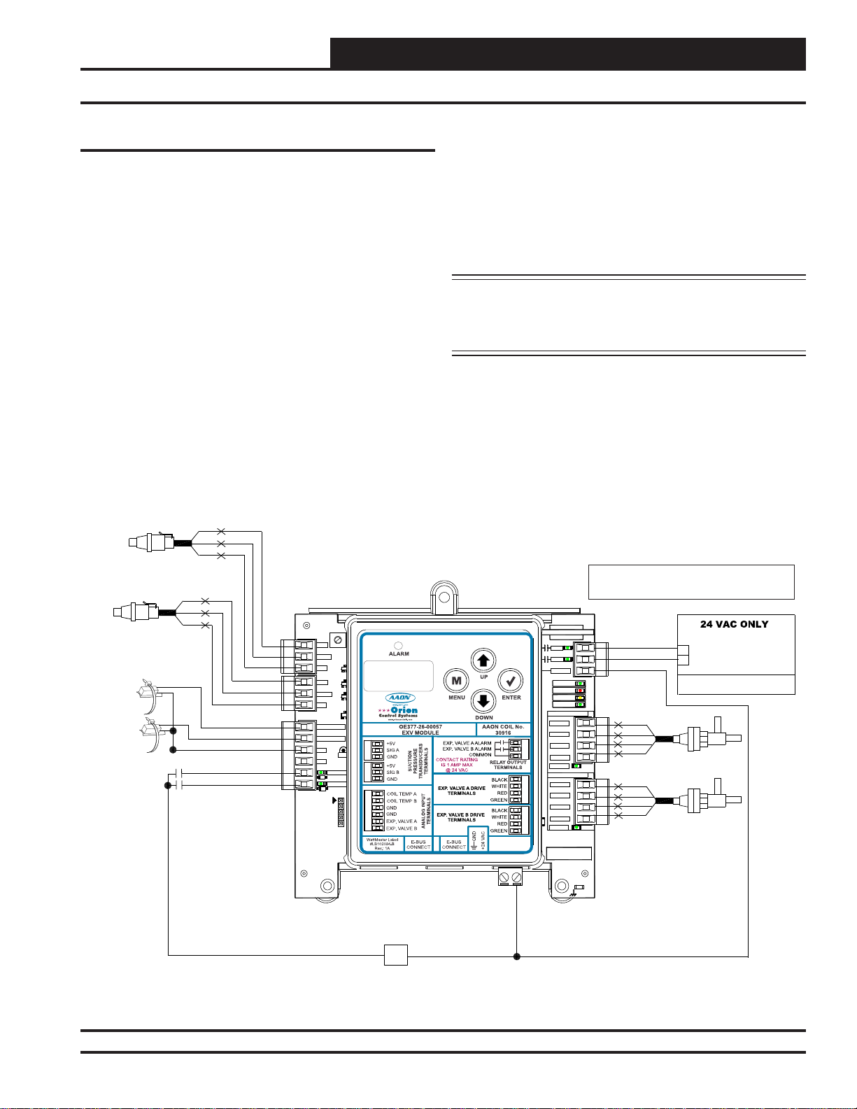
Installation & Wiring
Important Wiring Considerations
Please read carefully and apply the following information when wiring
the
Dual Electronic Expansion Valve Module Controller:
1. The Dual Electronic Expansion Valve Module requires a 24
VAC power connection with an appropriate VA rating.
2. Each Pressure Transducer must have its own 18-gauge
shielded twisted pair cable. The Drain Wire must be the “Gnd”
signal for the transducer.
3. All 24 VAC wiring must be connected so that all ground wires
remain common. Failure to follow this procedure can result in
damage to the module and connected devices.
COIL A - SUCTION
PRESSURE TRANSDUCER
COIL B - SUCTION
PRESSURE TRANSDUCER
COIL TEMP A
SENSOR
COIL TEMP B
SENSOR
RD
WH
BK
RD
WH
BK
Expansion Valve A
Expansion Valve B
GND
OE377-26-00057
Dual Electronic Expansion Valve
Module
R41
R41
TB2
TB2
+5V
+5V
SIGA
SIGA
D5
D5
GND
GND
D6
D6
+5V
+5V
D7
D7
SIG B
SIG B
GND
GND
D8
D8
TB3
TB3
COILTEMPA
COILTEMPA
COILTEMPB
COILTEMPB
GND
GND
GND
GND
GND
GND
VALVEA
VALVEA
D1
D1
VALVEB
VALVEB
D3
D3
TB4
TB4
J1
J1
4. All wiring is to be in accordance with local and
national electrical codes and specifi cations.
5. Check all wiring leads at the terminal block for tightness.
Be sure that wire strands do not stick out and touch adjacent
terminals. Confi rm that all transducers required for your
system are mounted in the appropriate location and wired into
the correct terminals.
WARNING: Observe polarity! All boards must be wired
GND-to-GND and 24 VAC-to-VAC. Failure to
observe polarity could result in damage to the
boards.
NOTE: NORMALLY
ALL RELAY OUTPUTS ARE
OPEN AND RATED FOR 24 VAC POWER ONLY
- 1 AMP MAXIMUM LOAD
YS102468 REV 3
YS102468 REV 3
WATTMASTER CONTROLS
WATTMASTER CONTROLS
MADE IN USA
MADE IN USA
TB1
RLYA
RLYA
RLYB
RLYB
COMMON
COMMON
VALVEA DRIVE
VALVEA DRIVE
BLACK
BLACK
WHITE
WHITE
RED
RED
GREEN
GREEN
DRIVING
DRIVING
VALVE B DRIVE
VALVE B DRIVE
BLACK
BLACK
WHITE
WHITE
RED
RED
C214
C214
.1uF
.1uF
GREEN
GREEN
DRIVING
DRIVING
SERIAL #
SERIAL #
STATUS
STATUS
ALARM
ALARM
COMM
COMM
POWER
POWER
TB1
RLYA
RLYB
COMM
VALVE A ALARM ENABLE
VALVE B ALARM ENABLE
HVAC UNIT CONNECTIONS
BK
WH
RD
GRN
TB7
TB7
TB6
TB6
EXPANSION VALVE A
BK
WH
RD
GRN
EXPANSION VALVE B
C31
C31
.1uF
.1uF
24 VAC
R
Figure 3: OE377-26-00057 Dual Electrical Expansion Valve Module Wiring Diagram
Technical Guide
7
Page 8
Dual Electronic Expansion Valve Module
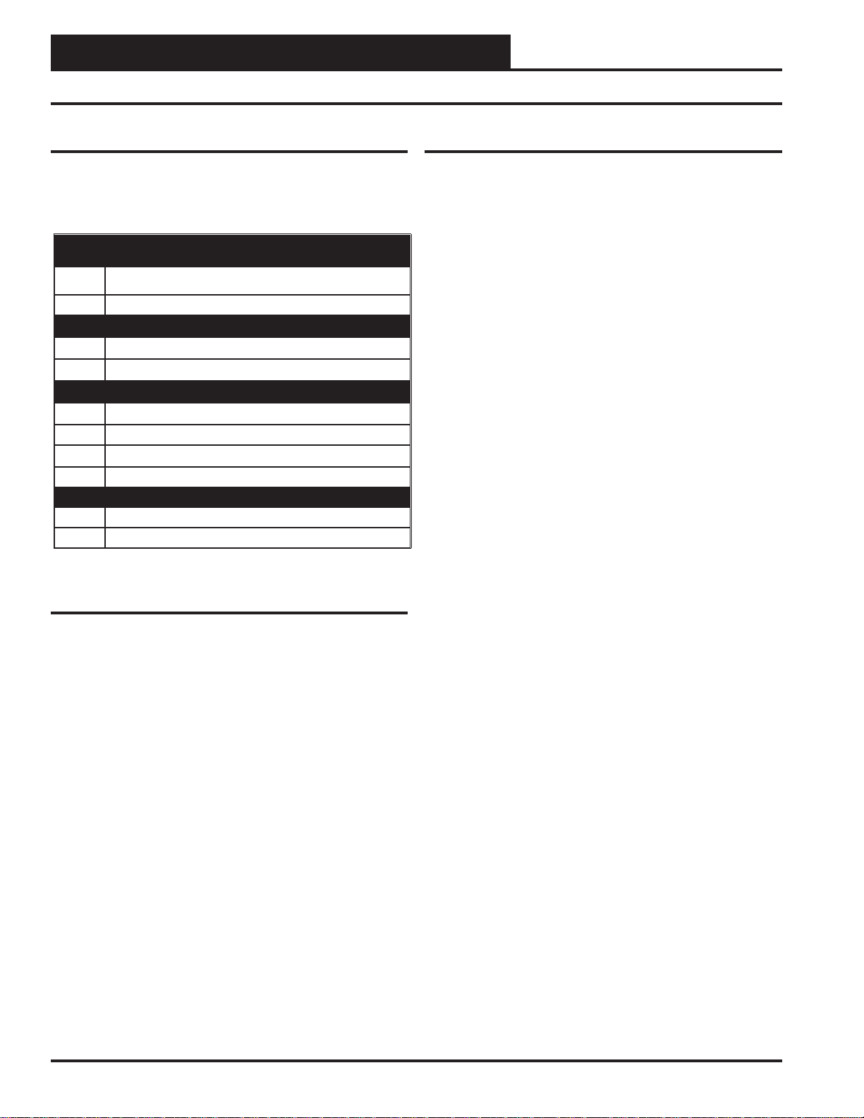
Inputs and Outputs
I/O Map
The following inputs and outputs are available on the Dual Electronic
Expansion Valve Module. See Table 2 below to reference the Input/
Output Map.
Binary Inputs
1 V alve A Enable
2 Valve B Enable
Binary Outputs
1 V alve A Alarm Relay
2 Valve B Alarm Relay
Analog Inputs
1 Coil A T emperature
2 Coil A Suction Pressure
3 Coil B Temperature
4 Coil B Suction Pressure
Stepper Motor Outputs
1 Expansion Valve A
2 Expansion Valve B
Stand-Alone Input Commands
Valve A Enable On/Off
A 24 volt signal to Binary Input #1 initiates the Valve A Enable
function. Once Valve A is enabled, it tries to maintain the desired
Superheat Setpoint. Valve A maintains the Superheat Setpoint until it loses the enable signal which then puts Valve A in Off mode.
Valve B Enable On/Off
A 24 volt signal to Binary Input #2 initiates the Valve B Enable
function. Once Valve B is enabled, it tries to maintain the desired
Superheat Setpoint. Valve B maintains the Superheat Setpoint until it loses the enable signal which then puts Valve B in Off mode.
Table 2: Dual Electronic Expansion Valve Module
Inputs & Outputs
8
Technical Guide
Page 9

Dual Electronic Expansion Valve Module
Sequence of Operation
Initialization
At power up, the Dual Electronic Expansion Valve Module will send
both expansion valves 110% of total steps in the closed position. This is
done to make sure that the valves always start from a valid 0% position.
For example, if the module is confi gured for a 6386 expansion valve,
the controller will step 7025 steps.
Normal Operation
The Dual Electronic Expansion Valve Module will continuously calculate the superheat for the different cooling circuits. The superheat will
be calculated by subtracting the saturated suction pressure from the
measured coil temperature at the suction line. The module is designed
for R410-A refrigerant.
The expansion valve signals will be maintained at the Smart Start position until the enable signal is activated. Anytime power is cycled, the
Smart Start will be 50%. After that, the Smart Start is based on the
history of the valve position.
The module will then modulate the expansion valve signals to maintain
the desired superheat.
The Superheat Setpoint and Time Constant are user-adjustable.
Force Mode
The electronic expansion valve is designed with the ability to manually
adjust the valve position by turning the Force Mode on for each valve.
The valve will reinitialize to zero when the Force Mode is turned back
off or after 1 hour. Each valve works independently.
• Force Mode Valve A – Ability to enable Valve A
Force Mode. Force Mode for Valve A will timeout
after 1 hour if not manually turned off.
• Force Valve A % - If Force Valve A mode is enabled,
you can manually adjust the valve position.
• Force Mode Valve B – Ability to enable Valve B
Force Mode. Force Mode for Valve B will timeout
after 1 hour if not manually turned off.
• Force Valve B % - If Force Valve B mode is
enabled, you can manually adjust the valve position.
Modulation Routine
The electronic expansion valve is designed with a modulation routine
that is used to try to maintain superheat as quickly and effi ciently as
possible. Currently, there are user adjustable setpoints that can be set
to adjust the modulation sequence to function better on a particular unit.
1. Modulation Rate (in seconds) – This setpoint will adjust how
often the modulation routine will make a valve adjustment. Some
systems are slower reacting than others, so setting this setpoint to
a higher value will slow down the response.
2. Proportional Window (in degrees) – This setpoint will adjust
how much of an adjustment will be made according to how far
away it is from setpoint. A smaller value will make larger changes
while a larger value will make smaller changes.
Technical Guide
9
Page 10

Dual Electronic Expansion Valve Module
Diagnostics
Alarms
The controller may have the following alarms for each refrigerant circuit:
• Low Suction Pressure
This alarm will be activated when the suction pressure
drops below 70 PSIG for longer than 10 seconds.Valve
will modulate by 10% one time when alarm occurs to
try to get suction pressure back up. This alarm will
cease when Suction Pressure is above 70 PSIG.
• High Superheat
This alarm will be activated when the Superheat
reaches 25 degrees for longer than 60 seconds. This
alarm will not affect valve operation. This alarm will
cease when the Superheat drops below 25 degrees.
• Low Superheat
This alarm will be activated when the Superheat
is 0 degrees for longer than 60 seconds. This alarm
will not affect valve operation. This alarm will cease
when the Superheat rises above 0 degrees.
Alarm LED’s will blink and the specifi c alarm can be accessed on the
LCD display. Also, the Relay will activate for the specifi c valve that
has the alarm.
LED Descriptions
The Dual Electronic Expansion Valve Module is equipped with LEDs
that can be used to verify operation and perform troubleshooting. There
are LEDs for communication, operation modes, and diagnostic codes.
The module has 11 LEDs—1 used for E-BUS communications, 8 used
for operation & status, and 2 used for alarms.
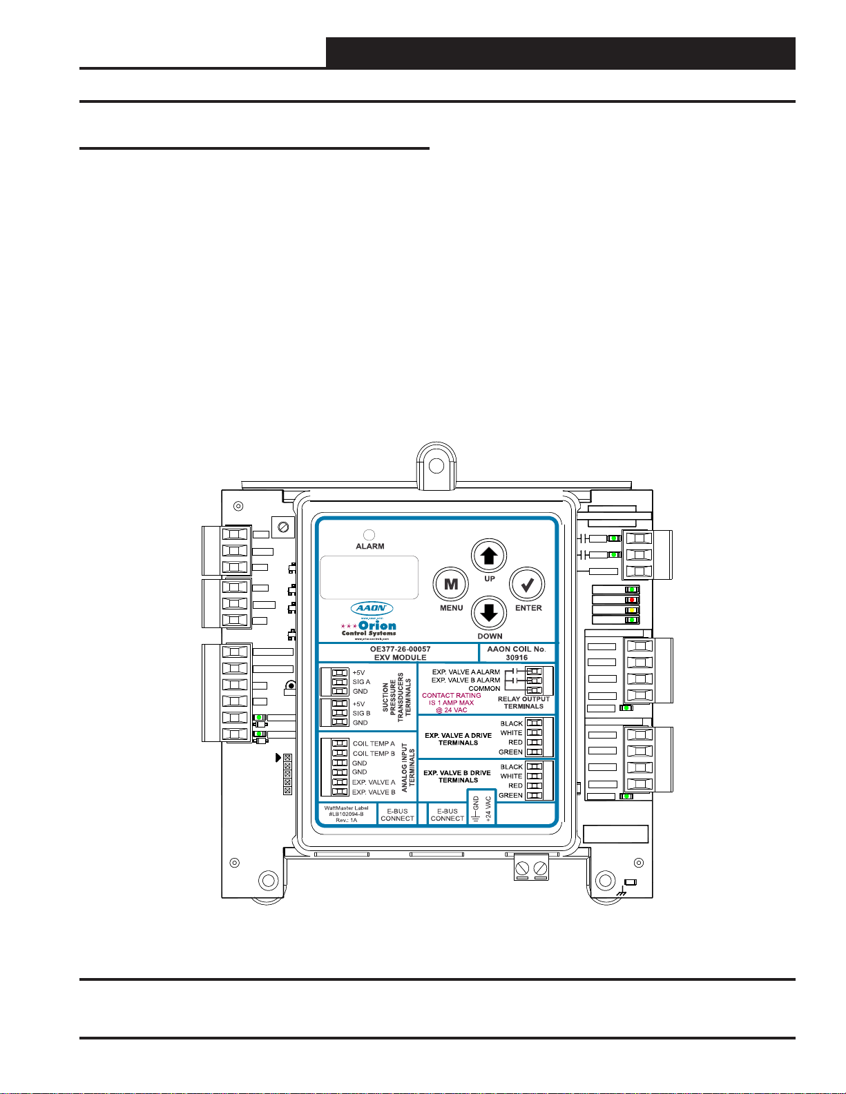
See Figure 4 for the LED locations. The LEDs associated with these
inputs and outputs allow you to see what is active without using a voltmeter. The LEDs and their uses are as follows:
Operation LEDs
POWER - This green LED will light up to indicate that 24 VAC power
has been applied to the module.
STATUS - This green LED will light up and blink the board address
at startup.
Diagnostic LEDs
ALARM - This red LED will light up to indicate an alarm. The type of
alarm will display on the LCD display. The ALARM LED also blinks
when the expansion valve is initializing at startup.
10
Technical Guide
Page 11

Dual Electronic Expansion Valve Module
Diagnostics
Communication LEDs
COMM - This yellow LED will light up and blink when E-BUS communications are detected.
Expansion Valve LEDs
DRIVING VALVE A - This green LED will light up when Expansion
Valve A is being driven open or closed.
DRIVING VALVE B - This green LED will light up when Expansion
Valve B is being driven open or closed.
ALARM LED
R41
R41
+5V
+5V
SIG A
SIG A
GND
GND
+5V
+5V
SIG B
SIG B
GND
GND
COILTEMPA
COILTEMPA
COILTEMP B
COILTEMP B
GND
GND
GND
GND
VALVEA
VALVEA
D1
D1
VALVEB
VALVEB
D3
D3
D6
D6
D7
D7
D8
D8
GND
GND
J1
J1
D5
D5
VALVE A & B
LEDs
TB2
TB2
TB3
TB3
TB4
TB4
Relay LEDs
RLYA - This green LED will light up when Valve A has an alarm and
will stay lit as long as Valve A relay is active.
RLYB - This green LED will light up when Valve B has an alarm and
will stay lit as long as Valve B relay is active.
Binary Input LEDs
V ALVE A - This green LED will light up when Valve A is enabled.
VALVE B - This green LED will light up when Valve B is enabled.
YS102468 REV 3
YS102468 REV 3
WATTMASTER CONTROLS
WATTMASTER CONTROLS
MADE IN USA
MADE IN USA
TB1
TB1
RLYA
RLYA
RLYB
RLYB
COMMON
COMMON
STATUS
STATUS
ALARM
ALARM
COMM
COMM
POWER
POWER
VALVEA DRIVE
VALVEA DRIVE
BLACK
BLACK
WHITE
WHITE
RED
RED
GREEN
GREEN
DRIVING
DRIVING
VALVE B DRIVE
VALVE B DRIVE
BLACK
BLACK
WHITE
WHITE
RED
RED
C214
C214
.1uF
.1uF
GREEN
GREEN
DRIVING
DRIVING
TB7
TB7
TB6
TB6
RELAY
LEDs
STATUS LED
ALARM LED
COMM LED
POWER LED
VALVE A
DRIVING LED
VALVE B
DRIVING LED
Figure 4: Dual Electrical Expansion Valve Module LED Locations and Descriptions
Technical Guide
SERIAL #
SERIAL #
C31
C31
.1uF
.1uF
11
Page 12

Dual Electronic Expansion Valve Module
Navigation Keys and Main Screens Map
LCD Display Screen & Navigation
Keys
The Dual Electronic Expansion Valve Module allows you to make confi guration changes, view status, change setpoints, create force modes,
and perform diagnostics using the keypad next to the LCD display. See
Figure 5 and refer to Table 3 for descriptions.
Figure 5: LCD Display and Navigation Keys
Navigation Key Key Function
MENU
Use the MENU key to navigate through the
Main Menu Screens
Main Screens Map
Refer to the following map when navigating through the LCD Main
Screens. The fi rst two screens are initialization screens. To scroll through
the rest of the screens, press the <MENU> button.
ADDRESS
#
DUAL EXV
STARTUP!
DUAL EXV
CONTROL
Press to scroll through DUAL EXV Screens.
Press to go to STATUS V-A Screens.
STATUS
V-A
Press to scroll through STATUS V-A Screens.
Press to go to STATUS V-B Screens.
STATUS
V-B
UP
DOWN
ENTER
Use this key to adjust setpoints and change
confi gurations. This key is also used to turn
Valve Force Mode on.
Use this key to adjust setpoints and change
confi gurations. This key is also used to turn
Valve Force Mode off.
Use the Enter key to move through screens
within Main Menu categories. Also, use this
key to save setpoints and confi guration
changes.
Table 3: Navigation Key Functions
Press to scroll through STATUS V-B Screens.
Press to go to V-A ALARM Screens.
NO V-A
ALARMS
Press to scroll through V-A ALARM Screens.
Press to go to V-B ALARM Screens.
NO V-B
ALARMS
Press to scroll through V-B ALARM Screens.
Press to go to FORCE VALVE Screens.
FORCE
VALVES
Press to scroll through FORCE VALVE Screens.
12
Technical Guide
Page 13

Dual Electronic Expansion Valve Module
Protected Screens Map and Main Menu Screens
Protected Screens Map
Refer to the following map when navigating through the LCD Protected
Screens. From the DUAL EXV CONTROL Screen, press <ENTER>
twice to get to the Software Screen. Then hold the <UP> button for 5
seconds. T o scroll through the rest of the screens, press the <MENU>
button.
DUAL EXV
CONTROL
S/A MODE
SOFTWARE
TESTv108
Hold for 5 seconds.
Main (Dual EXV Control) Screens
Refer to the following map when navigating through the Main Screens.
From the DUAL EXV CONTROL Screen, press <ENTER> to scroll
through the screens.
DUAL EXV
CONTROL
S/A MODE
STAND ALONE MODE
SOFTWARE
TESTv108
CURRENT SOFTWARE VERSION
You can access the protected
screens from this screen by holding
the <UP> button for 5 seconds.
SETPOINT
CONFIG
DIAGNSTC
ENTER TO
EXIT
ADDRESS
#
CURRENT BOARD ADDRESS
VLVSTEPS
2500
CURRENT VALVE CONFIGURATION
(STEP SIZE)
Technical Guide
13
Page 14

Dual Electronic Expansion Valve Module
Status V-A/B and V-A/B Alarm Screens
Status V-A & V-B Screens
Refer to the following map when navigating through the Status Valve
A Screens. From the STATUS V-A or STATUS V-B Screen, press
<ENTER> to scroll through the screens.
STATUS
V-A/B
V-A/B MODE
ON/OFF/FORCE
VALVE A/B MODES: ON ,OFF, FORCE
ON: Valve is modulating to maintain Superheat.
OFF: System is off.
FORCE: Valve is set to a forced position.
COIL TMP
XX.X
COIL TEMPERATURE READING FROM
TEMPERATURE SENSOR INPUT
CALC TMP
XX.X
CALCULATED COIL TEMPERATURE
FROM SUCTION PRESSURE INPUT
SUC PRESS
XXX
SUCTION PRESSURE READING
FROM INPUT
V-A/B POS
0 TO 100%
VALVE POSITION
0 to 100 percent
SUPRHEAT
XX.X
CURRENT SUPERHEAT CALCULATION
SUPRHEAT SP
O TO 25
SUPERHEAT SETPOINT SETTING
0 to 25
V-A & V-B Alarm Screens
Refer to the following map when viewing Valve A and Valve B Alarm
Screens. These screens will display automatically when alarms are
present.
V-A/B
ALARMS
ALARMS
The alarms are as follows:
NO V-A/B ALARMS: This will be shown if there are no current alarms.
LO SPRESS: This indicates a Low Suction Pressure Alarm condition
which is activated when the Suction Pressure drops below 70 PSIG for
longer than 10 seconds. The valve will modulate by 10% one time when
alarm occurs to try to increase the suction pressure. This alarm will disable when Suction Pressure is above 70 PSIG.
HI SHEAT: This alarm will be activated when the Superheat reaches
25 degrees for longer than 60 seconds. This alarm will not affect valve
operation. This alarm will disable when the Superheat drops below 25
degrees.
LO SHEAT: This alarm will be activated when the Superheat is 0
degrees for longer than 60 seconds. This alarm will not affect valve
operation. This alarm will disable when the Superheat rises above 0 degrees
14
Technical Guide
Page 15

Dual Electronic Expansion Valve Module
Force Valves Screens
Force Valves Screens
Refer to the following map when navigating through the Force Valves
Screens. From the FORCE VALVE Screen, press <ENTER>. At the
FORCE MODE ON/OFF screens, press the <UP> arrow key to turn
the valve on and press the <DOWN> arrow key to turn the valve off.
Use the <UP> and <DOWN> arrow keys to increase and decrease
the percentage.
FORCE
VALVES
FRC V-A
MODE ON/OFF
Press the <UP> button to turn the valve on.
Press the <DOWN> button to turn the valve off
Force Valve will timeout after 1 hour
if not manually turned off.
FRC V-B
MODE ON/OFF
Press the <UP> button to turn the valve
on. Press the <DOWN> button to turn
the valve off.
Force Valve will timeout after 1 hour
if not manually turned off.
FRC V-B
%
FORCE VALVE PERCENTAGE
If Force Valve B is enabled, you can manually
adjust the valve position.
Press the <UP> button to increase the
percentage. Press the <DOWN> button to
decrease the percentage.
FRC V-A
%
FORCE VALVE PERCENTAGE
If Force Valve A is enabled, you can manually
adjust the valve position.
Press the <UP> button to increase the
percentage. Press the <DOWN> button to
decrease the percentage.
NOTE: When you turn the Force Valve back
off or after 1 hour has elapsed, the valve will
reinitialize to zero.
NOTE: When you turn the Force Valve back
off or after 1 hour has elapsed, the valve will
reinitialize to zero.
FORCE
TIMEOUT
FORCE MODE TIME OUT
This screen will appear when the
Force Mode times out after 1 hour.
Technical Guide
15
Page 16

Dual Electronic Expansion Valve Module
Setpoints Screens
Setpoints Screens
Refer to the following map when navigating through the Setpoints
Screens. From the SETPOINTS Screen, press <ENTER> to
scroll through the screens and change setpoints. Use the <UP>
and <DOWN> arrow keys to change your selections. Then press
<ENTER> to save the new setpoint.
SETPOINTS
SHEAT SP
0 TO 25
SUPERHEAT SETPOINT
One setpoint is used for both valves
Default = 9
MODRATE
O TO 180
MODULATION RATE (in seconds)
This setpoint will adjust how often the modulation routine
will make a valve adjustment. Some systems are
slower reacting than others, so setting this setpoint to a
higher value will slow down the response.
PROPORTIONAL WINDOW (in degrees)
This setpoint will adjust how much of an adjustment will be
made according to how far away it is from setpoint. A
smaller value will make larger changes while a larger
value will make smaller changes.
Default = 30
PROP WIN
0 TO 30
Default = 30
16
Technical Guide
Page 17

Dual Electronic Expansion Valve Module
Confi guration Screens
Confi guration Screens
Refer to the following map when navigating through the Confi guration
Screens. From the CONFIG Screen, press <ENTER> to scroll through
the screens and change setpoints. Use the <UP> and <DOWN> arrow
keys to change your selections. Press <ENTER> to save any changes.
CONFIG
ADDRESS
1 TO 4
CURRENT ADDRESS OF THE BOARD
The address confi guration is not used in Stand
Alone Mode. Stand Alone Mode Default is 1.
MAX VLV%
0 TO 100
MAXIMUM VALVE POSITION
The maximum position each valve will modulate (%).
Default =100
MIN VLV%
0 TO 100
MINIMUM VALVE POSITION
The maximum position each valve will modulate (%).
Default = 0
SP-A CAL
-10 TO 10
VALVE B
ENABLED/
DISABLED
VALVE B ENABLED/DISABLED
When using the module for only one valve, valve
B can be disabled so false information is not dis-
played such as alarms and sensor readings.
VLVSTEPS
1596,2500,
3193,6386
VALVE STEPS
Confi gurable for what valve is being used
(1596, 2500, 3193, 6386)
Default = 2500
SUCTION PRESSURE VALVE A
CALIBRATION OFFSET
If the Suction Pressure Sensor is reading incorrectly,
you can use this offset to adjust its reading.
Default = 0
SP-B CAL
-10 TO 10
SUCTION PRESSURE VALVE B
CALIBRATION OFFSET
If the Suction Pressure Sensor is reading incorrectly,
you can use this offset to adjust its reading.
Default = 0
Technical Guide
17
Page 18

Dual Electronic Expansion Valve Module
Diagnostic Screens
Diagnostic Screens
Refer to the following map when navigating through the Diagnostic
Screens. From the DIAGNSTC Screen, press <ENTER> to scroll
through the screens.
DIAGNSTC
WDOG CNT
#
WATCH DOG TIMER
Displays the number of times the board has been reset due
to watchdog timer overfl ow .
PWER CNT
#
POWER LOSS COUNT
Displays the number of times the board has been reset due
to power loss.
18
Technical Guide
Page 19

Dual Electronic Expansion Valve Module
Dual Electronic Expansion Valve
Module Troubleshooting
Valve Enable Outputs Not Working
Make sure 24 VAC is applied and the LEDs are lit.
Electronic Expansion Valve Outputs
Not Working
• Make sure the valves are wired correctly according to
the colored wires shown on the module.
• Make sure the correct valve size is confi gured.
• Monitor the LEDs to see if the valve is modulating.
• Valve may not modulate if Superheat is at the Superheat
Setpoint.
Troubleshooting
Technical Guide
19
Page 20

Dual Electronic Expansion Valve Module
Troubleshooting
OE275-01 Suction Pressure Transducer
T esting for R410A Refrigerant
The Evaporator Coil Temperature is calculated by converting the Suction Pressure to T emperature. The Suction Pressure is obtained by using
the OE275-01 Suction Pressure Transducer , which is connected into the
Suction Line of the Compressor.
The Suction Pressure and Calculated Temperature is displayed in the
Module’s Status Screens. A voltage measurement can also be taken on
input for verifi cation.
The Suction Pressure Transducer must have a 5 volt supply voltage to
work properly. A measurement can be taken on the +5V terminal for
verifi cation.
Use the voltage column to check the Suction Pressure Transducer while
connected to the Dual Electronic Expansion V alve Module. Read voltage
with a meter set on DC volts. If the temperature/voltage or pressure/voltage readings do not align closely with the chart, your Suction Pressure
Transducer is probably defective and will need to be replaced.
See the OE275-01 Suction Pressure Transducer , Pressure, T emperature,
and Voltage Chart for R410A Refrigerant testing (Table 4). The chart
shows a temperature range from 20°F to 80°F . For troubleshooting purposes, the DC Voltage readings are also listed with their corresponding
temperatures and pressures.
OE275-01 Suction Pressure Transducer Coil Pressure
– Temperature – Voltage Chart for R410A Refrigerant
°F
Temperature
21.19 80.94 1.8 59.03 168.10 3.2
24.49 87.16 1.9 61.17 174.32 3.3
27.80 93.39 2.0 63.19 180.55 3.4
30.99 99.62 2.1 65.21 186.78 3.5
33.89 105.84 2.2 67.23 193.00 3.6
36.80 112.07 2.3 69.24 199.23 3.7
39.71 118.29 2.4 71.15 205.46 3.8
42.30 124.52 2.5 72.95 211.68 3.9
44.85 130.75 2.6 74.76 217.91 4.0
47.39 136.97 2.7 76.57 224.14 4.1
49.94 143.2 2.8 78.37 230.36 4.2
52.23 149.42 2.9 80.18 236.59 4.3
54.50 155.65 3.0
56.76 161.88 3.1
PSI
Pressure
Signal
DC Volts
°F
Temperature
PSI
Pressure
Signal
DC Volts
Table 4: Coil Pressure/Voltage/Temp for OE275-01
Suction Pressure Transducers - R410A Refrigerant
20
Technical Guide
Page 21

Dual Electronic Expansion Valve Module
Troubleshooting
Coil Temperature Sensor Testing
The following sensor voltage and resistance table is provided to aid in
checking a coil temperature sensor that appears to be operating incorrectly. Many system operating problems can be traced to incorrect sensor
wiring. Be sure the sensor is wired per the wiring diagrams in this manual.
The Suction Pressure and Calculated Temperature is displayed in the
Module’s Status Screens. A voltage measurement can also be taken on
input for verifi cation.
If the sensors still do not appear to be operating or reading correctly,
check voltage and/or resistance to confi rm that the sensor is operating
correctly per the tables. Please follow the notes and instructions that
appear after the chart when checking sensors.
Temperature – Resistance – Voltage for Type III
10 K Ohm Thermistor Sensors
Temp
(ºF)
-10 -23.33 93333 4.51
-5 -20.55 80531 4.45
0 -17.77 69822 4.37
5 -15 60552 4.29
10 -12.22 52500 4.2
15 -9.44 45902 4.1
20 -6.66 40147 4.002
25 -3.88 35165 3.891
30 -1.11 30805 3.773
35 1.66 27140 3.651
40 4.44 23874 3.522
45 7.22 21094 3.39
50 10 18655 3.252
52 11.11 17799 3.199
54 12.22 16956 3.143
56 13.33 16164 3.087
58 14.44 15385 3.029
60 15.55 14681 2.972
62 16.66 14014 2.916
64 17.77 13382 2.861
66 18.88 12758 2.802
68 20 12191 2.746
69 20.55 11906 2.717
70 21.11 11652 2.691
71 21.66 11379 2.661
Table 5: Temperature/Resistance for Type III 10K
Ohm Thermistor Sensors
Temp
(ºC)
Resistance
(Ohms)
Voltage @
Input (VDC)
Temperature – Resistance – Voltage for Type III
10 K Ohm Thermistor Sensors
Temp
(ºF)
72 22.22 11136 2.635
73 22.77 10878 2.605
74 23.33 10625 2.576
75 23.88 10398 2.549
76 24.44 10158 2.52
77 25 10000 2.5
78 25.55 9711 2.464
80 26.66 9302 2.41
82 27.77 8893 2.354
84 28.88 8514 2.3
86 30 8153 2.246
88 31.11 7805 2.192
90 32.22 7472 2.139
95 35 6716 2.009
100 37.77 6047 1.884
105 40.55 5453 1.765
110 43.33 4923 1.65
115 46.11 4449 1.54
120 48.88 4030 1.436
125 51.66 3656 1.339
130 54.44 3317 1.246
135 57.22 3015 1.159
140 60 2743 1.077
145 62.77 2502 1.001
150 65.55 2288 0.931
Temp
(ºC)
Resistance
(Ohms)
Voltage @
Input (VDC)
Table 5, cont.: Temperature/Resistance for Type III
10K Ohm Thermistor Sensors
Thermistor Sensor Testing Instructions
Use the resistance column to check the thermistor sensor while disconnected from the controllers (not powered).
Use the voltage column to check sensors while connected to powered
controllers. Read voltage with meter set on DC volts. Place the “-”
(minus) lead on GND terminal and the “+” (plus) lead on the sensor
input terminal being investigated.
If the voltage is above 4.88 VDC, then the sensor or wiring is “open.” If
the voltage is less than 0.05 VDC, then the sensor or wiring is shorted.
Technical Guide
21
Page 22

Dual Electronic Expansion Valve Module
Notes
22
Technical Guide
Page 23

Dual Electronic Expansion Valve Module
Notes
Technical Guide
23
Page 24

www.aaon.com
AAON Coil Products
203 Gum Springs Road • Longview, TX 75602-1721
Ph: (903) 236-4403 • Fax: (903) 236-4463
WattMaster Manual Form No: AA-EXV-TGD-01A
 Loading...