

Page 1
www.orioncontrols.com
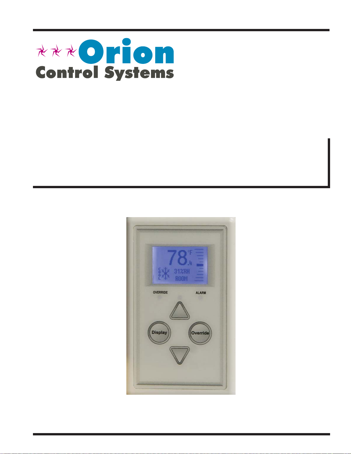
Digital Room Sensor
Technical Guide
Page 2
TABLE OF CONTENTS
OVERVIEW ....................................................................................................................................... 3
BASIC OPERATION .......................................................................................................................... 4
Sensor Operation .....................................................................................................................................................4
LED Operation .........................................................................................................................................................4
MOUNTING AND WIRING ................................................................................................................ 5
Environmental Requirements ...................................................................................................................................5
Indoor Reading Range ........................................................................................................................................5
Outdoor Reading Range .....................................................................................................................................5
Important Wiring Considerations ..............................................................................................................................5
Mounting ..................................................................................................................................................................5
SENSOR OPERATION ...................................................................................................................... 6
Main Sensor Display Screens....................................................................................................6
Temperature and Humidity Status Screen ..........................................................................................................6
Outside Air Temperature Humidity Status Screen...............................................................................................6
Unit Information Screen ......................................................................................................................................6
Setpoint Adjust Screen ........................................................................................................ ...............................6
TROUBLESHOOTING ....................................................................................................................... 7
Temperature Sensor Testing for OE217-00 .............................................................................................................7
APPENDIX ....................................................................................................................................... 8
Sensor Confi guration and Test Screens ..................................................................................................................8
Sensor Confi guration & Test Screen ...................................................................................................................8
Pixel Test Screen ................................................................................................................................................8
Sensor Info & LED Test Screen ..........................................................................................................................8
LCD Backlight Test Screens ...............................................................................................................................9
Thermistor Averaging Screen .............................................................................................................................9
Display Options - Temperature/Setpoint .............................................................................................................9
Connecting to VAV/Zone Controller & HVAC Unit Controller .................................................................................10
Connecting a Remote Sensor ................................................................................................................................ 11
Mounting Plate Dimensions ...................................................................................................................................12
PART NUMBER CROSS REFERENCE TABLE
PART DESCRIPTION ORION
Digital Room Sensor Temp Only OE217-00
Digital Room Sensor Temp & Humidity OE217-01
Mounting Plate BK000081
Space CO
Duct Mounted CO
Return Air Temperature Sensor OE231
VCM-X E-BUS Controller OE332-23E-VCMX
Sensor OE256-01
2
Sensor OE256-02
2
www.orioncontrols.com
WattMaster Controls Inc.
8500 NW River Park Drive · Parkville, MO 64152
Toll Free Phone: 866-918-1100
PH: (816) 505-1100 · FAX: (816) 505-1101 ·
E-mail: mail@wattmaster.com
Visit our web site at www.orioncontrols.com
®
is a registered trademark of AAON, Inc., Tulsa, OK.
AAON
WattMaster Controls, Inc. assumes no responsibility for errors
or omissions.
This document is subject to change without notice.
Form: OR-DRS-TGD-01K
Copyright May 2015 WattMaster Controls, Inc.
Page 3
DIGITAL ROOM SENSOR
Overview
Overview
The OE217 series of Digital Room Sensors are used to sense Space T emperature only or Space Temperature & Space Humidity. See Figure 1.
The OE217-00 model is the Space T emperature Sensor only model and
can be used with the VCM-X E-BUS Controller (OE332-23E-VCMX),
RNE Controller (OE332-23E-RNE), SA E-BUS Controller (OE332-23EVCMX-SA), and VAV/Zone Controller (OE324-02). The OE217-01 is
a combination Space Temperature & Space Humidity Sensor model
and can only be used with the VCM-X E-BUS, RNE, and SA-EBUS
Controllers.
The sensor provides the following useful functions:
• Provides 112 x 64 monochrome Graphical LCD display with
LED backlight
• Displays the Current Space Temperature or Cooling/Heating
Setpoint on the Main Display Screen
• Displays Outdoor Air Temperature (if controller is confi gured
with OA Temperature Sensor)
• Displays the Current Space Humidity (OE217-01 Model
Only)
• Displays Outdoor Air Relative Humidity (OE217-01 Model if
controller is confi gured with OA Humidity Sensor)
• Displays the Current Zone Setpoint Temperature
• Equipped with Push Buttons for changing the Zone Setpoint
Temperature
• Equipped with an Override Button for forcing the VAV/Zone
Controller or VCM-X / RNE / SA Controller into Occupied
Operation from Unoccupied Operation
• Provides graphics to indicate the Mode of Operation
• Provides LEDs to indicate Schedule Override, Button Push,
and Alarms
• Can display Temperature reading from a Remote Sensor (see
Figure 19, page 11 for instructions)
• Can be used with the OE256-01 or OE256-02 CO2 Sensor (see
notes in Figures 17 & 18, page 10 for instructions)
Both sensors connect to the controllers using various lengths of
TSDRSC modular cables connected between the controller and the
sensor. The TSDRSC modular cables should not run in conduit with
other AC line voltage wiring or with any conductors carrying highly
inductive loads.
Figure 1: Digital Room Sensor
Operator Interface 3
Page 4
DIGITAL ROOM SENSOR
Basic Operation
Sensor Operation
When power is fi rst applied to the OE217-00 Digital Room Sensor, the
sensor will display the Current Room T emperature or the Cooling/Heating Setpoint and the current setting of the slide offset. The OE217-01
model will also display Relative Humidity.
NOTE: The sensor readings are not accurate until the controller
that the sensor is connected to is done calibrating.
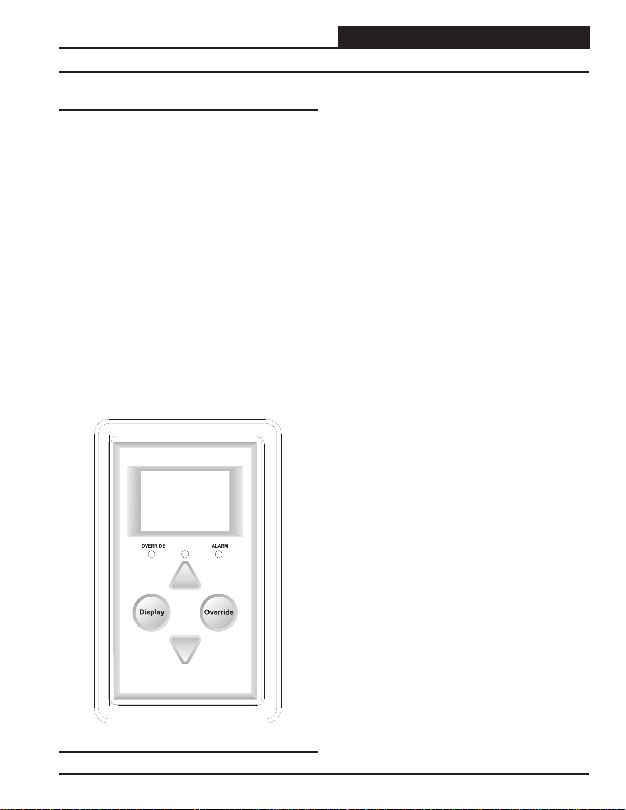
The sensor has 4 buttons—
<Down>. You can also access certain functions by touching the area
below the <Display> and <Override> buttons. The sensor has 3
LEDs—one to indicate an Override, one to indicate an Alarm, and one
to indicate that a button has been pressed. See Figure 2 for LED and
Button Descriptions.
An icon for the current mode of operation will appear in the sensor
display. The operation mode icons are a Snowfl ake for Cooling Mode,
a Flame for Heating Mode, a Fan in motion for Vent Mode, and a Moon
for Unoccupied Mode. When the unit is in Unoccupied Mode, the
screen’s background will turn dark. See Figur e 8, page 6 for examples
of operation modes.
<Display>, <Override>, <Up>, and
LED Operation
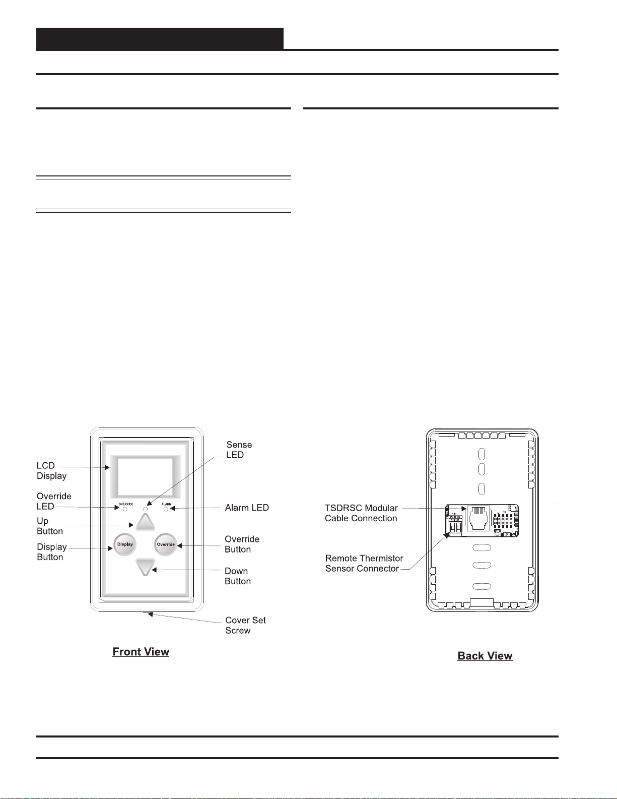
Refer to Figure 2 below for LED locations.
Alarm LED: The Alarm LED will blink when there is an alarm from
the Controller.
Sense LED: The Sense LED will blink when the sensor gets a valid
touch.
Override LED: The Override LED is inoperable when in Occupied
Mode. In Unoccupied Mode, if you touch the
Override LED will blink, indicating an override request. The Controller will respond by sending the unit into override. The Override LED
will then stay on for the duration of the Override. Any time the Unit
is in Override, you can request to cancel the override by touching the
<Override> button, and the Override LED will blink. The Unit will
then cancel the override. The Override LED will then turn off.
<Override> button, the
Figure 2: Digital Room Sensor Components
4
Operator Interface
Page 5
DIGITAL ROOM SENSOR
Mounting and Wiring
Environmental Requirements
The Digital Room Sensor needs to be installed in an environment that
does not exceed a temperature greater than 150°F or less than -30°F and
does not exceed 90% relative humidity levels (non-condensing).
Indoor Reading Range
The Digital Room Sensor’s Indoor Reading Range is 40°F to 120°F and
0-100% RH (RH is available on the OE217-01 Model). Its temperature
reading accuracy is +/- .5°F, and its RH reading accuracy is +/-2%. Its
sensor element is the integral communicating digital sensing device or
external Type III Thermistor 10K Ohm @ 77°F.
Outdoor Reading Range
If your Digital Room Sensor is set up to read an Outdoor Air T emperature
Sensor, any outdoor air temperature below -40°F will not appear on the
Digital Room Sensor’s display.
Important Wiring Considerations
The OE217-00 and OE217-01 Space Sensors connect to the VCM-X
Controller, RNE, SA-E-BUS, or VA V/Zone Controller (OE217-00 only)
using various lengths of TSDRSC modular cables connected between
the controller and the sensor. The TSDRSC modular cables should not
run in conduit with other AC line voltage wiring or with any conductors
carrying highly inductive loads. See Figures 17 & 18, page 10 for wiring.
Mounting
CAUTION: Do not touch the front face of the sensor while you
are plugging in the modular sensor cable. Touching the front face
of the sensor while plugging in the cable may prevent proper initialization and keep the buttons on the sensor from working properly.
The Digital Room Sensor is designed to be mounted to a vertical 2” x
4” electrical box recessed in the wall. If the wall cannot be penetrated,
a plastic surface mount box such as those made by Wiremold
used to mount the sensor to the wall surface.
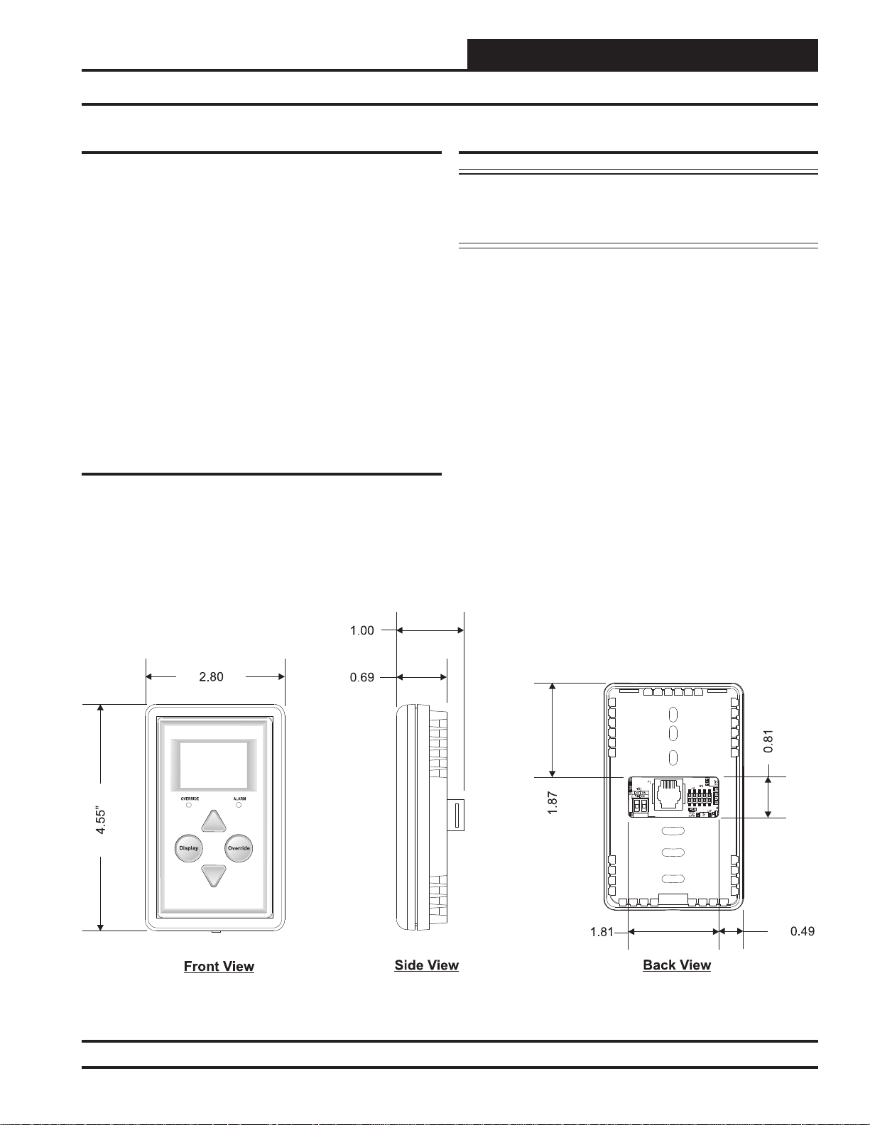
The Sensor is mounted by removing the front cover and fastening the
housing base to the electrical box using the supplied (2) 6/32” x 1” machine
screws. The modular cable is then plugged into the phone jack located
on the circuit board that is mounted on the cover. The cover is then
placed onto the housing base, and the Allen Screw on the bottom of the
base is adjusted to hold the cover in place. A locking screw secures the
sensor to the wall. See Figure 3 for Digital Room Sensor dimensions.
Optional Mounting Plate
Included with the Digital Room Sensor is a mounting plate that
can be used, if necessary, to cover the sensor sheet rock opening.
This mounting plate screws onto the back of the housing base.
The mounting plate is then mounted and covers the recessed space
in the wall. A locking screw secures the sensor to the wall. See
Figure 20, page 12 for dimensions.
TM
may be
Figure 3: Digital Room Sensor Dimensions
Operator Interface
5
Page 6

DIGITAL ROOM SENSOR
Sensor Operation
Main Sensor Display Screens
There are 3 Main Sensor Display Screens. The fi rst screen displays
the Current Room Temperature or Cooling/Heating Setpoint, Operation Mode, Slide Offset, and RH (RH is available on the OE217-01
Model). The second screen displays the Outside Air Temperature and/
or Humidity if Outdoor Air Temperature and/or Outdoor Air Humidity
is being monitored. The third screen displays the unit information for
the controller that the Digital Room Sensor is connected to.
Temperature and Humidity Status
Screen
The Main Display Screen dis-
plays the current room temperature or Cooling/Heating
Setpoint, the humidity in the
room (RH is available on the
OE217-01 Model), the current
setting of the slide offset, and
an icon for the current mode of
Figure 4: Main Display
Screen
The different icons shown are a Snowfl ake for cooling mode, a Flame for
heating mode, a Fan in motion for vent mode, and a Moon for unoccupied
mode. When the unit is in unoccupied mode, the screen’s background
will turn dark. Refer to Figure 8 for operation mode screen examples.
operation once the controller it is
connected to is done calibrating.
Setpoint Adjust Screen
Touching <> or <> will dis-
play the Setpoint Adjust Screen.
You can adjust the cooling and
heating setpoints from this screen
based on the VCM-X controller
or VAV/Zone controller slide offset setpoint. For example, if the
connected controller’s Max Slide
Figure 7: Setpoint Adjust
Screen
NOTE: If the VCM-X Controller or VAV/Zone Controller’s slide
offset setpoint is set to Zero, this screen will not appear
when you touch <> or <>.
Offset Setpoint is set for fi ve, you
can adjust the setpoint up fi ve
degrees and down fi ve degrees.
Cooling Mode
with Snowfl ake Icon
Outside Air Temperature Humidity
Status Screen
If the connected controller is
receiving an outdoor air temperature and/or humidity broadcast,
touching <Display> will fi rst
bring up the Outdoor Status
Screen.
Figure 5: Outdoor Status
Screen
Unit Information Screen
Touching <Display> again will
bring up the Unit Information
Screen which contains the controller’s address or ID number,
screen ID, and software version
of the controller connected to
the sensor.
Figure 6: Unit
Information Screen
Heating Mode
with Flame Icon
Vent Mode
with Fan in Motion Icon
Unoccupied Mode
with Moon Icon
Figure 8: Operation Mode Screens
6
Operator Interface
Page 7

DIGITAL ROOM SENSOR
Troubleshooting
Temperature – Resistance – Voltage for
Type III 10K Ohm Thermistor Sensors
Temp
(ºF)
-10 93333
-5 80531
0 69822
5 60552
10 52500
15 45902
20 40147
25 35165
30 30805
35 27140
40 23874
45 21094
50 18655
52 17799
54 16956
56 16164
58 15385
60 14681
62 14014
64 13382
66 12758
68 12191
69 11906
70 11652
Resistance
(Ohms)
Temperature – Resistance – Voltage for
Type III 10K Ohm Thermistor Sensors
Temp
(ºF)
71 11379
72 11136
73 10878
74 10625
75 10398
76 10158
78 9711
80 9302
82 8893
84 8514
86 8153
88 7805
90 7472
95 6716
100 6047
105 5453
110 4923
115 4449
120 4030
125 3656
130 3317
135 3015
140 2743
145 2502
150 2288
Table 1: Temperature/Resistance for Type III 10K Ohm Thermistor Sensors
Resistance
(Ohms)
T
9302
+
-
TSDRSC Cable
Disconnected
Sensor To The
VAV/Zone or VCM-X
Controller Modular
Sensor Port
Figure 9: Temperature/Resistance Testing
Operator Interface
-
From
+
Digital Room Sensor
Back View
NOTE: ,
For This Test The Sensor Must Be Disconnected From
Its TSDRSC Cable As Shown. The Meter Must Be Set To
Measure Resistance in Ohms. Use To Determine If The
Sensor Is Reading The Correct Resistance Value For The
Ambient Temperature. This Resistance Value Should Match The
Temperature Value Listed Next To The Resistance Value In The
Table. The Temperature Should Be Measured With A Separate
Accurate Temperature Measuring Device Located In The Area
Where The Sensor Is Currently Located.
Test Points Labeled
“Extern Therm” On
Sensor Circuit Board
256GP206
PIC24HJ
MICROCHIP
Table 1
7
Page 8

DIGITAL ROOM SENSOR
Appendix
Sensor Confi guration and Test
Screens
To access the Sensor Confi guration & Test Screens, you fi rst need to
access the Unit Information Screen by touching <Display> while at
the Main Display Screen.
NOTE: While in the Sensor Confi guration & Test Screens, the
<Display> button functions as an exit key to return to the
previous screen or menu. After a few seconds, however ,
the sensor will automatically revert to the Main Display
Screen. Refer to Figure 10 when reading the instructions
that follow.
Figure 10: Digital Room Sensor Buttons
Pixel Test Screen
To select the first option—
Pixels—touch <> while at
the Sensor Configuration &
Test Screen (Figure 11). The
Pixel T est Screen tests the pixels
of the LCD display, allowing
you to make the screen white
with black characters, black
Figure 12: Sensor Info &
LED Test Screen
with white characters, or a
black or white screen. To exit
this screen, touch
Sensor Info & LED Test Screen
To select the second option—
Info & LEDS—touch < >
while at the Sensor Confi gura-
tion & Test Screen (Figure 11).
The Sensor Info & LED Test
Screen shows the version of
software that the sensor is run-
Figure 13: Sensor Info &
LED Test Screen
ning and allows you to test the
LEDs that are used on the controller. Touching <> will turn
the LEDs on and touching <>
will turn the LEDs off. To exit
this screen, touch <Display>.
<Display>.
Sensor Confi guration & Test Screen
While the Unit Information
Screen is being displayed, you
can enter the Sensor Confi gura-
tion & Test Screen options by
touching simultaneously below
the <Display> and <Over-
ride> buttons. (See Figure 10
Figure 11: Sensor
which shows where to touch to
access this option.)
Confi guration & Test
Screen
8
Operator Interface
Page 9

DIGITAL ROOM SENSOR
Appendix
LCD Backlight Test Screens
Figure 14: Backlight Test
& Confi guration Screen
Thermistor Averaging Screen
Figure 15: Temperature
Averaging Screen
To select the third option—
BACKLT—touch <Override>
while at the Sensor Confi guration
& Test Screen (Figure 11). This
option allows you to control
when the LCD backlight turns
on and off. You can confi gure the
backlight to stay on at all times,
remain off at all times, or to come
on when any button is touched on
the sensor.
To exit this screen, touch
play>
.
To select the fourth and fi nal op-
tion—THRM AVG—, while at
the Sensor Confi guration & Test
Screen (Figure 1 1), touch simul-
taneously below the
and <Override> buttons. (See
Figure 10 which shows where to
touch to access this option.)
This option allows you to set the
rate—from 1-15 seconds—at
which the sensor takes a new
temperature reading. Touch <>
to increase the number of seconds
and touch <> to decrease the
number of seconds.
<Dis-
<Display>
Display Options - Temperature/Setpoint
To access the Display Options
DSPLY OPTIONS
UP = SETPOINT
DOWN = TEMP
TEMPERATURE
Figure 16: Address
Screen
Screen, while at the Thermistor
Averaging Screen, (Figure 15),
touch the <Override> button.
This option allows you to set the
main screen display. Touch <>
to display the Cooling/Heating
Setpoint on the Main Display
Screen. Touch <> to display
the current room temperature on
the Main Display Screen. The
default is temperature.
If the Setpoint option is chosen,
when the unit is in the Cooling
Mode, the Cooling Setpoint
will appear on the Main Display
Screen. When the unit is in the
Heating Mode, the Heating Setpoint will appear on the Main
Display Screen. When the unit
is in Unoccupied Mode or Vent
Mode, the setpoint that appears
on the Main Display Screen will
be half way between the Cooling
and Heating Setpoint.
To exit this screen, touch
<Display>.
To exit this screen, touch <Dis-
.
play>
NOTE: The sensor takes the average of the last 10 readings based
on the number that is entered in this screen. For example,
if you want a 3-second sample, the sensor will take the
average of the last 10 readings every 3 seconds over a
30-second span. Therefore, if you have your sensor next
to an outside doorway, you would want to enter a higher
number for your sample to give a more accurate reading for the room temperature in case the outside door is
opened often.
Operator Interface
9
Page 10

DIGITAL ROOM SENSOR
Appendix
OE742/OE744 VAV/Zone Controller Actuator Package
NOTE: If Also Using An OE256-01
Or OE256-02 C Sensor,T
Sensor
Controller First Using A TSDRSC
Cable Of The Length. The
Digital Room Sensor Then Connects
To The CO Sensor With Another
TSDRSC Cable.
Cable For Either One Or Both Cables
Combined Cannot Exceed 160 Feet.
See The
O
2
Connects To The VAV/Zone
Required
2
The Total Length Of
CO2Sensor Technical Guide
he CO
2
For Further Wiring Details.
OVERRIDE ALARM
Display
Override
OE217-00
Digital Room Sensor
Figure 17: Digital Room Sensor to VAV/Zone Controller Wiring
OE332-23E-VCMX
VCM-X E-BUS Controller
93C66
ACTUATOR
EEPROM
(-)LO
PAL
EPROM
EXPANSION D'STAT SPACE SENSOR
TSDRSC Cable
ADDRESS
OFF ON
AIR FLOW
SENSOR
485
VELOCITY
HI(VAV)
LOW(VVT)
WDOG
AIRFLOW
IN
GND
MADEINUSA
OUT
WATTMASTERCONTROLSINC
DRV
STAT
POWER / COMM
REC
NOTE: If Also Using An OE256-01
Or OE256-02 CO Sensor, The CO
Sensor Always Connects To The
VCM-X Controller First Using A
TSDRSC Cable Of The Required
Length. The Digital Room Sensor
Then Connects To The CO Sensor
With Another TSDRSC Cable.
The Total Length Of Cable For Either
One Or Both Cables Combined
Cannot Exceed 160 Feet. See The
CO2Sensor Technical Guide
Further Wiring Details.
22
2
For
OVERRIDE ALARM
Display
Override
OE217-00 Or OE217-01
Digital Room Sensor
RS-485 COMMUNICATION LOOP. WIRE
“R”TO “R”, “T” TO “T” “SHLD” TO “SHLD”
RS-485 COMMUNICATION LOOP. WIRE
“R”TO “R”, “T” TO “T” “SHLD” TO “SHLD”
www.aaon.com
www.orioncontrols.com
www.orioncontrols.com
VCM-X MODULAR E-BUS CONTROLLER
Orion No.:OE332-23E-VCMX-MOD-A
OE332-23-VCMX-AVCM-X CONTROLLER
AI1= SPC (SPACE TEMPERATURE SENSOR)
AI1= SPC (SPACE TEMPERATURE SENSOR)
= SAT(SUPPLY AIRTEMPERATURE SENSOR)
AI2
AI2
= SAT(SUPPLY AIRTEMPERATURE SENSOR)
= RAT(RETURN AIR TEMPERATURE SENSOR)
AI3
AI3
= RAT(RETURN AIR TEMPERATURE SENSOR)
= OAT(OUTDOOR AIR TEMPERATURE SENSOR)
AI4
= OAT(OUTDOOR AIR TEMPERATURE SENSOR)
AI4
= SUCTION PRESSURE SENSOR (FROM EXP. MODULE)
AI5
= SUCTION PRESSURE SENSOR
AI5
= SPACETEMPERATURE SENSOR SLIDE ADJUST
AI7
= SPACETEMPERATURE SENSOR SLIDE ADJUST
AI7
OR VOLTAGE RESETSOURCE
OR VOLTAGE RESETSOURCE
= ECONOMIZER (2-10 VDC OUTPUT)
A01
= ECONOMIZER (2-10 VDC OUTPUT)
A01
= SUPPLYFAN VFD (0-10 VDC OUTPUT)
A02
= SUPPLYFAN VFD (0-10 VDC OUTPUT)
A02
E-BUS
CONNECTOR
ANALOG INPUT
ANALOG INPUT
JUMPER
JUMPER
SETTINGS
SETTINGS
THERM
LEDNAME STATUS1 STATUS2
THERM
4-20mA
4-20mA
AI1
AI1
0-10V
NORMALOPERATION 0 1
0-10V
0-5V
0-5V
SATFAIL 1 2
THERM
THERM
OATFAIL 2 2
4-20mA
4-20mA
AI2
AI2
SPCFAIL 3 2
0-10V
0-10V
0-5V
0-5V
MODULEALARM 4 2
THERM
THERM
MECHCOOL FAIL 1 3
4-20mA
4-20mA
AI3
AI3
MECHHEAT FAIL 2 3
0-10V
0-10V
0-5V
0-5V
FANPROOF FAIL 3 3
THERM
THERM
DIRTYFILTER 4 3
4-20mA
4-20mA
AI4
EMERGENCYSHUTDOWN 5 3
AI4
0-10V
0-10V
0-5V
0-5V
LOWSAT 1 4
THERM
THERM
HIGHSAT 2 4
4-20mA
4-20mA
AI5
AI5
CONT.TEMP COOL FAIL 3 4
0-10V
0-10V
0-5V
CONT.TEMP HEAT FAIL 4 4
0-5V
THERM
PUSHBUTTON OVR 1 5
THERM
4-20mA
4-20mA
AI7
ZONEOVR 2 5
AI7
0-10V
0-10V
OUTPUTFORCE ACTIVE 0 6
0-5V
0-5V
ANALOG INPUTJUMPER SETTINGS
ANALOG INPUTJUMPER SETTINGS
MUSTBE SET AS SHOWN FOR
MUSTBE SET AS SHOWN FOR
PROPER OPERATION
PROPER OPERATION
STATIC
WattMaster Label
WattMaster Label
STATIC
#LB102073-01-A
PRESSURE
#LB102033-01
PRESSURE
Rev.: 1A
RELAYCONTACT
RATING IS 1AMP
MAX @ 24 VAC
LEDBL INKCODES
24 VAC POWER ONLY
WARNING!POLARITY MUST BE OBSERVED
WARNING!POLARITY MUST BE OBSERVED
OR THE CONTROLLER WILLBE DAMAGED
OR THE CONTROLLER WILLBE DAMAGED
2
2
IC
IC
EXPANSION
EXPANSION
RELAYCONTACT
RATING IS 1AMP
MAX @ 24 VAC
RELAY
COMMON
RELAY
COMMON
RELAY2
RELAY2
RELAY3
RELAY3
RELAY4
RELAY4
RELAY5
RELAY5
AAON No.:
24 VAC POWER ONLY
TSDRSC Cable
FAN
FAN
V07150
2
2
IC DIGITAL
IC DIGITAL
SENSOR
SENSOR
POLARITY
OBSERVE
WARNING
Figure 18: Digital Room Sensor to VCM-X E-BUS Controller Wiring
10
Operator Interface
Page 11

DIGITAL ROOM SENSOR
Appendix
Connecting a Remote Sensor
NOTE: The following directions are for the OE217-00 Space
Temperature Only E-BUS Digital Room Sensor. If you
are using an OE217-01 Space T emperature and Humidity
Model, please contact WattMaster T echnical Support for
instructions.
Sometimes due to the requirements of a job, the sensor must be located
outside the conditioned space due to special requirements such as
hospital surgical room codes, security, or tampering considerations.
In these cases, the Digital Room Sensor can be mounted in a different
room and have a remote sensor connected to it. T ypically , this would be
a Return Air Duct Temperature Sensor. Usually, you will be using the
OE231 Return Air Temperature Sensor , but you can also use any T ype III
10K Ohm Thermistor Sensor.
To connect a remote sensor to the Digital Room Sensor, you must fi rst
remove the Digital Sensor’s back cover. Y ou will see a loop of wire hanging off of the sensor circuit board. See Figure 19. This is the external
thermistor loop wire. Clip the external thermistor loop wire so that the
sensor will read the remote temperature input. Be sure to cut the ends
of the wire close to the circuit board so that the sensor loop wire ends
won’t short between each other. The remote sensor then wires to the
remote sensor terminal block on the back of the Digital Room Sensor.
If using the W attMaster OE210 type Space Sensor as the remote sensor ,
you must clip off the yellow C1 capacitor from the back of the OE210.
Be sure to cycle power to begin reading the remote sensor.
MICROCHIP
256GP206
PIC24HJ
Cut Wire Loop As Shown.
Make Sure That The Wires
Are Cut Close Enough To
The Circuit Board So They
Can’t Touch Each Other.
OE231 Return Air
Temperature Sensor
Return
Air Duct
OE217-00 Digital Room Sensor Back View
Mount Sensor In Return Air
Duct As Shown. Route Wires
To Digital Room Sensor
Location And Connect To
Terminal Block.
OE217-00 Digital Room Sensor Back View
Sensor Shown With
Back Cover Removed
MICROCHIP
256GP206
PIC24HJ
Sensor Shown With
Back Cover Removed
Figure 19: Attaching a Remote Sensor
Operator Interface
11
Page 12

DIGITAL ROOM SENSOR
1.638
1.810
0.882
1.407
1.842
0.733
2.110
2.920
0.810
R0.220
3.275
0.060
0.160
5.037
3.278
3.766
4.153
Mounting Plate Dimensions
Optional Mounting Plate
Included with the Digital Room Sensor is a mounting plate that
can be used, if necessary, to cover the sensor sheet rock opening.
This mounting plate screws onto the back of the housing base.
The mounting plate is then mounted and covers the recessed space
in the wall. A locking screw secures the sensor to the wall. See
Figure 20, below for dimensions.
Figure 20: BK000081 Mounting Plate Dimensions
12
Operator Interface
Page 13

DIGITAL ROOM SENSOR
Notes
Operator Interface
13
Page 14

DIGITAL ROOM SENSOR
Notes
14
Operator Interface
Page 15

DIGITAL ROOM SENSOR
Notes
Operator Interface
15
Page 16

Form: OR-DRS-TGD-01K Printed in the USA May 2015
All rights reserved. Copyright 2015
WattMaster Controls Inc. 8500 NW River Park Drive Parkville, MO 64152
Phone: 866-918-1100 www.orioncontrols.com Fax (816) 505-1101
 Loading...