

Page 1
Orion® TrueTrack Single-Axis DC Motor Drive System
#7831
Thank you for your purchase of an Orion TrueTrack motor drive system. The TrueTrack allows convenient
hands-free sidereal tracking of the night sky for SkyView Pro mounted telescopes. The motor drive system features a push button hand controller that can move the telescope along the right ascension (R.A.)
axis at speeds 2x and 8x the sidereal rate. This provides an easy way to center objects in the eyepiece.
The TrueTrack single-axis drive is also a useful component for doing short and medium-exposure astrophotography. The electronic hand controller allows positional corrections to be made in the right ascension
(R.A.) during an astrophotographic exposure.
Attaching the R.A. Motor
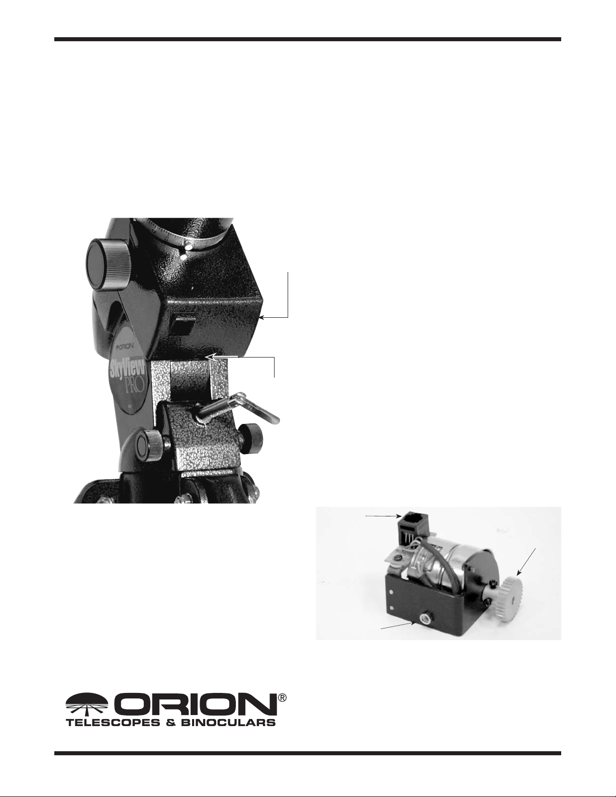
Figure 1. The R.A. motor cover.
R.A. motor
cover
Phillips-head
screw
Drive
Remove the telescope tube, counterweight, and counterweight shaft from the mount before attaching the motor drive.
1. Remove the R.A. motor cover from the mount by loosening
the Phillips head screw on the bottom of the cover (Figure
1). Slide the cover off the mount.
2. The R.A. motor assembly (Figure 2) is attached to the
mount by a socket-head cap screw that goes through the
hole in the rear of the equatorial mount, just above the rear
latitude adjustment L-bolt (Figure 3). Attach the 4mm screw
to the end of a 4mm hex key and push it up through the
hole in the rear of the equatorial mount. Hold the R.A. drive
in your hand so that its threaded hole meets up with the
screw as it comes out the other end of the hole. Thread the
screw into the threaded hole of the R.A. motor assembly
until secure, but do not overtighten. This attachment process is tricky, and it may take you several tries before you
get it right.
3. Remove the R.A. slow-motion control knob from the R.A.
worm gear shaft if it is on the side of the mount that the
Modular
jack
Parts List
1 R.A. motor assembly
1 Manual clutch assembly (brass gears)
1 Hand controller
1 Battery pack
1 4mm socket-head cap screw
2 Velcro strips (1“hook” strip, 1 “loop” strip)
Providing Exceptional Consumer Optical Products Since 1975
Brass gear
Threaded hole
Figure 2. The R.A. motor assembly.
Customer Support (800) 676-1343
E-mail: support@telescope.com
Corporate Offices (831) 763-7000
89 Hangar Way, Watsonville, CA 95076
IN 196 Rev. B 03/09
Page 2
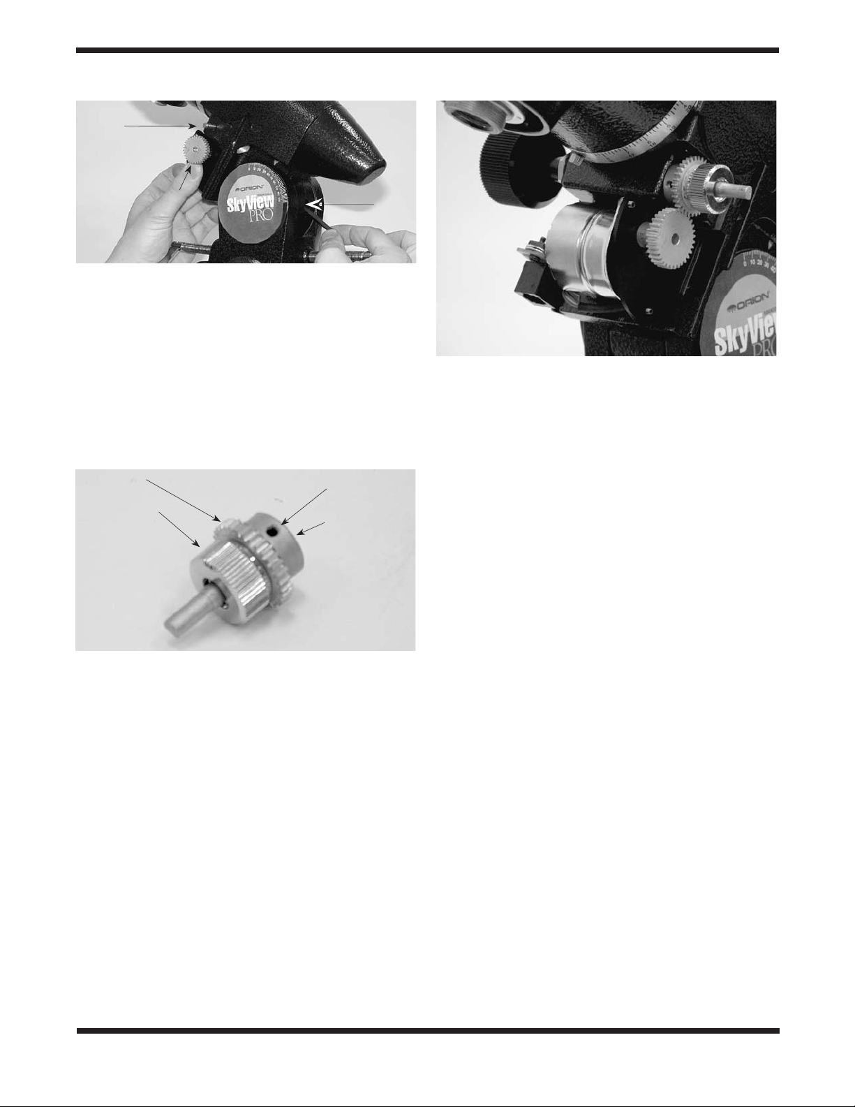
R.A. worm gear
shaft
Brass gear of R.A.
motor assembly
Figure 3. The motor is attached to the front of the mount by a
socket head cap screw pushed up through the hole in the rear of the
mount.
motor assembly’s brass gear is on, and attach it to the
opposite end of the worm gear shaft.
4. Slide the open end of the manual clutch assembly (Figure
4) onto the wormgear shaft. Rotate the manual clutch
assembly so that the setscrew will press against the flat on
the R.A. worm gear shaft. Secure the manual clutch
assembly by tightening the setscrew with a 2mm Allen
wrench.
Brass gear
Thumbwheel
Setscrew
Open end
Hole
Figure 5. The assembled R.A. motor drive.
Using the Velcro
Two strips of velcro (one strip of “hooks” and one strip of
“loops”) have been provided so you can create a place to keep
the hand controller out of the way when not in use. Place the
“hook” strip of velcro on the back of the hand controller and
the“ loops” strip on a tripod leg or on the mount where it will be
in a conveniently reached spot. Simply hang the hand controller by the velcro when it is not in use. Make certain when you
attach the velcro that the hand controller will not interfere with
the motion of the mount.
Operating the Single-Axis
Figure 4. The manual clutch assembly.
5. Make certain that the teeth of the motor assembly gear
mesh with the teeth of the manual clutch assembly gear.
Also, make certain the gears are not too tightly pressed
together. You can adjust the way the gears mesh by tightening or loosening the socket-head cap screw that is used
to attach the R.A. motor assembly to the mount. If the
gears are not meshed correctly or are too tightly pressed
together, then the drive will not track properly, or at all.
When finished, the assembled R.A. drive should resemble
Figure 5. You can now replace the R.A. motor cover and secure
it with the Phillips head screw.
Please note that if you wish to use the slow-motion control knob to move the telescope in R.A. with the R.A. motor
drive attached, you must first loosen the thumbwheel on
the manual clutch assembly. Failure to do so may result
in damage to the motor.
Drives
For the motor drive system to track properly, the equatorial
mount must be polar aligned. This involves aligning the R.A.
axis of the mount so it is parallel to the Earth’s axis of rotation
(polar axis). Consult the manual that came with your SkyView
Pro equatorial mount for details on how to polar align it.
The telescope must also be precisely balanced for the motor
drive system to properly track the night sky. Consult the manual that came with your mount for details on balancing your
telescope on the R.A. and Dec axes.
Insert four D-cell batteries into the battery pack. Orient the
batteries as indicated on the white plastic battery holder.
Connect the end of the battery pack’s power cord to the DC
power input on the hand controller.
A cord is permanently connected to the hand controller; connect the modular plug on the end of the cord to the modular
jack on the R.A. motor assembly through the hole in the bottom of the R.A. motor assembly cover.
When observing in the Northern Hemisphere, the N/S switch
on the hand controller should be set in the “N” position. For the
Southern Hemisphere, it should be in the “S” position.
Make sure the thumbwheel on the manual clutch assembly is
engaged (i.e. tightened against the brass gear), and turn the
2
Page 3

Figure 6. The hand controller.
power switch on the hand controller (Figure 6) to the “ON”
position. The LED in the center of the hand controller should
be shining green. If properly polar aligned and balanced, the
mount will now be tracking the motion of the night sky, and the
telescope should hold any astronomical object steady in its
eyepiece over time.
To move your telescope to a new object, loosen both the R.A.
and Dec. lock levers and move the telescope until it is pointed
in the general direction of the object you wish to view. Retighten
the R.A. and Dec. lock levers. Loosen the thumbwheel on the
manual clutch assembly and use the R.A. and Dec. slowmotion control knobs to center the object in the eyepiece’s
field of view. Retighten the thumbwheel, and the motor drive
system will keep the object centered over time. Remember,
never use the slow-motion control knobs when the manual
clutch is engaged or you could permanently damage the
motor.
There are four buttons on the hand controller. If no buttons are
pressed, the motor will turn the R.A. axis of the mount at sidereal rate. If the bottom right button is pressed, the drive will
turn at 2x sidereal rate, which will cause objects viewed in the
telescope’s eyepiece to move slowly eastward. If the bottom
left button is pressed, the drive will stop turning, which will
cause objects in the eyepiece to move slowly westward. The
bottom two buttons are most useful for guiding purposes during long-exposure astrophotography.
Similarly, the top right button on the hand controller moves
objects in the telescope’s eyepiece quickly eastward at 8x the
sidereal rate, while the top left button moves objects quickly
westward at 8x the sidereal rate. The top two buttons are most
useful for centering an object in R.A. within the field of view of
an eyepiece.
Note that whenever any of the four buttons on the hand controller are pressed, the LED in the center of the controller will
shine red; when the button is released, the LED will be green.
Also, when the LED starts to blink at a constant rate, its time
to change the batteries in the battery pack.
Specifications
Power requirements: 6V DC
Battery type: Four D-cells
Operation: Northern or Southern hemisphere
Guiding rates: Sidereal ±100% sidereal
Centering rates: ±8x sidereal
Manual clutch: External
One-Year Limited Warranty
This Orion TrueTrack motor drive system is warranted against defects in materials or workmanship for a period of one year from the
date of purchase. This warranty is for the benefit of the original retail purchaser only. During this warranty period Orion Telescopes
& Binoculars will repair or replace, at Orion’s option, any warranted instrument that proves to be defective, provided it is returned
postage paid to: Orion Warranty Repair, 89 Hangar Way, Watsonville, CA 95076. If the product is not registered, proof of purchase
(such as a copy of the original invoice) is required.
This warranty does not apply if, in Orion’s judgment, the instrument has been abused, mishandled, or modified, nor does it apply to
normal wear and tear. This warranty gives you specific legal rights, and you may also have other rights, which vary from state to
state. For further warranty service information, contact: Customer Service Department, Orion Telescopes & Binoculars, 89 Hangar
Way, Watsonville, CA 95076; (800) 676-1343.
Orion Telescopes & Binoculars
89 Hangar Way, Watsonville, CA 95076
Customer Support Help Line (800) 676-1343 • Day or Evening
3
 Loading...